EP2333309A2 - Energieerzeugungsanlage mit einer Luftturbine - Google Patents
Energieerzeugungsanlage mit einer Luftturbine Download PDFInfo
- Publication number
- EP2333309A2 EP2333309A2 EP10015332A EP10015332A EP2333309A2 EP 2333309 A2 EP2333309 A2 EP 2333309A2 EP 10015332 A EP10015332 A EP 10015332A EP 10015332 A EP10015332 A EP 10015332A EP 2333309 A2 EP2333309 A2 EP 2333309A2
- Authority
- EP
- European Patent Office
- Prior art keywords
- plant according
- diffuser
- diffuser section
- section
- impact body
- Prior art date
- Legal status (The legal status is an assumption and is not a legal conclusion. Google has not performed a legal analysis and makes no representation as to the accuracy of the status listed.)
- Granted
Links
- 238000010248 power generation Methods 0.000 claims abstract description 9
- 239000011358 absorbing material Substances 0.000 claims description 10
- 230000000694 effects Effects 0.000 claims description 5
- 230000009969 flowable effect Effects 0.000 claims description 4
- 239000006096 absorbing agent Substances 0.000 abstract 1
- 238000010521 absorption reaction Methods 0.000 description 4
- 230000003584 silencer Effects 0.000 description 3
- XLYOFNOQVPJJNP-UHFFFAOYSA-N water Substances O XLYOFNOQVPJJNP-UHFFFAOYSA-N 0.000 description 3
- 230000004941 influx Effects 0.000 description 2
- 239000000463 material Substances 0.000 description 2
- 230000006978 adaptation Effects 0.000 description 1
- 230000004323 axial length Effects 0.000 description 1
- 238000010276 construction Methods 0.000 description 1
- 238000013016 damping Methods 0.000 description 1
- 230000007423 decrease Effects 0.000 description 1
- 230000003247 decreasing effect Effects 0.000 description 1
- 230000005284 excitation Effects 0.000 description 1
- 238000003306 harvesting Methods 0.000 description 1
- 238000009413 insulation Methods 0.000 description 1
- 230000007774 longterm Effects 0.000 description 1
- 238000012423 maintenance Methods 0.000 description 1
- 238000005192 partition Methods 0.000 description 1
- 239000011148 porous material Substances 0.000 description 1
- 238000011144 upstream manufacturing Methods 0.000 description 1
Images




Classifications
-
- F—MECHANICAL ENGINEERING; LIGHTING; HEATING; WEAPONS; BLASTING
- F03—MACHINES OR ENGINES FOR LIQUIDS; WIND, SPRING, OR WEIGHT MOTORS; PRODUCING MECHANICAL POWER OR A REACTIVE PROPULSIVE THRUST, NOT OTHERWISE PROVIDED FOR
- F03B—MACHINES OR ENGINES FOR LIQUIDS
- F03B13/00—Adaptations of machines or engines for special use; Combinations of machines or engines with driving or driven apparatus; Power stations or aggregates
- F03B13/12—Adaptations of machines or engines for special use; Combinations of machines or engines with driving or driven apparatus; Power stations or aggregates characterised by using wave or tide energy
- F03B13/14—Adaptations of machines or engines for special use; Combinations of machines or engines with driving or driven apparatus; Power stations or aggregates characterised by using wave or tide energy using wave energy
- F03B13/141—Adaptations of machines or engines for special use; Combinations of machines or engines with driving or driven apparatus; Power stations or aggregates characterised by using wave or tide energy using wave energy with a static energy collector
- F03B13/142—Adaptations of machines or engines for special use; Combinations of machines or engines with driving or driven apparatus; Power stations or aggregates characterised by using wave or tide energy using wave energy with a static energy collector which creates an oscillating water column
-
- F—MECHANICAL ENGINEERING; LIGHTING; HEATING; WEAPONS; BLASTING
- F03—MACHINES OR ENGINES FOR LIQUIDS; WIND, SPRING, OR WEIGHT MOTORS; PRODUCING MECHANICAL POWER OR A REACTIVE PROPULSIVE THRUST, NOT OTHERWISE PROVIDED FOR
- F03B—MACHINES OR ENGINES FOR LIQUIDS
- F03B11/00—Parts or details not provided for in, or of interest apart from, the preceding groups, e.g. wear-protection couplings, between turbine and generator
- F03B11/02—Casings
-
- F—MECHANICAL ENGINEERING; LIGHTING; HEATING; WEAPONS; BLASTING
- F05—INDEXING SCHEMES RELATING TO ENGINES OR PUMPS IN VARIOUS SUBCLASSES OF CLASSES F01-F04
- F05B—INDEXING SCHEME RELATING TO WIND, SPRING, WEIGHT, INERTIA OR LIKE MOTORS, TO MACHINES OR ENGINES FOR LIQUIDS COVERED BY SUBCLASSES F03B, F03D AND F03G
- F05B2210/00—Working fluid
- F05B2210/40—Flow geometry or direction
- F05B2210/404—Flow geometry or direction bidirectional, i.e. in opposite, alternating directions
-
- F—MECHANICAL ENGINEERING; LIGHTING; HEATING; WEAPONS; BLASTING
- F05—INDEXING SCHEMES RELATING TO ENGINES OR PUMPS IN VARIOUS SUBCLASSES OF CLASSES F01-F04
- F05B—INDEXING SCHEME RELATING TO WIND, SPRING, WEIGHT, INERTIA OR LIKE MOTORS, TO MACHINES OR ENGINES FOR LIQUIDS COVERED BY SUBCLASSES F03B, F03D AND F03G
- F05B2240/00—Components
- F05B2240/10—Stators
- F05B2240/13—Stators to collect or cause flow towards or away from turbines
- F05B2240/133—Stators to collect or cause flow towards or away from turbines with a convergent-divergent guiding structure, e.g. a Venturi conduit
-
- F—MECHANICAL ENGINEERING; LIGHTING; HEATING; WEAPONS; BLASTING
- F05—INDEXING SCHEMES RELATING TO ENGINES OR PUMPS IN VARIOUS SUBCLASSES OF CLASSES F01-F04
- F05B—INDEXING SCHEME RELATING TO WIND, SPRING, WEIGHT, INERTIA OR LIKE MOTORS, TO MACHINES OR ENGINES FOR LIQUIDS COVERED BY SUBCLASSES F03B, F03D AND F03G
- F05B2260/00—Function
- F05B2260/96—Preventing, counteracting or reducing vibration or noise
-
- Y—GENERAL TAGGING OF NEW TECHNOLOGICAL DEVELOPMENTS; GENERAL TAGGING OF CROSS-SECTIONAL TECHNOLOGIES SPANNING OVER SEVERAL SECTIONS OF THE IPC; TECHNICAL SUBJECTS COVERED BY FORMER USPC CROSS-REFERENCE ART COLLECTIONS [XRACs] AND DIGESTS
- Y02—TECHNOLOGIES OR APPLICATIONS FOR MITIGATION OR ADAPTATION AGAINST CLIMATE CHANGE
- Y02E—REDUCTION OF GREENHOUSE GAS [GHG] EMISSIONS, RELATED TO ENERGY GENERATION, TRANSMISSION OR DISTRIBUTION
- Y02E10/00—Energy generation through renewable energy sources
- Y02E10/20—Hydro energy
-
- Y—GENERAL TAGGING OF NEW TECHNOLOGICAL DEVELOPMENTS; GENERAL TAGGING OF CROSS-SECTIONAL TECHNOLOGIES SPANNING OVER SEVERAL SECTIONS OF THE IPC; TECHNICAL SUBJECTS COVERED BY FORMER USPC CROSS-REFERENCE ART COLLECTIONS [XRACs] AND DIGESTS
- Y02—TECHNOLOGIES OR APPLICATIONS FOR MITIGATION OR ADAPTATION AGAINST CLIMATE CHANGE
- Y02E—REDUCTION OF GREENHOUSE GAS [GHG] EMISSIONS, RELATED TO ENERGY GENERATION, TRANSMISSION OR DISTRIBUTION
- Y02E10/00—Energy generation through renewable energy sources
- Y02E10/30—Energy from the sea, e.g. using wave energy or salinity gradient
Definitions
- the invention relates to a power generation plant with an air turbine, in particular a wave power plant with a bidirectionally flowable in the same direction rotating turbine, such as a Wells turbine.
- Wave power plants that operate on the OWC principle are known - this is exemplified on the US 5,191,225 directed.
- waves that rise with the wave cycle and lower the water level in the chamber As a result, pressure fluctuations arise in the overlying air column which generate an oscillating air flow in a flow channel leading to the outside environment.
- a bidirectionally anströmbare air turbine is arranged to generate energy.
- a possible embodiment of a bilaterally inflatable air turbine, which retains its sense of rotation independently of the direction of flow, is a Wells turbine US 4,313,711 called.
- Wells turbines have a variety of turbine blades, typically with teardrop-shaped, symmetrical profiles whose chords are in the plane of rotation of the turbine. In this case, usually rigidly arranged turbine blades are used, but also embodiments with a movable articulation of the turbine blades on a hub component are known.
- a problem of the aforementioned air turbines is their high noise emission during operation, which leads to a high
- strong turbine noise caused by a stall at the turbine blades at high flow coefficients.
- the oscillating flow in the flow channel of a wave power plant is characterized by high velocity fluctuation due to irregularities of wave excitation.
- Further sources of noise represent the multiple deflections of the driving air flow in the area of the air turbine, which are caused by additional internals and support struts, such as for an electric generator, which is assigned to the air turbine, or of shut-off valves and the like.
- wave power plants usually has to comply with noise emission limits. This applies in particular to the operation of such power generation plants in the vicinity of inhabited areas. Accordingly, wave energy harvesting devices can only be integrated into piers and breakwaters of docks if the operating noise can be reduced.
- silencers especially for Wells turbines, have been used, which have a constant cross-section and the wall surfaces are lined for sound absorption with a sound absorption material.
- Most configurations are selected for the interior of the flow channel in the region of the muffler, a core tube is provided in coaxial arrangement with the outer tube. This is located in Flow shadow of the hub of the turbine or the centrally also arranged electrical generator. Accordingly, through the core tube is given a further wall surface, which can also be covered with sound absorption material.
- the invention has for its object to make a power generation plant with a bi-directionally flowable, co-rotating air turbine in a flow channel so that the noise emission of the system is reduced during operation.
- the air turbine should have a high efficiency, which is not significantly reduced by the soundproofing measures.
- the solution should be structurally simple, in particular, an air turbine enclosing engine house for noise insulation should not be necessary.
- the inventors have recognized that an effective soundproofing and high efficiency air turbine is effected by a configuration of the mouth region of the flow channel in which the air turbine is located, for which a diffuser is combined with a sound reflecting baffle.
- a flared portion in the mouth region toward the outside environment hereinafter referred to as a diffuser portion, is known to regenerate kinetic energy by decreasing the flow velocity in the flow channel and increasing the pressure.
- the air turbine upstream for outflow to the outside environment creates a strong swirl in the wake of the flow.
- the opening angle are adapted to the swirl in the flow and selected to shorten the overall length of the diffuser and for efficient flow slowdown before the baffle plate as large as possible, the upper limit for the opening angle is set by insectsabttesen on the inner wall of the outer shell of the diffuser section.
- the outflow in the diffuser for which the maximum flow velocity, with a high swirl component afflicted, which allows to select an unusually large opening angle of the outer tube of an axial diffuser, which is preferably greater than 8 °, more preferably greater than 10 °.
- the upper limit is an opening angle of less than or equal to 14 ° of advantage.
- the large swirl and a radially outwardly directed flow component to the air turbine to the fact that even for a short diffuser according to the invention subsequent impact body without a significant loss of power can be arranged in front of the outlet opening of the diffuser that its projection at least the entire free cross-section covered by the diffuser.
- the damping is improved by covering the inner wall of the diffuser section and / or the impact body with a sound-absorbing material.
- the slowed-down and radially outward-directed air flow can escape to the outside environment between the wall of the diffuser section and the impact body without significant pressure losses, wherein preferably the flow passage area available for this purpose essentially corresponds to the maximum free cross section at the outlet of the diffuser section.
- the outflow thus takes place substantially unhindered.
- a nozzle-shaped inlet member may join the flow passage area, reducing turbulence in the flow.
- the impact body may be applied as a substantially annular element which surrounds a likewise annularly shaped mouth region of the flow channel for a radially flowed turbine.
- FIG. 1 schematically schematically a flow channel 1 is sketched with a mouth region 2, which opens to the outside environment 3 out.
- a mouth region 2 which opens to the outside environment 3 out.
- the external environment 3 it is simplifiedly assumed that there is such a sufficiently large free volume that the inflow and outflow from the flow channel 1 does not lead to any significant pressure fluctuations.
- a bidirectionally flowable, in the same direction circulating air turbine 5 is arranged in the flow channel 1, which is designed here as a Wells turbine and has a turbine stage. Further turbine stages or a distributor are conceivable, but not shown.
- the turbine stage drives a centrally arranged in the flow channel 1 electric generator 17.
- the air turbine 5 is flowed axially and has a direction of rotation parallel to the longitudinal axis 7 of the flow channel 1.
- a diffuser section 4 is provided in the mouth region 2 of the flow channel 1. This preferably has an opening angle of greater than 8 ° for the outer diffuser part 20.
- the outer wall angle 10 relative to the longitudinal axis 7, which defines the half the opening angle of the inner wall of the outer diffuser part 20, outlined.
- a core tube hereinafter referred to as the central element 11, is provided, which tapers in the direction of the mouth for the embodiment shown and thus increases the flow-decelerating effect of the diffuser section 4.
- a baffle 6 is arranged, which is designed symmetrically to the longitudinal axis 7 and the radial extent is chosen so that a projection of its outer contour at least completely covers the maximum free cross section 12 of the diffuser section 4.
- the baffle 6 is, with respect to the outflow, arranged downstream of the diffuser section 4 and is thus located in a region of a substantially slowed down in the axial and in the circumferential direction outflow velocity.
- the impact body 6 is spaced from the wall in the mouth region 2 of the diffuser section 4 in such a way that the resulting flow passage area 13, which in the present case is substantially annular, corresponds at least to the maximum free cross section 12 associated with the diffuser section 4.
- the essential sound-reducing effect of the impact body 6 is to cover the cross-section of the flow channel 1 in the direction of the mouth and reflect sound into the flow channel 1 back or absorb. Furthermore, the inwardly facing wall of the diffuser section 4, the central element 11 and the wall of the impact body 6 facing the flow channel 1 is covered at least in some areas with a sound-absorbing material 8.1, 8.2, 8.3. In the present case, a highly porous material with good sound absorption properties is used in those areas for which a sufficient flow slowdown has already occurred. By this measure, the stability of the sound-absorbing material 8.1, 8.2, 8.3 increases.
- another sound-absorbing material 8.4 can be used, which is designed for higher loads.
- Such highly stressed areas are also present on the wall parts of the diffuser section 4, where intermediate detachments can not be completely ruled out.
- at least sections of the sound-absorbing material can be dispensed with entirely.
- FIG. 1 shown embodiment variant of the one-piece baffle body 6 via support webs 9.1, 9.2, 9.3, 9.4, 9.5, 9.6, 9.7 connected to the diffuser section 4.
- FIG. 2 a further embodiment of the invention with a multi-part baffle 6 is shown.
- the projection of the entirety of the outer contours of the impact body components 6.1, 6.2, 6.3 is applied to the outlet of the diffuser section 4 so that the maximum free cross section 12 of the diffuser section 4 is completely covered in order to bring about the most efficient possible Schall Wegrefletation in the flow channel 1.
- the impact body components 6.1, 6.2, 6.3 connected to one another via the support webs 9.8 - 9.14 produce a central opening 18 in addition to the radially outer flow passage area 13.
- the essential factor is an outflow due to the high swirl to the air turbine 5 Air volume over the flow passage area 13 to the outside environment 3 out.
- the central opening 18 of the influx can be improved.
- This central opening 18 is covered by the baffle component 6.2 for sound reduction.
- Another embodiment not shown in detail, provides a partially permeable impact body.
- FIG. 2 sketched a link element 19 which is arranged between the outer diffuser part 20 and the central element 11.
- This serves the purpose of further noise reduction, especially for large-scale diffusers, for which the distance between the outer diffuser part 20 and the central element 11 would otherwise be too large for the frequencies to be damped.
- the link element 19 of the flow guide and can be arranged and designed accordingly, and also several link elements 19 are conceivable.
- FIG. 3 Another design alternative is in FIG. 3 shown schematically simplified.
- the central element 11 has been extended axially for supporting the impact body 6 and has a constant cross-section.
- Particularly preferred is a one-piece design of the central element 11 and the impact body. 6
- FIG. 4 shows a redesign of the in FIG. 3 sketched embodiment.
- a widening in the mouth direction central element 11 is provided.
- the central element 11, a positive inner wall angle 21 are assigned.
- embodiments are particularly preferred for which the inner wall angle 21 of the central element 11 is greater than the outer wall angle 10 of the outer diffuser part 20.
- FIG. 4 sketched an embodiment for which a nozzle-shaped inlet element 14 connects to the diffuser section 4 in the direction of the mouth.
- the nozzle-shaped inlet element 14 preferably has at least one intermediate wall 15, so that turbulences when flowing through the nozzle shape are reduced.
- the baffle 6 passes into the nozzle-shaped inlet element 14 and forms one of its wall sections.
- FIG. 4 sketched nozzle-shaped inlet member 14 acts in the outflow direction as a radial diffuser.
- the diffuser section 4 of the mouth region 2 comprises a combination of an axial diffuser 4.1 and a downstream for the outflow radial diffuser 4.2.
- the direction of the opening is the radial radial predetermined by the radial diffuser 4.2 and the impact body 6 following the diffuser section 4 in the direction of the mouth is designed as a substantially annular element which absorbs and reflects back the airborne sound emerging from the radial diffuser 4.2.
- FIG. 5 shows a further embodiment with a diffuser section 4 in the form of an axial-radial diffuser, which is associated with an annular baffle 6.
- the embodiment has a central element 11, the maximum radial extent decreases continuously perpendicular to the axial direction in a first axial portion 23 to a radial constriction 25 and continuously increasing in a second axial portion 24 of the radial constriction 25, wherein the second axial portion 24 of the first axial section 23 follows in the direction of discharge and extends to the outside environment 3.
- examples of radii r1, r2, r3, r4 representing the cross-sectional dimensions are selected, where r2 is smaller than r1, r3 and r4.
- the radial constriction 25 serves to stabilize a stationary flow vortex, which adaptively adapts the effective cross section of the central element 11.
- FIG. 7 shows an alternative embodiment of the invention in longitudinal section for a radially flowed through the air turbine 5.
- the mouth direction radially relative to the axis of rotation 16 of the air turbine 5. Due to the radial outflow direction increases in the mouth direction of the free Cross section continuously closed.
- the diffuser effect is additionally improved by an angular position of the walls in the mouth region 2 relative to the radial in the diffuser section 4.
- the impact body 6 covers the maximum free cross section 12 in the projection. Accordingly, the baffle body 6 is formed substantially annular. Again, an embodiment is conceivable for which the impact body 6 is applied segmented. Thus, a subdivision in the circumferential direction, possibly with overlapping segments in question. Further embodiments of the invention will become apparent from the following claims.
Landscapes
- Engineering & Computer Science (AREA)
- Chemical & Material Sciences (AREA)
- Combustion & Propulsion (AREA)
- Mechanical Engineering (AREA)
- General Engineering & Computer Science (AREA)
- Other Liquid Machine Or Engine Such As Wave Power Use (AREA)
- Structures Of Non-Positive Displacement Pumps (AREA)
Abstract
Description
- Die Erfindung betrifft eine Energieerzeugungsanlage mit einer Luftturbine, insbesondere ein Wellenkraftwerk mit einer bidirektional anströmbaren gleichsinnig umlaufenden Turbine, wie einer Wells-Turbine.
- Wellenkraftwerke, die nach dem OWC-Prinzip arbeiten, sind bekannt - hierzu wird exemplarisch auf die
US 5,191,225 verwiesen. Dabei erzeugen gegen eine Wellenkammer mit einem unter dem Wasserspiegel liegenden Zustrom anbrandende Wellen einen sich mit dem Wellentakt hebenden und senkenden Wasserspiegel in der Kammer. Als Folge entstehen in der darüber befindlichen Luftsäule Druckschwankungen, die einen oszillierenden Luftstrom in einem zur Außenumgebung führenden Strömungskanal erzeugen. In diesem ist zur Energiegewinnung eine bidirektional anströmbare Luftturbine angeordnet. - Eine mögliche Ausführungsform einer beidseitig anströmbaren Luftturbine, die unabhängig von der Anströmungsrichtung ihren Drehsinn beibehält, stellt eine Wells-Turbine dar. Hierzu wird beispielhaft die
US 4,313,711 genannt. Wells-Turbinen weisen eine Vielzahl von Turbinenblättern auf, mit typischerweise tropfenförmigen, symmetrischen Profilen, deren Profilsehnen in der Rotationsebene der Turbine liegen. Dabei werden üblicherweise starr angeordnete Turbinenblätter verwendet, allerdings sind auch Ausgestaltungen mit einer beweglichen Anlenkung der Turbinenblätter an einem Nabenbauteil bekannt. - Als Alternative zu axial durchströmten Wells-Turbinen ist in der
US 4,533,292 A eine gleichsinnig umlaufende Luftturbine für eine oszillierende Anströmung offenbart, die radial durchströmt wird. Alternative Bauformen zu Wells-Turbinen stellen Impulsturbinen dar, die beispielsweise in derWO 06137696 A1 - Ein Problem der voranstehend genannten Luftturbinen ist deren hohe Geräuschemission beim Betrieb, die zum einem auf die hohe Umlaufgeschwindigkeit der Turbine zurückzuführen ist, zum anderen entstehen starke Turbinengeräusche durch einen Strömungsabriss an den Turbinenblättern bei hohen Durchflusskoeffizienten. Darüber hinaus ist die oszillierende Strömung im Strömungskanal eines Wellenkraftwerks durch starke Geschwindigkeitsfluktuation gekennzeichnet, die auf Unregelmäßigkeiten der Wellenanregung zurückzuführen sind. Weitere Geräuschquellen stellen die vielfachen Umlenkungen der antreibenden Luftströmung im Bereich der Luftturbine dar, die durch zusätzliche Einbauten sowie Tragstreben, etwa für einen elektrischen Generator, der der Luftturbine zugeordnet ist, oder von Sperrventilen und dergleichen verursacht werden.
- Beim Bau von Wellenkraftwerken sind meist Lärmemissionsgrenzwerte einzuhalten. Dies gilt insbesondere beim Betrieb solcher Energieerzeugungsanlagen in der Nähe bewohnter Gebiete. Entsprechend können Vorrichtungen zur Gewinnung von Wellenenergie nur dann in Molen und Wellenbrechern von Hafenanlagen integriert werden, wenn die Betriebsgeräusche reduziert werden können.
- Als eine mögliche Maßnahme zur Lärmbekämpfung wurde vorgeschlagen, Strömungskanäle von Wellenkraftwerken in hierfür vorgesehene Maschinenhäuser münden zu lassen. Diese müssen großbauend angelegt sein oder die Anlagenleistung muss begrenzt werden.
- Wird alternativ jeder gattungsgemäßen Luftturbine ein separater Schalldämpfer zugeordnet, so ist eine wesentliche Voraussetzung, dass durch den Schalldämpfer kein die Anlagenleistung wesentlich reduzierender Druckverlust eintritt. Entsprechend wurden bisher Schalldämpfer, insbesondere für Wells-Turbinen, verwendet, die einen gleich bleibenden Querschnitt aufweisen und deren Wandungsflächen zur Schallabsorption mit einem Schallschluckmaterial ausgekleidet sind. Meist werden Ausgestaltungen gewählt, für die im Innern des Strömungskanals im Bereich des Schalldämpfers ein Kernrohr in koaxialer Anordnung zum Außenrohr vorgesehen ist. Dieses befindet sich im Strömungsschatten der Nabe der Turbine beziehungsweise des ebenfalls zentral angeordneten elektrischen Generators. Entsprechend ist durch das Kernrohr eine weitere Wandungsfläche gegeben, die ebenfalls mit Schallschluckmaterial bedeckt werden kann.
- Die bisher bekannt gewordenen koaxial angeordneten Schalldämpfer für Wells-Turbinen sind bisher nicht hinreichend effizient. Darüber hinaus besteht aufgrund der hohen Durchtrittsgeschwindigkeiten der Luftströmung durch derartige Schalldämpfer und durch Ablösungen an den Turbinenschaufeln verursachte Turbulenzen das Problem, dass das notwendigerweise porös und damit weich ausgebildete Schallschluckmaterial auf Dauer den Belastungen nicht standhält und der Schalldämpfer daher einer regelmäßigen Wartung unterliegt.
- Der Erfindung liegt die Aufgabe zugrunde, eine Energieerzeugungsanlage mit einer bidirektional anströmbaren, gleichsinnig umlaufenden Luftturbine in einem Strömungskanal so zu gestalten, dass die Lärmemission der Anlage beim Betrieb reduziert ist. Dabei soll die Luftturbine einen hohen Wirkungsgrad aufweisen, der nicht wesentlich durch die Schallschutzmaßnahmen reduziert ist. Ferner soll die Lösung konstruktiv einfach sein, wobei insbesondere ein die Luftturbine umschließendes Maschinenhaus zur Geräuschkapselung nicht notwendig sein sollte.
- Die der Erfindung zugrunde liegende Aufgabe wird durch Merkmale des unabhängigen Anspruchs gelöst. Vorteilhafte Ausgestaltungen ergeben sich aus den Unteransprüchen.
- Die Erfinder haben erkannt, dass ein effektiver Schallschutz und eine Luftturbine mit hohem Wirkungsgrad durch eine Ausgestaltung des Mündungsbereichs des Strömungskanals, in dem sich die Luftturbine befindet, bewirkt wird, für die ein Diffusor mit einem schallreflektierenden Prallkörper kombiniert wird.
- Ein sich aufweitender Abschnitt im Mündungsbereich zur Außenumgebung hin, der nachfolgend als Diffusorabschnitt bezeichnet wird, dient bekanntermaßen der Rückgewinnung kinetischer Energie, indem die Strömungsgeschwindigkeit im Strömungskanal ab- und der Druck zunimmt. Vorliegend erzeugt die für eine Ausströmung zur Außenumgebung hin stromaufwärts gelegene Luftturbine einen starken Drall im Nachlauf der Strömung. Dies erlaubt die Verwendung großer Öffnungswinkel für die Innenwandung der Außenschale des Diffusorabschnitts. Dabei werden die Öffnungswinkel an den Drall in der Strömung angepasst und zur Verkürzung der Baulänge des Diffusors und zur effizienten Strömungsverlangsamung vor der Prallplatte möglichst groß gewählt, wobei die Obergrenze für den Öffnungswinkel durch Zwischenablösungen an der Innenwandung der Außenschale des Diffusorabschnitts festgelegt wird. Für die schnell und gleichsinnig umlaufenden Luftturbinen der gattungsgemäßen Wellenkraftwerke ist die Ausströmung im Diffusor, für die die maximale Strömungsgeschwindigkeit vorliegt, mit einer hohen Drallkomponente behaftet, die es erlaubt, einen unüblich großen Öffnungswinkel des Außenrohrs eines axialen Diffusors zu wählen, der bevorzugt größer als 8°, besonders bevorzugt größer als 10° ist. Des Weiteren ist als Obergrenze ein Öffnungswinkel kleiner oder gleich 14° von Vorteil.
- Des Weiteren führt der große Drall und eine nach radial außen gerichtete Strömungskomponente nach der Luftturbine dazu, dass auch für einen Kurzdiffusor der erfindungsgemäß nachfolgende Prallkörper ohne einen wesentlichen Leistungsverlust so vor der der Austrittsöffnung des Diffusors angeordnet werden kann, dass dessen Projektion wenigstens den gesamten freien Querschnitt des Diffusors überdeckt. Als Folge wird der in Mündungsrichtung transportierte Schall zu wesentlichen Teilen in den Strömungskanal zurück reflektiert. Zusätzlich wird die Dämpfung durch eine Bedeckung der Innenwandung des Diffusorabschnitts und/oder des Prallkörpers mit einem schallabsorbierenden Material verbessert.
- Die verlangsamte und nach radial außen geführte Luftströmung kann zur Außenumgebung hin zwischen der Wandung des Diffusorabschnitts und dem Prallkörper ohne wesentliche Druckverluste entweichen, wobei bevorzugt die hierfür zur Verfügung stehende Strömungsdurchgangsfläche im Wesentlichen dem maximalen freien Querschnitt am Ausgang des Diffusorabschnitts entspricht. Die Ausströmung erfolgt demnach im Wesentlichen ungehindert. Um eine Einströmung in die Gegenrichtung zum Strömungskanal zu verbessern, kann sich ein düsenförmiges Einlasselement an die Strömungsdurchgangsfläche anschließen, das Turbulenzen im Zustrom verringert.
- Im einfachsten Fall besteht der Prallkörper für eine axial durchströmte Luftturbine und einem kreisförmigen Querschnitt des Strömungskanals aus einer scheibenförmigen Prallplatte, die axial beabstandet zum Diffusorabschnitt zentral zur Längsachse des Strömungskanals angeordnet ist. Für Luftturbinen mit radialer Durchströmung kann der Prallkörper als im Wesentlichen ringförmiges Element angelegt sein, das einen ebenfalls ringförmig angelegten Mündungsbereich des Strömungskanals für eine radial durchströmte Turbine umgibt.
- Vorteilhafte Ausgestaltungen der Erfindung werden nachfolgend anhand von bevorzugten Ausgestaltungsbeispielen und in Verbindung mit Figurendarstellungen genauer erläutert. In diesen ist im Einzelnen Folgendes dargestellt:
- Figur 1
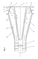
- zeigt den Mündungsbereich eines Strömungskanals für eine erfindungsgemäße Energieerzeugungsanlage im Längsschnitt.
- Figur 2
- zeigt eine weitere erfindungsgemäße Ausgestaltung im Längsschnitt mit einem mehrteiligen,Prallkörper.
- Figur 3
- zeigt eine weitere erfindungsgemäße Ausgestaltungsvariante mit einem Prallkörper, der einstückig mit einem Zentralelement im Diffusorabschnitt verbunden ist, im Längsschnitt.
- Figur 4
- zeigt eine weitere erfindungsgemäße Ausgestaltungsvariante im Längsschnitt mit einem sich aufweitenden Zentralelement und einem zusätzlichen, düsenförmigen Einlasselement.
- Figur 5
- zeigt eine weitere erfindungsgemäße Ausgestaltungsalternative im Längsschnitt mit einer Kombination eines axialen und radialen Diffusors (Axial-Radial-Diffusor) und einem radial anschließenden Prallkörper.
- Figur 6
- zeigt eine weitere erfindungsgemäße Ausgestaltungsalternative im Längsschnitt mit einem Axial-Radial-Diffusor, dessen Zentralelement eine radiale Einschnürung aufweist.
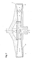
- Figur 7
- zeigt eine erfindungsgemäße Gestaltung für eine radial durchströmte Luftturbine im Längsschnitt.
- In
Figur 1 wird schematisch vereinfacht ein Strömungskanal 1 mit einem Mündungsbereich 2 skizziert, der sich zur Außenumgebung 3 hin öffnet. Für die Außenumgebung 3 wird vereinfacht angenommen, dass dort ein so hinreichend großes Freivolumen vorliegt, dass die Ein- und Ausströmung aus dem Strömungskanal 1 zu keinen wesentlichen Druckschwankungen führt. - Des Weiteren ist im Strömungskanal 1 eine bidirektional anströmbare, gleichsinnig umlaufende Luftturbine 5 angeordnet, die vorliegend als Wells-Turbine gestaltet ist und eine Turbinenstufe aufweist. Weitere Turbinenstufen oder ein Leitapparat sind denkbar, jedoch nicht dargestellt. Die Turbinenstufe treibt einen zentral im Strömungskanal 1 angeordneten elektrischen Generator 17 an. Vorliegend wird die Luftturbine 5 axial angeströmt und weist eine parallel zur Längsachse 7 des Strömungskanals 1 verlaufende Drehachse auf.
- Erfindungsgemäß ist im Mündungsbereich 2 des Strömungskanals 1 ein Diffusorabschnitt 4 vorgesehen. Dieser weist für den äußeren Diffusorteil 20 bevorzugt einen Öffnungswinkel von größer als 8° auf. Dabei gibt die Längsachse 7 und die Lage des Mündungsbereichs 2 die Mündungsrichtung vor, die für die vorliegende Gestaltung axial orientiert ist. In
Figur 1 ist der äußere Wandungswinkel 10 relativ zur Längsachse 7, der den halben Öffnungswinkel der Innenwandung des äußeren Diffusorteils 20 festlegt, skizziert. Zusätzlich ist symmetrisch zur Längsachse 7 im Inneren des Diffusorabschnitts 4 ein Kernrohr, nachfolgend als Zentralelement 11 bezeichnet, vorgesehen, das sich für das gezeigte Ausführungsbeispiel in Mündungsrichtung verjüngt und so den strömungsverlangsamenden Effekt des Diffusorabschnitts 4 erhöht. - In Mündungsrichtung und damit vorliegend axial zum Diffusorabschnitt 4 beabstandet ist ein Prallkörper 6 angeordnet, der symmetrisch zur Längsachse 7 gestaltet ist und dessen radiale Erstreckung so gewählt ist, dass eine Projektion seiner Außenkontur den maximalen freien Querschnitt 12 des Diffusorabschnitts 4 wenigstens vollständig überdeckt. Der Prallkörper 6 ist, bezogen auf die Ausströmung, nachfolgend zum Diffusorabschnitt 4 angeordnet und befindet sich damit in einem Bereich einer in Axial- und in Umfangsrichtung wesentlich verlangsamten Ausströmungsgeschwindigkeit.
- Des Weiteren ist aufgrund der mit einem hohen Drall in den Diffusorabschnitt 4 von der Luftturbine 5 aus eintretenden Strömung ein großer äußerer Wandungswinkel 10 für die Innenwandung des äußeren Diffusorteils 20 möglich, sodass auch bei einer begrenzten axialen Baulänge des Diffusorabschnitts 4 der nachfolgende Prallkörper 6 kein den Wirkungsgrad wesentlich reduzierendes Strömungshindernis darstellt. Besonders bevorzugt wird der Prallkörper 6 von der Wandung im Mündungsbereich 2 des Diffusorabschnitts 4 derart beabstandet, dass die resultierende Strömungsdurchgangsfläche 13, die vorliegend im Wesentlichen ringförmig angelegt ist, wenigstens dem maximalen freien Querschnitt 12 entspricht, der dem Diffusorabschnitt 4 zugeordnet ist.
- Die wesentliche schallreduzierende Wirkung des Prallkörpers 6 besteht darin, den Querschnitt des Strömungskanals 1 in Mündungsrichtung abzudecken und Schall in den Strömungskanal 1 zurück zu reflektieren oder zu absorbieren. Des Weiteren ist die nach innen weisende Wandung des Diffusorabschnitts 4, des Zentralelements 11 sowie der dem Strömungskanal 1 zugewandten Wandung des Prallkörpers 6 wenigstens in Teilbereichen mit einem schallabsorbierenden Material 8.1, 8.2, 8.3 bedeckt. Vorliegend wird hierfür ein hochporöses Material mit guten Schallschluckeigenschaften in jenen Bereichen eingesetzt, für die bereits eine hinreichende Strömungsverlangsamung eingetreten ist. Durch diese Maßnahme erhöht sich die Standfestigkeit des schallabsorbierenden Materials 8.1, 8.2, 8.3. Entsprechend kann in den Bereichen mit hohen Strömungsgeschwindigkeiten und Turbulenzen, insbesondere im luftturbinenseitigen Einlassbereich des Diffusorabschnitts 4, ein anderes schallabsorbierendes Material 8.4 verwendet werden, das für höhere Belastungen ausgelegt ist. Solche hochbelasteten Bereiche liegen auch an den Wandungsteilen des Diffusorabschnitts 4 vor, an denen Zwischenablösungen nicht gänzlich ausgeschlossen werden können. Ferner kann anstatt oder zusätzlich zur Belastungsanpassung des schallabsorbierenden Materials 8.4 wenigstens abschnittsweise gänzlich auf das Schallschluckmaterial verzichtet werden.
- Für die in
Figur 1 gezeigte Ausgestaltungsvariante ist der einteilige Prallkörper 6 über Tragstege 9.1, 9.2, 9.3, 9.4, 9.5, 9.6, 9.7 mit dem Diffusorabschnitt 4 verbunden. InFigur 2 ist eine weitere Ausführungsform der Erfindung mit einem mehrteiligen Prallkörper 6 gezeigt. Dabei wird wiederum die Projektion der Gesamtheit der Außenkonturen der Prallkörperkomponenten 6.1, 6.2, 6.3 auf den Ausgang des Diffusorabschnitts 4 so angelegt, dass der maximale freie Querschnitt 12 des Diffusorabschnitts 4 gänzlich abgedeckt ist, um eine möglichst effiziente Schallrückreflektion in den Strömungskanal 1 zu bewirken. Die untereinander über die Tragstege 9.8 - 9.14 verbundenen Prallkörperkomponenten 6.1, 6.2, 6.3 erzeugen zusätzlich zur radial äußeren Strömungsdurchgangsfläche 13 eine zentrale Öffnung 18. Für eine Ausströmung wird aufgrund des hohen Dralls nach der Luftturbine 5 das wesentliche Luftvolumen über die Strömungsdurchgangsfläche 13 zur Außenumgebung 3 geführt. Für eine Einströmung in den Strömungskanal 1 kann jedoch durch die zentrale Öffnung 18 der Zustrom verbessert werden. Diese zentrale Öffnung 18 wird durch die Prallkörperkomponente 6.2 zur Schallreduktion abgedeckt. Eine weitere im Einzelnen nicht dargestellte Ausgestaltung sieht einen teildurchlässigen Prallkörper vor. - Ferner ist in
Figur 2 ein Kulissenelement 19 skizziert, das zwischen dem äußeren Diffusorteil 20 und dem Zentralelement 11 angeordnet ist. Dies dient dem Zweck einer weiteren Schallreduktion, insbesondere für großbauende Diffusoren, für die der Abstand zwischen dem äußeren Diffusorteil 20 und dem Zentralelement 11 für die zu dämpfenden Frequenzen andernfalls zu groß werden würde. Des Weiteren dient das Kulissenelement 19 der Strömungsführung und kann entsprechend angeordnet und gestaltet sein, auch mehrere Kulissenelemente 19 sind denkbar. - Eine weitere Ausgestaltungsalternative ist in
Figur 3 schematisch vereinfacht gezeigt. Dabei wurde das Zentralelement 11 zum Tragen des Prallkörpers 6 axial verlängert und weist einen gleichbleibenden Querschnitt auf. Besonders bevorzugt wird eine einstückige Ausbildung des Zentralelements 11 und des Prallkörpers 6. -
Figur 4 zeigt eine Weitergestaltung der inFigur 3 skizzierten Ausführungsform.
Dabei wird zur Anpassung an den hohen Drall und die radialen Richtungskomponenten abstromseitig zur Luftturbine ein sich in Mündungsrichtung aufweitendes Zentralelement 11 vorgesehen. Für die dargestellte Ausführung kann dem Zentralelement 11 ein positiver innerer Wandungswinkel 21 zugeordnet werden. Dabei sind Ausgestaltungen besonders bevorzugt, für die der innere Wandungswinkel 21 des Zentralelements 11 größer ist als der äußere Wandungswinkel 10 des äußeren Diffusorteils 20. Durch die Form des Zentralelements 11 wird der Totwasserbereich ausgefüllt und es ist möglich, einen sich stark aufweitenden und kurzbauenden axialen Diffusor oder einen Axial-Radial-Diffusor zu realisieren. - Des Weiteren ist in
Figur 4 eine Ausgestaltung skizziert, für die ein düsenförmiges Einlasselement 14 an den Diffusorabschnitt 4 in Mündungsrichtung anschließt. Dabei werden insbesondere Strömungsverluste der von der Außenumgebung 3 beim Ansaugen zufließenden Strömung reduziert. Das düsenförmige Einlasselement 14 weist bevorzugt wenigstens eine Zwischenwand 15 auf, sodass Turbulenzen beim Einströmen durch die Düsenform verringert werden. Für die skizzierte Ausgestaltungsvariante geht der Prallkörper 6 in das düsenförmige Einlasselement 14 über und bildet einen seiner Wandabschnitte. - Das in
Figur 4 skizzierte düsenförmige Einlasselement 14 wirkt in Ausströmungsrichtung als radialer Diffusor. Für eine Weitergestaltung, die inFigur 5 skizziert ist, umfasst der Diffusorabschnitt 4 des Mündungsbereichs 2 eine Kombination aus einem Axialdiffusor 4.1 und einem für die Ausströmung abstromseitig anschließenden Radialdiffusor 4.2. Demnach ist die Mündungsrichtung die durch den Radialdiffusor 4.2 vorgegebene Radiale und der in Mündungsrichtung dem Diffusorabschnitt 4 nachfolgende Prallkörper 6 ist als ein im Wesentlichen ringförmiges Element angelegt, das den aus dem Radialdiffusor 4.2 austretenden Luftschall abdämpft und rückreflektiert. -
Figur 5 zeigt eine weitere Ausgestaltung mit einem Diffusorabschnitt 4 in Form eines Axial-Radialdiffusors, dem ein ringförmiger Prallkörper 6 zugeordnet ist. Dabei weist das Ausführungsbeispiel ein Zentralelement 11 auf, dessen maximale radiale Erstreckung senkrecht zur Axialrichtung in einem ersten Axialabschnitt 23 bis zu einer radiale Einschnürung 25 kontinuierlich abnimmt und in einem zweiten Axialabschnitt 24 von der radialen Einschnürung 25 ausgehend kontinuierlich zunimmt, wobei der zweite Axialabschnitt 24 dem ersten Axialabschnitt 23 in Ausblasrichtung nachfolgt und bis zur Außenumgebung 3 reicht. Zur Verdeutlichung der Kontur des Zentralelements 11 sind exemplarisch gewählte, die Querschnittsabmessungen repräsentierende Radien r1, r2, r3, r4 eingezeichnet, wobei r2 kleiner als r1, r3 und r4 ist. Die radiale Einschnürung 25 dient dazu, einen stationären Strömungswirbel zu stabilisieren, der den effektiven Querschnitt des Zentralelements 11 adaptiv anpasst. -
Figur 7 zeigt eine alternative Ausgestaltung der Erfindung im Längsschnitt für eine radial durchströmte Luftturbine 5. Entsprechend zur Ausströmungsrichtung und dem ringförmig angelegten Mündungsbereich 2 des Strömungskanals 1 ist vorliegend die Mündungsrichtung radial im Verhältnis zur Drehachse 16 der Luftturbine 5. Aufgrund der radialen Ausströmungsrichtung nimmt in Mündungsrichtung der freie Querschnitt kontinuierlich zu. Bevorzugt wird der Diffusoreffekt durch eine Winkelstellung der Wandungen im Mündungsbereich 2 relativ zur Radiale im Diffusorabschnitt 4 zusätzlich verbessert. Hierzu sind inFigur 7 die ober- und unterseitigen Wandungswinkel 10.1, 10.2 skizziert. Ferner sind im Einzelnen nicht dargestellte Ausgestaltungen denkbar, für die die Ober- und Unterseiten parallel verlaufen oder nach innen zur Radialen hin verkippt sind, d.h. es liegen negative Wandungswinkel vor. Für die letztgenannte Gestaltung soll sich weiterhin aufgrund der Aufweitung in Radialrichtung des scheibenförmig angelegten Mündungsbereichs 2 eine Diffusorwirkung ergeben, die jedoch zur Vermeidung von Zwischenablösungen der Ausströmung durch die nach innen geneigten Ober- und Unterseite reduziert wird. - Des Weiteren deckt in der vorliegenden Ausgestaltungsvariante der Prallkörper 6 den maximalen freien Querschnitt 12 in der Projektion ab. Entsprechend ist der Prallkörper 6 im Wesentlichen ringförmig ausgebildet. Dabei ist wiederum eine Ausgestaltung denkbar, für die der Prallkörper 6 segmentiert angelegt ist. So kommt eine Unterteilung in Umfangsrichtung, eventuell mit überlappenden Segmenten, in Frage. Weitere Ausgestaltungsvarianten der Erfindung ergeben sich aus den nachfolgenden Schutzansprüchen.
-
- 1
- Strömungskanal
- 2
- Mündungsbereich
- 3
- Außenumgebung
- 4
- Diffusorabschnitt
- 4.1
- Axialdiffusor
- 4.2
- Radialdiffusor
- 5
- Luftturbine
- 6
- Prallkörper
- 6.1, 6.2, 6.3
- Prallkörperteilkomponente
- 7
- Längsachse
- 8.1 - 8.4
- schallabsorbierendes Material
- 9.1, 9.2, 9.3
- 9.4, 9.5, 9.6
- 9.7, 9.8, 9.10,
- 9.11,9.12,
- 9.13,9.14
- Tragsteg
- 10, 10.1, 10.2
- äußerer Wandungswinkel
- 11
- Zentralelement
- 12
- maximaler freier Querschnitt
- 13
- Strömungsdurchgangsfläche
- 14
- düsenförmiges Einlasselement
- 15
- Zwischenwand
- 16
- Drehachse
- 17
- elektrischer Generator
- 18
- zentrale Öffnung
- 19
- Kulissenelement
- 20
- äußeres Diffusorteil
- 21
- innerer Wandungswinkel
- 22.1, 22.2
- 22.3,22.4
- Strebe
- 23
- erster Axialabschnitt
- 24
- zweiter Axialabschnitt
- 25
- radiale Einschnürung
- 26
- Strömungswirbel
- r1, r2, r3, r4
- Radien
Claims (16)
- Energieerzeugungsanlage umfassend:1.1 einen Strömungskanal (1) mit einem Mündungsbereich (2) zur Außenumgebung (3) mit einer zugeordneten Mündungsrichtung, wobei der Mündungsbereich (2) als Diffusorabschnitt (4) gestaltet ist;1.2 eine bidirektional anströmbare Luftturbine (5) mit gleichsinniger Umlaufrichtung, die im Strömungskanal (1) angeordnet ist;
dadurch gekennzeichnet, dass1.3 dem Mündungsbereich (2) ein Prallkörper (6) als Schalldämpfer zugeordnet ist, der dem Diffusorabschnitt (4) in Mündungsrichtung nachfolgt. - Energieerzeugungsanlage nach Anspruch 1, dadurch gekennzeichnet, dass die Projektion des Prallkörpers (6) auf den Mündungsbereich (2) in Mündungsrichtung den maximalen freien Querschnitt (12) des Diffusorabschnitts (4) wenigstens vollständig überdeckt.
- Energieerzeugungsanlage nach einem der Ansprüche 1 oder 2, dadurch gekennzeichnet, dass die Luftturbine (5) als Wells-Turbine gestaltet ist.
- Energieerzeugungsanlage nach einem der vorausgehenden Ansprüche,
dadurch gekennzeichnet, dass die Mündungsrichtung die Axialrichtung des Strömungskanals (1) ist. - Energieerzeugungsanlage nach Anspruch 4, dadurch gekennzeichnet, dass der Prallkörper (6) als eine symmetrisch zur Axialrichtung liegende Prallplatte ausgebildet ist.
- Energieerzeugungsanlage nach einem der vorausgehenden Ansprüche,
dadurch gekennzeichnet, dass der Diffusorabschnitt (4) einen Axialdiffusor (4.1) und einen Radialdiffusor (4.2) umfasst. - Energieerzeugungsanlage nach einem der Ansprüche 1 bis 3, dadurch gekennzeichnet, dass die Luftturbine eine radial durchströmte Turbine ist und die Mündungsrichtung durch die Radialrichtung der Turbine vorgegeben ist.
- Energieerzeugungsanlage nach Anspruch 7, dadurch gekennzeichnet, dass der Prallkörper (6) relativ zur Drehachse (16) der radial durchströmten Turbine ringförmig ausgebildet ist.
- Energieerzeugungsanlage nach einem der vorausgehenden Ansprüche,
dadurch gekennzeichnet, dass der Prallkörper (6) am Diffusorabschnitt (4) befestigt ist. - Energieerzeugungsanlage nach einem der vorausgehenden Ansprüche,
dadurch gekennzeichnet, dass im Diffusorabschnitt (4) ein Zentralelement (11) vorgesehen ist, wobei der Prallkörper (6) am Zentralelement (11) befestigt oder mit diesem einstückig verbunden ist. - Energieerzeugungsanlage nach Anspruch 10, dadurch gekennzeichnet, dass das Zentralelement (11) wenigstens in Teilabschnitten einen positiven inneren Wandungswinkel (21) aufweist.
- Energieerzeugungsanlage nach einem der vorausgehenden Ansprüche,
dadurch gekennzeichnet, dass die dem Inneren des Strömungskanals (1) zugewandten Wände des Diffusorabschnitts (4) und/oder des Zentralelements (11) und/oder des Prallkörpers (6) und/oder die Luftturbine (5) tragende Streben (22.1, 22.2, 22.3, 22.4) ein schallabsorbierendes Material (8.1, 8.2, 8.3, 8.4) umfassen. - Energieerzeugungsanlage nach Anspruch 12, dadurch gekennzeichnet, dass wenigstens zwei unterschiedliche schallabsorbierende Materialien (8.1, 8.2, 8.3, 8.4) verwendet werden, wobei das schallabsorbierende Material (8.1 - 8.4) an die lokal maximal vorliegenden, durch die Luftströmung bedingten Krafteinwirkungen angepasst ist.
- Energieerzeugungsanlage nach einem der vorausgehenden Ansprüche, dadurch gekennzeichnet, dass die Strömungsdurchgangsfläche (13) zwischen dem Diffusorabschnitt (4) und dem Prallkörper (6) wenigstens der Fläche des maximalen freien Querschnitts (12) im Diffusorabschnitt (4) entspricht.
- Energieerzeugungsanlage nach einem der vorausgehenden Ansprüche, dadurch gekennzeichnet, dass die Energieerzeugungsanlage wenigstens ein Kulissenelement (19) im Diffusorabschnitt (4) umfasst.
- Energieerzeugungsanlage nach Anspruch 10, dadurch gekennzeichnet, dass das Zentralelement (11) eine radiale Einschnürung (25) umfasst.
Applications Claiming Priority (1)
| Application Number | Priority Date | Filing Date | Title |
|---|---|---|---|
| DE102009057511A DE102009057511A1 (de) | 2009-12-10 | 2009-12-10 | Energieerzeugungsanlage mit einer Luftturbine |
Publications (3)
| Publication Number | Publication Date |
|---|---|
| EP2333309A2 true EP2333309A2 (de) | 2011-06-15 |
| EP2333309A3 EP2333309A3 (de) | 2013-03-13 |
| EP2333309B1 EP2333309B1 (de) | 2013-10-09 |
Family
ID=43501193
Family Applications (1)
| Application Number | Title | Priority Date | Filing Date |
|---|---|---|---|
| EP10015332.9A Not-in-force EP2333309B1 (de) | 2009-12-10 | 2010-12-06 | Energieerzeugungsanlage mit einer Luftturbine |
Country Status (2)
| Country | Link |
|---|---|
| EP (1) | EP2333309B1 (de) |
| DE (1) | DE102009057511A1 (de) |
Cited By (1)
| Publication number | Priority date | Publication date | Assignee | Title |
|---|---|---|---|---|
| WO2014114389A1 (de) * | 2013-01-22 | 2014-07-31 | Voith Patent Gmbh | Luftturbine zum ausnutzen von energie aus dem meer |
Citations (4)
| Publication number | Priority date | Publication date | Assignee | Title |
|---|---|---|---|---|
| US4313711A (en) | 1977-08-24 | 1982-02-02 | The English Electric Company Limited | Turbine and like rotary machines |
| US4533292A (en) | 1982-06-17 | 1985-08-06 | Mitsubishi Denki Kabushiki Kaisha | Turbine rotatable in one direction in a reciprocating flow |
| US5191225A (en) | 1990-10-18 | 1993-03-02 | The Secretary Of State For Energy In Her Britannic Majesty's Government Of The United Kingdom Of Great Britain And Northern Ireland | Wave power apparatus |
| WO2006137696A1 (en) | 2005-06-23 | 2006-12-28 | Korea Ocean Research And Development Institute | Impulse turbine with rotor blade for prevention clearance flow loss |
Family Cites Families (5)
| Publication number | Priority date | Publication date | Assignee | Title |
|---|---|---|---|---|
| JPS5770957A (en) * | 1980-10-18 | 1982-05-01 | Kaiyo Kagaku Gijutsu Center | Wave power generator driven by wells turbine |
| JPS60242209A (ja) * | 1984-05-15 | 1985-12-02 | Res Dev Corp Of Japan | 沿岸固定式波力発電用安全兼騒音防止装置 |
| DE4241614A1 (de) * | 1992-12-10 | 1994-06-16 | Abb Research Ltd | Schalldämpfer auf der Abgasseite von Turbinen |
| CA2552091A1 (en) * | 2003-01-27 | 2004-05-21 | M & I Heat Transfer Products Ltd. | Outlet silencer structures for turbine |
| DE102008004761A1 (de) * | 2008-01-16 | 2009-07-23 | Voith Patent Gmbh | Luftturbine für ein Wellenkraftwerk |
-
2009
- 2009-12-10 DE DE102009057511A patent/DE102009057511A1/de not_active Withdrawn
-
2010
- 2010-12-06 EP EP10015332.9A patent/EP2333309B1/de not_active Not-in-force
Patent Citations (4)
| Publication number | Priority date | Publication date | Assignee | Title |
|---|---|---|---|---|
| US4313711A (en) | 1977-08-24 | 1982-02-02 | The English Electric Company Limited | Turbine and like rotary machines |
| US4533292A (en) | 1982-06-17 | 1985-08-06 | Mitsubishi Denki Kabushiki Kaisha | Turbine rotatable in one direction in a reciprocating flow |
| US5191225A (en) | 1990-10-18 | 1993-03-02 | The Secretary Of State For Energy In Her Britannic Majesty's Government Of The United Kingdom Of Great Britain And Northern Ireland | Wave power apparatus |
| WO2006137696A1 (en) | 2005-06-23 | 2006-12-28 | Korea Ocean Research And Development Institute | Impulse turbine with rotor blade for prevention clearance flow loss |
Cited By (1)
| Publication number | Priority date | Publication date | Assignee | Title |
|---|---|---|---|---|
| WO2014114389A1 (de) * | 2013-01-22 | 2014-07-31 | Voith Patent Gmbh | Luftturbine zum ausnutzen von energie aus dem meer |
Also Published As
| Publication number | Publication date |
|---|---|
| EP2333309B1 (de) | 2013-10-09 |
| EP2333309A3 (de) | 2013-03-13 |
| DE102009057511A1 (de) | 2011-06-16 |
Similar Documents
| Publication | Publication Date | Title |
|---|---|---|
| EP2665898B1 (de) | Gasturbinenabgaskonus | |
| EP2655891B1 (de) | Ventilatordiffusor mit kreisförmigem einlass und nicht rotationssymmetrischem auslass | |
| EP2455585B1 (de) | Anordnung für eine Axialturbomaschine sowie Axialturbomaschine | |
| DE69811869T2 (de) | Methode zur strömungsverbesserung bei turbomaschinen | |
| EP2665899B1 (de) | Verfahren zur herstellung eines schallabsorbers, insbesondere für einen gasturbinenabgaskonus | |
| EP2434093A2 (de) | Gekühlte Turbinenschaufeln für ein Gasturbinentriebwerk | |
| EP2561187B1 (de) | Abgasdiffusor einer Gasturbine | |
| WO2011151323A2 (de) | Kanal mit strömungsleitfläche | |
| DE2241234A1 (de) | Vorrichtung zur daempfung des durch die gasexpansion in die atmosphaere verursachten geraeusches | |
| DE112007001870T5 (de) | Dampfturbinen | |
| EP2333309B1 (de) | Energieerzeugungsanlage mit einer Luftturbine | |
| DE102014114798A1 (de) | Axialventilator mit Außen- und Innendiffusor | |
| WO2016001002A1 (de) | Abströmbereich einer turbine eines abgasturboladers | |
| EP2620628A2 (de) | Triebwerksgehäuse einer Fluggasturbine mit Schalldämpfungselementen im Fan-Einströmbereich | |
| DE69722345T2 (de) | Leitgitter für den Durchflussweg einer Gasturbine | |
| EP3144502B1 (de) | Schalldämpferrohr | |
| EP2333310B1 (de) | Wellenkraftwerk mit Diffusor für die Luftturbine | |
| DE102009037956A1 (de) | Turbinenaustrittsgehäuse | |
| EP1240421B1 (de) | Turbostrahltriebwerk | |
| WO2001048365A9 (de) | Turbostrahltriebwerk | |
| DE10027676C2 (de) | Bauteil für eine Strömungsmaschine zur Erzeugung einer gerichteten Kraft | |
| DE10352252B4 (de) | Kompressor für eine Turbogruppe | |
| DE2033775B2 (de) | Dampfschalldampfer | |
| WO2015022269A1 (de) | Auslegung eines axialdiffusors unter berücksichtigung von einbauten | |
| EP3172407A1 (de) | Gasturbine mit einer kühlung der letzten turbinenstufe |
Legal Events
| Date | Code | Title | Description |
|---|---|---|---|
| PUAI | Public reference made under article 153(3) epc to a published international application that has entered the european phase |
Free format text: ORIGINAL CODE: 0009012 |
|
| AK | Designated contracting states |
Kind code of ref document: A2 Designated state(s): AL AT BE BG CH CY CZ DE DK EE ES FI FR GB GR HR HU IE IS IT LI LT LU LV MC MK MT NL NO PL PT RO RS SE SI SK SM TR |
|
| AX | Request for extension of the european patent |
Extension state: BA ME |
|
| PUAL | Search report despatched |
Free format text: ORIGINAL CODE: 0009013 |
|
| AK | Designated contracting states |
Kind code of ref document: A3 Designated state(s): AL AT BE BG CH CY CZ DE DK EE ES FI FR GB GR HR HU IE IS IT LI LT LU LV MC MK MT NL NO PL PT RO RS SE SI SK SM TR |
|
| AX | Request for extension of the european patent |
Extension state: BA ME |
|
| RIC1 | Information provided on ipc code assigned before grant |
Ipc: F03B 13/24 20060101ALI20130204BHEP Ipc: F03B 13/14 20060101AFI20130204BHEP Ipc: F03B 11/02 20060101ALI20130204BHEP |
|
| 17P | Request for examination filed |
Effective date: 20130418 |
|
| 17Q | First examination report despatched |
Effective date: 20130528 |
|
| GRAP | Despatch of communication of intention to grant a patent |
Free format text: ORIGINAL CODE: EPIDOSNIGR1 |
|
| INTG | Intention to grant announced |
Effective date: 20130718 |
|
| GRAS | Grant fee paid |
Free format text: ORIGINAL CODE: EPIDOSNIGR3 |
|
| GRAA | (expected) grant |
Free format text: ORIGINAL CODE: 0009210 |
|
| AK | Designated contracting states |
Kind code of ref document: B1 Designated state(s): AL AT BE BG CH CY CZ DE DK EE ES FI FR GB GR HR HU IE IS IT LI LT LU LV MC MK MT NL NO PL PT RO RS SE SI SK SM TR |
|
| REG | Reference to a national code |
Ref country code: GB Ref legal event code: FG4D Free format text: NOT ENGLISH |
|
| REG | Reference to a national code |
Ref country code: AT Ref legal event code: REF Ref document number: 635674 Country of ref document: AT Kind code of ref document: T Effective date: 20131015 Ref country code: CH Ref legal event code: EP |
|
| REG | Reference to a national code |
Ref country code: IE Ref legal event code: FG4D Free format text: LANGUAGE OF EP DOCUMENT: GERMAN |
|
| REG | Reference to a national code |
Ref country code: DE Ref legal event code: R096 Ref document number: 502010004994 Country of ref document: DE Effective date: 20131205 |
|
| REG | Reference to a national code |
Ref country code: NL Ref legal event code: VDEP Effective date: 20131009 |
|
| PG25 | Lapsed in a contracting state [announced via postgrant information from national office to epo] |
Ref country code: SI Free format text: LAPSE BECAUSE OF FAILURE TO SUBMIT A TRANSLATION OF THE DESCRIPTION OR TO PAY THE FEE WITHIN THE PRESCRIBED TIME-LIMIT Effective date: 20131009 |
|
| REG | Reference to a national code |
Ref country code: LT Ref legal event code: MG4D |
|
| PG25 | Lapsed in a contracting state [announced via postgrant information from national office to epo] |
Ref country code: NO Free format text: LAPSE BECAUSE OF FAILURE TO SUBMIT A TRANSLATION OF THE DESCRIPTION OR TO PAY THE FEE WITHIN THE PRESCRIBED TIME-LIMIT Effective date: 20140109 Ref country code: FI Free format text: LAPSE BECAUSE OF FAILURE TO SUBMIT A TRANSLATION OF THE DESCRIPTION OR TO PAY THE FEE WITHIN THE PRESCRIBED TIME-LIMIT Effective date: 20131009 Ref country code: HR Free format text: LAPSE BECAUSE OF FAILURE TO SUBMIT A TRANSLATION OF THE DESCRIPTION OR TO PAY THE FEE WITHIN THE PRESCRIBED TIME-LIMIT Effective date: 20131009 Ref country code: SE Free format text: LAPSE BECAUSE OF FAILURE TO SUBMIT A TRANSLATION OF THE DESCRIPTION OR TO PAY THE FEE WITHIN THE PRESCRIBED TIME-LIMIT Effective date: 20131009 Ref country code: LT Free format text: LAPSE BECAUSE OF FAILURE TO SUBMIT A TRANSLATION OF THE DESCRIPTION OR TO PAY THE FEE WITHIN THE PRESCRIBED TIME-LIMIT Effective date: 20131009 Ref country code: NL Free format text: LAPSE BECAUSE OF FAILURE TO SUBMIT A TRANSLATION OF THE DESCRIPTION OR TO PAY THE FEE WITHIN THE PRESCRIBED TIME-LIMIT Effective date: 20131009 Ref country code: IS Free format text: LAPSE BECAUSE OF FAILURE TO SUBMIT A TRANSLATION OF THE DESCRIPTION OR TO PAY THE FEE WITHIN THE PRESCRIBED TIME-LIMIT Effective date: 20140209 |
|
| PG25 | Lapsed in a contracting state [announced via postgrant information from national office to epo] |
Ref country code: CY Free format text: LAPSE BECAUSE OF FAILURE TO SUBMIT A TRANSLATION OF THE DESCRIPTION OR TO PAY THE FEE WITHIN THE PRESCRIBED TIME-LIMIT Effective date: 20131009 Ref country code: LV Free format text: LAPSE BECAUSE OF FAILURE TO SUBMIT A TRANSLATION OF THE DESCRIPTION OR TO PAY THE FEE WITHIN THE PRESCRIBED TIME-LIMIT Effective date: 20131009 Ref country code: RS Free format text: LAPSE BECAUSE OF FAILURE TO SUBMIT A TRANSLATION OF THE DESCRIPTION OR TO PAY THE FEE WITHIN THE PRESCRIBED TIME-LIMIT Effective date: 20131009 Ref country code: PL Free format text: LAPSE BECAUSE OF FAILURE TO SUBMIT A TRANSLATION OF THE DESCRIPTION OR TO PAY THE FEE WITHIN THE PRESCRIBED TIME-LIMIT Effective date: 20131009 Ref country code: ES Free format text: LAPSE BECAUSE OF FAILURE TO SUBMIT A TRANSLATION OF THE DESCRIPTION OR TO PAY THE FEE WITHIN THE PRESCRIBED TIME-LIMIT Effective date: 20131009 |
|
| BERE | Be: lapsed |
Owner name: VOITH PATENT G.M.B.H. Effective date: 20131231 |
|
| PG25 | Lapsed in a contracting state [announced via postgrant information from national office to epo] |
Ref country code: PT Free format text: LAPSE BECAUSE OF FAILURE TO SUBMIT A TRANSLATION OF THE DESCRIPTION OR TO PAY THE FEE WITHIN THE PRESCRIBED TIME-LIMIT Effective date: 20140210 |
|
| REG | Reference to a national code |
Ref country code: DE Ref legal event code: R097 Ref document number: 502010004994 Country of ref document: DE |
|
| PG25 | Lapsed in a contracting state [announced via postgrant information from national office to epo] |
Ref country code: EE Free format text: LAPSE BECAUSE OF FAILURE TO SUBMIT A TRANSLATION OF THE DESCRIPTION OR TO PAY THE FEE WITHIN THE PRESCRIBED TIME-LIMIT Effective date: 20131009 |
|
| PLBE | No opposition filed within time limit |
Free format text: ORIGINAL CODE: 0009261 |
|
| STAA | Information on the status of an ep patent application or granted ep patent |
Free format text: STATUS: NO OPPOSITION FILED WITHIN TIME LIMIT |
|
| PG25 | Lapsed in a contracting state [announced via postgrant information from national office to epo] |
Ref country code: RO Free format text: LAPSE BECAUSE OF FAILURE TO SUBMIT A TRANSLATION OF THE DESCRIPTION OR TO PAY THE FEE WITHIN THE PRESCRIBED TIME-LIMIT Effective date: 20131009 Ref country code: SK Free format text: LAPSE BECAUSE OF FAILURE TO SUBMIT A TRANSLATION OF THE DESCRIPTION OR TO PAY THE FEE WITHIN THE PRESCRIBED TIME-LIMIT Effective date: 20131009 Ref country code: CZ Free format text: LAPSE BECAUSE OF FAILURE TO SUBMIT A TRANSLATION OF THE DESCRIPTION OR TO PAY THE FEE WITHIN THE PRESCRIBED TIME-LIMIT Effective date: 20131009 Ref country code: MC Free format text: LAPSE BECAUSE OF FAILURE TO SUBMIT A TRANSLATION OF THE DESCRIPTION OR TO PAY THE FEE WITHIN THE PRESCRIBED TIME-LIMIT Effective date: 20131009 Ref country code: IT Free format text: LAPSE BECAUSE OF FAILURE TO SUBMIT A TRANSLATION OF THE DESCRIPTION OR TO PAY THE FEE WITHIN THE PRESCRIBED TIME-LIMIT Effective date: 20131009 Ref country code: LU Free format text: LAPSE BECAUSE OF FAILURE TO SUBMIT A TRANSLATION OF THE DESCRIPTION OR TO PAY THE FEE WITHIN THE PRESCRIBED TIME-LIMIT Effective date: 20131206 |
|
| 26N | No opposition filed |
Effective date: 20140710 |
|
| REG | Reference to a national code |
Ref country code: IE Ref legal event code: MM4A |
|
| REG | Reference to a national code |
Ref country code: FR Ref legal event code: ST Effective date: 20140829 |
|
| PG25 | Lapsed in a contracting state [announced via postgrant information from national office to epo] |
Ref country code: DK Free format text: LAPSE BECAUSE OF FAILURE TO SUBMIT A TRANSLATION OF THE DESCRIPTION OR TO PAY THE FEE WITHIN THE PRESCRIBED TIME-LIMIT Effective date: 20131009 |
|
| REG | Reference to a national code |
Ref country code: DE Ref legal event code: R097 Ref document number: 502010004994 Country of ref document: DE Effective date: 20140710 |
|
| PG25 | Lapsed in a contracting state [announced via postgrant information from national office to epo] |
Ref country code: IE Free format text: LAPSE BECAUSE OF NON-PAYMENT OF DUE FEES Effective date: 20131206 Ref country code: BE Free format text: LAPSE BECAUSE OF NON-PAYMENT OF DUE FEES Effective date: 20131231 |
|
| PG25 | Lapsed in a contracting state [announced via postgrant information from national office to epo] |
Ref country code: FR Free format text: LAPSE BECAUSE OF NON-PAYMENT OF DUE FEES Effective date: 20131231 |
|
| PG25 | Lapsed in a contracting state [announced via postgrant information from national office to epo] |
Ref country code: SM Free format text: LAPSE BECAUSE OF FAILURE TO SUBMIT A TRANSLATION OF THE DESCRIPTION OR TO PAY THE FEE WITHIN THE PRESCRIBED TIME-LIMIT Effective date: 20131009 |
|
| PG25 | Lapsed in a contracting state [announced via postgrant information from national office to epo] |
Ref country code: TR Free format text: LAPSE BECAUSE OF FAILURE TO SUBMIT A TRANSLATION OF THE DESCRIPTION OR TO PAY THE FEE WITHIN THE PRESCRIBED TIME-LIMIT Effective date: 20131009 |
|
| PG25 | Lapsed in a contracting state [announced via postgrant information from national office to epo] |
Ref country code: MK Free format text: LAPSE BECAUSE OF FAILURE TO SUBMIT A TRANSLATION OF THE DESCRIPTION OR TO PAY THE FEE WITHIN THE PRESCRIBED TIME-LIMIT Effective date: 20131009 Ref country code: HU Free format text: LAPSE BECAUSE OF FAILURE TO SUBMIT A TRANSLATION OF THE DESCRIPTION OR TO PAY THE FEE WITHIN THE PRESCRIBED TIME-LIMIT; INVALID AB INITIO Effective date: 20101206 Ref country code: BG Free format text: LAPSE BECAUSE OF FAILURE TO SUBMIT A TRANSLATION OF THE DESCRIPTION OR TO PAY THE FEE WITHIN THE PRESCRIBED TIME-LIMIT Effective date: 20131009 |
|
| REG | Reference to a national code |
Ref country code: CH Ref legal event code: PL |
|
| PG25 | Lapsed in a contracting state [announced via postgrant information from national office to epo] |
Ref country code: MT Free format text: LAPSE BECAUSE OF FAILURE TO SUBMIT A TRANSLATION OF THE DESCRIPTION OR TO PAY THE FEE WITHIN THE PRESCRIBED TIME-LIMIT Effective date: 20131009 Ref country code: GR Free format text: LAPSE BECAUSE OF NON-PAYMENT OF DUE FEES Effective date: 20131009 |
|
| PG25 | Lapsed in a contracting state [announced via postgrant information from national office to epo] |
Ref country code: CH Free format text: LAPSE BECAUSE OF NON-PAYMENT OF DUE FEES Effective date: 20141231 Ref country code: LI Free format text: LAPSE BECAUSE OF NON-PAYMENT OF DUE FEES Effective date: 20141231 |
|
| PG25 | Lapsed in a contracting state [announced via postgrant information from national office to epo] |
Ref country code: GR Free format text: LAPSE BECAUSE OF FAILURE TO SUBMIT A TRANSLATION OF THE DESCRIPTION OR TO PAY THE FEE WITHIN THE PRESCRIBED TIME-LIMIT Effective date: 20140110 |
|
| REG | Reference to a national code |
Ref country code: AT Ref legal event code: MM01 Ref document number: 635674 Country of ref document: AT Kind code of ref document: T Effective date: 20151206 |
|
| PG25 | Lapsed in a contracting state [announced via postgrant information from national office to epo] |
Ref country code: AT Free format text: LAPSE BECAUSE OF NON-PAYMENT OF DUE FEES Effective date: 20151206 |
|
| PG25 | Lapsed in a contracting state [announced via postgrant information from national office to epo] |
Ref country code: AL Free format text: LAPSE BECAUSE OF FAILURE TO SUBMIT A TRANSLATION OF THE DESCRIPTION OR TO PAY THE FEE WITHIN THE PRESCRIBED TIME-LIMIT Effective date: 20131009 |
|
| PGFP | Annual fee paid to national office [announced via postgrant information from national office to epo] |
Ref country code: GB Payment date: 20221223 Year of fee payment: 13 Ref country code: DE Payment date: 20220620 Year of fee payment: 13 |
|
| REG | Reference to a national code |
Ref country code: DE Ref legal event code: R119 Ref document number: 502010004994 Country of ref document: DE |
|
| GBPC | Gb: european patent ceased through non-payment of renewal fee |
Effective date: 20231206 |
|
| PG25 | Lapsed in a contracting state [announced via postgrant information from national office to epo] |
Ref country code: DE Free format text: LAPSE BECAUSE OF NON-PAYMENT OF DUE FEES Effective date: 20240702 |
|
| PG25 | Lapsed in a contracting state [announced via postgrant information from national office to epo] |
Ref country code: GB Free format text: LAPSE BECAUSE OF NON-PAYMENT OF DUE FEES Effective date: 20231206 |
|
| PG25 | Lapsed in a contracting state [announced via postgrant information from national office to epo] |
Ref country code: GB Free format text: LAPSE BECAUSE OF NON-PAYMENT OF DUE FEES Effective date: 20231206 Ref country code: DE Free format text: LAPSE BECAUSE OF NON-PAYMENT OF DUE FEES Effective date: 20240702 |