EP2333178A1 - Precompressed sealing tape - Google Patents
Precompressed sealing tape Download PDFInfo
- Publication number
- EP2333178A1 EP2333178A1 EP20090178899 EP09178899A EP2333178A1 EP 2333178 A1 EP2333178 A1 EP 2333178A1 EP 20090178899 EP20090178899 EP 20090178899 EP 09178899 A EP09178899 A EP 09178899A EP 2333178 A1 EP2333178 A1 EP 2333178A1
- Authority
- EP
- European Patent Office
- Prior art keywords
- strip
- shaped element
- foam
- compressed sealing
- kpa
- Prior art date
- Legal status (The legal status is an assumption and is not a legal conclusion. Google has not performed a legal analysis and makes no representation as to the accuracy of the status listed.)
- Granted
Links
- 238000007789 sealing Methods 0.000 title claims description 82
- 239000006260 foam Substances 0.000 claims abstract description 96
- 238000005452 bending Methods 0.000 claims abstract description 14
- 239000000853 adhesive Substances 0.000 claims description 9
- 230000001070 adhesive effect Effects 0.000 claims description 9
- 239000000463 material Substances 0.000 description 14
- 239000002390 adhesive tape Substances 0.000 description 8
- 239000010410 layer Substances 0.000 description 7
- 238000009434 installation Methods 0.000 description 5
- 239000000123 paper Substances 0.000 description 4
- 239000004033 plastic Substances 0.000 description 4
- 229920003023 plastic Polymers 0.000 description 4
- 239000002985 plastic film Substances 0.000 description 4
- 229920006255 plastic film Polymers 0.000 description 4
- 239000012790 adhesive layer Substances 0.000 description 3
- 238000003780 insertion Methods 0.000 description 3
- 230000037431 insertion Effects 0.000 description 3
- 238000005259 measurement Methods 0.000 description 3
- 238000012360 testing method Methods 0.000 description 3
- 230000005540 biological transmission Effects 0.000 description 2
- 238000010276 construction Methods 0.000 description 2
- 230000003111 delayed effect Effects 0.000 description 2
- 238000009792 diffusion process Methods 0.000 description 2
- 239000004744 fabric Substances 0.000 description 2
- 238000009413 insulation Methods 0.000 description 2
- 238000003475 lamination Methods 0.000 description 2
- 229920001296 polysiloxane Polymers 0.000 description 2
- 229920001169 thermoplastic Polymers 0.000 description 2
- 239000004416 thermosoftening plastic Substances 0.000 description 2
- 241001131688 Coracias garrulus Species 0.000 description 1
- 239000004698 Polyethylene Substances 0.000 description 1
- 238000004026 adhesive bonding Methods 0.000 description 1
- 230000004888 barrier function Effects 0.000 description 1
- 238000005253 cladding Methods 0.000 description 1
- 238000005520 cutting process Methods 0.000 description 1
- 230000000694 effects Effects 0.000 description 1
- 239000006261 foam material Substances 0.000 description 1
- 238000005470 impregnation Methods 0.000 description 1
- 230000007774 longterm Effects 0.000 description 1
- 238000000034 method Methods 0.000 description 1
- 239000004745 nonwoven fabric Substances 0.000 description 1
- 230000035699 permeability Effects 0.000 description 1
- -1 polyethylene Polymers 0.000 description 1
- 229920000573 polyethylene Polymers 0.000 description 1
- 229920002635 polyurethane Polymers 0.000 description 1
- 239000004814 polyurethane Substances 0.000 description 1
- 238000011084 recovery Methods 0.000 description 1
- 230000002040 relaxant effect Effects 0.000 description 1
- 229920006300 shrink film Polymers 0.000 description 1
- 238000003860 storage Methods 0.000 description 1
- 238000009823 thermal lamination Methods 0.000 description 1
- 238000004078 waterproofing Methods 0.000 description 1
- 238000003466 welding Methods 0.000 description 1
Images

Classifications
-
- E—FIXED CONSTRUCTIONS
- E04—BUILDING
- E04B—GENERAL BUILDING CONSTRUCTIONS; WALLS, e.g. PARTITIONS; ROOFS; FLOORS; CEILINGS; INSULATION OR OTHER PROTECTION OF BUILDINGS
- E04B1/00—Constructions in general; Structures which are not restricted either to walls, e.g. partitions, or floors or ceilings or roofs
- E04B1/62—Insulation or other protection; Elements or use of specified material therefor
- E04B1/66—Sealings
- E04B1/68—Sealings of joints, e.g. expansion joints
- E04B1/6812—Compressable seals of solid form
-
- E—FIXED CONSTRUCTIONS
- E06—DOORS, WINDOWS, SHUTTERS, OR ROLLER BLINDS IN GENERAL; LADDERS
- E06B—FIXED OR MOVABLE CLOSURES FOR OPENINGS IN BUILDINGS, VEHICLES, FENCES OR LIKE ENCLOSURES IN GENERAL, e.g. DOORS, WINDOWS, BLINDS, GATES
- E06B1/00—Border constructions of openings in walls, floors, or ceilings; Frames to be rigidly mounted in such openings
- E06B1/62—Tightening or covering joints between the border of openings and the frame or between contiguous frames
- E06B2001/626—Tightening or covering joints between the border of openings and the frame or between contiguous frames comprising expanding foam strips
-
- Y—GENERAL TAGGING OF NEW TECHNOLOGICAL DEVELOPMENTS; GENERAL TAGGING OF CROSS-SECTIONAL TECHNOLOGIES SPANNING OVER SEVERAL SECTIONS OF THE IPC; TECHNICAL SUBJECTS COVERED BY FORMER USPC CROSS-REFERENCE ART COLLECTIONS [XRACs] AND DIGESTS
- Y10—TECHNICAL SUBJECTS COVERED BY FORMER USPC
- Y10T—TECHNICAL SUBJECTS COVERED BY FORMER US CLASSIFICATION
- Y10T428/00—Stock material or miscellaneous articles
- Y10T428/15—Sheet, web, or layer weakened to permit separation through thickness
-
- Y—GENERAL TAGGING OF NEW TECHNOLOGICAL DEVELOPMENTS; GENERAL TAGGING OF CROSS-SECTIONAL TECHNOLOGIES SPANNING OVER SEVERAL SECTIONS OF THE IPC; TECHNICAL SUBJECTS COVERED BY FORMER USPC CROSS-REFERENCE ART COLLECTIONS [XRACs] AND DIGESTS
- Y10—TECHNICAL SUBJECTS COVERED BY FORMER USPC
- Y10T—TECHNICAL SUBJECTS COVERED BY FORMER US CLASSIFICATION
- Y10T428/00—Stock material or miscellaneous articles
- Y10T428/249921—Web or sheet containing structurally defined element or component
- Y10T428/249953—Composite having voids in a component [e.g., porous, cellular, etc.]
- Y10T428/249982—With component specified as adhesive or bonding agent
- Y10T428/249983—As outermost component
Definitions
- the invention relates to a precompressed sealing tape for sealing a joint, for example between a frame profile of a window or a door and a building wall.
- a pre-compressed sealing tape which consists of a resiliently elastic foam strip of rectangular cross-section, which is completely enclosed in the compressed state by a sheath which is formed by a plastic film.
- the plastic film forms a running in the longitudinal direction of the sealing strip tear tab by the plastic film is arrested to form a predetermined breaking point against itself.
- the foam strip is glued on its underside with the wrapper, and the wrapper is in turn on its underside with separate adhesives, such as a double-sided adhesive tape, attachable to a frame profile.
- Sealing tapes of this type are adhered to the frame profile to be sealed, and after installation of the frame profile in a building wall opening the enclosure is torn open to allow the foam strip to resiliently reset and thus seal the frame profile on the building wall.
- these known sealing tapes it is disadvantageous that they can only be produced in relatively small widths, since otherwise due to the restoring force of the precompressed sealing tape, an oval to round shape results within the envelope, which is unsuitable for installation.
- WO 98/45565 A describes a sealing strip of foam, which is surrounded by a sheath.
- a rigid layer of cardboard or plastic may be provided. After opening the foil-like wrapping the foam strip expands a little in the sealed joint in which he is loosely inserted.
- a sealing tape which consists of a flat bar for adhering to a frame profile and a foam strip arranged thereon.
- the foam strip is covered by a sheet of paper or plastic, which is glued to the flat bar and keeps the foam strip in the compressed state.
- tear-open In the edge strip of the cover run tear-open, with the help of which the film can be torn open after installation of the provided with the sealing strip frame profile in the building.
- the invention has for its object to provide a precompressed sealing strip which is simple and easy to handle, which can be supplied in any widths and can be applied and transported easier.
- the sealing strip according to the invention comprises an elastically resilient, in the longitudinal direction further than transversely extending foam strip having two side surfaces and two lateral surfaces connecting these transverse surfaces, also a film-like envelope which surrounds the foam strip at least partially, and a strip-shaped element, which in the transverse direction a has higher flexural strength than the foam strip, wherein the strip-shaped element is arranged in the region of a first transverse surface of the foam strip.
- a first portion of the film-like envelope between the first transverse surface of the foam strip and the strip-shaped element is arranged.
- the first transverse surface of the foam strip is fixedly connected to the strip-shaped element. This creates a secure connection between the two layers and a slipping of the layers against each other prevented.
- a fastening means for fastening the strip-shaped element to the component is provided in the region of the side of the strip-shaped element which faces away from the first transverse side of the foam strip.
- a particularly simple attachment of the sealing tape on the component is achieved if the fastening means is designed as a double-sided adhesive strip, which in turn may be covered by a cover sheet prior to attachment.
- the first portion of the envelope between the first transverse surface of the foam strip and the strip-shaped element may be formed continuously along the first transverse surface.
- the first portion of the sheath may be disposed in a first portion of the first transverse surface of the foam strip between the first transverse surface and the strip-shaped element.
- a particularly effective precompression of the sealing band is achieved if a second section of the covering is arranged in a second partial region of the first transverse surface of the foam strip, which lies opposite the first partial region, between the first transverse surface and the strip-shaped element.
- the sealing tape when the strip-shaped element is formed from foam and has a higher flexural strength than the foam strip.
- the strip-shaped element has a flexural strength of more than 200 kPa, preferably more than 250 kPa, on.
- the strip-shaped element has a bending strength of more than 300 kPa, preferably more than 400 kPa.
- the strip-shaped element has a flexural strength of more than 500 kPa, preferably more than 1,000 kPa, and more preferably more than 2,000 kPa. In this way, a deformation of the sealing tape is effectively minimized even at large widths.
- the wrapper has a longitudinally extending tear tab which serves as a tension member for opening the wrapper.
- the envelope can be opened in a simple manner by the user.
- the sheath can be provided with at least one predetermined breaking point, preferably a perforation line, extending in the longitudinal direction of the sealing strip, whereby the opening of the sheath is simplified.
- the sealing tape can be wound into a roll, which considerably simplifies the transport and storage of the sealing strip.
- the insertion of the component on the construction site is particularly simple and straightforward.
- the component is additionally protected during transport.
- foam strips, sheaths, adhesive tapes, strip-shaped elements and cover sheets are partially shown at a certain distance from each other to clearly distinguish the individual elements that make up the sealing strip. In reality, these elements are closely related.
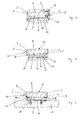
- a foam strip 2 is shown, which in the illustrated example has a rectangular cross-section, is partially surrounded by a film-like envelope 4 and is held in a pre-compressed state.
- the foam strip 2 may be formed of any open cell or closed cell flexible foam, eg polyurethane or polyethylene, and may be impregnated for a delayed recovery.
- a multilayer arrangement of a plurality of different foam materials laminated on one another is just as conceivable as the arrangement of an impregnated foam layer on or next to an unimpregnated foam layer.
- different foam layers can be arranged adjacent to each other, for example to ensure different air permeabilities of the sealing tape in the interior and exterior or a vapor diffusion gradient.
- the foam strip 2 extends in its longitudinal direction further than in its transverse direction and has two side surfaces 6 and two transverse surfaces 8, 9 (top 8 and bottom 9), which connect the two side surfaces 6.
- the material of the envelope 4 may be a sheet material, a mesh fabric, paper or other material which is suitable for the stated purpose.
- laminated films composed of a plastic film laminated with a base material (eg, nonwoven fabric) or fabric-reinforced films may also be used. All these materials are circumscribed with the term "film-like". Combinations of these materials are possible.
- a strip-shaped element 10 is arranged, which has a certain bending strength in the transverse direction.
- the bending strength should be so high that the strip-shaped element 10 absorbs the force which would result from the expansion tendency of the foam strip 2 and would normally lead to a deformation of the flexible covering 4 to a tube with an oval or even round cross-section, without the strip-shaped Element 10 itself is deformed too much.
- a foam is preferably provided, which has a higher, preferably significantly higher flexural strength than the foam strip 2. Further details will follow below.
- cardboard is an option, but all other possible rigid materials, e.g. hard plastics, usable.
- the strip-shaped element 10 should be bendable in the longitudinal direction such that the sealing strip can still be wound up into a roll.
- a tear tab 22 is provided, which is formed by two adjoining sections of the enclosure 4. It is also possible to provide only a flag-like extension of the enclosure 4. By pulling on the tear tab, the film-like wrapping 4 is opened and the expansion of the foam strip 2 is made possible.
- at least one predetermined breaking point 14, preferably a perforation line, may be provided in the wrapping 4 in the region of the side surface 6 on which the tear tab 22 protrudes.
- positions of the predetermined breaking points 14 are preferred because in this case after opening the sheath 4 no or little material remains on the left side surface 6 and a large part of the sheath 4 slides along the expanding foam strip 2 and on the right Side surface 6 arranges.
- This can be used, for example, if the envelope 4 has special sealing properties which serve for the special sealing of the right side face 6, for example in the sense of a vapor diffusion barrier.
- a number of other positions of the predetermined breaking points 14 in the invention is conceivable.
- the wrapping 4 can also be reinforced in the region adjacent to the predetermined breaking point 14, for example by thermal scorching of the film or additional application of an adhesive strip or thermal lamination of a film strip. This creates a tear limitation in the event that the enclosure 4 ruptures when cutting the desired tear 14 next to the predetermined breaking point 14 and continue to tear uncontrollably.
- the tear tab 22 can as shown on the outside (in the figures left), for reasons of better accessibility after assembly of the component 12 (eg when used in a facade or exterior wall) but also on the inside (in the figures right) may be arranged , Likewise, two tear tabs 22 may be provided on the inside and the outside for alternative opening of the enclosure 4 from inside or outside.
- a double-sided adhesive tape 16 is arranged in the illustrated example between the one transverse surface of the foam strip 2, here the bottom 9, and the strip-shaped element 10 and connects the two elements firmly together.
- the firm connection between foam strip 2 and strip-shaped element 10 can also be effected by other means, for example via thermoplastic lamination.
- a fastener 18, the attachment of the sealing tape to a component to be installed 12 is arranged in the region of the strip-shaped element 10.
- the fastening means 18 is formed as an adhesive strip, according to bottom facing outside is preferably covered by a peelable cover sheet 20, such as a silicone paper or the like, as long as the sealing tape is not attached to the component 12.
- the adhesive strip is very often realized by an adhesive layer which adheres to a silicone paper or the like and which has been laminated in this form on the strip-shaped element 10. Occasionally, a mesh fabric or a carrier film, non-woven or the like may be embedded in this adhesive layer to increase the tensile strength.
- adhesive strip used above should therefore also include adhesive layers of this type described here. The same applies to the term “adhesive tape”.
- a first portion 24 of the film-like wrapping 4 is always arranged between the first transverse surface 9 of the foam strip 2 and the strip-shaped element 10.
- the cladding covers in the example of Fig. 1, 2 and 6 the two side surfaces 6 and the top 8 of the foam strip 2 from.
- a first section 24 of the covering 4 is arranged over a partial area of the underside 9 of the foam strip 2.
- a second portion 26 of the casing 4 in a second portion of the first transverse surface, here underside 9 of the foam strip 2, which is opposite to the first portion, between the first transverse surface 9 and the strip-shaped element 10 is arranged.
- the two sections 24 and 26 of the envelope 4 thus comprise the two lower edges of the foam strip 2, are folded inwards and fastened there to the foam strip 2, preferably glued or laminated or welded to the foam strip 2.
- the bottom 9 of the foam strip 2 remains uncovered by the sheath 4.
- the adhesive tape 16 can also, as in Fig. 2 and 6 shown extending over the two sections 24, 26 of the enclosure 4.
- the sealing tape according to the invention can in principle be produced both in strip form and as a roll. In particularly rigid materials of the strip-shaped element 10, the strip shape remains as a single option.
- a component 12 is shown with attached sealing tape.
- the component 12 can be delivered as a finished kit to the site.
- the connection between the sealing strip and component 12 is produced by the fastening means 18.
- this attachment means 18 is the adhesive strip, from which the covering film 20 was previously removed.
- the attachment means 18 is a Keder- or plug-in profile, which ensures a secure connection and is preferably connected by lateral sliding or snapping with the component.
- the sealing tape is usually fastened by means of the fastening means 18 prior to installation or even before the transport of the sealed frame member 12 thereto. After installation in the appropriate building opening on site then only the sheath 4 must be opened by a knife or by pulling on the tear tab 22.
- the attached to the frame member 12 strip-shaped element 10 (which is usually not expandable) remains unchanged, while the foam strip 2 expands upwards and ensures the sealing of the joint. In the process, the part of the covering 4 remaining in the joint slides along the expanding foam strip 2 and finally, in the final state, preferably covers at least a portion of its right side surface 6.
- the first portion 24 of the envelope is disposed on the right outer edge region of the underside 9 of the foam strip 2 and firmly adhered there.
- the enclosure 4 surrounds the right side surface 6 of the foam strip 2 and at least a portion of the top 8 of the foam strip 2.
- the envelope 4 is folded over and forms a loop at the end of a second portion 26 of the enclosure 4 firmly the top 8 of the foam strip 2 is arrested. The loop thus forms the Aufgehreserve the envelope 4, corresponding to the maximum desired expansion of the foam strip. 2
- a second enclosure 28 surrounds the in Fig. 3 illustrated sealing tape.
- the sealing tape can also be produced in strip form.
- the second enclosure 28 may also have a tear tab or be accessible to any other opening mechanism.
- the second envelope 28 extends continuously along the underside of the strip-shaped element 10 and is arrested with this, for example by gluing, welding or lamination, possibly only at one or two points.
- the adhesive strip 18 for attaching the sealing tape to the component 12 is attached directly to the second enclosure 28 in this embodiment.
- the first portion 24 of the enclosure 4 is continuous between the foam strip 2 and the strip-shaped element 10.
- the attachment of the first portion 24 at the bottom 9 of the foam strip 2 via the double-sided adhesive tape 16, while another double-sided adhesive tape 27, the connection between the first section 24 of the enclosure 4 and the strip-shaped element 10 produces.
- the wrapper 4 may also be glued, welded or laminated to the foam strip 2 or the strip-shaped element 10 in another manner. As in the other embodiments (except Fig. 3 ) prevents the envelope 4, the expansion of the foam strip 2 and keeps it in the pre-compressed state.
- the foam strips 2 are usually precompressed so that they can expand when relaxing preferably to about five to ten times their occupied in the pre-compressed state thickness, but often only about half is used to secure attachment to the building part to ensure, which is opposite to the profile element to be sealed.
- a foam is preferably provided which has a higher flexural strength than the foam strip 2, usually a significantly higher bending strength.
- the strip-shaped element has a bending strength of more than 200 kPa, preferably more than 250 kPa.
- the strip-shaped element has a flexural strength of more than 300 kPa, preferably more than 400 kPa.
- the strip-shaped element has a flexural strength of more than 500 kPa, preferably more than 1,000 kPa, and more preferably more than 2,000 kPa. In this way, a deformation of the sealing tape is effectively minimized even at large widths.
- the material of the foam strip 2 on the other hand, has a flexural strength of less than 150 kPa, preferably less than 125 kPa, more preferably less than 100 kPa.
- the bending strength of the material of the strip-shaped element 10 and the foam strip 2 is determined in accordance with the standard ISO 1209-2, third edition from the year 2007. This international standard is commonly used to measure the flexural strength of plastics, but in a slightly modified form is also excellent for measuring the flexural strength of foams.
- a uniformly changed force is applied in the middle between two supports perpendicular to a sample and thus bent through.
- the flexural strength is calculated from the measured force / deformation curve (see Chapter 3 of ISO 1209-2).
- the test device is in Chapter 4, Fig. 1 shown in more detail.
- An example of the test equipment used is the type BZ2.5 / TN1S from Zwick of Ulm, Germany.
- the type KAP-Z for forces up to 200 N is used as a load cell.
- the pads consist of two parallel cylindrical support elements arranged in the same horizontal plane, each of which has a radius of (15 +/- 1) mm.
- the length of the support elements is greater than the width of the samples and is in the present case 80 mm.
- the distance L between the support elements differs from the ISO 1209-2 in the present measurement and is set to (85 +/- 2) mm.
- the power transmission element has the same shape as the support elements.
- the other sizes specified in chapter 5.1 of ISO 1209-2 are also changed for the special purpose of measuring foams.
- the first one is used, ie a measurement at (23 +/- 2) ° C and (50 +/- 10)% relative humidity.
- the in the Fig. 1 to 6 illustrated embodiments are shown in a more idealized shape of the cross section of the foam strip 2.
- the upper transverse surface 8 of the foam strip 2 is at least slightly expanded in the direction of a dome shape by the pressure acting from the inside, so that the cross-section of the foam strip 2 in the pre-compressed state assumes a certain extent, though not too different, shape from the rectangle .
- a certain transverse deflection (outer curvature) of the rigid element 10 can also be observed in practice, especially with large widths of the sealing strip.
Abstract
Description
Die Erfindung bezieht sich auf ein vorkomprimiertes Dichtband für das Abdichten einer Fuge, beispielsweise zwischen einem Rahmenprofil eines Fensters oder einer Tür und einer Gebäudewand.The invention relates to a precompressed sealing tape for sealing a joint, for example between a frame profile of a window or a door and a building wall.
Aus
Dichtbänder dieser Art werden an dem abzudichtenden Rahmenprofil angeklebt, und nach Montage des Rahmenprofils in einer Gebäudewandöffnung wird die Umhüllung aufgerissen, um es dem Schaumstoffstreifen zu ermöglichen, sich elastisch rückzustellen und damit das Rahmenprofil an der Gebäudewand abzudichten. Bei diesen bekannten Dichtbändern ist jedoch nachteilig, dass sie nur in relativ geringen Breiten hergestellt werden können, da sich ansonsten aufgrund der Rückstellkraft des vorkomprimierten Dichtbands eine ovale bis runde Form innerhalb der Umhüllung ergibt, welche für den Einbau ungeeignet ist. Im Rahmen der ständig steigenden Anforderungen an die Abdichtung in Gebäuden ist es aber wünschenswert, vorkomprimierte Dichtbänder in beliebigen Breiten bereitzustellen, um höhere Dichtwerte, eine bessere Wärmeisolierung und besseren Schallschutz zu erzielen.Sealing tapes of this type are adhered to the frame profile to be sealed, and after installation of the frame profile in a building wall opening the enclosure is torn open to allow the foam strip to resiliently reset and thus seal the frame profile on the building wall. In these known sealing tapes, however, it is disadvantageous that they can only be produced in relatively small widths, since otherwise due to the restoring force of the precompressed sealing tape, an oval to round shape results within the envelope, which is unsuitable for installation. However, in the context of ever-increasing requirements for waterproofing in buildings, it is desirable to provide precompressed sealing tapes in any widths to achieve higher sealing values, better thermal insulation and better soundproofing.
Diese Ausführungsformen besitzen den Nachteil, dass die in der Fuge verbleibende biegesteife Schicht den gehobenen Ansprüchen an Wärmeisolierung und hohe Dichtwerte nicht genügt und somit das gesamte Dichtelement im Langzeiteinsatz ungeeignet ist.These embodiments have the disadvantage that the rigid layer remaining in the joint does not meet the high demands on thermal insulation and high sealing values, and thus the entire sealing element is unsuitable for long-term use.
In
Das Problem bei dieser Ausgestaltung liegt insbesondere im großen Platzbedarf des Dichtbands zu beiden Seiten.The problem with this configuration is in particular the large space requirement of the sealing tape on both sides.
Der Erfindung liegt die Aufgabe zugrunde, ein vorkomprimiertes Dichtband zu schaffen, das einfach aufgebaut und leicht handhabbar ist, das in beliebigen Breiten geliefert werden kann und das einfacher angewendet und transportiert werden kann.The invention has for its object to provide a precompressed sealing strip which is simple and easy to handle, which can be supplied in any widths and can be applied and transported easier.
Diese Aufgabe wird durch die Merkmale des Anspruchs 1 gelöst.This object is solved by the features of claim 1.
Das erfindungsgemäße Dichtband einen elastisch rückstellfähigen, sich in Längsrichtung weiter als in Querrichtung erstreckenden Schaumstoffstreifen auf, der zwei Seitenflächen und zwei diese Seitenflächen verbindende Querflächen aufweist, außerdem eine folienhafte Umhüllung, die den Schaumstoffstreifen zumindest teilweise umgibt, und ein streifenförmiges Element, welches in Querrichtung eine höhere Biegefestigkeit aufweist als der Schaumstoffstreifen, wobei das streifenförmige Element im Bereich einer ersten Querfläche des Schaumstoffstreifens angeordnet ist. Dabei ist ein erster Abschnitt der folienhaften Umhüllung zwischen der ersten Querfläche des Schaumstoffstreifens und dem streifenförmigen Element angeordnet.The sealing strip according to the invention comprises an elastically resilient, in the longitudinal direction further than transversely extending foam strip having two side surfaces and two lateral surfaces connecting these transverse surfaces, also a film-like envelope which surrounds the foam strip at least partially, and a strip-shaped element, which in the transverse direction a has higher flexural strength than the foam strip, wherein the strip-shaped element is arranged in the region of a first transverse surface of the foam strip. In this case, a first portion of the film-like envelope between the first transverse surface of the foam strip and the strip-shaped element is arranged.
Dadurch wird gewährleistet, dass die komprimierte Rechteckform des Schaumstoffstreifens auch bei großen Breiten des Dichtbands erhalten bleibt, während der Platzbedarf des Dichtbands vor seinem Einsatz in alle Richtungen minimal ist.This ensures that the compressed rectangular shape of the foam strip is maintained even with large widths of the sealing strip, while the space requirement of the sealing strip is minimal before its use in all directions.
In einer bevorzugten Ausführungsform ist die erste Querfläche des Schaumstoffstreifens fest mit dem streifenförmigen Element verbunden. Dadurch wird eine sichere Verbindung zwischen den beiden Schichten erzeugt und ein Verrutschen der Schichten gegeneinander verhindert.In a preferred embodiment, the first transverse surface of the foam strip is fixedly connected to the strip-shaped element. This creates a secure connection between the two layers and a slipping of the layers against each other prevented.
Zur Anbringung an das abzudichtende Rahmenbauteil ist im Bereich der Seite des streifenförmigen Elements, welche der ersten Querseite des Schaumstoffstreifens abgewandt ist, ein Befestigungsmittel zur Befestigung des streifenförmigen Elements an dem Bauteil vorgesehen. Somit kann das erfindungsgemäße Dichtband bereits an dem abzudichtenden Rahmenbauteil vormontiert werden, und auf der Baustelle muss lediglich nach dem Einsetzen des Rahmenbauteils in die Gebäudeöffnung die Expansion des Schaumstoffstreifens durch Öffnen der Umhüllung ermöglicht werden.For attachment to the frame component to be sealed, a fastening means for fastening the strip-shaped element to the component is provided in the region of the side of the strip-shaped element which faces away from the first transverse side of the foam strip. Thus, the sealing tape according to the invention can already be pre-assembled on the frame member to be sealed, and on the construction site, the expansion of the foam strip by opening the enclosure must be made possible only after the insertion of the frame member in the building opening.
Eine besonders einfache Anbringung des Dichtbands am Bauteil wird erzielt, wenn das Befestigungsmittel als doppelseitiger Klebestreifen ausgebildet ist, welcher wiederum vor der Anbringung von einer Abdeckfolie überdeckt sein kann.A particularly simple attachment of the sealing tape on the component is achieved if the fastening means is designed as a double-sided adhesive strip, which in turn may be covered by a cover sheet prior to attachment.
In einer Ausgestaltung kann der erste Abschnitt der Umhüllung zwischen der ersten Querfläche des Schaumstoffstreifens und dem streifenförmigen Element durchgängig entlang der ersten Querfläche ausgebildet sein.In one embodiment, the first portion of the envelope between the first transverse surface of the foam strip and the strip-shaped element may be formed continuously along the first transverse surface.
In einer anderen Ausgestaltung kann der erste Abschnitt der Umhüllung in einem ersten Teilbereich der ersten Querfläche des Schaumstoffstreifens zwischen der ersten Querfläche und dem streifenförmigen Element angeordnet sein. Somit wird eine einfache Verbindung zwischen Schaumstoffstreifen und streifenförmigem Element möglich, weil der Großteil der ersten Querfläche des Schaumstoffstreifens als Befestigungsfläche zu Verfügung steht.In another embodiment, the first portion of the sheath may be disposed in a first portion of the first transverse surface of the foam strip between the first transverse surface and the strip-shaped element. Thus, a simple connection between foam strip and strip-shaped element is possible because the majority of the first transverse surface of the foam strip is available as a mounting surface.
In diesem Fall erreicht man eine besonders effektive Vorkomprimierung des Dichtbands, wenn ein zweiter Abschnitt der Umhüllung in einem zweiten Teilbereich der ersten Querfläche des Schaumstoffstreifens, welche dem ersten Teilbereich gegenüberliegt, zwischen der ersten Querfläche und dem streifenförmigen Element angeordnet ist.In this case, a particularly effective precompression of the sealing band is achieved if a second section of the covering is arranged in a second partial region of the first transverse surface of the foam strip, which lies opposite the first partial region, between the first transverse surface and the strip-shaped element.
Verbesserte Dichteigenschaften liefert das Dichtband, wenn das streifenförmige Element aus Schaumstoff gebildet ist und eine höhere Biegefestigkeit aufweist als der Schaumstoffstreifen.Improved sealing properties are provided by the sealing tape when the strip-shaped element is formed from foam and has a higher flexural strength than the foam strip.
Vorteilhafterweise weist das streifenförmige Element eine Biegefestigkeit von mehr als 200 kPa, bevorzugt mehr als 250 kPa, auf. In einer weiteren bevorzugten Ausführungsform weist das streifenförmige Element eine Biegefestigkeit von mehr als 300 kPa, bevorzugt mehr als 400 kPa, auf. In einer besonders bevorzugten Ausführungsform weist das streifenförmige Element eine Biegefestigkeit von mehr als 500 kPa, bevorzugt mehr als 1.000 kPa, und mehr bevorzugt mehr als 2.000 kPa auf. Auf diese Weise wird eine Verformung des Dichtbands auch bei großen Breiten effektiv minimiert.Advantageously, the strip-shaped element has a flexural strength of more than 200 kPa, preferably more than 250 kPa, on. In a further preferred embodiment, the strip-shaped element has a bending strength of more than 300 kPa, preferably more than 400 kPa. In a particularly preferred embodiment, the strip-shaped element has a flexural strength of more than 500 kPa, preferably more than 1,000 kPa, and more preferably more than 2,000 kPa. In this way, a deformation of the sealing tape is effectively minimized even at large widths.
Vorzugsweise weist die Umhüllung eine sich in Längsrichtung erstreckende Reißlasche auf, die als Zugelement zum Öffnen der Umhüllung dient. Damit kann nach der Vormontage des Dichtbands auf einem abzudichtenden Rahmenbauteil die Umhüllung auf einfache Weise durch den Anwender geöffnet werden.Preferably, the wrapper has a longitudinally extending tear tab which serves as a tension member for opening the wrapper. Thus, after the pre-assembly of the sealing tape on a frame member to be sealed, the envelope can be opened in a simple manner by the user.
Es kann jeweils vorteilhaft sein, dass die Umhüllung mit mindestens einer sich in Längsrichtung des Dichtbands erstreckenden Sollreißstelle, vorzugsweise einer Perforationslinie, versehen ist, wodurch das Öffnen der Umhüllung vereinfacht wird.It can be advantageous in each case for the sheath to be provided with at least one predetermined breaking point, preferably a perforation line, extending in the longitudinal direction of the sealing strip, whereby the opening of the sheath is simplified.
In einer Ausführungsform kann das Dichtband zu einer Rolle aufgewickelt sein, was den Transport und die Lagerung des Dichtbandes erheblich vereinfacht.In one embodiment, the sealing tape can be wound into a roll, which considerably simplifies the transport and storage of the sealing strip.
Wenn ein Bauteil bereits mit dem daran befestigten erfindungsgemäßen Dichtband ausgestattet ist, ist das Einsetzen des Bauteils auf der Baustelle besonders einfach und unkompliziert. Außerdem wird das Bauteil beim Transport zusätzlich geschützt.If a component is already equipped with the sealing tape according to the invention attached thereto, the insertion of the component on the construction site is particularly simple and straightforward. In addition, the component is additionally protected during transport.
Die Erfindung wird nachfolgend unter Bezugnahme auf in den Zeichnungen dargestellte Ausführungsformen näher erläutert.
- Fig. 1
- ist eine Querschnittsansicht einer Ausführungsform des erfindungsgemäßen vorkomprimierten Dichtbands zum Abdichten einer Fuge;
- Fig. 2
- ist eine Querschnittsansicht einer weiteren Ausführungsform des erfindungsgemäßen vorkomprimierten Dichtbands zum Abdichten einer Fuge, befestigt an einem Bauteil;
- Fig. 3
- ist eine Querschnittsansicht einer weiteren Ausführungsform des erfindungsgemäßen vorkomprimierten Dichtbands zum Abdichten einer Fuge;
- Fig. 4
- ist eine Querschnittsansicht einer weiteren Ausführungsform des erfindungsgemäßen vorkomprimierten Dichtbands zum Abdichten einer Fuge;
- Fig. 5
- ist eine Querschnittsansicht einer weiteren Ausführungsform des erfindungsgemäßen vorkomprimierten Dichtbands zum Abdichten einer Fuge; und
- Fig. 6
- ist eine Querschnittsansicht einer weiteren Ausführungsform des erfindungsgemäßen vorkomprimierten Dichtbands zum Abdichten einer Fuge, befestigt an einem Bauteil.
- Fig. 1
- Figure 11 is a cross-sectional view of one embodiment of the pre-compressed sealing tape of the invention for sealing a joint;
- Fig. 2
- is a cross-sectional view of another embodiment of the precompressed sealing tape according to the invention for sealing a joint, attached to a component;
- Fig. 3
- Figure 11 is a cross-sectional view of another embodiment of the pre-compressed sealing tape of the invention for sealing a joint;
- Fig. 4
- Figure 11 is a cross-sectional view of another embodiment of the pre-compressed sealing tape of the invention for sealing a joint;
- Fig. 5
- Figure 11 is a cross-sectional view of another embodiment of the pre-compressed sealing tape of the invention for sealing a joint; and
- Fig. 6
- is a cross-sectional view of another embodiment of the precompressed sealing tape according to the invention for sealing a joint, attached to a component.
In den Zeichnungen sind Schaumstoffstreifen, Umhüllungen, Klebebänder, streifenförmige Elemente und Abdeckfolien teilweise in einem gewissen Abstand zueinander dargestellt, um die einzelnen Elemente, die das Dichtband bilden, klar voneinander abzuheben. In Wirklichkeit liegen diese Elemente jeweils eng aufeinander auf.In the drawings, foam strips, sheaths, adhesive tapes, strip-shaped elements and cover sheets are partially shown at a certain distance from each other to clearly distinguish the individual elements that make up the sealing strip. In reality, these elements are closely related.
In
Das Material der Umhüllung 4 kann ein Folienmaterial, ein Gittergewebe, Papier oder anderes Material sein, das für den genannten Einsatzzweck geeignet ist. Außerdem sind auch laminierte Folien verwendbar, die aus einer Kunststofffolie bestehen, die mit einem Trägermaterial (z.B. Vlies) laminiert ist, oder gewebeverstärkte Folien. All diese Materialien sind mit dem Ausdruck "folienhaft" umschrieben. Auch Kombinationen dieser Materialien sind möglich. Bevorzugt ist allerdings eine thermoplastische Folie oder eine Schrumpffolie, welche sich unter Wärmeeinfluss zusammenzieht. Dieser zuletzt genannte Effekt kann auch nur in Teilen der Umhüllung 4 angewendet werden, um diese straff und faltenfrei zu machen, z.B. im Bereich der Oberseite 8 des Schaumstoffstreifens 2. Ebenso ist es möglich, dass die Umhüllung 4 lediglich im Bereich der Oberseite 8 des Schaumstoffstreifens 2 eine Verstärkung aufweist.The material of the
Im Bereich mindestens einer Querfläche, im vorliegenden Beispielsfall der Unterseite 9 des Schaumstoffstreifens 2, ist ein streifenförmiges Element 10 angeordnet, das in Querrichtung eine gewisse Biegefestigkeit aufweist. Die Biegefestigkeit sollte so hoch sein, dass das streifenförmige Element 10 die Kraft aufnimmt, welche von der Expansionsbestrebung des Schaumstoffstreifens 2 ausgeht und üblicherweise zu einer Verformung der flexiblen Umhüllung 4 hin zu einem Schlauch mit ovalem oder sogar rundem Querschnitt führen würde, ohne dass das streifenförmige Element 10 selbst zu sehr verformt wird.In the region of at least one transverse surface, in the present example, the
Als Material des streifenförmigen Elements 10 ist vorzugsweise ein Schaumstoff vorgesehen, der eine höhere, bevorzugt deutlich höhere Biegefestigkeit aufweist als der Schaumstoffstreifen 2. Näheres folgt hierzu weiter unten. Außerdem kommt beispielsweise Pappe in Frage, es sind aber auch alle anderen möglichen biegesteifen Materialien, z.B. harte Kunststoffe, verwendbar.As a material of the strip-shaped
In bestimmten Ausführungsformen sollte das streifenförmige Element 10 in Längsrichtung derart biegbar sein, dass das Dichtband noch zu einer Rolle aufgewickelt werden kann.In certain embodiments, the strip-shaped
Im Beispielsfall der
Die Umhüllung 4 kann auch im Bereich neben der Sollreißstelle 14 verstärkt sein, beispielsweise durch thermisches Veröden der Folie oder ein zusätzliches Aufbringen eines Klebestreifens oder thermisches Auflaminieren eines Folienstreifens. Dadurch entsteht eine Reißbegrenzung für den Fall, dass die Umhüllung 4 beim Durchtrennen der Sollreißstelle 14 neben der Sollreißstelle 14 aufreißt und unkontrolliert weiterreißen würde.The wrapping 4 can also be reinforced in the region adjacent to the
Ebenso ist es möglich, die Umhüllung 4 durch Zug an der Reißlasche 22 auch ohne Sollreißstelle 14 aufzureißen, wenn die Umhüllung 4 keinen großen Zugkräften widersteht, die Umhüllung 4 über einen Reißfaden aufzureißen oder die Umhüllung mit einem Messer aufzuschneiden oder mit einem anderen Hilfsmittel zu öffnen. Schließlich kann auch die gesamte Umhüllung entfernt werden, wenn die Befestigung der Umhüllung am Schaumstoffstreifen 2 oder am streifenförmigen Element 10 durch Zug lösbar ist.Likewise, it is possible to tear open the
Die Reißlasche 22 kann wie dargestellt auf der Außenseite (in den Figuren links), aus Gründen der besseren Zugänglichkeit nach der Montage des Bauteils 12 (z.B. bei Einsatz in einer Fassade oder Außenwand) aber auch auf der Innenseite (in den Figuren rechts) angeordnet sein. Ebenso können zwei Reißlaschen 22 auf der Innenseite und der Außenseite zum alternativen Öffnen der Umhüllung 4 von innen oder außen vorgesehen sein.The
Ein doppelseitiges Klebeband 16 ist im dargestellten Beispielsfall zwischen der einen Querfläche des Schaumstoffstreifens 2, hier der Unterseite 9, und dem streifenförmigen Element 10 angeordnet und verbindet die beiden Elemente fest miteinander. Die feste Verbindung zwischen Schaumstoffstreifen 2 und streifenförmigem Element 10 kann auch über andere Mittel erfolgen, beispielsweise über thermoplastisches Laminieren.A double-sided
Ein Befestigungsmittel 18, das dem Anbringen des Dichtbandes an einem einzubauenden Bauteil 12 (siehe
Es sei an dieser Stelle betont, dass in der Praxis der Klebestreifen sehr häufig durch eine Klebeschicht realisiert ist, die an einem Silikonpapier oder dergleichen haftet und die in dieser Form auf das streifenförmige Element 10 aufkaschiert worden ist. Mitunter kann in dieser Klebeschicht noch ein Gittergewebe oder eine Trägerfolie, Vlies oder dergleichen zur Vergrößerung der Zugfestigkeit eingebettet sein. Der oben verwendete Ausdruck "Klebestreifen" soll daher auch Klebeschichten dieser hier beschriebenen Art umfassen. Dasselbe trifft für den Begriff "Klebeband" zu.It should be emphasized at this point that in practice the adhesive strip is very often realized by an adhesive layer which adheres to a silicone paper or the like and which has been laminated in this form on the strip-shaped
Ein erster Abschnitt 24 der folienhaften Umhüllung 4 ist immer zwischen der ersten Querfläche 9 des Schaumstoffstreifens 2 und dem streifenförmigen Element 10 angeordnet.A
Die Umhüllung deckt im Beispiel der
Das erfindungsgemäße Dichtband kann prinzipiell sowohl in Streifenform als auch als Rolle hergestellt werden. Bei besonders biegesteifen Materialien des streifenförmigen Elements 10 bleibt die Streifenform als einzige Möglichkeit.The sealing tape according to the invention can in principle be produced both in strip form and as a roll. In particularly rigid materials of the strip-shaped
In
Das Dichtband wird üblicherweise mittels des Befestigungsmittels 18 bereits vor dem Einbau oder sogar vor dem Transport des abzudichtenden Rahmenbauteils 12 an diesem befestigt. Nach dem Einbau in die entsprechende Gebäudeöffnung vor Ort muss dann lediglich noch die Umhüllung 4 durch ein Messer oder durch Zug an der Reißlasche 22 geöffnet werden. Dabei bleibt das am Rahmenbauteil 12 befestigte streifenförmige Element 10 (welches üblicherweise nicht expansionsfähig ist) unverändert, während der Schaumstoffstreifen 2 nach oben expandiert und die Abdichtung der Fuge gewährleistet. Dabei gleitet der in der Fuge verbleibende Teil der Umhüllung 4 am expandierenden Schaumstoffstreifen 2 entlang und bedeckt schließlich im Endzustand vorzugsweise zumindest einen Abschnitt dessen rechter Seitenfläche 6.The sealing tape is usually fastened by means of the fastening means 18 prior to installation or even before the transport of the sealed
Die in
Nach dem Abwickeln des Dichtbands von der Rolle verbleibt nur soviel Zeit für das Anbringen des Dichtbands an dem Bauteil 12 und das Einsetzen des Bauteils 12 in die dafür vorgesehene Öffnung im Mauerwerk, bis die verzögerte Expansion des Schaumstoffstreifens 2 das Dichtband zu groß zum Einfügen in die Öffnung macht. Da heutige Imprägnierungen eine Verzögerung der Expansion des Schaumstoffstreifens 2 um mehrere Stunden ermöglichen, stellt dies aber keine wesentliche Einschränkung dar.After the unwinding of the sealing tape from the roller leaves only as much time for attaching the sealing tape to the
In der in
In der Ausführungsform der
Es sind noch viele andere Ausführungsformen der vorliegenden Erfindung denkbar. Die unter Bezugnahme auf
In der Praxis sind die Schaumstoffstreifen 2 meist so vorkomprimiert, dass sie beim Entspannen vorzugsweise bis auf etwa das Fünf- bis Zehnfache ihrer im vorkomprimierten Zustand eingenommenen Dicke expandieren können, wovon aber häufig nur etwa die Hälfte ausgenutzt wird, um eine sichere Anlage an dem Gebäudeteil zu gewährleisten, das dem abzudichtenden Profilelement gegenüberliegt.In practice, the foam strips 2 are usually precompressed so that they can expand when relaxing preferably to about five to ten times their occupied in the pre-compressed state thickness, but often only about half is used to secure attachment to the building part to ensure, which is opposite to the profile element to be sealed.
Als Material des streifenförmigen Elements 10 ist vorzugsweise ein Schaumstoff vorgesehen, der eine höhere Biegefestigkeit aufweist als der Schaumstoffstreifen 2, üblicherweise eine deutlich höhere Biegefestigkeit. Das streifenförmige Element hat dabei eine Biegefestigkeit von mehr als 200 kPa, bevorzugt mehr als 250 kPa. In einer bevorzugten Ausführungsform weist das streifenförmige Element eine Biegefestigkeit von mehr als 300 kPa, bevorzugt mehr als 400 kPa, auf. In einer besonders bevorzugten Ausführungsform weist das streifenförmige Element eine Biegefestigkeit von mehr als 500 kPa, bevorzugt mehr als 1.000 kPa, und mehr bevorzugt mehr als 2.000 kPa auf. Auf diese Weise wird eine Verformung des Dichtbands auch bei großen Breiten effektiv minimiert.As the material of the strip-shaped
Das Material des Schaumstoffstreifens 2 hingegen weist eine Biegefestigkeit von weniger als 150 kPa, bevorzugt weniger als 125 kPa, mehr bevorzugt weniger als 100 kPa auf.The material of the
Die Biegefestigkeit des Materials des streifenförmigen Elements 10 bzw. des Schaumstoffstreifens 2 wird dabei in Anlehnung an die Norm ISO 1209-2, dritte Ausgabe aus dem Jahr 2007, bestimmt. Diese internationale Norm wird üblicherweise zum Messen der Biegefestigkeit von Kunststoffen verwendet, eignet sich aber in etwas abgewandelter Form auch ausgezeichnet für die Messung der Biegefestigkeit von Schaumstoffen.The bending strength of the material of the strip-shaped
Hierbei wird eine gleichmäßig veränderte Kraft in der Mitte zwischen zwei Auflagen senkrecht auf eine Probe aufgebracht und diese somit durchgebogen. Aus der gemessenen Kraft-/Deformationskurve wird die Biegefestigkeit berechnet (siehe Kapitel 3 der ISO 1209-2). Die Testvorrichtung ist in Kapitel 4,
Die Auflagen bestehen aus zwei parallelen zylindrischen Auflageelementen, die in derselben horizontalen Ebene angeordnet sind und von denen jedes einen Radius von (15 +/- 1) mm aufweist. Die Länge der Auflageelemente ist größer als die Breite der Proben und beträgt im vorliegenden Fall 80 mm.The pads consist of two parallel cylindrical support elements arranged in the same horizontal plane, each of which has a radius of (15 +/- 1) mm. The length of the support elements is greater than the width of the samples and is in the present case 80 mm.
Der Abstand L zwischen den Auflageelementen weicht bei der vorliegenden Messung von der ISO 1209-2 ab und ist auf (85 +/- 2) mm festgelegt. Das Kraftübertragungselement besitzt dieselbe Form wie die Auflageelemente. Auch die übrigen in Kapitel 5.1 der ISO 1209-2 angegebenen Größenangaben werden für den speziellen Einsatzzweck der Messung von Schaumstoffen geändert. Jede gemessene Schaumstoffprobe ist ein Quader mit Länge l = (150 +/- 3) mm, Breite b = (40 +/- 2) mm und Dicke d = (3,0 +/- 0,2) mm. Von den unter Kapitel 6 der ISO 1209-2 beschriebenen Testbedingungen wird die erste verwendet, also eine Messung bei (23 +/- 2) °C und (50 +/- 10) % relativer Luftfeuchtigkeit. Entgegen dem in Kapitel 7 der ISO 1209-2 angegebenen Geschwindigkeitswert der Bewegung des Kraftübertragungselements wird dieses lediglich mit (10 +/- 1) mm pro Minute nach unten bewegt. Außerdem wird die Kraft bis zu einer maximalen Durchbiegung des Schaumstoffs von 20 mm gemessen und der im Verlauf der Messung aufgetretene Maximalwert FR der Kraft festgehalten. Die Berechnung der Biegefestigkeit R (in kPa) ergibt sich gemäß Kapitel 8.1 der ISO 1209-2 somit aus der Formel R = 1,5 FR * L / bd2 * 106, wobei FR die maximale angewandte Kraft in kN ist, L der Abstand zwischen den Auflageelementen in mm, b die Breite der Probe in mm und d die Dicke der Probe in mm.The distance L between the support elements differs from the ISO 1209-2 in the present measurement and is set to (85 +/- 2) mm. The power transmission element has the same shape as the support elements. The other sizes specified in chapter 5.1 of ISO 1209-2 are also changed for the special purpose of measuring foams. Each measured foam sample is a cuboid with length l = (150 +/- 3) mm, width b = (40 +/- 2) mm and thickness d = (3.0 +/- 0.2) mm. Of the
Bei den zuvor vorgegebenen Werten für L, b und d ergeben sich aus der gemessenen Kraft FR für das Material des streifenförmigen Elements 10 und des Schaumstoffstreifens 2 die oben genannten Werte.In the case of the previously specified values for L, b and d, the above-mentioned values result from the measured force F R for the material of the strip-shaped
Die in den
Die Erfindung wurde vorstehend am Beispiel eines Schaumstoffstreifens 1 mit rechteckigem Querschnitt beschrieben, weil dieses die Erläuterung der Erfindung und ihrer Merkmale sehr erleichtert. Mit "rechteckig" soll auch "quadratisch" umfasst sein. Der Fachmann erkennt indessen, dass sich die Erfindung in entsprechender Weise auch mit Schaumstoffstreifen 2 realisieren lässt, die vom Rechteck abweichende Querschnitte haben. Die angegebene Querschnittsgestalt des Schaumstoffstreifens 2 soll daher nicht einschränkend verstanden werden.The invention has been described above using the example of a foam strip 1 with a rectangular cross-section, because this greatly facilitates the explanation of the invention and its features. The term "rectangular" should also include "square". However, the person skilled in the art recognizes that the invention can also be implemented in a corresponding manner with
Claims (15)
einem elastisch rückstellfähigen, sich in Längsrichtung weiter als in Querrichtung erstreckenden Schaumstoffstreifen (2), der zwei Seitenflächen (6) und zwei diese Seitenflächen (6) verbindende Querflächen (8, 9) aufweist,
einer folienhaften Umhüllung (4), die den Schaumstoffstreifen (2) zumindest teilweise umgibt, und
einem streifenförmigen Element (10), welches in Querrichtung eine höhere Biegefestigkeit aufweist als der Schaumstoffstreifen (2), wobei das streifenförmige Element (10) im Bereich einer ersten Querfläche (9) des Schaumstoffstreifens (2) angeordnet ist,
dadurch gekennzeichnet, dass
ein erster Abschnitt (24) der folienhaften Umhüllung (4) zwischen der ersten Querfläche (9) des Schaumstoffstreifens (2) und dem streifenförmigen Element (10) angeordnet ist.Pre-compressed sealing tape for sealing a joint, with
an elastically resilient, longitudinally wider than transversely extending foam strip (2) having two lateral surfaces (6) and two transverse surfaces (8, 9) connecting these lateral surfaces (6),
a film-like envelope (4), which surrounds the foam strip (2) at least partially, and
a strip-shaped element (10) which has a greater bending resistance in the transverse direction than the foam strip (2), the strip-shaped element (10) being arranged in the region of a first transverse surface (9) of the foam strip (2),
characterized in that
a first portion (24) of the film-like wrapping (4) is arranged between the first transverse surface (9) of the foam strip (2) and the strip-shaped element (10).
Priority Applications (15)
| Application Number | Priority Date | Filing Date | Title |
|---|---|---|---|
| DK09178899T DK2333178T3 (en) | 2009-12-11 | 2009-12-11 | Pre-compressed sealing tape |
| PL09178899T PL2333178T3 (en) | 2009-12-11 | 2009-12-11 | Precompressed sealing tape |
| EP20090178899 EP2333178B1 (en) | 2009-12-11 | 2009-12-11 | Precompressed sealing tape |
| US12/728,808 US9540802B2 (en) | 2009-12-11 | 2010-03-22 | Precompressed sealing tape |
| DK10157518T DK2336442T3 (en) | 2009-12-11 | 2010-03-24 | Sealing tape and method for equipping a building part with this sealing tape |
| EP20100157518 EP2336442B1 (en) | 2009-12-11 | 2010-03-24 | Seal belt and method for equipping a component with same |
| PL10157518T PL2336442T3 (en) | 2009-12-11 | 2010-03-24 | Seal belt and method for equipping a component with same |
| EP20100194356 EP2336443B1 (en) | 2009-12-11 | 2010-12-09 | Seal belt and method for equipping a component with same |
| PL10194356T PL2336443T3 (en) | 2009-12-11 | 2010-12-09 | Seal belt and method for equipping a component with same |
| DK10194356T DK2336443T3 (en) | 2009-12-11 | 2010-12-09 | Sealing tape and method for equipping a building part with this sealing tape |
| DE201020017929 DE202010017929U1 (en) | 2009-12-11 | 2010-12-09 | Sealing tape for sealing a joint |
| US12/964,362 US9597832B2 (en) | 2009-12-11 | 2010-12-09 | Sealing tape |
| US14/208,613 US20140193602A1 (en) | 2009-12-11 | 2014-03-13 | Precompressed Sealing Tape |
| US14/225,873 US20140205791A1 (en) | 2009-12-11 | 2014-03-26 | Sealing Tape |
| US14/225,863 US9296150B2 (en) | 2009-12-11 | 2014-03-26 | Method for equipping a component with a sealing tape |
Applications Claiming Priority (1)
| Application Number | Priority Date | Filing Date | Title |
|---|---|---|---|
| EP20090178899 EP2333178B1 (en) | 2009-12-11 | 2009-12-11 | Precompressed sealing tape |
Publications (2)
| Publication Number | Publication Date |
|---|---|
| EP2333178A1 true EP2333178A1 (en) | 2011-06-15 |
| EP2333178B1 EP2333178B1 (en) | 2013-08-21 |
Family
ID=42184091
Family Applications (1)
| Application Number | Title | Priority Date | Filing Date |
|---|---|---|---|
| EP20090178899 Active EP2333178B1 (en) | 2009-12-11 | 2009-12-11 | Precompressed sealing tape |
Country Status (4)
| Country | Link |
|---|---|
| US (2) | US9540802B2 (en) |
| EP (1) | EP2333178B1 (en) |
| DK (1) | DK2333178T3 (en) |
| PL (1) | PL2333178T3 (en) |
Families Citing this family (5)
| Publication number | Priority date | Publication date | Assignee | Title |
|---|---|---|---|---|
| DK2138664T3 (en) * | 2008-06-23 | 2015-07-13 | Iso Chemie Gmbh | pre-compressed sealant |
| DK2584133T3 (en) | 2011-10-19 | 2014-06-23 | Iso Chemie Gmbh | Method for sealing in connection with window cleaning |
| WO2015022435A1 (en) * | 2013-08-16 | 2015-02-19 | Keylite Roof Windows Limited | An insulation member |
| EP3262131B1 (en) | 2015-02-23 | 2021-09-15 | tesa SE | Bridge tape and method for sealing holes in sheet metal or plastic parts of automobile bodies |
| US10480656B2 (en) * | 2016-08-22 | 2019-11-19 | Tesa Se | Bridge tape with directed foam expansion and method for sealing holes in sheet metal or plastic parts of automobile bodies |
Citations (5)
| Publication number | Priority date | Publication date | Assignee | Title |
|---|---|---|---|---|
| US4204373A (en) * | 1978-09-08 | 1980-05-27 | Davidson James D | Compressed expandable insulation tape and method |
| WO1998045565A1 (en) * | 1997-04-09 | 1998-10-15 | Stroemberg Johan | Sealing strip between two constructional parts |
| EP1131525B1 (en) * | 1999-09-17 | 2004-03-03 | illbruck Building Systems GmbH | Sealing strip for sealing a joint |
| US20080134595A1 (en) * | 2006-12-12 | 2008-06-12 | Pacc Systems I.P., Llc | Reinforced masonry sill and threshold sealant backer |
| EP1959065A1 (en) * | 2007-02-14 | 2008-08-20 | ISO-Chemie GmbH | Sealing tape for sealing a groove |
Family Cites Families (2)
| Publication number | Priority date | Publication date | Assignee | Title |
|---|---|---|---|---|
| US3936565A (en) * | 1974-05-03 | 1976-02-03 | Hollowform, Inc. | Molded plastic article and method |
| AU2003225704A1 (en) * | 2002-03-07 | 2003-09-22 | Sentinel Products Corp. | Polypropylene foam and foam core structure |
-
2009
- 2009-12-11 PL PL09178899T patent/PL2333178T3/en unknown
- 2009-12-11 EP EP20090178899 patent/EP2333178B1/en active Active
- 2009-12-11 DK DK09178899T patent/DK2333178T3/en active
-
2010
- 2010-03-22 US US12/728,808 patent/US9540802B2/en active Active
-
2014
- 2014-03-13 US US14/208,613 patent/US20140193602A1/en not_active Abandoned
Patent Citations (5)
| Publication number | Priority date | Publication date | Assignee | Title |
|---|---|---|---|---|
| US4204373A (en) * | 1978-09-08 | 1980-05-27 | Davidson James D | Compressed expandable insulation tape and method |
| WO1998045565A1 (en) * | 1997-04-09 | 1998-10-15 | Stroemberg Johan | Sealing strip between two constructional parts |
| EP1131525B1 (en) * | 1999-09-17 | 2004-03-03 | illbruck Building Systems GmbH | Sealing strip for sealing a joint |
| US20080134595A1 (en) * | 2006-12-12 | 2008-06-12 | Pacc Systems I.P., Llc | Reinforced masonry sill and threshold sealant backer |
| EP1959065A1 (en) * | 2007-02-14 | 2008-08-20 | ISO-Chemie GmbH | Sealing tape for sealing a groove |
Also Published As
| Publication number | Publication date |
|---|---|
| EP2333178B1 (en) | 2013-08-21 |
| PL2333178T3 (en) | 2014-01-31 |
| US20140193602A1 (en) | 2014-07-10 |
| DK2333178T3 (en) | 2013-12-02 |
| US9540802B2 (en) | 2017-01-10 |
| US20110143122A1 (en) | 2011-06-16 |
Similar Documents
| Publication | Publication Date | Title |
|---|---|---|
| EP2415942B1 (en) | Sealing tape | |
| EP2138664B1 (en) | Precompressed sealing tape | |
| EP1959065B1 (en) | Sealing tape for sealing a groove | |
| EP2333177B1 (en) | Precompressed sealing tape | |
| EP1959064B1 (en) | Resettable sealing tape | |
| EP2065548A2 (en) | Foam sealing strip | |
| EP2428632B1 (en) | Sealing tape made of soft foam | |
| EP2584134B1 (en) | Method for producing a seal in window renovation | |
| EP2666947A2 (en) | Sealing tape | |
| EP2333178B1 (en) | Precompressed sealing tape | |
| DE102011000218A1 (en) | Foam sealing strips and window frames with foam sealing strips | |
| EP2423396B1 (en) | Foam sealing strip | |
| DE4123647B4 (en) | sealing tape | |
| EP2336442B1 (en) | Seal belt and method for equipping a component with same | |
| EP3450643B2 (en) | Sealing tape roll | |
| EP3825501B1 (en) | Sealing tape | |
| EP2463060B1 (en) | Tool and method for inserting a carrier layer of a sealing strip in the grooves of a profile frame | |
| DE60209524T2 (en) | ENCAPSULATED INSULATION PRODUCT AND METHOD OF MANUFACTURING THEREOF | |
| EP3608481B1 (en) | Sealing strip roll made from a sealing strip with internal barrier layers | |
| EP3608496B1 (en) | Sealing strip roll made from a sealing strip with internal barrier layers | |
| EP3825483B1 (en) | Sealing tape | |
| EP3839187B1 (en) | Builinding section with sealing tape | |
| EP3825484A1 (en) | Sealing tape | |
| EP3825482A1 (en) | Sealing tape | |
| EP0831137A2 (en) | Tape |
Legal Events
| Date | Code | Title | Description |
|---|---|---|---|
| PUAI | Public reference made under article 153(3) epc to a published international application that has entered the european phase |
Free format text: ORIGINAL CODE: 0009012 |
|
| AK | Designated contracting states |
Kind code of ref document: A1 Designated state(s): AT BE BG CH CY CZ DE DK EE ES FI FR GB GR HR HU IE IS IT LI LT LU LV MC MK MT NL NO PL PT RO SE SI SK SM TR |
|
| AX | Request for extension of the european patent |
Extension state: AL BA RS |
|
| 17P | Request for examination filed |
Effective date: 20111209 |
|
| 17Q | First examination report despatched |
Effective date: 20120619 |
|
| GRAP | Despatch of communication of intention to grant a patent |
Free format text: ORIGINAL CODE: EPIDOSNIGR1 |
|
| INTG | Intention to grant announced |
Effective date: 20130513 |
|
| INTG | Intention to grant announced |
Effective date: 20130517 |
|
| GRAS | Grant fee paid |
Free format text: ORIGINAL CODE: EPIDOSNIGR3 |
|
| GRAA | (expected) grant |
Free format text: ORIGINAL CODE: 0009210 |
|
| AK | Designated contracting states |
Kind code of ref document: B1 Designated state(s): AT BE BG CH CY CZ DE DK EE ES FI FR GB GR HR HU IE IS IT LI LT LU LV MC MK MT NL NO PL PT RO SE SI SK SM TR |
|
| REG | Reference to a national code |
Ref country code: GB Ref legal event code: FG4D Free format text: NOT ENGLISH |
|
| REG | Reference to a national code |
Ref country code: CH Ref legal event code: EP |
|
| REG | Reference to a national code |
Ref country code: AT Ref legal event code: REF Ref document number: 628215 Country of ref document: AT Kind code of ref document: T Effective date: 20130915 |
|
| REG | Reference to a national code |
Ref country code: IE Ref legal event code: FG4D Free format text: LANGUAGE OF EP DOCUMENT: GERMAN |
|
| REG | Reference to a national code |
Ref country code: DE Ref legal event code: R096 Ref document number: 502009007824 Country of ref document: DE Effective date: 20131017 |
|
| REG | Reference to a national code |
Ref country code: DK Ref legal event code: T3 Effective date: 20131126 |
|
| REG | Reference to a national code |
Ref country code: NL Ref legal event code: T3 |
|
| REG | Reference to a national code |
Ref country code: LT Ref legal event code: MG4D |
|
| PG25 | Lapsed in a contracting state [announced via postgrant information from national office to epo] |
Ref country code: LT Free format text: LAPSE BECAUSE OF FAILURE TO SUBMIT A TRANSLATION OF THE DESCRIPTION OR TO PAY THE FEE WITHIN THE PRESCRIBED TIME-LIMIT Effective date: 20130821 Ref country code: HR Free format text: LAPSE BECAUSE OF FAILURE TO SUBMIT A TRANSLATION OF THE DESCRIPTION OR TO PAY THE FEE WITHIN THE PRESCRIBED TIME-LIMIT Effective date: 20130821 Ref country code: CY Free format text: LAPSE BECAUSE OF FAILURE TO SUBMIT A TRANSLATION OF THE DESCRIPTION OR TO PAY THE FEE WITHIN THE PRESCRIBED TIME-LIMIT Effective date: 20130724 Ref country code: NO Free format text: LAPSE BECAUSE OF FAILURE TO SUBMIT A TRANSLATION OF THE DESCRIPTION OR TO PAY THE FEE WITHIN THE PRESCRIBED TIME-LIMIT Effective date: 20131121 Ref country code: PT Free format text: LAPSE BECAUSE OF FAILURE TO SUBMIT A TRANSLATION OF THE DESCRIPTION OR TO PAY THE FEE WITHIN THE PRESCRIBED TIME-LIMIT Effective date: 20131223 Ref country code: IS Free format text: LAPSE BECAUSE OF FAILURE TO SUBMIT A TRANSLATION OF THE DESCRIPTION OR TO PAY THE FEE WITHIN THE PRESCRIBED TIME-LIMIT Effective date: 20131221 Ref country code: SE Free format text: LAPSE BECAUSE OF FAILURE TO SUBMIT A TRANSLATION OF THE DESCRIPTION OR TO PAY THE FEE WITHIN THE PRESCRIBED TIME-LIMIT Effective date: 20130821 |
|
| REG | Reference to a national code |
Ref country code: PL Ref legal event code: T3 |
|
| PG25 | Lapsed in a contracting state [announced via postgrant information from national office to epo] |
Ref country code: SI Free format text: LAPSE BECAUSE OF FAILURE TO SUBMIT A TRANSLATION OF THE DESCRIPTION OR TO PAY THE FEE WITHIN THE PRESCRIBED TIME-LIMIT Effective date: 20130821 Ref country code: FI Free format text: LAPSE BECAUSE OF FAILURE TO SUBMIT A TRANSLATION OF THE DESCRIPTION OR TO PAY THE FEE WITHIN THE PRESCRIBED TIME-LIMIT Effective date: 20130821 Ref country code: LV Free format text: LAPSE BECAUSE OF FAILURE TO SUBMIT A TRANSLATION OF THE DESCRIPTION OR TO PAY THE FEE WITHIN THE PRESCRIBED TIME-LIMIT Effective date: 20130821 |
|
| PG25 | Lapsed in a contracting state [announced via postgrant information from national office to epo] |
Ref country code: CY Free format text: LAPSE BECAUSE OF FAILURE TO SUBMIT A TRANSLATION OF THE DESCRIPTION OR TO PAY THE FEE WITHIN THE PRESCRIBED TIME-LIMIT Effective date: 20130821 |
|
| PG25 | Lapsed in a contracting state [announced via postgrant information from national office to epo] |
Ref country code: SK Free format text: LAPSE BECAUSE OF FAILURE TO SUBMIT A TRANSLATION OF THE DESCRIPTION OR TO PAY THE FEE WITHIN THE PRESCRIBED TIME-LIMIT Effective date: 20130821 Ref country code: RO Free format text: LAPSE BECAUSE OF FAILURE TO SUBMIT A TRANSLATION OF THE DESCRIPTION OR TO PAY THE FEE WITHIN THE PRESCRIBED TIME-LIMIT Effective date: 20130821 Ref country code: CZ Free format text: LAPSE BECAUSE OF FAILURE TO SUBMIT A TRANSLATION OF THE DESCRIPTION OR TO PAY THE FEE WITHIN THE PRESCRIBED TIME-LIMIT Effective date: 20130821 Ref country code: EE Free format text: LAPSE BECAUSE OF FAILURE TO SUBMIT A TRANSLATION OF THE DESCRIPTION OR TO PAY THE FEE WITHIN THE PRESCRIBED TIME-LIMIT Effective date: 20130821 |
|
| PG25 | Lapsed in a contracting state [announced via postgrant information from national office to epo] |
Ref country code: ES Free format text: LAPSE BECAUSE OF FAILURE TO SUBMIT A TRANSLATION OF THE DESCRIPTION OR TO PAY THE FEE WITHIN THE PRESCRIBED TIME-LIMIT Effective date: 20130821 |
|
| PLBE | No opposition filed within time limit |
Free format text: ORIGINAL CODE: 0009261 |
|
| STAA | Information on the status of an ep patent application or granted ep patent |
Free format text: STATUS: NO OPPOSITION FILED WITHIN TIME LIMIT |
|
| 26N | No opposition filed |
Effective date: 20140522 |
|
| PG25 | Lapsed in a contracting state [announced via postgrant information from national office to epo] |
Ref country code: MC Free format text: LAPSE BECAUSE OF FAILURE TO SUBMIT A TRANSLATION OF THE DESCRIPTION OR TO PAY THE FEE WITHIN THE PRESCRIBED TIME-LIMIT Effective date: 20130821 Ref country code: LU Free format text: LAPSE BECAUSE OF FAILURE TO SUBMIT A TRANSLATION OF THE DESCRIPTION OR TO PAY THE FEE WITHIN THE PRESCRIBED TIME-LIMIT Effective date: 20131211 |
|
| REG | Reference to a national code |
Ref country code: DE Ref legal event code: R097 Ref document number: 502009007824 Country of ref document: DE Effective date: 20140522 |
|
| REG | Reference to a national code |
Ref country code: IE Ref legal event code: MM4A |
|
| PG25 | Lapsed in a contracting state [announced via postgrant information from national office to epo] |
Ref country code: IE Free format text: LAPSE BECAUSE OF NON-PAYMENT OF DUE FEES Effective date: 20131211 |
|
| PG25 | Lapsed in a contracting state [announced via postgrant information from national office to epo] |
Ref country code: SM Free format text: LAPSE BECAUSE OF FAILURE TO SUBMIT A TRANSLATION OF THE DESCRIPTION OR TO PAY THE FEE WITHIN THE PRESCRIBED TIME-LIMIT Effective date: 20130821 |
|
| PG25 | Lapsed in a contracting state [announced via postgrant information from national office to epo] |
Ref country code: TR Free format text: LAPSE BECAUSE OF FAILURE TO SUBMIT A TRANSLATION OF THE DESCRIPTION OR TO PAY THE FEE WITHIN THE PRESCRIBED TIME-LIMIT Effective date: 20130821 |
|
| PG25 | Lapsed in a contracting state [announced via postgrant information from national office to epo] |
Ref country code: MK Free format text: LAPSE BECAUSE OF FAILURE TO SUBMIT A TRANSLATION OF THE DESCRIPTION OR TO PAY THE FEE WITHIN THE PRESCRIBED TIME-LIMIT Effective date: 20130821 Ref country code: BG Free format text: LAPSE BECAUSE OF FAILURE TO SUBMIT A TRANSLATION OF THE DESCRIPTION OR TO PAY THE FEE WITHIN THE PRESCRIBED TIME-LIMIT Effective date: 20130821 Ref country code: HU Free format text: LAPSE BECAUSE OF FAILURE TO SUBMIT A TRANSLATION OF THE DESCRIPTION OR TO PAY THE FEE WITHIN THE PRESCRIBED TIME-LIMIT; INVALID AB INITIO Effective date: 20091211 |
|
| PG25 | Lapsed in a contracting state [announced via postgrant information from national office to epo] |
Ref country code: GR Free format text: LAPSE BECAUSE OF NON-PAYMENT OF DUE FEES Effective date: 20130821 Ref country code: MT Free format text: LAPSE BECAUSE OF FAILURE TO SUBMIT A TRANSLATION OF THE DESCRIPTION OR TO PAY THE FEE WITHIN THE PRESCRIBED TIME-LIMIT Effective date: 20130821 |
|
| REG | Reference to a national code |
Ref country code: FR Ref legal event code: PLFP Year of fee payment: 7 |
|
| REG | Reference to a national code |
Ref country code: FR Ref legal event code: PLFP Year of fee payment: 8 |
|
| REG | Reference to a national code |
Ref country code: FR Ref legal event code: PLFP Year of fee payment: 9 |
|
| PGFP | Annual fee paid to national office [announced via postgrant information from national office to epo] |
Ref country code: PL Payment date: 20221201 Year of fee payment: 14 Ref country code: BE Payment date: 20221216 Year of fee payment: 14 |
|
| PGFP | Annual fee paid to national office [announced via postgrant information from national office to epo] |
Ref country code: CH Payment date: 20221229 Year of fee payment: 14 |
|
| PGFP | Annual fee paid to national office [announced via postgrant information from national office to epo] |
Ref country code: DE Payment date: 20221221 Year of fee payment: 14 |
|
| PGFP | Annual fee paid to national office [announced via postgrant information from national office to epo] |
Ref country code: GB Payment date: 20231218 Year of fee payment: 15 |
|
| PGFP | Annual fee paid to national office [announced via postgrant information from national office to epo] |
Ref country code: NL Payment date: 20231220 Year of fee payment: 15 Ref country code: IT Payment date: 20231227 Year of fee payment: 15 Ref country code: FR Payment date: 20231220 Year of fee payment: 15 Ref country code: DK Payment date: 20231218 Year of fee payment: 15 Ref country code: AT Payment date: 20231219 Year of fee payment: 15 |
|
| PGFP | Annual fee paid to national office [announced via postgrant information from national office to epo] |
Ref country code: PL Payment date: 20231201 Year of fee payment: 15 Ref country code: BE Payment date: 20231218 Year of fee payment: 15 |