EP2333152A1 - Device and method for cleaning of a filter net of a pulp dryer's fan tower, a pulp dryer's fan tower and a pulp dryer - Google Patents
Device and method for cleaning of a filter net of a pulp dryer's fan tower, a pulp dryer's fan tower and a pulp dryer Download PDFInfo
- Publication number
- EP2333152A1 EP2333152A1 EP10183678A EP10183678A EP2333152A1 EP 2333152 A1 EP2333152 A1 EP 2333152A1 EP 10183678 A EP10183678 A EP 10183678A EP 10183678 A EP10183678 A EP 10183678A EP 2333152 A1 EP2333152 A1 EP 2333152A1
- Authority
- EP
- European Patent Office
- Prior art keywords
- nozzle
- filter net
- fan tower
- cleaning
- fan
- Prior art date
- Legal status (The legal status is an assumption and is not a legal conclusion. Google has not performed a legal analysis and makes no representation as to the accuracy of the status listed.)
- Withdrawn
Links
- 238000004140 cleaning Methods 0.000 title claims abstract description 30
- 238000000034 method Methods 0.000 title claims abstract description 9
- 238000010438 heat treatment Methods 0.000 claims description 16
- 230000005540 biological transmission Effects 0.000 claims description 10
- 238000001035 drying Methods 0.000 claims description 10
- 238000010407 vacuum cleaning Methods 0.000 description 11
- XEEYBQQBJWHFJM-UHFFFAOYSA-N Iron Chemical compound [Fe] XEEYBQQBJWHFJM-UHFFFAOYSA-N 0.000 description 4
- 239000000428 dust Substances 0.000 description 3
- 238000005188 flotation Methods 0.000 description 3
- 230000008901 benefit Effects 0.000 description 2
- 229910052742 iron Inorganic materials 0.000 description 2
- 230000003247 decreasing effect Effects 0.000 description 1
- 230000001419 dependent effect Effects 0.000 description 1
- 230000006866 deterioration Effects 0.000 description 1
- 239000000835 fiber Substances 0.000 description 1
- 238000001914 filtration Methods 0.000 description 1
- 230000001771 impaired effect Effects 0.000 description 1
- 238000004519 manufacturing process Methods 0.000 description 1
- 239000000123 paper Substances 0.000 description 1
Images

Classifications
-
- B—PERFORMING OPERATIONS; TRANSPORTING
- B01—PHYSICAL OR CHEMICAL PROCESSES OR APPARATUS IN GENERAL
- B01D—SEPARATION
- B01D46/00—Filters or filtering processes specially modified for separating dispersed particles from gases or vapours
- B01D46/10—Particle separators, e.g. dust precipitators, using filter plates, sheets or pads having plane surfaces
-
- B—PERFORMING OPERATIONS; TRANSPORTING
- B01—PHYSICAL OR CHEMICAL PROCESSES OR APPARATUS IN GENERAL
- B01D—SEPARATION
- B01D46/00—Filters or filtering processes specially modified for separating dispersed particles from gases or vapours
- B01D46/66—Regeneration of the filtering material or filter elements inside the filter
- B01D46/68—Regeneration of the filtering material or filter elements inside the filter by means acting on the cake side involving movement with regard to the filter elements
- B01D46/681—Regeneration of the filtering material or filter elements inside the filter by means acting on the cake side involving movement with regard to the filter elements by scrapers, brushes or the like
-
- B—PERFORMING OPERATIONS; TRANSPORTING
- B01—PHYSICAL OR CHEMICAL PROCESSES OR APPARATUS IN GENERAL
- B01D—SEPARATION
- B01D46/00—Filters or filtering processes specially modified for separating dispersed particles from gases or vapours
- B01D46/66—Regeneration of the filtering material or filter elements inside the filter
- B01D46/68—Regeneration of the filtering material or filter elements inside the filter by means acting on the cake side involving movement with regard to the filter elements
- B01D46/682—Regeneration of the filtering material or filter elements inside the filter by means acting on the cake side involving movement with regard to the filter elements by nozzles
-
- D—TEXTILES; PAPER
- D21—PAPER-MAKING; PRODUCTION OF CELLULOSE
- D21C—PRODUCTION OF CELLULOSE BY REMOVING NON-CELLULOSE SUBSTANCES FROM CELLULOSE-CONTAINING MATERIALS; REGENERATION OF PULPING LIQUORS; APPARATUS THEREFOR
- D21C9/00—After-treatment of cellulose pulp, e.g. of wood pulp, or cotton linters ; Treatment of dilute or dewatered pulp or process improvement taking place after obtaining the raw cellulosic material and not provided for elsewhere
- D21C9/18—De-watering; Elimination of cooking or pulp-treating liquors from the pulp
-
- D—TEXTILES; PAPER
- D21—PAPER-MAKING; PRODUCTION OF CELLULOSE
- D21F—PAPER-MAKING MACHINES; METHODS OF PRODUCING PAPER THEREON
- D21F5/00—Dryer section of machines for making continuous webs of paper
- D21F5/18—Drying webs by hot air
-
- B—PERFORMING OPERATIONS; TRANSPORTING
- B01—PHYSICAL OR CHEMICAL PROCESSES OR APPARATUS IN GENERAL
- B01D—SEPARATION
- B01D2273/00—Operation of filters specially adapted for separating dispersed particles from gases or vapours
- B01D2273/28—Making use of vacuum or underpressure
Definitions
- the object of the invention is a device and a method for cleaning of a filter net of a pulp dryer's fan tower, a pulp dryer's fan tower and a pulp dryer according to the preambles of the independent claims presented below.
- the invention relates especially to a new manner of arranging vacuum-cleaning at limited areas of a pulp dryer, which are difficult to vacuum-clean, such as at the filter net of a fan tower.
- fans operating side by side are usually arranged on top of each other in order to create so called fan towers, a necessary amount of which fan towers, in turn, are arranged side by side.
- the fans are mounted in the fan tower so that their suction openings are confined to the front and back side of the fan tower, seen from the running direction of the web to be dried.
- Heating devices are arranged on the back and front sides of the fan towers, in front of the blowers' suction openings, which heating devices heat the humid air discharged from the dryer section before the fans.
- a filter net or the like In front of the heating devices, i.e. on their inlet side there is usually arranged a filter net or the like to prevent shredded paper, fibers, dust or the like from entering the heating device and the blower. Dust sticks to the filter net, which then has to be cleaned every now and then.
- the cleaning is performed e.g. once or few times a week.
- the person operating the vacuum-cleaner must, at least partly, enter the space between the fan towers, where the temperature is high, even over 100 °C, and where the humidity is also high.
- the vacuum-cleaning is usually performed with a vacuum-cleaning duct connected to the mill's central vacuum system and having a nozzle at its end. The nozzle is moved manually on the surface of the filter net to be vacuum-cleaned.
- the work is hard, very unpleasant and unergonomic.
- the Finnish patent publication FI 108882 B describes a pulp dryer's filter net, which is movable in the direction of the inlet side plane of the blast air heating device, and movable to a specific cleaning device, at least partly away from the front of the heating device's inlet side.
- the solution requires a specific mechanism for moving the filter net.
- the device and method for cleaning the filter net of a pulp dryer's fan tower, the pulp dryer's fan tower and the pulp dryer according to the invention are characterized by what is presented in the characterizing parts of the enclosed independent claims.
- a typical device according to the invention for cleaning the filter net of a pulp dryer's fan tower comprises
- a typical fan tower of a pulp dryer according to the invention comprises
- the fan tower comprises at least two superimposed fans. There may be just one fan, but usually there are several, for example three, four, five, six or even more fans on top of each other. Then it is especially advantageous if the cleaning device according to the invention is arranged to clean the filter net of the upmost fan or few upmost fans. Namely, the upmost parts of a pulp dryer usually get dirty quicker than the other parts. Thus, great benefit is gained even by a minor cleaning device investment.
- a typical pulp dryer according to the invention comprises
- a typical method according to the invention for cleaning of the filter net of a pulp dryer's fan tower comprises at least the following steps:
- a pulp dryer works more economically and reliably and with a more even capacity than before.
- Pulp dried with a pulp dryer according to the invention may even be of a more uniform quality than pulp produced with other dryers.
- Working as an operator of a pulp dryer according to the invention is safer and more comfortable than before.
- a cleaning device according to the invention can be fitted as part of a new built fan tower or pulp dryer, but it can also be retrofitted in an existing fan tower or pulp dryer.
- the filter net and the nozzle guiding means are arranged so as to be mainly vertical. Parts that are arranged in parallel are space saving and easy to build so as to be secure in operation and uniform in quality of cleaning.
- the nozzle guiding means comprise conducting means, e.g. rails or a trapezoid thread bar, and a counterpart arranged between the nozzle and the conducting means and fit for the conducting means.
- the trapezoid thread bar or the rails are a simple and reliable manner of moving the nozzles along a desired course.
- An embodiment of the invention comprises power transmission means, such as a rotatable shaft, a switch or a chain gear in order to transmit the nozzle moving power from the actuator i.e. from the power source to the nozzle.
- the power source such as a crank rotated by hand is advantageously arranged at a distance from the hot and humid space between the fan towers. Therefore, some kind of power transmission means are usually needed.
- the nozzle guiding means comprise a trapezoid thread bar arranged in connection with the filter net. Then, a counterpart connected to the nozzle and fit for the threads of the trapezoid thread bar is typically arranged between the trapezoid thread bar and the nozzle.
- a trapezoid thread bar is a very simple and reliable manner of arranging the moving of the nozzles.
- At least one wheel arranged towards the filter net is arranged in the nozzle.
- the wheel or wheels lighten the movement of the nozzle towards the filter net and reduce damage caused to the device. If a track, such as a fastening strip of the filter net's edge, is arranged over the filter net or beside it, then the wheels can be arranged to travel along this track. Thereby the rotation of the wheels can be arranged to be even lighter. At the same time, damage to the nozzle or filter net is further reduced.
- the power means comprise a connector connected to the nozzle with power transmission means and arranged to be rotatable, into which connector an actuator, such as a crank, a screw latch or an electric motor can be arranged.
- a connector of this kind is easy to arrange in a pulp dryer, for instance outside the wall, where it is easily and effortlessly rotated.
- FIG. 1 shows a conventional pulp dryer 10 comprising several adjacent fan towers 12, 12', which each have seven fans 14 placed on top of each other.
- the sides of the pulp dryer are closed with walls 16 arranged between the fan towers.
- the walls are provided with doors 18 allowing access e.g. to clean the filter nets arranged in front of the fans and heating devices.
- a pulp dryer provided with devices according to the invention would have a mainly identical side view.
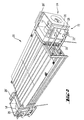
- FIG. 2 shows a part of a conventional pulp dryer.
- Fans 14, 14' are arranged on both sides of the pulp dryer's actual dryer section 20 functioning with air flotation drying.
- Vertical steam radiators 26, 26' are arranged in front of the suction openings of the fans, on the front side 22 and on the back side 24 as seen in the machine direction.
- the vertical sides of the steam radiators 26, 26' are covered with a fixed or detachable filter net 28.
- the filter net shown in Figure 2 needs to be cleaned from time to time by vacuum-cleaning the dust remaining on the surface of the net 28.
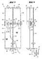
- Figure 3 shows a device 34 according to the invention for cleaning of the filter net 28 of a pulp dryer's fan tower 12, 12'.
- the filter net 28 of Figure 3 and the steam radiator 26 seen behind it have the height of two fans 14.
- the filter net can be arranged to have a desired height, for example the height of a fan tower 12, 12' comprising one or even several fans.
- the filter net and the device 34 cleaning it can have even the height of the entire fan tower 12, 12'.
- the fans are not shown in Figures 3 and 4 .
- the filter net 28 is fastened by its edges into slots of horizontal strips 36 and vertical strips 38 having a U-shaped cross-section.
- the strips 36 and 38 are fastened with bolts or other fastening means 40 to the steam radiator 26.
- the cleaning device 34 comprises a trapezoid thread bar 44 fastened with iron supports 42 to the steam radiator 26 and to the filter net 28.
- the trapezoid thread bar 44 is arranged so as to be mainly vertical and to be in the direction of the filter net 28 plane.
- the trapezoid thread bar 44 is pivoted at its ends on iron supports 42 and thereby arranged to be rotatable around its longitudinal axis.
- the trapezoid thread bar 44 has threads on its surface.
- a sleeve-like counter part 46 having on its inner surface threads fit for the threads of the trapezoid thread bar.
- a mainly horizontal nozzle packet 48 is detachably but firmly fixed in the counterpart 46.
- a nozzle packet 48 consists of one or more usually adjacent nozzles depending on the width of the surface to be vacuum-cleaned. If there are several nozzles, the nozzle packet may present an option of choosing two or even just one nozzle to be active at a time, whereby the rest of the nozzles are lifted up from the surface to be vacuum-cleaned and locked in that position with some suitable means. Then, underpressure is typically led only to the active nozzles in order to obtain the best vacuum-cleaning output. Leading of underpressure can be controlled by detaching the suction hose of the inactive nozzles' connections or by closing the valves arranged in ducts leading to these nozzles. These means for lifting, detaching and closing the nozzles and hoses are not presented.
- the nozzle packet 48 of Figures 3 and 4 has three adjacent nozzles 51, 52, 53.
- the nozzle edges provided with suction openings are close to the filter net 28 or even in touch with it. Bristles (not shown) touching the filter net can be arranged in the nozzle edge provided with suction opening.
- Connections 54, 55, 56 leading to the nozzles are shown in Figure 3 .
- a vacuum-cleaning hose 58 connected to the connections 54, 55, 56 and a branching body 60 arranged between the hose and the connections 54-56 is shown is Figure 3 .
- the nozzle packet has the width of the entire filter net 28. Both ends of the nozzle packet 48 are provided with wheels 61, which fall to the vertical fastening strips 38 of the filter net.
- the lower end 62 of the trapezoid thread bar is provided with a connector 72 into which an electric motor 64 is coupled in order to rotate said connector.
- the lower end 62 of the trapezoid thread bar is provided with a right angle gear 66 with a shaft 68 projecting therefrom.
- the shaft 68 penetrates the pulp dryer wall 16. Outside the wall at the end of the shaft 68 there is a connector 72 into which a crank 70 is arranged in the example of Figure 4 .
- the connectors 72 could also suit for example to a screw latch.
- the vacuum-cleaning device 34 When in use, the vacuum-cleaning device 34 is connected during the vacuuming action with a vacuum-cleaning hose 58 to an underpressure system, for example to the mill's central vacuum system.
- the hose 58 In order to create underpressure at the nozzles 51-53, the hose 58 is connected to the branching body 60 of the nozzle packet.
- the nozzle packet is moved vertically on the filter net 28 by rotating the trapezoid thread bar 44 around its longitudinal axis.
- the rotation power is obtained whether from the electric motor of Figure 3 or from the crank of Figure 4 , advantageously from the outside of the dryer 10.
- the rotation power can be obtained also from some other suitable source, for example from an electrical or an air-powered screw latch connected to the shaft 68 of Figure 4 .
- the wheels 61 at the edge of the nozzle packet 48 reduce the friction acting against the movement, as well as damages to the filter net 28 and the nozzles 51-53. If the wheels 61 are arranged to travel along the vertical strips 38, damage caused to the filter net 28 is further reduced.
- the nozzle packet 48 is made to move vertically up and down by changing the direction of rotation.
- Sensors or other means can be connected to the device in order to determine and fix the location of the nozzle packet 48.
- the device 34 can also be arranged to be wholly automatic so that the electric motor 64 and the cleaning are controlled by an automatic control system at certain intervals.
- Power transmission can, of course, be arranged in many different ways.
- the trapezoid thread bar can be replaced with rails along which the nozzle packet is arranged to travel.
- the travelling power of the nozzle packet can be transmitted from a power source for example via chains or cogged wheels.
- the trapezoid thread bar or some other power transmission can be covered against dirt for example with an elastic sock-type cover, for example a so-called bellows rubber. If a switch is used for power transmission, its transmission can be arranged so as to be suitable for each case.
Landscapes
- Chemical & Material Sciences (AREA)
- Chemical Kinetics & Catalysis (AREA)
- Life Sciences & Earth Sciences (AREA)
- Engineering & Computer Science (AREA)
- Wood Science & Technology (AREA)
- Paper (AREA)
Abstract
The invention relates to a device (34) and method for cleaning a vertical filter net (28) of a pulp dryer's fan tower (12,12'). The device (34) comprises at least one nozzle (51,52,53), at least one connection (54,55,56) for leading underpressure to the nozzle and means (44,46) for moving the nozzle in relation to the filter net (28). The means for moving the nozzle comprise vertical nozzle guiding means, which are arranged in connection with a filter net (28) at least mainly in an immobile manner and into which guiding means the nozzle is fixed in a mobile manner, and power means (64,66) for moving the nozzle in relation to the guiding means. The invention relates also to a fan tower (12,12') and a pulp dryer.
Description
- The object of the invention is a device and a method for cleaning of a filter net of a pulp dryer's fan tower, a pulp dryer's fan tower and a pulp dryer according to the preambles of the independent claims presented below. The invention relates especially to a new manner of arranging vacuum-cleaning at limited areas of a pulp dryer, which are difficult to vacuum-clean, such as at the filter net of a fan tower.
- A typical pulp dryer of prior art comprises
- an actual dryer section in which a pulp web is dried in air flotation drying with hot air jets or the like,
- at least one, usually several recirculation fans arranged adjacent to the actual dryer section with which recirculation fans humid air is discharged from the actual dryer section and heated air is blown as drying air into the actual dryer section, and
- heating devices with which the discharged humid air is heated before returning it as drying air into the actual dryer section.
- Several fans operating side by side are usually arranged on top of each other in order to create so called fan towers, a necessary amount of which fan towers, in turn, are arranged side by side. The fans are mounted in the fan tower so that their suction openings are confined to the front and back side of the fan tower, seen from the running direction of the web to be dried. Heating devices are arranged on the back and front sides of the fan towers, in front of the blowers' suction openings, which heating devices heat the humid air discharged from the dryer section before the fans.
- In front of the heating devices, i.e. on their inlet side there is usually arranged a filter net or the like to prevent shredded paper, fibers, dust or the like from entering the heating device and the blower. Dust sticks to the filter net, which then has to be cleaned every now and then.
- Cleaning of the filter nets of a pulp dryer's heating devices, such as steam radiators, nowadays takes place manually with a vacuum-cleaner. The cleaning is performed e.g. once or few times a week. Thus, the person operating the vacuum-cleaner must, at least partly, enter the space between the fan towers, where the temperature is high, even over 100 °C, and where the humidity is also high. The vacuum-cleaning is usually performed with a vacuum-cleaning duct connected to the mill's central vacuum system and having a nozzle at its end. The nozzle is moved manually on the surface of the filter net to be vacuum-cleaned. The work is hard, very unpleasant and unergonomic.
- Due to the reasons stated above, it is difficult to perform the vacuum-cleaning with sufficient care, and it is therefore not always done often enough. When performing the vacuum-cleaning by hand, it is also difficult to reach well enough for example behind the steam pipes, support elements, beams or the like. Inadequate vacuum-cleaning causes an increase of pressure loss and a reduction in the amount of air in the recirculation fans. This leads, in the dryer section, to an impaired air flotation ability of the pulp web, and to runnability problems. Production is naturally also decreased. Thus, this working phase should be eliminated or it should be made easier to perform.
- The Finnish patent publication
FI 108882 B - It is an aim of the present invention to reduce or even eliminate the above-mentioned problems of prior art.
- It is an aim of the present invention especially to provide a solution, with which the cleaning of the filter nets of blast air heating devices in a pulp dryer will succeed well in terms of quality without any deterioration in the working ergonomics for the user.
- In order to realise, for instance, the aims mentioned above, the device and method for cleaning the filter net of a pulp dryer's fan tower, the pulp dryer's fan tower and the pulp dryer according to the invention are characterized by what is presented in the characterizing parts of the enclosed independent claims.
- The embodiments and advantages mentioned in this text relate, where applicable, both to the device and method for cleaning the filter net of a pulp dryer's fan tower, to the pulp dryer's fan tower, as well as to the pulp dryer according to the invention, even though it is not always specifically mentioned.
- A typical device according to the invention for cleaning the filter net of a pulp dryer's fan tower comprises
- at least one nozzle,
- at least one connection, such as a hose to be connected to the vacuum system and the required connectors, for leading underpressure to the nozzle,
- a nozzle guiding means, such as a rail or a trapezoid thread bar, which is arranged in connection with the filter net at least mainly in an immobile manner and into which guiding means the nozzle is fixed in a mobile manner, and
- power means for moving the nozzle in relation to the guiding means. The power means can comprise for example the required power transmission means and connector in order to transmit the power obtained from an actuator to the power means. The actuator can be for example an electric motor or a crank.
- A typical fan tower of a pulp dryer according to the invention comprises
- at least one fan with which humid air is arranged to be discharged from the actual dryer section and with which heated air is arranged to be blown as drying air into the actual dryer section,
- a heating device, such as a steam radiator or some other suitable heat exchanger, fitted on the suction side of said at least one fan in order to reheat the humid air discharged from the actual dryer section,
- a filter net or the like, fitted in front of the heating device, on its inlet side, in order to filter the air to be heated before heating, and
- a cleaning device according to the invention in order to clean the filter net or the like.
- In a typical embodiment of the invention, the fan tower comprises at least two superimposed fans. There may be just one fan, but usually there are several, for example three, four, five, six or even more fans on top of each other. Then it is especially advantageous if the cleaning device according to the invention is arranged to clean the filter net of the upmost fan or few upmost fans. Namely, the upmost parts of a pulp dryer usually get dirty quicker than the other parts. Thus, great benefit is gained even by a minor cleaning device investment.
- A typical pulp dryer according to the invention comprises
- an actual dryer section in which a pulp web is arranged to be dried with hot air jets or the like,
- at least one fan tower according to the invention arranged adjacent to the actual dryer section, with which fan tower humid air is arranged to be discharged from the actual dryer section and with which heated air is arranged to be blown as drying air into the actual dryer section.
- A typical method according to the invention for cleaning of the filter net of a pulp dryer's fan tower comprises at least the following steps:
- Moving of one or more nozzles in relation to the filter net. Thus, the nozzle is typically moved along the filter net and in the immediate vicinity of the filter net.
- Leading of underpressure to the nozzle via one or more connections. Thus, air and dirt coming off from the filter net flows inside the nozzle through the suction opening of the nozzle. Air and dirt are led further via underpressure connections for example to a suitable filtering apparatus where dirt is removed from the air.
- Supporting of the movable nozzle with nozzle guiding means arranged in connection with the filter net at least mainly in an immobile manner. Thus, the nozzle moves in relation to the nozzle guiding means.
- Producing with power means the power needed for moving of the nozzle in relation to the filter net. Thus, the power means are functionally connected to the nozzle moved by said power means.
- With the aid of the invention, a pulp dryer works more economically and reliably and with a more even capacity than before. Pulp dried with a pulp dryer according to the invention may even be of a more uniform quality than pulp produced with other dryers. Working as an operator of a pulp dryer according to the invention is safer and more comfortable than before. A cleaning device according to the invention can be fitted as part of a new built fan tower or pulp dryer, but it can also be retrofitted in an existing fan tower or pulp dryer.
- According to an embodiment of the invention, the filter net and the nozzle guiding means are arranged so as to be mainly vertical. Parts that are arranged in parallel are space saving and easy to build so as to be secure in operation and uniform in quality of cleaning.
- According to an embodiment of the invention, the nozzle guiding means comprise conducting means, e.g. rails or a trapezoid thread bar, and a counterpart arranged between the nozzle and the conducting means and fit for the conducting means. The trapezoid thread bar or the rails are a simple and reliable manner of moving the nozzles along a desired course.
- An embodiment of the invention comprises power transmission means, such as a rotatable shaft, a switch or a chain gear in order to transmit the nozzle moving power from the actuator i.e. from the power source to the nozzle. The power source, such as a crank rotated by hand is advantageously arranged at a distance from the hot and humid space between the fan towers. Therefore, some kind of power transmission means are usually needed.
- According to an embodiment of the invention, the nozzle guiding means comprise a trapezoid thread bar arranged in connection with the filter net. Then, a counterpart connected to the nozzle and fit for the threads of the trapezoid thread bar is typically arranged between the trapezoid thread bar and the nozzle. A trapezoid thread bar is a very simple and reliable manner of arranging the moving of the nozzles.
- According to an embodiment of the invention, at least one wheel arranged towards the filter net is arranged in the nozzle. The wheel or wheels lighten the movement of the nozzle towards the filter net and reduce damage caused to the device. If a track, such as a fastening strip of the filter net's edge, is arranged over the filter net or beside it, then the wheels can be arranged to travel along this track. Thereby the rotation of the wheels can be arranged to be even lighter. At the same time, damage to the nozzle or filter net is further reduced.
- According to an embodiment of the invention, the power means comprise a connector connected to the nozzle with power transmission means and arranged to be rotatable, into which connector an actuator, such as a crank, a screw latch or an electric motor can be arranged. A connector of this kind is easy to arrange in a pulp dryer, for instance outside the wall, where it is easily and effortlessly rotated.
- The invention is described in more detail below with reference to the enclosed schematic drawing, in which
- Figure 1
- shows in a side view a typical prior art pulp dryer, wherein a device according to the invention for cleaning of the drying air can be fitted;
- Figure 2
- shows diagonally in a top view one part of a pulp dryer, wherein a conventional filter net is connected to the fan;
- Figure 3
- shows in a front view a cleaning device according to the invention mounted in connection with the drying air filter net; and
- Figure 4
- shows in a side view the cleaning device, filter net and steam radiator of
Figure 3 . -
Figure 1 shows aconventional pulp dryer 10 comprising several adjacent fan towers 12, 12', which each have sevenfans 14 placed on top of each other. The sides of the pulp dryer are closed withwalls 16 arranged between the fan towers. The walls are provided withdoors 18 allowing access e.g. to clean the filter nets arranged in front of the fans and heating devices. A pulp dryer provided with devices according to the invention would have a mainly identical side view. -
Figure 2 shows a part of a conventional pulp dryer.Fans 14, 14' are arranged on both sides of the pulp dryer'sactual dryer section 20 functioning with air flotation drying.Vertical steam radiators 26, 26' are arranged in front of the suction openings of the fans, on thefront side 22 and on theback side 24 as seen in the machine direction. The vertical sides of thesteam radiators 26, 26' are covered with a fixed ordetachable filter net 28. - Humid air flows, as shown by an
arrow 30, from the actual dryer section through thefilter net 28 and thesteam radiator 26 into thefan 14. A small amount of compensation air is absorbed also into the fan, as shown byarrows 32. The fan blows the heated air back to the actual dryer section. - The filter net shown in
Figure 2 needs to be cleaned from time to time by vacuum-cleaning the dust remaining on the surface of the net 28. The figure shows that then the operator usually has to stand in the humid, hot anddusty air flow 30. -
Figure 3 shows adevice 34 according to the invention for cleaning of thefilter net 28 of a pulp dryer'sfan tower 12, 12'. Thefilter net 28 ofFigure 3 and thesteam radiator 26 seen behind it have the height of twofans 14. The filter net can be arranged to have a desired height, for example the height of afan tower 12, 12' comprising one or even several fans. The filter net and thedevice 34 cleaning it can have even the height of theentire fan tower 12, 12'. The fans are not shown inFigures 3 and 4 . Thefilter net 28 is fastened by its edges into slots ofhorizontal strips 36 andvertical strips 38 having a U-shaped cross-section. Thestrips steam radiator 26. - The
cleaning device 34 comprises atrapezoid thread bar 44 fastened with iron supports 42 to thesteam radiator 26 and to thefilter net 28. Thetrapezoid thread bar 44 is arranged so as to be mainly vertical and to be in the direction of the filter net 28 plane. Thetrapezoid thread bar 44 is pivoted at its ends on iron supports 42 and thereby arranged to be rotatable around its longitudinal axis. Thetrapezoid thread bar 44 has threads on its surface. In the trapezoid thread bar, there is arranged a sleeve-like counter part 46 having on its inner surface threads fit for the threads of the trapezoid thread bar. A mainlyhorizontal nozzle packet 48 is detachably but firmly fixed in thecounterpart 46. - A
nozzle packet 48 according to the invention consists of one or more usually adjacent nozzles depending on the width of the surface to be vacuum-cleaned. If there are several nozzles, the nozzle packet may present an option of choosing two or even just one nozzle to be active at a time, whereby the rest of the nozzles are lifted up from the surface to be vacuum-cleaned and locked in that position with some suitable means. Then, underpressure is typically led only to the active nozzles in order to obtain the best vacuum-cleaning output. Leading of underpressure can be controlled by detaching the suction hose of the inactive nozzles' connections or by closing the valves arranged in ducts leading to these nozzles. These means for lifting, detaching and closing the nozzles and hoses are not presented. - The
nozzle packet 48 ofFigures 3 and 4 has threeadjacent nozzles Connections Figure 3 . A vacuum-cleaninghose 58 connected to theconnections body 60 arranged between the hose and the connections 54-56 is shown isFigure 3 . The nozzle packet has the width of theentire filter net 28. Both ends of thenozzle packet 48 are provided withwheels 61, which fall to the vertical fastening strips 38 of the filter net. - In
Figure 3 , thelower end 62 of the trapezoid thread bar is provided with aconnector 72 into which anelectric motor 64 is coupled in order to rotate said connector. InFigure 4 , thelower end 62 of the trapezoid thread bar is provided with aright angle gear 66 with ashaft 68 projecting therefrom. Theshaft 68 penetrates thepulp dryer wall 16. Outside the wall at the end of theshaft 68 there is aconnector 72 into which acrank 70 is arranged in the example ofFigure 4 . Theconnectors 72 could also suit for example to a screw latch. - When in use, the vacuum-cleaning
device 34 is connected during the vacuuming action with a vacuum-cleaninghose 58 to an underpressure system, for example to the mill's central vacuum system. In order to create underpressure at the nozzles 51-53, thehose 58 is connected to the branchingbody 60 of the nozzle packet. The nozzle packet is moved vertically on thefilter net 28 by rotating thetrapezoid thread bar 44 around its longitudinal axis. The rotation power is obtained whether from the electric motor ofFigure 3 or from the crank ofFigure 4 , advantageously from the outside of thedryer 10. The rotation power can be obtained also from some other suitable source, for example from an electrical or an air-powered screw latch connected to theshaft 68 ofFigure 4 . Thewheels 61 at the edge of thenozzle packet 48 reduce the friction acting against the movement, as well as damages to thefilter net 28 and the nozzles 51-53. If thewheels 61 are arranged to travel along thevertical strips 38, damage caused to thefilter net 28 is further reduced. - By rotating the
trapezoid thread bar 44 in different directions, thenozzle packet 48 is made to move vertically up and down by changing the direction of rotation. Sensors or other means can be connected to the device in order to determine and fix the location of thenozzle packet 48. Thedevice 34 can also be arranged to be wholly automatic so that theelectric motor 64 and the cleaning are controlled by an automatic control system at certain intervals. - Power transmission can, of course, be arranged in many different ways. For example, the trapezoid thread bar can be replaced with rails along which the nozzle packet is arranged to travel. The travelling power of the nozzle packet can be transmitted from a power source for example via chains or cogged wheels.
- The trapezoid thread bar or some other power transmission can be covered against dirt for example with an elastic sock-type cover, for example a so-called bellows rubber. If a switch is used for power transmission, its transmission can be arranged so as to be suitable for each case.
- Only one advantageous embodiment of the invention is shown in the figures. Facts of secondary importance regarding the main idea of the invention, facts known as such or apparent for a person skilled in the art, such as support structures possibly required by the invention, are not separately shown in the figures. It is apparent to a person skilled in the art that the invention is not limited exclusively to the examples described above, but the invention can vary within the frames of the claims presented below. The dependent claims present some possible embodiments of the invention, and they are not to be considered to restrict the scope of protection of the invention as such.
Claims (15)
- A device for cleaning a vertical filter net of a pulp dryer's fan tower, comprising- at least one nozzle,- at least one connection for leading underpressure to the nozzle,- means for moving the nozzle in relation to the filter net,
characterised in that
the means for moving the nozzle comprise- vertical nozzle guiding means, which are arranged in connection with a filter net at least mainly in an immobile manner and into which guiding means the nozzle is fixed in a mobile manner, and- power means for moving the nozzle in relation to the guiding means. - Device according to claim 1, characterised in that the nozzle guiding means comprise rails and a counterpart arranged between the nozzle and the rails, the counterpart being fit for the rails.
- Device according to claim 1, characterised in that it comprises power transmission means, such as a rotatable shaft, a gear or a chain transmission, in order to transmit the nozzle moving power from an actuator, i.e. power source, to the nozzle.
- Device according to claim 3, characterised in that the actuator is an electric motor, a screw latch or a crank.
- Device according to claim 1, characterised in that at least one wheel arranged towards the filter net is arranged in the nozzle.
- Device according to claim 1, characterised in that a track, such as a fastening strip of the filter net's edge, is arranged over the filter net or beside it, along which track the wheels are arranged to travel while the nozzle is moving.
- Device according to claim 1, characterised in that the nozzle is a nozzle packet, which consists of one or more adjacent nozzles.
- Device according to claim 1, characterised in that the device comprises sensors or other means to determine and fix the location of the nozzle.
- A fan tower of a pulp dryer comprising- at least one fan with which humid air is arranged to be discharged from the actual dryer section and with which heated air is arranged to be blown as drying air into the actual dryer section,- a heating device fitted on the suction side of said at least one fan in order to reheat the humid air discharged from the actual dryer section,- a vertical filter net or the like, fitted in front of the heating device, on its inlet side, in order to filter the air to be heated before heating, and- a cleaning device in order to clean the vertical filter net or the like, characterised in that the cleaning device is a device according to claim 1 for cleaning of the vertical filter net of a pulp dryer's fan tower.
- Fan tower according to claim 9, characterised in that it comprises at least two on top of each other, and possibly three, four, five, six or more fans on top of each other.
- Fan tower according to claim 9 or 10, characterised in that the cleaning device is arranged to be in connection with the filter net of the upmost fan of the fan tower, and possibly with the filter net of two, three, four or more upmost superimposed fans in order to clean the filter nets.
- A pulp dryer comprising- an actual dryer section in which a pulp web is arranged to be dried with hot air jets or the like,- at least one fan tower arranged adjacent to the actual dryer section, with which fan tower humid air is arranged to be discharged from the actual dryer section and with which heated air is arranged to be blown as drying air into the actual dryer section,- characterised in that the fan tower is a fan tower according to claim 9.
- A method for cleaning of a vertical filter net of a pulp dryer's fan tower comprising at least the following steps:- moving of one or more nozzles in relation to the filter net, along the filter net and in the immediate vicinity of the filter net,- leading of underpressure to the nozzle via one or more connections, whereby air and dirt coming off from the filter net flow inside the nozzle through a suction opening of the nozzle,
characterised in- supporting of the movable nozzle with vertical nozzle guiding means arranged in connection with the vertical filter net at least mainly in an immobile manner, whereby the nozzle moves in relation to the nozzle guiding means,- producing with power means the power needed for moving of the nozzle in relation to the filter net. - Method according to claim 13, characterised in that there are several nozzles, whereby- choosing two or even just one nozzle to be active at a time,- lifting up the rest of the nozzles from the surface to be cleaned and locking them in that position,- leading underpressure only to the active nozzles.
- Method according to claim 13, characterised in determining and fixing the location of the nozzle by sensors connected to the cleaning device.
Applications Claiming Priority (2)
| Application Number | Priority Date | Filing Date | Title |
|---|---|---|---|
| FI20040247U FI6403U1 (en) | 2004-06-18 | 2004-06-18 | Device for cleaning filter nets in fan tower for a pulp dryer, fan tower for pulp dryer and pulp dryer |
| EP05751780A EP1759055A1 (en) | 2004-06-18 | 2005-06-13 | Device and method for cleaning of a filter net of a pulp dryer's fan tower, a pulp dryer's fan tower and a pulp dryer |
Related Parent Applications (1)
| Application Number | Title | Priority Date | Filing Date |
|---|---|---|---|
| EP05751780.7 Division | 2005-06-13 |
Publications (1)
| Publication Number | Publication Date |
|---|---|
| EP2333152A1 true EP2333152A1 (en) | 2011-06-15 |
Family
ID=32524412
Family Applications (2)
| Application Number | Title | Priority Date | Filing Date |
|---|---|---|---|
| EP05751780A Withdrawn EP1759055A1 (en) | 2004-06-18 | 2005-06-13 | Device and method for cleaning of a filter net of a pulp dryer's fan tower, a pulp dryer's fan tower and a pulp dryer |
| EP10183678A Withdrawn EP2333152A1 (en) | 2004-06-18 | 2005-06-13 | Device and method for cleaning of a filter net of a pulp dryer's fan tower, a pulp dryer's fan tower and a pulp dryer |
Family Applications Before (1)
| Application Number | Title | Priority Date | Filing Date |
|---|---|---|---|
| EP05751780A Withdrawn EP1759055A1 (en) | 2004-06-18 | 2005-06-13 | Device and method for cleaning of a filter net of a pulp dryer's fan tower, a pulp dryer's fan tower and a pulp dryer |
Country Status (8)
| Country | Link |
|---|---|
| US (1) | US7789997B2 (en) |
| EP (2) | EP1759055A1 (en) |
| CN (1) | CN1969086B (en) |
| BR (1) | BRPI0512257A (en) |
| CA (1) | CA2568840C (en) |
| FI (1) | FI6403U1 (en) |
| RU (1) | RU77284U1 (en) |
| WO (1) | WO2005124017A1 (en) |
Cited By (1)
| Publication number | Priority date | Publication date | Assignee | Title |
|---|---|---|---|---|
| CN111486683A (en) * | 2020-04-17 | 2020-08-04 | 新沂市赛立科石英制品有限公司 | U-shaped quartz tube drying device |
Families Citing this family (22)
| Publication number | Priority date | Publication date | Assignee | Title |
|---|---|---|---|---|
| WO2009006890A1 (en) * | 2007-07-10 | 2009-01-15 | Niro A/S | A filter cleaning structure, an arrangement comprising such a filter cleaning structure, and a method of using the filter cleaning structure |
| CN101327406B (en) * | 2008-06-20 | 2011-06-08 | 北京博奇电力科技有限公司 | System and method for catalysis process of flue gas and used filtering system thereof |
| US8519357B2 (en) * | 2009-10-22 | 2013-08-27 | Anthony Peter Noto | Cleaning apparatus for sanitizing furnishings |
| US8011114B2 (en) * | 2009-12-04 | 2011-09-06 | Superior Investments, Inc. | Vehicle dryer with butterfly inlet valve |
| FI124481B (en) | 2011-03-31 | 2014-09-15 | Valmet Technologies Inc | CLEANER FAN CLEANER CLEANER, CLEANER AND MASSATOR CLEANER AND PROCEDURE CLEANER CLEANING CLEANING UNIT |
| DE102011102792A1 (en) * | 2011-05-26 | 2012-11-29 | LTG AEROB Filtration Solutions GmbH | Deposition apparatus for separating dust |
| CN104564835B (en) * | 2013-10-23 | 2016-09-14 | 际华三五一五皮革皮鞋有限公司 | Wide volume shaft type exhauster |
| US9314718B2 (en) * | 2013-11-10 | 2016-04-19 | Yamit Filtration & Water Treatment Ltd | Backwash arrangement for cleaning a cylindrical filter screen |
| CN103691218A (en) * | 2013-11-16 | 2014-04-02 | 冯晓宏 | Filter cleaning unit, self-cleaning air purification apparatus and use method thereof |
| US10591212B2 (en) * | 2014-03-12 | 2020-03-17 | Ceres | Device and method for drying grain |
| CN105057283B (en) * | 2015-08-14 | 2017-04-26 | 珠海格力电器股份有限公司 | cleaning mechanism, cleaning device and air conditioner |
| CN105617784A (en) * | 2015-12-30 | 2016-06-01 | 周桂灵 | Air filter |
| JP7679164B2 (en) * | 2018-06-29 | 2025-05-19 | 三菱重工サーマルシステムズ株式会社 | Filter cleaning unit and air conditioner |
| US11007465B2 (en) * | 2018-11-09 | 2021-05-18 | Cnh Industrial America Llc | Rotating suction wand for a non-circular air screen |
| EP3733964B1 (en) * | 2019-04-29 | 2025-10-08 | Valmet Technologies Oy | Pulp dryer |
| FI129023B (en) | 2020-04-22 | 2021-05-14 | Valmet Technologies Oy | A stationary cleaning unit and an arrangement for pulp dryer’s fan tower |
| CN113731055A (en) * | 2021-09-06 | 2021-12-03 | 朱志辉 | Environment-friendly intelligent air purification device with automatic cleaning structure |
| CN114458553B (en) * | 2021-12-24 | 2023-07-11 | 江苏海迪威液压有限公司 | Automatic lint removal device for water cooling system of wind power generating set |
| CN114635385B (en) * | 2022-03-24 | 2025-07-18 | 瑞德(新乡)路业有限公司 | Spraying dust device of washing and sweeping vehicle |
| US12350616B2 (en) * | 2022-05-31 | 2025-07-08 | The Newway Company, Inc. | Filter cleaning system for use with an external mounted filter assembly |
| CN115021104B (en) * | 2022-08-08 | 2022-11-08 | 人民电器集团(山东)枣矿智能制造有限公司 | Axial-flow type cleaning device of high-low voltage switch cabinet |
| CN117515640A (en) * | 2023-12-20 | 2024-02-06 | 华能兰州新区热电有限公司 | A regenerative flue gas waste heat recovery intermittent heating system |
Citations (4)
| Publication number | Priority date | Publication date | Assignee | Title |
|---|---|---|---|---|
| US3555785A (en) * | 1968-02-02 | 1971-01-19 | Wehr Corp | Method and means for efficiently cleaning a gas filter |
| DE2206136A1 (en) * | 1972-02-09 | 1973-08-16 | Happle & Sohn Kg Maschf | Dust filter - continuous movable cleaning device removes dust from filter surface and transports it to the dust extraction por |
| US5507851A (en) * | 1994-07-15 | 1996-04-16 | Kennington; H. L. | Filter cleaning apparatus |
| WO2000061863A1 (en) * | 1999-04-13 | 2000-10-19 | Metso Paper, Inc. | Apparatus for cleaning the drying air of a pulp dryer |
Family Cites Families (10)
| Publication number | Priority date | Publication date | Assignee | Title |
|---|---|---|---|---|
| SE196703C1 (en) | 1956-04-07 | 1965-06-15 | Svenska Flaektfabriken Ab | |
| US3233391A (en) | 1962-12-10 | 1966-02-08 | Honeywell Inc | Gas cleaning apparatus |
| GB1021638A (en) | 1963-07-12 | 1966-03-09 | Svenska Flaektfabriken Ab | Cleaning device for a gas filtering screen |
| US3991482A (en) * | 1974-08-22 | 1976-11-16 | Astec Industries, Inc. | Superheat apparatus for drying textile products |
| SU870547A2 (en) | 1980-01-25 | 1981-10-07 | Центральный Научно-Исследовательский И Проектно-Конструкторский Институт По Проектированию Оборудования Для Целлюлозно-Бумажной Промышленности | Drying section of paper-and board-making machines |
| DE3234436A1 (en) * | 1982-09-17 | 1984-03-22 | Babcock Textilmaschinen GmbH, 2105 Seevetal | Cleaning arrangement for sieves in particular in textile driers |
| SU1694474A2 (en) | 1989-12-18 | 1991-11-30 | Предприятие П/Я В-8772 | Hydraulic jack |
| US5217512A (en) * | 1992-05-28 | 1993-06-08 | Pneumafil Corporation | Apparatus for filtering debris from a moving airstream |
| US5827338A (en) * | 1997-04-03 | 1998-10-27 | Carolina Air Filtration, Inc. | Filter cleaning system including belt mounted extending nozzle |
| SE515408C2 (en) * | 1999-11-12 | 2001-07-30 | Uddevalla Mek Verkst Ab | Device and method for drying pulp webs |
-
2004
- 2004-06-18 FI FI20040247U patent/FI6403U1/en not_active IP Right Cessation
-
2005
- 2005-06-13 BR BRPI0512257-0A patent/BRPI0512257A/en not_active IP Right Cessation
- 2005-06-13 RU RU2007101731/22U patent/RU77284U1/en not_active IP Right Cessation
- 2005-06-13 WO PCT/FI2005/000271 patent/WO2005124017A1/en not_active Ceased
- 2005-06-13 EP EP05751780A patent/EP1759055A1/en not_active Withdrawn
- 2005-06-13 CA CA2568840A patent/CA2568840C/en not_active Expired - Fee Related
- 2005-06-13 US US11/629,643 patent/US7789997B2/en not_active Expired - Fee Related
- 2005-06-13 EP EP10183678A patent/EP2333152A1/en not_active Withdrawn
- 2005-06-13 CN CN2005800199476A patent/CN1969086B/en not_active Expired - Fee Related
Patent Citations (5)
| Publication number | Priority date | Publication date | Assignee | Title |
|---|---|---|---|---|
| US3555785A (en) * | 1968-02-02 | 1971-01-19 | Wehr Corp | Method and means for efficiently cleaning a gas filter |
| DE2206136A1 (en) * | 1972-02-09 | 1973-08-16 | Happle & Sohn Kg Maschf | Dust filter - continuous movable cleaning device removes dust from filter surface and transports it to the dust extraction por |
| US5507851A (en) * | 1994-07-15 | 1996-04-16 | Kennington; H. L. | Filter cleaning apparatus |
| WO2000061863A1 (en) * | 1999-04-13 | 2000-10-19 | Metso Paper, Inc. | Apparatus for cleaning the drying air of a pulp dryer |
| FI108882B (en) | 1999-04-13 | 2002-04-15 | Metso Paper Inc | Device for cleaning the drying air of a pulp dryer |
Cited By (2)
| Publication number | Priority date | Publication date | Assignee | Title |
|---|---|---|---|---|
| CN111486683A (en) * | 2020-04-17 | 2020-08-04 | 新沂市赛立科石英制品有限公司 | U-shaped quartz tube drying device |
| CN111486683B (en) * | 2020-04-17 | 2021-10-12 | 新沂市赛立科石英制品有限公司 | U-shaped quartz tube drying device |
Also Published As
| Publication number | Publication date |
|---|---|
| CN1969086A (en) | 2007-05-23 |
| BRPI0512257A (en) | 2008-02-19 |
| EP1759055A1 (en) | 2007-03-07 |
| CA2568840A1 (en) | 2005-12-29 |
| US7789997B2 (en) | 2010-09-07 |
| FIU20040247U0 (en) | 2004-06-18 |
| CA2568840C (en) | 2012-08-28 |
| CN1969086B (en) | 2010-07-21 |
| RU77284U1 (en) | 2008-10-20 |
| FI6403U1 (en) | 2004-09-30 |
| US20080011440A1 (en) | 2008-01-17 |
| WO2005124017A1 (en) | 2005-12-29 |
Similar Documents
| Publication | Publication Date | Title |
|---|---|---|
| US7789997B2 (en) | Device for cleaning of a filter net of a pulp dryer's fan tower, a pulp dryer's fan and a pulp dryer | |
| EP2691161B1 (en) | A cleaning device unit for cleaning a filter surface of a fan tower of a pulp dryer and a pulp dryer | |
| WO2018010933A1 (en) | A dust-handling device for collecting and handling dust in a paper-making environment | |
| KR101497314B1 (en) | Air handling unit | |
| CA2451913C (en) | Impingement system in the drying section of a paper machine or the like | |
| CN101466892B (en) | Hood for web forming, press and/or dryer section | |
| EP1169512B1 (en) | Apparatus for cleaning the drying air of a pulp dryer | |
| EP1736597B1 (en) | A dry end of a paper machine, an arrangement therein and a method for reducing dust spreading therein | |
| CN113522879A (en) | Device for fixing a cleaning unit and a fan tower for a pulp dryer | |
| KR20130041811A (en) | Apparatus for the heat treatment of a web of textile material | |
| CN106120424B (en) | Reequip external member, runnability component and the method for improving suction box | |
| US5451265A (en) | Method and apparatus for use in the press or dryer section of a paper machine or similar equipment | |
| CN223701918U (en) | Corrugated board production line dehumidifying device | |
| FI122925B (en) | ARRANGEMENTS AND METHOD IN CONNECTION WITH THE FIBER COURSE Blow dryer | |
| WO2001034905A1 (en) | Method and device for pulp web production | |
| CN217287680U (en) | Dust screen lifting type reverse blowing blockage removal device and corresponding closed filter cake dryer | |
| CN218812317U (en) | A raw material cleaning structure with dust removal function | |
| CN219850942U (en) | Dust removal device before painting for corrugated paper roller production | |
| CN110318193A (en) | A kind of alumina silicate gets rid of silk fiber blanket production blowning installation | |
| JPH0473290A (en) | Finishing and processing device in papermaking machine |
Legal Events
| Date | Code | Title | Description |
|---|---|---|---|
| PUAI | Public reference made under article 153(3) epc to a published international application that has entered the european phase |
Free format text: ORIGINAL CODE: 0009012 |
|
| AC | Divisional application: reference to earlier application |
Ref document number: 1759055 Country of ref document: EP Kind code of ref document: P |
|
| AK | Designated contracting states |
Kind code of ref document: A1 Designated state(s): AT SE |
|
| 17P | Request for examination filed |
Effective date: 20111213 |
|
| 17Q | First examination report despatched |
Effective date: 20120110 |
|
| STAA | Information on the status of an ep patent application or granted ep patent |
Free format text: STATUS: THE APPLICATION IS DEEMED TO BE WITHDRAWN |
|
| 18D | Application deemed to be withdrawn |
Effective date: 20120522 |