RU77284U1 - DEVICE AND METHOD OF CLEANING THE FILTER GRID COLUMN AIR PUMP DRYER PULPES, AIR COLUMN AIR PUMP DRYER PULPAS AND PULP DRYER - Google Patents
DEVICE AND METHOD OF CLEANING THE FILTER GRID COLUMN AIR PUMP DRYER PULPES, AIR COLUMN AIR PUMP DRYER PULPAS AND PULP DRYER Download PDFInfo
- Publication number
- RU77284U1 RU77284U1 RU2007101731/22U RU2007101731U RU77284U1 RU 77284 U1 RU77284 U1 RU 77284U1 RU 2007101731/22 U RU2007101731/22 U RU 2007101731/22U RU 2007101731 U RU2007101731 U RU 2007101731U RU 77284 U1 RU77284 U1 RU 77284U1
- Authority
- RU
- Russia
- Prior art keywords
- nozzle
- dryer
- filter screen
- air
- cleaning
- Prior art date
Links
- 238000004140 cleaning Methods 0.000 title claims abstract description 35
- 238000000034 method Methods 0.000 title abstract description 8
- 229920002678 cellulose Polymers 0.000 claims abstract description 31
- 239000001913 cellulose Substances 0.000 claims abstract description 31
- 238000010438 heat treatment Methods 0.000 claims description 17
- 238000001035 drying Methods 0.000 claims description 16
- 230000005540 biological transmission Effects 0.000 claims description 10
- 238000001914 filtration Methods 0.000 claims description 3
- 230000013011 mating Effects 0.000 claims 2
- 238000007664 blowing Methods 0.000 claims 1
- 238000003303 reheating Methods 0.000 claims 1
- 238000010407 vacuum cleaning Methods 0.000 description 5
- XEEYBQQBJWHFJM-UHFFFAOYSA-N Iron Chemical compound [Fe] XEEYBQQBJWHFJM-UHFFFAOYSA-N 0.000 description 4
- 239000000428 dust Substances 0.000 description 3
- 238000005188 flotation Methods 0.000 description 3
- 229910052742 iron Inorganic materials 0.000 description 2
- 230000003134 recirculating effect Effects 0.000 description 2
- 230000015556 catabolic process Effects 0.000 description 1
- 239000011248 coating agent Substances 0.000 description 1
- 238000000576 coating method Methods 0.000 description 1
- 238000006731 degradation reaction Methods 0.000 description 1
- 230000001419 dependent effect Effects 0.000 description 1
- 230000006866 deterioration Effects 0.000 description 1
- 239000000835 fiber Substances 0.000 description 1
- 238000009434 installation Methods 0.000 description 1
- 239000000123 paper Substances 0.000 description 1
Classifications
-
- B—PERFORMING OPERATIONS; TRANSPORTING
- B01—PHYSICAL OR CHEMICAL PROCESSES OR APPARATUS IN GENERAL
- B01D—SEPARATION
- B01D46/00—Filters or filtering processes specially modified for separating dispersed particles from gases or vapours
- B01D46/10—Particle separators, e.g. dust precipitators, using filter plates, sheets or pads having plane surfaces
-
- B—PERFORMING OPERATIONS; TRANSPORTING
- B01—PHYSICAL OR CHEMICAL PROCESSES OR APPARATUS IN GENERAL
- B01D—SEPARATION
- B01D46/00—Filters or filtering processes specially modified for separating dispersed particles from gases or vapours
- B01D46/66—Regeneration of the filtering material or filter elements inside the filter
- B01D46/68—Regeneration of the filtering material or filter elements inside the filter by means acting on the cake side involving movement with regard to the filter elements
- B01D46/681—Regeneration of the filtering material or filter elements inside the filter by means acting on the cake side involving movement with regard to the filter elements by scrapers, brushes or the like
-
- B—PERFORMING OPERATIONS; TRANSPORTING
- B01—PHYSICAL OR CHEMICAL PROCESSES OR APPARATUS IN GENERAL
- B01D—SEPARATION
- B01D46/00—Filters or filtering processes specially modified for separating dispersed particles from gases or vapours
- B01D46/66—Regeneration of the filtering material or filter elements inside the filter
- B01D46/68—Regeneration of the filtering material or filter elements inside the filter by means acting on the cake side involving movement with regard to the filter elements
- B01D46/682—Regeneration of the filtering material or filter elements inside the filter by means acting on the cake side involving movement with regard to the filter elements by nozzles
-
- D—TEXTILES; PAPER
- D21—PAPER-MAKING; PRODUCTION OF CELLULOSE
- D21C—PRODUCTION OF CELLULOSE BY REMOVING NON-CELLULOSE SUBSTANCES FROM CELLULOSE-CONTAINING MATERIALS; REGENERATION OF PULPING LIQUORS; APPARATUS THEREFOR
- D21C9/00—After-treatment of cellulose pulp, e.g. of wood pulp, or cotton linters ; Treatment of dilute or dewatered pulp or process improvement taking place after obtaining the raw cellulosic material and not provided for elsewhere
- D21C9/18—De-watering; Elimination of cooking or pulp-treating liquors from the pulp
-
- D—TEXTILES; PAPER
- D21—PAPER-MAKING; PRODUCTION OF CELLULOSE
- D21F—PAPER-MAKING MACHINES; METHODS OF PRODUCING PAPER THEREON
- D21F5/00—Dryer section of machines for making continuous webs of paper
- D21F5/18—Drying webs by hot air
-
- B—PERFORMING OPERATIONS; TRANSPORTING
- B01—PHYSICAL OR CHEMICAL PROCESSES OR APPARATUS IN GENERAL
- B01D—SEPARATION
- B01D2273/00—Operation of filters specially adapted for separating dispersed particles from gases or vapours
- B01D2273/28—Making use of vacuum or underpressure
Landscapes
- Chemical & Material Sciences (AREA)
- Chemical Kinetics & Catalysis (AREA)
- Life Sciences & Earth Sciences (AREA)
- Engineering & Computer Science (AREA)
- Wood Science & Technology (AREA)
- Paper (AREA)
Abstract
РЕФЕРАТESSAY
Настоящее изобретение относится к устройству (34) и способу очистки сетки (28) фильтра колонны подачи воздуха (12, 12') сушилки целлюлозы, колонне подачи воздуха и сушилке целлюлозы. Устройство (34) согласно настоящему изобретению содержит: одну или более форсунок (51-53); одну или более соединительных трубок (54-56, 58) для направления разреженного давления в форсунки; управляющие форсунками средства (44), которые предназначены для соединения с сеткой (28) фильтра, по меньшей мере, в основном неподвижным образом, и в которых форсунка закреплена с возможностью перемещения; приводные средства (44, 66, 72) для перемещения форсунки относительно управляющих средств.The present invention relates to a device (34) and a method for cleaning a filter screen (28) of an air supply column filter (12, 12 ′) of a cellulose dryer, an air supply column and a cellulose dryer. The device (34) according to the present invention comprises: one or more nozzles (51-53); one or more connecting tubes (54-56, 58) for guiding the rarefied pressure into the nozzles; nozzle-controlling means (44) that are designed to connect to the filter screen (28), at least in a substantially stationary manner, and in which the nozzle is movably mounted; drive means (44, 66, 72) for moving the nozzle relative to the control means.
(Фиг.3)(Figure 3)
Description
2420-140868RU/0822420-140868RU / 082
УСТРОЙСТВО И СПОСОБ ОЧИСТКИ СЕТКИ ФИЛЬТРА КОЛОННЫ ПОДАЧИ ВОЗДУХА СУШИЛКИ ПУЛЬПЫ, КОЛОННА ПОДАЧИ ВОЗДУХА СУШИЛКИ ПУЛЬПЫ ИDEVICE AND METHOD FOR CLEANING THE FILTER GRID COLUMN AIR PUMP DRYER PULPES, AIR COLUMN AIR PIPE DRYER PULPES AND
СУШИЛКА ПУЛЬПЫPULP DRYER
ОПИСАНИЕDESCRIPTION
Область техникиTechnical field
Объектом настоящего изобретения является устройство и способ очистки сетки фильтра колонны подачи воздуха сушилки целлюлозы, ниже представлена колонна подачи воздуха сушилки целлюлозы и сушилка целлюлозы согласно преамбуле независимых пунктов формулы изобретения. Настоящее изобретение относится к новому способу вакуумной очистки на ограниченных площадях сушилки целлюлозы, которые трудно поддаются вакуумной очистке, таких как сетка фильтра колонны подачи воздуха.The object of the present invention is a device and method for cleaning the filter screen of an air supply column of a cellulose dryer, below is an air supply column of a cellulose dryer and a cellulose dryer according to the preamble of the independent claims. The present invention relates to a new method of vacuum cleaning on limited areas of a cellulose dryer that are difficult to vacuum clean, such as an air filter column filter screen.
Уровень техникиState of the art
Типичная сушилка пульпы предшествующего уровня техники включает в себя A typical prior art pulp dryer includes
- действующую секцию сушилки, в которой полотно целлюлозы сушится флотацией потоков нагретого воздуха или тому подобного, - the current section of the dryer, in which the cellulose web is dried by flotation of heated air streams or the like,
- по меньшей мере, один, обычно несколько рециркулярных вентиляторов, расположенных рядом с действующей секцией сушилки, при помощи которых выпускается влажный воздух из действующей секции сушилки и вдувается нагретый воздух в качестве просушивающего воздуха в действующую секцию сушилки, и at least one, usually several recirculating fans, located next to the active section of the dryer, with the help of which moist air is released from the active section of the dryer and heated air is blown as drying air into the active section of the dryer, and
- нагревательные устройства, при помощи которых выпускаемый влажный воздух нагревается перед его возвратом в качестве подсушивающего воздуха в действующую секцию сушки.- heating devices by which the discharged moist air is heated before it is returned as drying air to the active drying section.
Несколько вентиляторов, работающих рядом друг с другом, обычно расположены один на другом для образования так называемой колонны подачи воздуха, в свою очередь, необходимое количество указанных колонн подачи воздуха располагается рядом друг с другом. Вентиляторы устанавливаются в колонне подачи воздуха таким образом, что их всасывающие отверстия ограничиваются передней и задней поверхностях колонны подачи воздуха, если смотреть по направлению перемещения полотна для сушки. Нагревательные устройства расположены на задней и передней поверхностях колонн подачи воздуха, перед всасывающими отверстиями нагнетателей, при этом нагревательные устройства нагревают влажный воздух, выпускаемый из секции сушки перед вентиляторами.Several fans working next to each other are usually located one on top of another to form the so-called air supply column, in turn, the required number of these air supply columns is located next to each other. Fans are installed in the air supply column in such a way that their suction openings are limited to the front and rear surfaces of the air supply column when viewed in the direction of movement of the drying web. The heating devices are located on the rear and front surfaces of the air supply columns, in front of the suction openings of the superchargers, while the heating devices heat the moist air discharged from the drying section in front of the fans.
Перед нагревательными устройствами, т.е. на их всасывающей стороне, обычно расположена сетка фильтра или тому подобное для предотвращения попадания кусочков бумаги, волокон, пыли или тому подобного в нагревательное устройство и нагнетатель. Пыль прилипает к сетке фильтра, которая затем время от времени должна быть очищена.Before heating devices, i.e. on their suction side, a filter screen or the like is usually located to prevent pieces of paper, fibers, dust or the like from getting into the heating device and blower. Dust adheres to the filter screen, which then needs to be cleaned from time to time.
Очистка сеток фильтра нагревательных устройств сушилки целлюлозы, таких как поточные радиаторы, в настоящее время производится вручную при помощи пылесоса. Очистка осуществляется, например, один раз или несколько раз в неделю. Таким образом, человек, работающий с пылесосом, должен, по меньшей мере, частично заходить в пространство между колоннами подачи воздуха, где температура высока, даже выше 100°C, и где влажность также высока. Очистка пылесосом обычно осуществляется трубкой пылесоса, подсоединенной к центральной вакуумной системе фабрики и имеющей форсунку на ее конце. Форсунка перемещается вручную по поверхности сетки фильтра для очистки пылесосом. Такая работа очень тяжела, очень неприятна и неэргономична.Cleaning the filter screens of the heating devices of the pulp dryer, such as in-line radiators, is currently done manually with a vacuum cleaner. Cleaning is carried out, for example, once or several times a week. Thus, the person working with the vacuum cleaner must at least partially enter the space between the air supply columns, where the temperature is high, even above 100 ° C, and where the humidity is also high. Vacuum cleaning is usually carried out by a vacuum cleaner tube connected to the central vacuum system of the factory and having a nozzle at its end. The nozzle moves manually on the surface of the filter screen for vacuuming. Such work is very difficult, very unpleasant and non-ergonomic.
По причинам, перечисленным выше, трудно осуществлять чистку пылесосом достаточно тщательно, и, следовательно, это происходит не всегда достаточно часто. При осуществлении чистки пылесосом вручную также трудно, например, достаточно хорошо очистить трубы потока, опорные элементы, балки и тому подобное. Недостаточная чистка пылесосом вызывает увеличение потери давления и снижение количества воздуха в рециркулирующих вентиляторах. В секции сушилки это приводит к ухудшению показателей воздушной флотации полотна целлюлозы и к проблемам функционирования. Производительность, естественно, тоже снижается. Таким образом, данная рабочая фаза должна быть исключена или она должна выполняться легче.For the reasons listed above, it is difficult to clean with a vacuum cleaner thoroughly enough, and therefore this does not always happen often enough. When carrying out manual vacuum cleaning, it is also difficult, for example, to sufficiently clean the flow pipes, support elements, beams and the like. Inadequate vacuuming causes an increase in pressure loss and a decrease in the amount of air in the recirculating fans. In the dryer section, this leads to a deterioration in the air flotation of the pulp web and to functioning problems. Performance, of course, is also declining. Thus, this working phase should be eliminated or it should be easier to carry out.
Публикация патента Финляндии FI 108882 B описывает сетку фильтра сушилки целлюлозы, которая перемещается в направлении плоскости всасывающей стороны воздуходувного нагревательного устройства, и может перемещаться к определенному очищающему устройству, по меньшей мере, частично в стороне от передней части всасывающей стороны нагревательного устройства. Такое решение требует специального механизма для перемещения сетки фильтра.Finnish Publication FI 108882 B describes a filter screen of a cellulose dryer that moves in the direction of the plane of the suction side of the blower heating device and can move to a specific cleaning device at least partially away from the front of the suction side of the heating device. This solution requires a special mechanism for moving the filter mesh.
Цель и описание настоящего изобретенияPurpose and description of the present invention
Целью настоящего изобретения является снижение или даже исключение упомянутых выше проблем предшествующего уровня техники.The aim of the present invention is to reduce or even eliminate the above-mentioned problems of the prior art.
В частности, целью настоящего изобретения является обеспечение решения, при котором очистка сеток фильтра воздуходувного нагревательного устройства в сушилке целлюлозы будет прекрасно достигаться, исходя из качества, без какого-либо ухудшения в эргономике работы для пользователя.In particular, it is an object of the present invention to provide a solution in which cleaning filter screens of a blower heating device in a cellulose dryer will be excellently achieved based on quality without any degradation in user ergonomics.
Например, для достижения целей, упомянутых выше, устройство и способ очистки сетки фильтра колонны подачи воздуха сушилки целлюлозы, колонна подачи воздуха и сушилка целлюлозы согласно настоящему изобретению, отличаются тем, что показано в отличительной части независимых пунктов приложенной формулы изобретения.For example, in order to achieve the objectives mentioned above, the apparatus and method for cleaning the filter screen of an air supply column of a cellulose dryer, an air supply column and a cellulose dryer of the present invention are different from those shown in the characterizing part of the independent claims.
Варианты воплощения настоящего изобретения и преимущества, упомянутые в тексте, относятся, по возможности, как к устройству и способу очистки сетки фильтра колонны подачи воздуха сушилки целлюлозы, колонне подачи воздуха сушилки целлюлозы, так и к сушилке целлюлозы согласно настоящему изобретению, даже если это не всегда отдельно упомянуто.Embodiments of the present invention and the advantages mentioned in the text relate, as far as possible, to both the device and method of cleaning the filter screen of the air supply column of the cellulose dryer, the air supply column of the cellulose dryer, and the cellulose dryer according to the present invention, even if not always separately mentioned.
Обычное устройство согласно настоящему изобретению для очистки сетки фильтра колонны подачи воздуха сушилки целлюлозы включает в себя A conventional apparatus according to the present invention for cleaning a filter screen of an air supply column of a pulp dryer includes
- по меньшей мере, одну форсунку, - at least one nozzle,
- по меньшей мере одну соединительную трубку, такую как шланг для присоединения к вакуумной системе, и необходимые коннекторы для направления разреженного давления к форсунке, at least one connecting tube, such as a hose for connection to a vacuum system, and the necessary connectors for directing the rarefied pressure to the nozzle,
- средства перемещения форсунки, такие как рельс или стержень с трапециидальной резьбой, который предназначен для соединения с сеткой фильтра в основном, по меньшей мере, неподвижным образом, в котором форсунка закрепляется с возможностью перемещения, и - nozzle moving means, such as a rail or a trapezoidal threaded rod, which is intended to be connected to the filter screen in a substantially at least fixed manner in which the nozzle is movably fixed, and
- приводные средства для перемещения форсунки относительно направляющих средств. Приводные средства могут содержать, например, необходимые средства передачи мощности и коннектор для передачи полученной от привода мощности к приводным средствам. Например, приводом может быть электрический мотор или кривошип.- drive means for moving the nozzle relative to the guide means. The drive means may comprise, for example, the necessary power transmission means and a connector for transmitting the power received from the drive to the drive means. For example, the drive may be an electric motor or crank.
Типичная колонна подачи воздуха сушилки целлюлозы согласно настоящему изобретению включает в себя A typical pulp dryer air supply column according to the present invention includes
- по меньшей мере, один вентилятор, при помощи которого влажный воздух выдувается из действующей секции сушилки и при помощи которого нагретый воздух вдувается в качестве подсушивающего воздуха в действующую секцию сушилки, - at least one fan by means of which moist air is blown out of the active section of the dryer and by which heated air is blown as drying air into the active section of the dryer,
- нагревательное устройство, такое как поточный радиатор или какой-либо другой соответствующий теплообменник, установленный на всасывающей стороне упомянутого, по меньшей мере, одного вентилятора для повторного нагрева влажного воздуха, выдуваемого из действующей секции сушки, - a heating device, such as a flow radiator or some other suitable heat exchanger mounted on the suction side of said at least one fan to reheat moist air blown out of the existing drying section,
- сетку фильтра или тому подобное, установленную перед нагревательным устройством, на его всасывающей стороне, для фильтрации воздуха, предназначенного для нагрева, перед нагреванием, и - a filter screen or the like, installed in front of the heating device, on its suction side, for filtering air intended for heating, before heating, and
- очистительное устройство согласно настоящему изобретению для очистки сетки фильтра или тому подобное.- a cleaning device according to the present invention for cleaning a filter screen or the like.
В типичном варианте воплощения настоящего изобретения колонна подачи воздуха включает в себя, по меньшей мере, два расположенных друг над другом вентилятора. Это может быть только один вентилятор, но обычно несколько, например, три, четыре, пять, шесть или даже больше вентиляторов, установленных один над другим. Особенно предпочтительно, чтобы очистительное устройство согласно настоящему изобретению, было предназначено для очистки сетки фильтра верхнего вентилятора или нескольких верхних вентиляторов. А именно, верхние части сушилки целлюлозы обычно загрязняются быстрее, чем другие части. Таким образом, большое преимущество достигается даже при несущественных вложениях в очистительное устройство.In a typical embodiment of the present invention, the air supply column includes at least two superposed fans. It can be only one fan, but usually several, for example, three, four, five, six or even more fans installed one above the other. It is particularly preferred that the cleaning device according to the present invention is for cleaning the filter screen of the top fan or several top fans. Namely, the upper parts of the cellulose dryer are usually contaminated faster than other parts. Thus, a great advantage is achieved even with insignificant investments in the cleaning device.
Типичная сушилка целлюлозы согласно настоящему изобретению включает в себя A typical cellulose dryer according to the present invention includes
- действующую секцию сушилки, в которой расположено полотно целлюлозы, предназначенное для сушки потоками горячего воздуха, или тому подобное, - the current section of the dryer, in which there is a cellulose web intended for drying by streams of hot air, or the like,
- по меньшей мере, одну колонну подачи воздуха согласно настоящему изобретению, расположенную рядом с действующей секцией сушилки, в которой влажный воздух колонны подачи воздуха выдувается из действующей секции сушилки и в которой нагретый воздух вдувается в качестве подсушивающего воздуха в действующую секцию сушилки.- at least one air supply column according to the present invention, located next to the active section of the dryer, in which the moist air of the air supply column is blown out of the active section of the dryer and in which heated air is blown as drying air into the active section of the dryer.
Согласно типичному способу согласно настоящему изобретению для очистки сетки фильтра колонны подачи воздуха сушилки целлюлозы, по меньшей мере, According to a typical method according to the present invention for cleaning the filter screen of an air column of a pulp dryer at least
- перемещают одну или более форсунок относительно сетки фильтра. Таким образом, форсунка, как правило, перемещается вдоль сетки фильтра и в непосредственной близости от сетки фильтра,- move one or more nozzles relative to the filter mesh. Thus, the nozzle, as a rule, moves along the filter screen and in the immediate vicinity of the filter screen,
- направляют разреженное давление к форсунке посредством одного или более коннекторов. Таким образом, воздух и грязь, выходящие из сетки фильтра, поступают в форсунку через всасывающее отверстие форсунки. Воздух и загрязнения проходят дополнительно через коннекторы разреженного давления, например, к соответствующим фильтрующим аппаратам, в которых загрязнения удаляются из воздуха,- direct the rarefied pressure to the nozzle by means of one or more connectors. Thus, air and dirt coming out of the filter screen enter the nozzle through the suction nozzle of the nozzle. Air and pollution pass in addition through rarefied pressure connectors, for example, to the corresponding filtering devices in which pollution are removed from air,
- поддерживают перемещающуюся форсунку при помощи направляющих форсунку средств, расположенных в соединении с сеткой фильтра, по меньшей мере, в основном неподвижным образом. Таким образом, форсунка перемещается относительно направляющих форсунку средств,- supporting the moving nozzle by means of nozzle guiding means located in connection with the filter screen, at least in a substantially stationary manner. Thus, the nozzle moves relative to the means guiding the nozzle,
- производят с помощью приводных средств мощность, необходимую для перемещения форсунки относительно сетки фильтра. Таким образом, приводные средства функционально связаны с форсункой, перемещаемой упомянутыми приводными средствами.- using power means, produce the power necessary to move the nozzle relative to the filter screen. Thus, the drive means are operatively coupled to a nozzle moved by said drive means.
Согласно цели настоящего изобретения, сушилка целлюлозы работает более экономично и надежно и с большей производительностью, чем ранее. Целлюлоза, которая сушится посредством сушилки целлюлозы согласно настоящему изобретению, может быть даже более однородного качества, чем целлюлоза, производимая другими сушилками. Работа оператора сушилки целлюлозы согласно настоящему изобретению является более безопасной и более удобной, чем ранее. Очистительное устройство согласно настоящему изобретению может устанавливаться как часть вновь созданной колонны подачи воздуха или сушилки целлюлозы, но также может быть проведет ретрофиттинг имеющейся колонны подачи воздуха или сушилки целлюлозы.According to the purpose of the present invention, the pulp dryer is more economical and reliable and with greater productivity than before. Cellulose that is dried by the cellulose dryer of the present invention can be of even more uniform quality than the cellulose produced by other dryers. The operation of the pulp dryer operator of the present invention is safer and more convenient than before. A cleaning device according to the present invention can be installed as part of a newly created air supply column or cellulose dryer, but can also retrofit an existing air supply column or cellulose dryer.
Согласно варианту воплощения настоящего изобретения, сетка фильтра и направляющие форсунку средства расположены в основном вертикально. Части, расположенные параллельно, экономят пространство и легко монтируются так, чтобы соблюдалась безопасность работы и постоянство качества очистки.According to an embodiment of the present invention, the filter screen and nozzle guiding means are arranged substantially vertically. Parts located in parallel save space and are easy to install so that safe operation and consistent cleaning quality are maintained.
Согласно варианту воплощения настоящего изобретения, направляющие форсунку средства включают в себя проводящие средства, например, рельсы или стержень с трапециидальной резьбой, и ответную часть, расположенную между форсункой и проводящими средствами и соответствующую проводящим средствам.According to an embodiment of the present invention, nozzle-guiding means include conductive means, for example, rails or a trapezoidal threaded rod, and a counterpart located between the nozzle and the conductive means and corresponding to the conductive means.
Стержень с трапециидальной резьбой или рельсы являются простым и надежным способом для перемещения форсунки по заданному направлению.Trapezoidal threaded rod or rails are a simple and reliable way to move the nozzle in a given direction.
Вариант воплощения настоящего изобретения включает в себя средства передачи мощности, такие как поворотный вал, переключатель или цепную передачу для передачи мощности для перемещения форсунки от привода, например, источника мощности, к форсунке. Источник мощности, такой как кривошип, вращаемый рукой, преимущественно расположен на расстоянии от горячей и влажной области между колоннами подачи воздуха. Следовательно, обычно необходимы какие-то виды средств передачи мощности.An embodiment of the present invention includes power transmission means, such as a rotary shaft, a switch, or a chain transmission for transmitting power to move the nozzle from a drive, such as a power source, to the nozzle. A power source, such as a crank rotated by hand, is preferably located at a distance from the hot and humid area between the air supply columns. Therefore, some kind of power transmission means is usually needed.
Согласно варианту воплощения настоящего изобретения, направляющие форсунку средства включают в себя стержень с трапециидальной резьбой, расположенный в соединении с сеткой фильтра. Затем ответная часть, присоединенная к форсунке и соответствующая резьбе стержня с трапециидальной резьбой, обычно расположена между стержнем с трапециидальной резьбой и форсункой. Стержень с трапециидальной резьбой является очень простым и надежным способом осуществления перемещения форсунок.According to an embodiment of the present invention, the nozzle guiding means include a trapezoidal threaded rod located in connection with the filter screen. Then, the counterpart attached to the nozzle and corresponding to the thread of the trapezoidal threaded rod is usually located between the trapezoidal threaded rod and the nozzle. A trapezoidal threaded rod is a very simple and reliable way of moving nozzles.
Согласно варианту воплощения настоящего изобретения, по меньшей мере, одно колесо, расположенное по направлению к сетке фильтра, находится в форсунке. Колесо или колеса упрощают перемещение форсунки к сетке фильтра и снижают повреждения, причиняемые устройству. Если по сетке фильтра или рядом с ней выполнена направляющая, такая как прикрепленная полоска или край сетки фильтра, то колеса могут быть приспособлены для перемещения по такой направляющей. According to an embodiment of the present invention, at least one wheel located towards the filter screen is in the nozzle. A wheel or wheels simplifies the movement of the nozzle to the filter screen and reduces damage to the device. If a guide is made along or adjacent to the filter screen, such as an attached strip or the edge of the filter screen, the wheels can be adapted to move along such a track.
Таким образом, поворот колес может осуществляться очень легко. В то же время повреждение форсунки или сетки фильтра дополнительно снижаются.Thus, turning the wheels can be very easy. At the same time, damage to the nozzle or filter screen is further reduced.
Согласно варианту воплощения настоящего изобретения, приводные средства включают в себя коннектор, соединенный с форсункой средствами передачи мощности и являющийся поворотным, в таком коннекторе может предусматриваться привод, такой как кривошип, винтовой ригель или электрический мотор. Коннектор такого типа легко располагается в сушилке целлюлозы, например, на наружной стороне стены, где он легко и без усилий может поворачиваться.According to an embodiment of the present invention, the drive means include a connector connected to the nozzle by means of power transmission and being rotatable, a drive such as a crank, a screw bolt or an electric motor may be provided in such a connector. A connector of this type is easily located in a cellulose dryer, for example, on the outside of the wall, where it can be easily and effortlessly rotated.
Краткое описание чертежейBrief Description of the Drawings
Настоящее изобретение описано более подробно ниже со ссылкой на прилагаемые схематические чертежи, в которых The present invention is described in more detail below with reference to the accompanying schematic drawings, in which
Фиг.1 показывает вид сбоку типичной сушки целлюлозы предшествующего уровня техники, в которой может быть установлено устройство согласно настоящему изобретению для очистки подсушивающего воздуха; Figure 1 shows a side view of a typical prior art pulp drying in which the apparatus of the present invention for purifying drying air can be installed;
Фиг.2 показывает диагонально на виде сверху одну часть сушилки целлюлозы, в которой традиционная сетка фильтра присоединена к вентилятору; Figure 2 shows, diagonally in a plan view, one part of a cellulose dryer in which a conventional filter screen is connected to a fan;
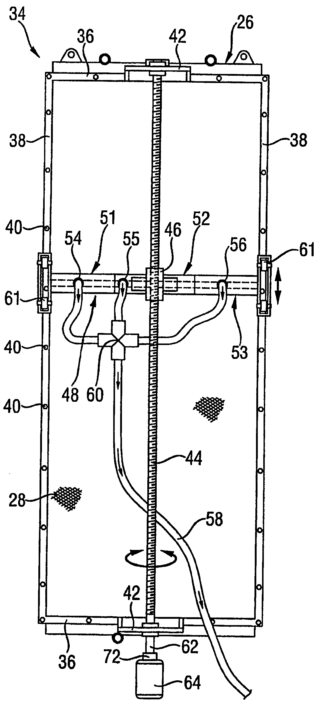
Фиг.3 показывает вид спереди очистительного устройства согласно настоящему изобретению, присоединенного к сетке фильтра подсушивающего воздуха; и Figure 3 shows a front view of a cleaning device according to the present invention attached to a filter grid of drying air; and
Фиг.4 показывает вид сбоку очистительного устройства, сетки фильтра и поточного радиатора на Фиг.3.Figure 4 shows a side view of the cleaning device, the filter screen and the flow radiator in Figure 3.
Подробное описание вариантов воплощения на чертежахDetailed Description of Embodiments in Drawings
Фиг.1 показывает традиционную сушилку 10 целлюлозы, включающую в себя несколько расположенных рядом колонн 12, 12' подачи воздуха, каждая из которых содержит семь вентиляторов 14, расположенных один над другим. Стороны сушилки целлюлозы закрыты стенками 16, расположенными между колоннами подачи воздуха.Figure 1 shows a conventional pulp dryer 10, including several adjacent air supply columns 12, 12 ', each of which contains seven fans 14 located one above the other. The sides of the cellulose dryer are covered by walls 16 located between the air supply columns.
На стенках находятся дверцы 18 для обеспечения доступа, т.е. для очистки сеток фильтра, расположенных перед вентиляторами и нагревательными устройствами. Сушилка целлюлозы с устройствами согласно настоящему изобретению будет иметь, в основном, идентичный вид сбоку.On the walls there are doors 18 for access, i.e. for cleaning filter screens located in front of fans and heating devices. A pulp dryer with devices according to the present invention will have a substantially identical side view.
Фиг.2 показывает часть обычной сушилки целлюлозы. Вентиляторы 14, 14', расположенные на обеих сторонах действующей секции 20 сушилки целлюлозы, предназначенной для сушки воздушной флотацией. Вертикальные поточные радиаторы 26, 26' находятся перед всасывающими отверстиями вентиляторов, на передней стороне 22 и на задней стороне 24, если смотреть в направлении установки. Вертикальные стороны поточных радиаторов 26, 26' покрыты прикрепленной или съемной сеткой 28 фильтра.Figure 2 shows a portion of a conventional pulp dryer. Fans 14, 14 'located on both sides of the current section 20 of the pulp dryer, designed for drying by air flotation. The vertical flow radiators 26, 26 'are in front of the suction openings of the fans, on the front side 22 and on the rear side 24, when viewed in the installation direction. The vertical sides of the flow radiators 26, 26 'are covered with an attached or removable filter mesh 28.
Влажный воздух проходит, как показано стрелкой 30, от действующей секции сушилки через сетку 28 фильтра и поточный радиатор 26 в вентилятор 14. Небольшое количество компенсационного воздуха также абсорбируется в вентиляторе, как показано стрелками 32. Вентиляторы выдувают нагретый воздух назад к действующей секции сушилки.Humid air passes, as shown by arrow 30, from the active section of the dryer through the filter screen 28 and the flow radiator 26 into the fan 14. A small amount of compensation air is also absorbed in the fan, as shown by arrows 32. The fans blow the heated air back to the current section of the dryer.
Сетку фильтра, показанную на Фиг.2, необходимо очищать время от времени путем удаления пылесосом пыли, остающейся на поверхности сетки 28. Чертеж показывает, что оператор обычно должен стоять во влажном, горячем и пыльном потоке 30 воздуха.The filter screen shown in FIG. 2 needs to be cleaned from time to time by removing the dust remaining on the surface of the screen 28 with a vacuum cleaner. The drawing shows that the operator usually needs to stand in a moist, hot and dusty stream of air 30.
Фиг.3 показывает устройство 34 согласно настоящему изобретению для очистки сетки 28 фильтра колонны 12, 12' подачи воздуха сушилки целлюлозы. Сетка 28 фильтра на Фиг.3 и поточный радиатор 26, который видно сзади, высотой в два вентилятора 14. Сетка фильтра может иметь любую необходимую высоту, например, высоту колонны 12, 12' подачи воздуха, содержащую один или несколько вентиляторов. Сетка фильтра и очистительное устройство 34, чистящее ее, могут иметь даже высоту всей колонны 12, 12' подачи воздуха. Вентиляторы не показаны на Фиг. 3 и 4. Сетка 28 фильтра прикрепляется за счет своих граней в пазы горизонтальных полос 36 и вертикальных полос 38, которые имеют U-образное поперечное сечение. Полосы 36 и 38 прикрепляются болтами или другими средствами 40 крепления к поточному радиатору 26.FIG. 3 shows a device 34 according to the present invention for cleaning a filter screen 28 of an air supply column 12, 12 ′ of a cellulose dryer. The filter grid 28 in FIG. 3 and the flow radiator 26, which is seen from the rear, are two fans in height 14. The filter grid can have any desired height, for example, the height of the air supply column 12, 12 'containing one or more fans. The filter screen and the cleaning device 34 cleaning it may even have the height of the entire air supply column 12, 12 '. Fans are not shown in FIG. 3 and 4. The mesh 28 of the filter is attached due to its edges into the grooves of the horizontal stripes 36 and vertical stripes 38, which have a U-shaped cross section. The strips 36 and 38 are attached with bolts or other means of attachment 40 to the in-line radiator 26.
Очистительное устройство 34 включает в себя стержень 44 с трапециидальной резьбой, присоединенный железными опорами 42 к поточному радиатору 26 и к сетке 28 фильтра. Стержень 44 с трапециидальной резьбой расположен таким образом, чтобы располагаться, в основном, вертикально, и располагаться в направлении плоскости сетки 28 фильтра. Стержень 44 с трапециидальной резьбой шарнирно поворачивается на своих концах на железных опорах 42 и, таким образом, предназначен для вращения вокруг продольной оси. Стержень 44 с трапециидальной резьбой имеет на своей поверхности резьбы. В стержне с трапециидальной резьбой выполнена трубообразная ответная часть 46, имеющая на своей внутренней поверхности резьбу, которая соответствует резьбе стержня с трапециидальной резьбой. В основном горизонтально расположенный блок 48 форсунки жестко, но с возможностью разъема, закреплен в обратной части 46. The cleaning device 34 includes a trapezoidal threaded rod 44 connected by iron supports 42 to the flow radiator 26 and to the filter screen 28. The trapezoidal threaded rod 44 is disposed so as to be arranged generally vertically and arranged in the direction of the plane of the filter mesh 28. A rod 44 with a trapezoidal thread pivots at its ends on iron supports 42 and, thus, is designed to rotate around a longitudinal axis. The trapezoidal threaded rod 44 has threads on its surface. In the rod with a trapezoidal thread, a tube-shaped counterpart 46 is made having a thread on its inner surface that corresponds to a thread of a rod with a trapezoidal thread. Basically, the horizontally located nozzle block 48 is rigidly, but with the possibility of a connector, fixed in the back 46.
Блок 48 форсунки согласно настоящему изобретению состоит из одной или более обычно соседних форсунок, в зависимости от ширины поверхности для очистки пылесосом. Если существует несколько форсунок, то блок форсунки может предоставлять возможность выбора двух или даже только одной форсунки, которая будет действовать в определенный момент времени, тем самым остальные форсунки поднимаются от поверхности, подлежащей чистке пылесосом, и блокируются в таком положении любыми соответствующими средствами. Кроме того, разреженное давление, как правило, подается только к действующим форсункам для того, чтобы получить лучшую очистку пылесосом. Подведение давления разрежения может регулироваться путем отсоединения всасывающего шланга от недействующих форсунок или закрытием клапанов, расположенных в трубках, идущих к данным форсункам. Данные средства поднятия, отделения и закрытия форсунок и шлангов не показаны.The nozzle block 48 according to the present invention consists of one or more normally adjacent nozzles, depending on the width of the surface for cleaning with a vacuum cleaner. If there are several nozzles, the nozzle block can provide the option of choosing two or even only one nozzle that will act at a certain point in time, thereby the remaining nozzles rise from the surface to be cleaned with a vacuum cleaner and are blocked in this position by any appropriate means. In addition, rarefied pressure, as a rule, is supplied only to the existing nozzles in order to get the best cleaning with a vacuum cleaner. The suction pressure can be adjusted by disconnecting the suction hose from the inactive nozzles or by closing the valves located in the tubes leading to these nozzles. These means of raising, separating and closing nozzles and hoses are not shown.
Блок 48 форсунки на Фиг. 3 и 4 содержит три соседние форсунки 51, 52, 53. Грани форсунки, имеющие отверстия всасывания, находятся рядом с сеткой 28 фильтра или даже в соприкосновении с ней. Щетинки (не показаны), касающиеся сетки фильтра, могут располагаться на грани форсунки с отверстием всасывания. Соединительные трубки 54, 55, 56, ведущие к форсункам, показаны на Фиг.3. Шланг 58 вакуумного пылесоса, прикрепленный к соединительным трубкам 54, 55, 56 и разветвляющей части 60, которая находится между шлангом и соединительными трубками 54-56, показан на Фиг.3. Блок форсунки имеет ширину целой сетки 28 фильтра. Оба конца блока 48 форсунки содержат колеса 61, которые опускаются к вертикальным прикрепленным полоскам 38 сетки фильтра.The nozzle block 48 in FIG. 3 and 4 contains three adjacent nozzles 51, 52, 53. The faces of the nozzles having suction openings are located next to or even in contact with the filter screen 28. Bristles (not shown) relating to the filter screen may be located on the verge of the nozzle with the suction port. Connecting tubes 54, 55, 56 leading to the nozzles are shown in FIG. 3. A hose 58 for a vacuum cleaner attached to connecting pipes 54, 55, 56 and a branching portion 60, which is located between the hose and connecting pipes 54-56, is shown in FIG. 3. The nozzle block has a width of the whole mesh 28 of the filter. Both ends of the nozzle block 48 comprise wheels 61 that are lowered to the vertical attached strips 38 of the filter screen.
На Фиг.3 нижний конец 62 стержня с трапециидальной резьбой содержит коннектор 72, в котором присоединен электрический мотор 64 для вращения упомянутого коннектора. На Фиг.4 нижний конец 62 стержня с трапециидальной резьбой находится прямоугольная зубчатая передача 66 с выступающим наружу валом 68. Вал 68 проходит в стенку 16 сушилки целлюлозы. С наружной стороны стенки у конца вала 68 расположен коннектор 72, в котором находится кривошип 70 в примере, показанном на Фиг.4. Коннекторы 72 также могут соответствовать, например, резьбовому замку.3, the lower end of the trapezoidal threaded rod 62 comprises a connector 72, in which an electric motor 64 is connected to rotate said connector. 4, the lower end of the trapezoidal threaded rod 62 has a rectangular gear 66 with an outwardly projecting shaft 68. The shaft 68 extends into the wall 16 of the cellulose dryer. On the outside of the wall, at the end of the shaft 68, a connector 72 is located in which the crank 70 is located in the example shown in FIG. 4. Connectors 72 may also correspond, for example, to a threaded lock.
При использовании устройство 34 вакуумной очистки соединяется шлангом 58 вакуумной очистки при вакуумировании с системой разреженного давления, например, с заводской центральной вакуумной системой. Чтобы создать разреженное давление в форсунках 51-53, шланг 58 соединен с разветвляющей частью 60 блока форсунки. Блок форсунки перемещается вертикально на сетке 28 фильтра посредством вращения стержня 44 с трапециидальной резьбой вокруг его продольной оси. Мощность для вращения поступает либо от электрического мотора на Фиг.3, либо от кривошипа на Фиг.4, преимущественно от внешней стороны сушилки 10. Мощность для вращения получается также от некоторых других соответствующих источников, например, от электрического или воздушного резьбового замка, присоединенного к валу 68 на Фиг.4. Колеса 61 у края блока 48 форсунки снижают трение, действующее против движения, а также вероятность повреждения сетки 28 фильтра и форсунок 51-53. Если колеса 61 предназначены для перемещения вдоль вертикальных полос 38, повреждения сетки 28 фильтра дополнительно снижаются. In use, the vacuum cleaning device 34 is connected by a vacuum cleaning hose 58 during vacuuming to a rarefied pressure system, for example, a factory-installed central vacuum system. To create a rarefied pressure in the nozzles 51-53, the hose 58 is connected to the branching part 60 of the nozzle block. The nozzle block is moved vertically on the filter grid 28 by rotating the rod 44 with a trapezoidal thread around its longitudinal axis. Power for rotation comes either from the electric motor in Figure 3, or from the crank in Figure 4, mainly from the outside of the dryer 10. Power for rotation is also obtained from some other relevant sources, for example, from an electric or air threaded lock connected to shaft 68 in FIG. 4. The wheels 61 at the edge of the nozzle block 48 reduce friction against the movement, as well as the likelihood of damage to the mesh 28 of the filter and nozzles 51-53. If the wheels 61 are designed to move along the vertical strips 38, damage to the filter mesh 28 is further reduced.
При вращении стержня 44 с трапециидальной резьбой в различных направлениях блок 48 форсунки перемещается вертикально вверх и вниз за счет изменения направления вращения.When the shaft 44 with the trapezoidal thread is rotated in different directions, the nozzle block 48 moves vertically up and down due to a change in the direction of rotation.
Датчики или другие средства могут присоединяться к устройству для определения и фиксирования расположения блока 48 форсунки. Устройство 34 также может быть полностью автоматическим, чтобы электрический мотор 64 и очистка регулировалось системой автоматического управления через определенные интервалы времени.Sensors or other means may be coupled to the device to determine and record the location of the nozzle unit 48. The device 34 may also be fully automatic so that the electric motor 64 and the cleaning are controlled by an automatic control system at regular intervals.
Конечно, передача энергии может быть осуществлена многими способами. Например, стержень с трапециидальной резьбой может быть заменен рельсами, по которым перемещается блок 48 форсунки. Мощность для перемещения блока форсунки может передаваться от источника мощности, например, через цепную или зубчатую передачу.Of course, energy transfer can be accomplished in many ways. For example, a trapezoidal threaded rod may be replaced by rails along which the nozzle block 48 moves. The power for moving the nozzle block can be transmitted from a power source, for example, via a chain or gear transmission.
Стержень с трапециидальной резьбой или некоторые другие средства передачи мощности могут быть закрыты от грязи, например, эластичным покрытием в виде мешка, например, так называемыми резиновыми мехами. Если используется переключатель при передаче мощности, такая передача может быть создана для соответствия каждому случаю.A trapezoidal threaded rod or some other means of power transmission can be closed from dirt, for example, with an elastic coating in the form of a bag, for example, with the so-called rubber bellows. If a switch is used for power transmission, such a transmission can be created to suit each case.
На чертежах показан только один предпочтительный вариант воплощения настоящего изобретения. Детали второстепенной важности согласно основной идее настоящего изобретения, детали, известные как таковые или очевидные для специалиста в данной области, такие как опорные конструкции, возможно требуемые для настоящего изобретения, не показаны отдельно на чертежах. Для специалиста в данной области очевидно, что настоящее изобретение не ограничивается исключительно примерами, описанными выше, но настоящее изобретение может иметь изменения в рамках формулы изобретения, представленной ниже. Зависимая формула изобретения показывает некоторые возможные варианты воплощения настоящего изобретения, и она не является ограничением области защиты настоящего изобретения как такового.The drawings show only one preferred embodiment of the present invention. Details of secondary importance according to the basic idea of the present invention, details known as such or obvious to a person skilled in the art, such as supporting structures, possibly required for the present invention, are not shown separately in the drawings. For a person skilled in the art it is obvious that the present invention is not limited solely to the examples described above, but the present invention may have changes in the framework of the claims presented below. The dependent claims show some possible embodiments of the present invention, and it is not a limitation of the scope of protection of the present invention as such.
Claims (11)
Applications Claiming Priority (2)
| Application Number | Priority Date | Filing Date | Title |
|---|---|---|---|
| FIU20040247 | 2004-06-18 | ||
| FI20040247U FI6403U1 (en) | 2004-06-18 | 2004-06-18 | Device for cleaning filter nets in fan tower for a pulp dryer, fan tower for pulp dryer and pulp dryer |
Publications (1)
| Publication Number | Publication Date |
|---|---|
| RU77284U1 true RU77284U1 (en) | 2008-10-20 |
Family
ID=32524412
Family Applications (1)
| Application Number | Title | Priority Date | Filing Date |
|---|---|---|---|
| RU2007101731/22U RU77284U1 (en) | 2004-06-18 | 2005-06-13 | DEVICE AND METHOD OF CLEANING THE FILTER GRID COLUMN AIR PUMP DRYER PULPES, AIR COLUMN AIR PUMP DRYER PULPAS AND PULP DRYER |
Country Status (8)
| Country | Link |
|---|---|
| US (1) | US7789997B2 (en) |
| EP (2) | EP1759055A1 (en) |
| CN (1) | CN1969086B (en) |
| BR (1) | BRPI0512257A (en) |
| CA (1) | CA2568840C (en) |
| FI (1) | FI6403U1 (en) |
| RU (1) | RU77284U1 (en) |
| WO (1) | WO2005124017A1 (en) |
Families Citing this family (23)
| Publication number | Priority date | Publication date | Assignee | Title |
|---|---|---|---|---|
| WO2009006890A1 (en) * | 2007-07-10 | 2009-01-15 | Niro A/S | A filter cleaning structure, an arrangement comprising such a filter cleaning structure, and a method of using the filter cleaning structure |
| CN101327406B (en) * | 2008-06-20 | 2011-06-08 | 北京博奇电力科技有限公司 | System and method for catalysis process of flue gas and used filtering system thereof |
| US8519357B2 (en) * | 2009-10-22 | 2013-08-27 | Anthony Peter Noto | Cleaning apparatus for sanitizing furnishings |
| US8011114B2 (en) * | 2009-12-04 | 2011-09-06 | Superior Investments, Inc. | Vehicle dryer with butterfly inlet valve |
| FI124481B (en) | 2011-03-31 | 2014-09-15 | Valmet Technologies Inc | CLEANER FAN CLEANER CLEANER, CLEANER AND MASSATOR CLEANER AND PROCEDURE CLEANER CLEANING CLEANING UNIT |
| DE102011102792A1 (en) * | 2011-05-26 | 2012-11-29 | LTG AEROB Filtration Solutions GmbH | Deposition apparatus for separating dust |
| CN104564835B (en) * | 2013-10-23 | 2016-09-14 | 际华三五一五皮革皮鞋有限公司 | Wide volume shaft type exhauster |
| US9314718B2 (en) * | 2013-11-10 | 2016-04-19 | Yamit Filtration & Water Treatment Ltd | Backwash arrangement for cleaning a cylindrical filter screen |
| CN103691218A (en) * | 2013-11-16 | 2014-04-02 | 冯晓宏 | Filter cleaning unit, self-cleaning air purification apparatus and use method thereof |
| US10591212B2 (en) * | 2014-03-12 | 2020-03-17 | Ceres | Device and method for drying grain |
| CN105057283B (en) * | 2015-08-14 | 2017-04-26 | 珠海格力电器股份有限公司 | cleaning mechanism, cleaning device and air conditioner |
| CN105617784A (en) * | 2015-12-30 | 2016-06-01 | 周桂灵 | Air filter |
| JP7679164B2 (en) * | 2018-06-29 | 2025-05-19 | 三菱重工サーマルシステムズ株式会社 | Filter cleaning unit and air conditioner |
| US11007465B2 (en) * | 2018-11-09 | 2021-05-18 | Cnh Industrial America Llc | Rotating suction wand for a non-circular air screen |
| EP3733964B1 (en) * | 2019-04-29 | 2025-10-08 | Valmet Technologies Oy | Pulp dryer |
| CN111486683B (en) * | 2020-04-17 | 2021-10-12 | 新沂市赛立科石英制品有限公司 | U-shaped quartz tube drying device |
| FI129023B (en) | 2020-04-22 | 2021-05-14 | Valmet Technologies Oy | A stationary cleaning unit and an arrangement for pulp dryer’s fan tower |
| CN113731055A (en) * | 2021-09-06 | 2021-12-03 | 朱志辉 | Environment-friendly intelligent air purification device with automatic cleaning structure |
| CN114458553B (en) * | 2021-12-24 | 2023-07-11 | 江苏海迪威液压有限公司 | Automatic lint removal device for water cooling system of wind power generating set |
| CN114635385B (en) * | 2022-03-24 | 2025-07-18 | 瑞德(新乡)路业有限公司 | Spraying dust device of washing and sweeping vehicle |
| US12350616B2 (en) * | 2022-05-31 | 2025-07-08 | The Newway Company, Inc. | Filter cleaning system for use with an external mounted filter assembly |
| CN115021104B (en) * | 2022-08-08 | 2022-11-08 | 人民电器集团(山东)枣矿智能制造有限公司 | Axial-flow type cleaning device of high-low voltage switch cabinet |
| CN117515640A (en) * | 2023-12-20 | 2024-02-06 | 华能兰州新区热电有限公司 | A regenerative flue gas waste heat recovery intermittent heating system |
Family Cites Families (14)
| Publication number | Priority date | Publication date | Assignee | Title |
|---|---|---|---|---|
| SE196703C1 (en) | 1956-04-07 | 1965-06-15 | Svenska Flaektfabriken Ab | |
| US3233391A (en) | 1962-12-10 | 1966-02-08 | Honeywell Inc | Gas cleaning apparatus |
| GB1021638A (en) | 1963-07-12 | 1966-03-09 | Svenska Flaektfabriken Ab | Cleaning device for a gas filtering screen |
| US3555785A (en) * | 1968-02-02 | 1971-01-19 | Wehr Corp | Method and means for efficiently cleaning a gas filter |
| DE2206136A1 (en) * | 1972-02-09 | 1973-08-16 | Happle & Sohn Kg Maschf | Dust filter - continuous movable cleaning device removes dust from filter surface and transports it to the dust extraction por |
| US3991482A (en) * | 1974-08-22 | 1976-11-16 | Astec Industries, Inc. | Superheat apparatus for drying textile products |
| SU870547A2 (en) | 1980-01-25 | 1981-10-07 | Центральный Научно-Исследовательский И Проектно-Конструкторский Институт По Проектированию Оборудования Для Целлюлозно-Бумажной Промышленности | Drying section of paper-and board-making machines |
| DE3234436A1 (en) * | 1982-09-17 | 1984-03-22 | Babcock Textilmaschinen GmbH, 2105 Seevetal | Cleaning arrangement for sieves in particular in textile driers |
| SU1694474A2 (en) | 1989-12-18 | 1991-11-30 | Предприятие П/Я В-8772 | Hydraulic jack |
| US5217512A (en) * | 1992-05-28 | 1993-06-08 | Pneumafil Corporation | Apparatus for filtering debris from a moving airstream |
| US5507851A (en) * | 1994-07-15 | 1996-04-16 | Kennington; H. L. | Filter cleaning apparatus |
| US5827338A (en) * | 1997-04-03 | 1998-10-27 | Carolina Air Filtration, Inc. | Filter cleaning system including belt mounted extending nozzle |
| FI108882B (en) | 1999-04-13 | 2002-04-15 | Metso Paper Inc | Device for cleaning the drying air of a pulp dryer |
| SE515408C2 (en) * | 1999-11-12 | 2001-07-30 | Uddevalla Mek Verkst Ab | Device and method for drying pulp webs |
-
2004
- 2004-06-18 FI FI20040247U patent/FI6403U1/en not_active IP Right Cessation
-
2005
- 2005-06-13 BR BRPI0512257-0A patent/BRPI0512257A/en not_active IP Right Cessation
- 2005-06-13 RU RU2007101731/22U patent/RU77284U1/en not_active IP Right Cessation
- 2005-06-13 WO PCT/FI2005/000271 patent/WO2005124017A1/en not_active Ceased
- 2005-06-13 EP EP05751780A patent/EP1759055A1/en not_active Withdrawn
- 2005-06-13 CA CA2568840A patent/CA2568840C/en not_active Expired - Fee Related
- 2005-06-13 US US11/629,643 patent/US7789997B2/en not_active Expired - Fee Related
- 2005-06-13 EP EP10183678A patent/EP2333152A1/en not_active Withdrawn
- 2005-06-13 CN CN2005800199476A patent/CN1969086B/en not_active Expired - Fee Related
Also Published As
| Publication number | Publication date |
|---|---|
| CN1969086A (en) | 2007-05-23 |
| BRPI0512257A (en) | 2008-02-19 |
| EP1759055A1 (en) | 2007-03-07 |
| EP2333152A1 (en) | 2011-06-15 |
| CA2568840A1 (en) | 2005-12-29 |
| US7789997B2 (en) | 2010-09-07 |
| FIU20040247U0 (en) | 2004-06-18 |
| CA2568840C (en) | 2012-08-28 |
| CN1969086B (en) | 2010-07-21 |
| FI6403U1 (en) | 2004-09-30 |
| US20080011440A1 (en) | 2008-01-17 |
| WO2005124017A1 (en) | 2005-12-29 |
Similar Documents
| Publication | Publication Date | Title |
|---|---|---|
| CA2568840C (en) | Device and method for cleaning of a filter net of a pulp dryer's fan tower, a pulp dryer's fan tower and a pulp dryer | |
| CN203663573U (en) | Cleaning device unit for cleaning fan tower filter surface of pulp dryer and pulp dryer | |
| CA2451913C (en) | Impingement system in the drying section of a paper machine or the like | |
| CN110757040A (en) | Automatic assembly welding production line of robot | |
| CN120667180A (en) | Tunnel construction ventilation device | |
| SE518860C2 (en) | Tarpaulin washing machine with several rollers | |
| CN222335540U (en) | Kitchen ventilation device with deoiling function | |
| EP1169512B1 (en) | Apparatus for cleaning the drying air of a pulp dryer | |
| CN215524086U (en) | OLED glass water residue removing equipment | |
| CN109622541B (en) | Plate glass decontamination device | |
| CN117202637A (en) | An outdoor communication grid cabinet | |
| CN117029426B (en) | Quick drying device is used in production of diamond cutting line | |
| CN117760187B (en) | Water trap for glass cleaning machine | |
| CN112973319A (en) | Fodder drying-machine and filter screen self-cleaning device thereof | |
| CN113310159A (en) | Self-cleaning filtering device of combined air conditioner | |
| CN215758076U (en) | Sterilizing device for processing woven fabric | |
| CN220829038U (en) | Internal circulation type hot air drying equipment | |
| CN106381666B (en) | A kind of clothing dry-cleans cleaner | |
| CN219829110U (en) | Air heater with dehumidification function | |
| CN114923328A (en) | A waste heat recovery device for textile drying equipment | |
| CN118274918B (en) | Intelligent outdoor on-ground self-dehumidifying antifreezing basalt fiber water meter box | |
| CN222505145U (en) | Condenser belt cleaning device and air conditioning unit | |
| CN109440272A (en) | A kind of high speed double-jet loom | |
| CN115216955B (en) | Non-woven fabrics processingequipment of prevention deformation | |
| CN113857148A (en) | A kind of dust-proof and moisture-removing device for industrial equipment and using method thereof |
Legal Events
| Date | Code | Title | Description |
|---|---|---|---|
| MM1K | Utility model has become invalid (non-payment of fees) |
Effective date: 20140614 |