EP2332878B1 - Sicherheitskabine für den Bediener eines Portalstaplers - Google Patents
Sicherheitskabine für den Bediener eines Portalstaplers Download PDFInfo
- Publication number
- EP2332878B1 EP2332878B1 EP20100192733 EP10192733A EP2332878B1 EP 2332878 B1 EP2332878 B1 EP 2332878B1 EP 20100192733 EP20100192733 EP 20100192733 EP 10192733 A EP10192733 A EP 10192733A EP 2332878 B1 EP2332878 B1 EP 2332878B1
- Authority
- EP
- European Patent Office
- Prior art keywords
- safety
- deformation
- cab
- cab according
- safety cab
- Prior art date
- Legal status (The legal status is an assumption and is not a legal conclusion. Google has not performed a legal analysis and makes no representation as to the accuracy of the status listed.)
- Not-in-force
Links
- 229920000965 Duroplast Polymers 0.000 claims 1
- 239000004638 Duroplast Substances 0.000 claims 1
- 238000005452 bending Methods 0.000 claims 1
- 238000013016 damping Methods 0.000 description 7
- 230000006378 damage Effects 0.000 description 3
- 208000027418 Wounds and injury Diseases 0.000 description 2
- 230000003111 delayed effect Effects 0.000 description 2
- 208000014674 injury Diseases 0.000 description 2
- 239000004033 plastic Substances 0.000 description 2
- 229920001187 thermosetting polymer Polymers 0.000 description 2
- 229910000831 Steel Inorganic materials 0.000 description 1
- 239000006096 absorbing agent Substances 0.000 description 1
- 230000001133 acceleration Effects 0.000 description 1
- 239000000969 carrier Substances 0.000 description 1
- 230000000694 effects Effects 0.000 description 1
- 230000005489 elastic deformation Effects 0.000 description 1
- 230000002427 irreversible effect Effects 0.000 description 1
- 239000000463 material Substances 0.000 description 1
- 239000002184 metal Substances 0.000 description 1
- 238000000034 method Methods 0.000 description 1
- 238000000465 moulding Methods 0.000 description 1
- 230000001681 protective effect Effects 0.000 description 1
- 230000002441 reversible effect Effects 0.000 description 1
- 230000035939 shock Effects 0.000 description 1
- 239000010959 steel Substances 0.000 description 1
Images




Classifications
-
- B—PERFORMING OPERATIONS; TRANSPORTING
- B66—HOISTING; LIFTING; HAULING
- B66C—CRANES; LOAD-ENGAGING ELEMENTS OR DEVICES FOR CRANES, CAPSTANS, WINCHES, OR TACKLES
- B66C19/00—Cranes comprising trolleys or crabs running on fixed or movable bridges or gantries
- B66C19/007—Cranes comprising trolleys or crabs running on fixed or movable bridges or gantries for containers
-
- B—PERFORMING OPERATIONS; TRANSPORTING
- B60—VEHICLES IN GENERAL
- B60R—VEHICLES, VEHICLE FITTINGS, OR VEHICLE PARTS, NOT OTHERWISE PROVIDED FOR
- B60R21/00—Arrangements or fittings on vehicles for protecting or preventing injuries to occupants or pedestrians in case of accidents or other traffic risks
- B60R21/02—Occupant safety arrangements or fittings, e.g. crash pads
- B60R21/16—Inflatable occupant restraints or confinements designed to inflate upon impact or impending impact, e.g. air bags
- B60R21/20—Arrangements for storing inflatable members in their non-use or deflated condition; Arrangement or mounting of air bag modules or components
- B60R21/203—Arrangements for storing inflatable members in their non-use or deflated condition; Arrangement or mounting of air bag modules or components in steering wheels or steering columns
-
- B—PERFORMING OPERATIONS; TRANSPORTING
- B66—HOISTING; LIFTING; HAULING
- B66C—CRANES; LOAD-ENGAGING ELEMENTS OR DEVICES FOR CRANES, CAPSTANS, WINCHES, OR TACKLES
- B66C13/00—Other constructional features or details
- B66C13/52—Details of compartments for driving engines or motors or of operator's stands or cabins
- B66C13/54—Operator's stands or cabins
Definitions
- the invention relates to a safety cabin for the operator of a portal stacker according to the preamble of the first claim.
- the invention is applicable wherever cabinets are arranged on the gantry for the operator.
- Portal stackers are usually controlled by one person and build very tall and narrow.
- the structure of portal stackers consists essentially of a narrow, high portal, is mounted on rubber-tired, freely steerable wheels and carries a hoist, so that the containers to be transported can be crossed on both sides of columns even at considerable stack height, between the supports the guided load handling equipment is arranged for the container, which detects the container, lifts and drops after transport at a suitable location.
- the operator or driver's cab is arranged so that operators can control and monitor the lifting process well, with the result that the cab is located up to 12 m above the ground. To get into the cabin, different ways are known.
- Possibilities of reaching the cabin include ladders, steps on the pillars or cabins that can be moved along the pillars, such as in DE 203 20 967.1 is described.
- the DE 102 39 724 A1 discloses a driver's cab which is mounted on vibration dampers. Furthermore, a driver protection structure is provided by means of which shock loads are transmitted to the driver's cab to the vibration absorbers.
- a cab is known for increased lateral stiffness stiffness.
- the JP 2004/183 349 A discloses inflatable safety devices in the form of airbags in the cab.
- Portal stackers are vehicles that are capable of moving, accelerating and braking at high speed, with or without a load. Despite electrical operator / assistance systems, the machines are at risk of tipping, and tilting is caused, on the one hand, by inadequate speed, acceleration, or by weather conditions that are not uncommon in ports.
- Gantries of straddle carriers not only have the peculiarity that they are arranged very high on the vehicle, but also that they have as far as possible a good field of view on the underlying work surface. Therefore, usually in the cabin from top to bottom reaching windows are arranged in all directions. Cabinets for the operator of a portal stacker can be arranged at different heights on the portal stacker. Therefore, cabin requirements are different for cabs existing on similar vehicles.
- the object of the invention is therefore to develop a cabin which, in the event of tipping over or a collision of the portal stacker upon impact of the cabin on the ground or another obstacle from a great height ensures that the effect of the impact on the operator is significantly reduced.
- the solution according to the invention provides a safety cabin for the operator of a portal stacker, on which crumple zones in the form of deformation elements or damping elements are arranged, which ensure that the deformation of the deformation element or of the damping element takes place in the event of an impact at a suitable point on the outside of the cabin or but the forces occurring are absorbed by these, whereby a deformation occurs on impact.
- the deformation of the deformation element kinematic energy is converted into deformation energy.
- the impact is thereby dampened.
- the deformation elements are therefore also referred to as damping elements.
- the delay remains limited to an acceptable level for the operator.
- the deformation can be reversible or irreversible.
- the solution provides that one or more airbag systems known principle are installed in the cabin at a suitable location, which protect the moving in the direction of the impact surface body of the operator from impact of parts in or on the cabin and thus injury avoid.
- Deformation elements can be arranged on the cabin. It may be on the one hand to cylindrical body at a suitable location on the outside of the cabin, z. B. act on each corner of the surface to be protected, which are deformed in an impact. These deformation bodies may be made of metal or of rubber or another material which absorbs energy by means of plastic or elastic deformation. It may also be hydraulic cylinders or springs in an advantageous manner. All deformation elements must always be designed so that the collision of the cabin of a portal stacker with container corresponding deformation forces are opposed.
- deformation elements and flat body can be arranged, for example, transparent molded body, which consist of thermoset and record by their deformation or their destruction occurring forces.
- transparent molded body which consist of thermoset and record by their deformation or their destruction occurring forces.
- flat transparent moldings made of thermoset can be easily combined with deformation elements made of rubber or steel sheet.
- an airbag can be arranged in the steering wheel in an advantageous manner.
- a rolloartiger airbag is advantageous to arrange over the viewing windows in the direction in which a tipping over or a collision is possible.
- Another way to reduce the forces occurring for the safety cabin in the event of impact or tipping is to arrange the car on or on a rail with a carriage and to fix.
- the rails are then advantageously designed in such a way that they have a narrowing slot, in which the cabin drives in with the carriage.
- the cabin can be mounted on these devices standing with a joint or even hanging or standing and hanging, and it is also advantageous if the rails, which are arranged above and below, have towards their ends a smaller distance from each other, so is achieved by this arrangement, that the movement of the car is strongly delayed towards the end of the rail, possibly a deformation of the rail and the entire cabin occurs, so that the impact of the operator is delayed.
- the solution has the advantage that in case of overturning or collision of the portal stacker upon impact of the car on an obstacle, the impact of the impact on the operator is greatly alleviated.
- the Fig. 1 shows a portal stacker 2, on which the safety cabin 3 is arranged, wherein the cabin elements 8, which surround the operator, are transparent.
- Deformation elements represent on the safety cabin 3 shown cylindrical body 1, which are arranged at each corner to the cabin element 8 and attenuate an impact to the right or to the left in the present case.
- the safety cabin 3 is arranged with carriages 5 on rails 6.
- There are two rails 6 are arranged above and below.
- the rails 6 have a slight inclination to each other, ie, the distance 10 of the rails 6 is on the lower, so that upon movement of the carriage 5 along the rail 6 constraining forces arise that lead to a deformation of the rails 6, so that movement of the car. 3 out of its position shown leads to a deformation of the rails 6.
- the cylindrical body 1 are constructed so that in a tip-over of the portal stacker 2 by the forces occurring a deformation takes place, so that the impact of the safety cabin 3 is braked.
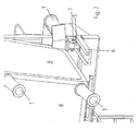
- the Fig. 2 shows the cylindrical body 1 in detail. The same applies to the connection between the carriage 5 and rail 6. In order to adjust the carriage 5, they are screwed by means of an axis 7 and a nut. The slot 11 of the rail 6 is moved to from both its Height as well as narrower of its width, so that the carriage 5 is braked in an impact in his ride by the deformation of the rails 6. All slides 5 rails 6 connections in the Fig. 1 to 6 are basically structured like the ones Fig. 2 shows.
- the Fig. 3 shows the cylindrical body 1 as damping elements to the cabin element, which is a transparent disc 8 made of plastic, which are arranged in the direction of travel of the portal stacker 2.
- the combination of four rails 6 and slide 5 in this direction allow additional damping of the cabin in this example.
- Fig. 5 shows ways that an airbag 9 cylindrical body 1 and the rail 6 and carriage 5 combination on the safety cabin 3 are advantageous to arrange.
- the Fig. 6 shows the cab 3 on the carriage 5 and rails 6 combination with a cylindrical body 1 as a deformation element to the driver's cab 3 and an airbag 12 on the viewing window of the cab 3 in front of the driver.
Landscapes
- Engineering & Computer Science (AREA)
- Mechanical Engineering (AREA)
- Warehouses Or Storage Devices (AREA)
Description
- Die Erfindung betrifft eine Sicherheitskabine für den Bediener eines Portalstaplers entsprechend dem Oberbegriff des ersten Patentanspruches.
- Die Erfindung ist überall dort anwendbar, wo an Portalstaplern Kabinen für den Bediener angeordnet sind.
- Portalstapler sind üblicherweise von einer Person gesteuert und bauen sehr hoch und schmal. Das Tragwerk von Portalstaplern besteht im Wesentlichen aus einem schmalen, hohen Portal, ist auf gummibereiften, frei lenkbaren Rädern gelagert und trägt ein Hubwerk, sodass die zu transportierenden Container auch bei erheblicher Stapelhöhe beidseitig von Stützen überfahren werden können, wobei zwischen den Stützen das geführte Lastaufnahmemittel für die Container angeordnet ist, welches den Container erfasst, anhebt und nach dem Transport an geeigneter Stelle absetzt. Die Bediener- oder Fahrerkabine ist so angeordnet, dass das Bedienpersonal den Hubvorgang gut steuern und überwachen kann, was zur Folge hat, dass die Kabine bis zu 12 m über dem Boden angeordnet ist. Um in die Kabine zu, gelangen, sind unterschiedliche Möglichkeiten bekannt.
- Zu den Möglichkeiten, die Kabine zu erreichen, gehören Leitern, Aufstiege an den Stützen oder Kabinen, die entlang der Stützen verfahrbar sind, wie das in
DE 203 20 967.1 beschrieben ist. - Die
DE 102 39 724 A1 offenbart eine Fahrerkabine, die auf Schwingungsdämpfern gelagert ist. Weiterhin ist eine Fahrerschutzstruktur vorgesehen, mittels der Stoßbelastungen auf die Fahrerkabine an die Schwingungsdämpfer übertragen werden. - Aus der
DE 23 40 776 A1 ist eine aufblasbare Schutzhülle bekannt, die den Kranbediener vor Verletzungen schützen soll. - Aus der
WO 2008/135 284 A1 ist eine Fahrerkabine mit einer erhöhten Steifigkeit bezüglich eines seitlichen Kraftangriffes bekannt. - Die
JP 2004/183 349 A - Portalstapler sind Fahrzeuge, die geeignet sind, mit oder ohne Last in hohem Tempo zu verfahren, zu beschleunigen und zu bremsen. Trotz elektrischer Bediener/Assistenz-Systeme sind die Maschinen kippgefährdet, wobei das Kippen zum einen aufgrund unangemessener Geschwindigkeit, Beschleunigung oder durch in Häfen nicht selten vorkommende Witterungsbedingungen bedingt ist.
- Die Gefahr des Kippens kann mit Hilfe elektronischer Steuerungen eingeschränkt, jedoch nicht vermieden werden.
- Kabinen von Portalstaplern weisen nicht nur die Eigenart auf, dass diese sehr hoch am Fahrzeug angeordnet sind, sondern auch, dass diese möglichst ein gutes Sichtfeld auf die darunter liegende Arbeitsfläche haben. Deshalb sind in der Regel in der Kabine von oben bis unten reichende Sichtfenster in alle Richtungen angeordnet. Kabinen für den Bediener eines Portalstaplers können in unterschiedlichen Höhen am Portalstapler angeordnet sein. Daher unterscheiden sich die Anforderungen an die Kabinen von Kabinen, die an ähnlichen Fahrzeugen vorhanden sind.
- Aufgabe der Erfindung ist es daher, eine Kabine zu entwickeln, welche im Falle eines Umkippens oder einer Kollision des Portalstaplers bei Aufprall der Kabine auf den Boden oder ein anderes Hindernis aus großer Höhe gewährleistet, dass die Wirkung des Aufpralls auf den Bediener deutlich gemindert wird.
- Diese Aufgabe wird durch eine Sicherheitskabine nach den Merkmalen des ersten Patentanspruches gelöst.
- Unteransprüche geben vorteilhafte Ausgestaltungen der Erfindung wieder.
- Die erfindungsgemäße Lösung sieht eine Sicherheitskabine für den Bediener eines Portalstaplers vor, an der Knautschzonen in Form von Deformationselementen oder Dämpfungselemente angeordnet sind, welche an geeigneter Stelle der Außenseite der Kabine dafür sorgen, dass im Falle eines Aufpralls die Verformung des Deformationselementes oder des Dämpfungselementes erfolgt oder aber die auftretenden Kräfte von diesen aufgenommen werden, wobei bei Aufprall eine Verformung erfolgt. Durch die Deformation des Deformationselementes wird kinematische Energie in Verformungsenergie umgewandelt. Der Aufprall wird dadurch gedämpft. Die Deformationselemente werden daher auch als Dämpfungselemente bezeichnet. Damit bleibt die Verzögerung auf ein für den Bediener erträgliches Maß beschränkt. Die Verformung kann reversibel oder irreversibel sein. Des Weiteren sieht die Lösung vor, dass in der Kabine an geeigneter Stelle eine oder mehrere Airbag-Systeme bekannten Prinzips installiert werden, welche den sich in Richtung der Aufprallfläche bewegenden Körper des Bedieners von einem Aufprall von Teilen in oder an der Kabine schützen und somit Verletzungen vermeiden.
- An der Kabine können Deformationselemente angeordnet sein. Dabei kann es sich zum einen um zylindrische Körper an einer geeigneten Stelle an der Außenseite der Kabine, z. B. an jeder Ecke der zu schützenden Fläche handeln, die bei einem Aufprall deformiert werden. Diese Deformationskörper können aus Metall oder aus Gummi oder einem anderen Werkstoff bestehen, welcher mittels plastischer oder elastischer Verformung Energie aufnimmt. Es kann sich in vorteilhafter Weise auch um Hydraulikzylinder oder Federn handeln. Alle Deformationselemente müssen immer so ausgelegt sein, dass dem Aufprall der Kabine eines Portalstaplers mit Container entsprechende Deformationskräfte entgegengesetzt werden.
- Als Deformationselemente sind auch flächige Körper anordenbar, beispielsweise durchsichtige Formkörper, die aus Duroplast bestehen und durch ihre Verformung oder ihre Zerstörung auftretende Kräfte aufnehmen. Selbstverständlich ist auch eine Kombination unterschiedlicher Deformationselemente untereinander möglich, das heißt, flächige durchsichtige Formkörper aus Duroplast können problemlos mit Deformationselementen aus Gummi oder aus Stahlblech kombiniert werden.
- Weiterhin ist es vorteilhaft, Airbags innerhalb oder außerhalb der Sicherheitskabine anzuordnen. Beispielsweise kann in vorteilhafter Weise ein Airbag im Lenkrad angeordnet sein. Ein rolloartiger Airbag ist vorteilhaft über den Sichtfenstern in der Richtung anzuordnen, in die ein Umkippen oder ein Zusammenprall möglich ist.
- Eine andere Möglichkeit, die auftretenden Kräfte für die Sicherheitskabine im Fall eines Aufpralls oder eines Umkippens zu senken, besteht darin, die Kabine an oder auf einer Schiene mit einem Schlitten anzuordnen und zu fixieren. Die Schienen sind dann in vorteilhafter Weise so auszubilden, dass sie einen sich verengenden Schlitz aufweisen, in den die Kabine mit dem Schlitten hineinfährt. Die Kabine kann auf diesen Vorrichtungen stehend mit einem Gelenk gelagert werden oder aber auch hängend oder stehend und hängend, wobei es weiterhin vorteilhaft ist, wenn die Schienen, die oben und unten angeordnet sind, in Richtung auf ihre Enden einen geringeren Abstand zueinander aufweisen, sodass auch durch diese Anordnung erreicht wird, dass die Bewegung der Kabine in Richtung auf das Ende der Schiene stark verzögert wird, ggf. eine Verformung der Schiene und der gesamten Kabine auftritt, sodass der Aufprall des Bedieners verzögert wird.
- Die Lösung hat den Vorteil, dass bei Umkippen oder Kollision des Portalstaplers beim Aufprall der Kabine auf ein Hindernis die Wirkung des Aufpralls auf den Bediener stark gemildert wird.
- Im Weiteren wird die Erfindung an einem Ausführungsbeispiel und sechs Figuren erläutert. Die Figuren zeigen:
- Fig. 1:
- Sicherheitskabine an einem Portalstapler mit beidseitig ange- ordneten Deformationselementen und Schlit- ten/Schienenlagerung oberhalb und unterhalb der Kabine;
- Fig. 2:
- Detaildarstellung von zwei Dämpfungselementen bzw. Defor- mationselementen und der Schienen/Schlittenverbindung der Si- cherheitskabine;
- Fig. 3:
- In Fahrtrichtung angeordnete Schienen/Schlittenverbindung und Fahrerkabine mit zwei Dämpfungselementen bzw. Deformati- onselementen in Detaildarstellung;
- Fig. 4:
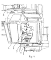
- Sicherheitskabine an einem Portalstapler mit Deformationsele- ment, welches als flächiger Formkörper ausgebildet ist;
- Fig. 5:
- Sicherheitskabine und darin und außen angeordnete Airbags;
- Fig. 6:
- Sicherheitskabine mit außen angeordnetem Airbag.
- Die
Fig. 1 zeigt einen Portalstapler 2, an dem die Sicherheitskabine 3 angeordnet ist, wobei die Kabinenelemente 8, die den Bediener umgeben, durchsichtig sind. Deformationselemente stellen an der gezeigten Sicherheitskabine 3 zylindrische Körper 1 dar, die an jeder Ecke um das Kabinenelement 8 angeordnet sind und im vorliegenden Fall einen Aufprall nach rechts oder nach links dämpfen. Die Sicherheitskabine 3 ist mit Schlitten 5 auf Schienen 6 angeordnet. Es sind jeweils zwei Schienen 6 oben und unten angeordnet. Die Schienen 6 weisen eine leichte Neigung zueinander auf, d. h. der Abstand 10 der Schienen 6 wird nach vom geringer, sodass beim Bewegen der Schlitten 5 entlang der Schiene 6 Zwangskräfte entstehen, die zu einer Deformation der Schienen 6 führen, sodass eine Bewegung der Kabine 3 aus ihrer gezeigten Lage heraus zu einer Deformation der Schienen 6 führt. Die zylindrischen Körper 1 sind so aufgebaut, dass bei einem Umkippen des Portalstaplers 2 durch die auftretenden Kräfte eine Deformation erfolgt, sodass der Aufschlag der Sicherheitskabine 3 gebremst wird. - Die
Fig. 2 zeigt den zylindrischen Körper 1 im Detail. Gleiches gilt für die Verbindung zwischen Schlitten 5 und Schiene 6. Um die Schlitten 5 einstellen zu können, sind diese mittels einer Achse 7 und einer Mutter verschraubt. Der Schlitz 11 der Schiene 6 wird nach vom sowohl von seiner Höhe als auch von seiner Breite enger, sodass der Schlitten 5 bei einem Aufprall in seiner Fahrt durch die Verformung der Schienen 6 gebremst wird. Alle Schlitten 5 Schienen 6 Verbindungen in denFig. 1 bis 6 sind grundsätzlich so aufgebaut wie das dieFig. 2 zeigt. - Die
Fig. 3 zeigt die zylindrischen Körper 1 als Dämpfungselemente um das Kabinenelement, welche eine durchsichtige Scheibe 8 aus Kunststoff darstellt, die in Fahrtrichtung des Portalstaplers 2 angeordnet sind. Die Kombination aus vier Schienen 6 und Schlitten 5 in diese Richtung ermöglichen auch in diesem Beispiel eine zusätzliche Dämpfung der Kabine. - Eine Sicherheitskabine 3, deren Deformationselemente als Formelement 4 um das Sichtfenster in Fahrtrichtung ausgeführt ist, ist der
Fig. 4 zu entnehmen. Weiterhin ist ein Airbag 9 auf dem Lenkrad des Bedieners angeordnet. Die Kabine 3 ist ebenfalls durch eine Kombination von Schienen 6 und Schlitten 5 in Fahrtrichtung gesichert. Weiterhin ist ein rolloartiger Airbag 12 auf dem Sichtfenster in Fahrtrichtung angeordnet. -
Fig. 5 zeigt Möglichkeiten, ein Airbag 9 zylindrische Körper 1 und die Schiene 6 und Schlitten 5 Kombination an der Sicherheitskabine 3 vorteilhaft anzuordnen sind. - Die
Fig. 6 zeigt die Fahrerkabine 3 an der Schlitten 5 und Schienen 6 Kombination mit zylindrischem Körper 1 als Deformationselement um die Fahrerkabine 3 und einen Airbag 12 am Sichtfenster der Fahrerkabine 3 vor dem Fahrzeugführer.
Claims (12)
- Sicherheitskabine für den Bediener eines Portalstaplers zum Transportieren und Stapeln von Containern dadurch gekennzeichnet, dass an der Kabine (3) ein Deformationselement (1, 4) angeordnet ist.
- Sicherheitskabine nach Anspruch 1, dadurch gekennzeichnet, dass die Deformationselemente zylindrische Körper (1) an der zu schützenden Fläche darstellen.
- Sicherheitskabine nach Anspruch 1, dadurch gekennzeichnet, dass die Deformationselemente Formkörper um das Sichtfenster darstellen.
- Sicherheitskabine nach Anspruch 3, dadurch gekennzeichnet, dass die flächigen Formkörper durchsichtige Formkörper aus Duroplast darstellen.
- Sicherheitskabine nach den Ansprüchen 1 bis 4, dadurch gekennzeichnet, dass die Deformationselemente Hydraulikzylinder oder Federn darstellen.
- Sicherheitskabine nach den Ansprüchen 1 bis 5, dadurch gekennzeichnet, dass die Deformationselemente ausknickende Gummielemente darstellen.
- Sicherheitskabine nach Anspruch 1, dadurch gekennzeichnet, dass die Deformationselemente eine Schienen (6) Schlitten (5)-Verbindung zwischen Kabine (3) und dem Portalstapler (2) darstellen, wobei Schiene (6) und Schlitten (5) geeignet sind, bei einem Aufprall gegeneinander so zu verfahren, dass der Aufprall gebremst wird.
- Sicherheitskabine nach Anspruch 7, dadurch gekennzeichnet, dass die Schienen (6) in Richtung auf ihre Enden einen sich verjüngenden Schlitz (11) aufweisen.
- Sicherheitskabine nach den Ansprüchen 7 und 8, dadurch gekennzeichnet, dass die Schienen (6) in Richtung auf ihre Enden so angeordnet sind, dass sich der Abstand (10) zur jeweils anderen Schiene (6) verringert, sodass ein Moment in Richtung auf die jeweils andere Schiene (6) auftritt.
- Sicherheitskabine nach den Ansprüchen 7 bis 9, dadurch gekennzeichnet, dass die Schienen- und Schlitten-(6, 5)verbindung oben und unten in Aufprallrichtung der Kabine (3) angeordnet sind.
- Sicherheitskabine nach den Ansprüchen 1 bis 10, dadurch gekennzeichnet, dass ein Airbag (9) im Lenkrad angeordnet ist.
- Sicherheitskabine nach den Ansprüchen 1 bis 11, dadurch gekennzeichnet, dass rolloartige Airbags (12) über den Kabinenscheiben (8) angeordnet sind.
Applications Claiming Priority (1)
| Application Number | Priority Date | Filing Date | Title |
|---|---|---|---|
| DE200910057477 DE102009057477A1 (de) | 2009-12-10 | 2009-12-10 | Sicherheitskabine für den Bediener eines Portalstaplers |
Publications (2)
| Publication Number | Publication Date |
|---|---|
| EP2332878A1 EP2332878A1 (de) | 2011-06-15 |
| EP2332878B1 true EP2332878B1 (de) | 2012-06-20 |
Family
ID=43626949
Family Applications (1)
| Application Number | Title | Priority Date | Filing Date |
|---|---|---|---|
| EP20100192733 Not-in-force EP2332878B1 (de) | 2009-12-10 | 2010-11-26 | Sicherheitskabine für den Bediener eines Portalstaplers |
Country Status (2)
| Country | Link |
|---|---|
| EP (1) | EP2332878B1 (de) |
| DE (1) | DE102009057477A1 (de) |
Families Citing this family (2)
| Publication number | Priority date | Publication date | Assignee | Title |
|---|---|---|---|---|
| CN111152854A (zh) * | 2020-02-06 | 2020-05-15 | 崔洁 | 一种机械工程驾驶舱防护装置 |
| CN114835058B (zh) * | 2022-06-02 | 2024-02-20 | 浙江工业大学台州研究院 | 一种避免货物运输过程中视野受阻风险的小型电动叉车 |
Family Cites Families (7)
| Publication number | Priority date | Publication date | Assignee | Title |
|---|---|---|---|---|
| DE2340776A1 (de) * | 1973-08-11 | 1975-02-27 | Mayer Peter | Sicherheitszelle |
| NL1016045C1 (nl) * | 2000-08-29 | 2002-03-01 | Christiaan Johan Jansen | Verbeterde uitvoering en plaatsing van anti-beklemmingsinrichting op vorkheftrucks of knikladers. |
| KR100464734B1 (ko) * | 2001-12-18 | 2005-01-05 | 볼보 컨스트럭션 이키프먼트 홀딩 스웨덴 에이비 | 운전실에 설치되는 운전자 보호구조물 하중 지지장치 |
| JP2004183349A (ja) * | 2002-12-04 | 2004-07-02 | Takahashiworks Co Ltd | エアバッグ付キャビン上部張出保護装置 |
| DE20320967U1 (de) | 2003-10-27 | 2005-07-28 | Noell Mobile Systems & Cranes Gmbh | Arbeitsbühne zur Beförderung von Personen |
| SE526130C2 (sv) * | 2003-11-10 | 2005-07-12 | Volvo Constr Equip Holding Se | Hyttstöd |
| DE202007006500U1 (de) * | 2007-05-07 | 2008-09-18 | Liebherr-Hydraulikbagger Gmbh | Baumaschine |
-
2009
- 2009-12-10 DE DE200910057477 patent/DE102009057477A1/de not_active Withdrawn
-
2010
- 2010-11-26 EP EP20100192733 patent/EP2332878B1/de not_active Not-in-force
Also Published As
| Publication number | Publication date |
|---|---|
| DE102009057477A1 (de) | 2011-06-16 |
| EP2332878A1 (de) | 2011-06-15 |
Similar Documents
| Publication | Publication Date | Title |
|---|---|---|
| EP3319901B1 (de) | Hubvorrichtung | |
| EP0458184B2 (de) | Gabelstapler | |
| EP3263510B1 (de) | Abstützvorrichtung mit einrichtung zur reduzierung von schwingungen | |
| DE102014100865B4 (de) | Routenzuganhänger mit einem Fahrgestell und einer Transportvorrichtung | |
| DE1924223A1 (de) | Seitenlader | |
| DE102016207526A1 (de) | Flurförderzeug mit einer Einrichtung zur Reduzierung von Schwingungen | |
| EP3255012B1 (de) | Flurförderzeug mit einer einrichtung zur reduzierung von schwingungen | |
| EP3447023B1 (de) | Autonomes flurförderzeug, insbesondere kommissionier-flurförderzeug | |
| EP3433202B1 (de) | Fahrzeug mit seitlicher hubeinrichtung | |
| EP0733003B1 (de) | Fahrzeug mit einem aufbau | |
| EP2103506B1 (de) | Flurförderzeug | |
| WO2009086904A1 (de) | Rahmenkopf für einen fahrzeugrahmen eines lastkraftwagens | |
| DE60013632T2 (de) | Fahrzeug, insbesondere pkw, mit kastenstruktur gegen aufklettern beim aufprall | |
| EP3472029B1 (de) | Fahrgestellanordnung und landfahrzeug | |
| EP2332878A1 (de) | Sicherheitskabine für den Bediener eines Portalstaplers | |
| EP2480477B1 (de) | Portalhubwagen zum einsatz in containerterminals und für allgemeine transportaufgaben | |
| DE102004061707A1 (de) | Fahrzeugkarosserie | |
| EP2256749A1 (de) | Stoßdämpfungsvorrichtung für Transport-/Lagerbehälter von radioaktivem Material | |
| AT509458B1 (de) | Regallager mit regalbediengerät | |
| DE102022113795A1 (de) | Shuttle für ein Regalsystem | |
| DE10360298A1 (de) | Gefederte Fahrerplattform | |
| DE102017117492B4 (de) | Hubfahrzeug zum Transport von Personen im Flughafenbereich | |
| DE102015012538B4 (de) | Radaufhängung | |
| EP0758597A2 (de) | Sicherheitsstossstange für Personenkraftwagen | |
| DE10121617B4 (de) | Vorfeld-Fahrzeug |
Legal Events
| Date | Code | Title | Description |
|---|---|---|---|
| PUAI | Public reference made under article 153(3) epc to a published international application that has entered the european phase |
Free format text: ORIGINAL CODE: 0009012 |
|
| AK | Designated contracting states |
Kind code of ref document: A1 Designated state(s): AL AT BE BG CH CY CZ DE DK EE ES FI FR GB GR HR HU IE IS IT LI LT LU LV MC MK MT NL NO PL PT RO RS SE SI SK SM TR |
|
| AX | Request for extension of the european patent |
Extension state: BA ME |
|
| 17P | Request for examination filed |
Effective date: 20111122 |
|
| GRAP | Despatch of communication of intention to grant a patent |
Free format text: ORIGINAL CODE: EPIDOSNIGR1 |
|
| RIC1 | Information provided on ipc code assigned before grant |
Ipc: B60R 21/13 20060101ALI20111212BHEP Ipc: B66F 17/00 20060101ALI20111212BHEP Ipc: B66C 19/00 20060101ALI20111212BHEP Ipc: B66C 13/54 20060101AFI20111212BHEP Ipc: B62D 33/06 20060101ALI20111212BHEP Ipc: B60R 21/203 20060101ALI20111212BHEP |
|
| GRAS | Grant fee paid |
Free format text: ORIGINAL CODE: EPIDOSNIGR3 |
|
| GRAA | (expected) grant |
Free format text: ORIGINAL CODE: 0009210 |
|
| AK | Designated contracting states |
Kind code of ref document: B1 Designated state(s): AL AT BE BG CH CY CZ DE DK EE ES FI FR GB GR HR HU IE IS IT LI LT LU LV MC MK MT NL NO PL PT RO RS SE SI SK SM TR |
|
| REG | Reference to a national code |
Ref country code: GB Ref legal event code: FG4D Free format text: NOT ENGLISH |
|
| REG | Reference to a national code |
Ref country code: CH Ref legal event code: EP |
|
| REG | Reference to a national code |
Ref country code: AT Ref legal event code: REF Ref document number: 562973 Country of ref document: AT Kind code of ref document: T Effective date: 20120715 |
|
| REG | Reference to a national code |
Ref country code: IE Ref legal event code: FG4D Free format text: LANGUAGE OF EP DOCUMENT: GERMAN |
|
| REG | Reference to a national code |
Ref country code: DE Ref legal event code: R096 Ref document number: 502010000912 Country of ref document: DE Effective date: 20120816 |
|
| PG25 | Lapsed in a contracting state [announced via postgrant information from national office to epo] |
Ref country code: LT Free format text: LAPSE BECAUSE OF FAILURE TO SUBMIT A TRANSLATION OF THE DESCRIPTION OR TO PAY THE FEE WITHIN THE PRESCRIBED TIME-LIMIT Effective date: 20120620 Ref country code: SE Free format text: LAPSE BECAUSE OF FAILURE TO SUBMIT A TRANSLATION OF THE DESCRIPTION OR TO PAY THE FEE WITHIN THE PRESCRIBED TIME-LIMIT Effective date: 20120620 Ref country code: RS Free format text: LAPSE BECAUSE OF FAILURE TO SUBMIT A TRANSLATION OF THE DESCRIPTION OR TO PAY THE FEE WITHIN THE PRESCRIBED TIME-LIMIT Effective date: 20120620 Ref country code: NO Free format text: LAPSE BECAUSE OF FAILURE TO SUBMIT A TRANSLATION OF THE DESCRIPTION OR TO PAY THE FEE WITHIN THE PRESCRIBED TIME-LIMIT Effective date: 20120920 |
|
| REG | Reference to a national code |
Ref country code: NL Ref legal event code: VDEP Effective date: 20120620 |
|
| REG | Reference to a national code |
Ref country code: LT Ref legal event code: MG4D Effective date: 20120620 |
|
| PG25 | Lapsed in a contracting state [announced via postgrant information from national office to epo] |
Ref country code: SI Free format text: LAPSE BECAUSE OF FAILURE TO SUBMIT A TRANSLATION OF THE DESCRIPTION OR TO PAY THE FEE WITHIN THE PRESCRIBED TIME-LIMIT Effective date: 20120620 Ref country code: GR Free format text: LAPSE BECAUSE OF FAILURE TO SUBMIT A TRANSLATION OF THE DESCRIPTION OR TO PAY THE FEE WITHIN THE PRESCRIBED TIME-LIMIT Effective date: 20120921 Ref country code: HR Free format text: LAPSE BECAUSE OF FAILURE TO SUBMIT A TRANSLATION OF THE DESCRIPTION OR TO PAY THE FEE WITHIN THE PRESCRIBED TIME-LIMIT Effective date: 20120620 Ref country code: LV Free format text: LAPSE BECAUSE OF FAILURE TO SUBMIT A TRANSLATION OF THE DESCRIPTION OR TO PAY THE FEE WITHIN THE PRESCRIBED TIME-LIMIT Effective date: 20120620 |
|
| PG25 | Lapsed in a contracting state [announced via postgrant information from national office to epo] |
Ref country code: CY Free format text: LAPSE BECAUSE OF FAILURE TO SUBMIT A TRANSLATION OF THE DESCRIPTION OR TO PAY THE FEE WITHIN THE PRESCRIBED TIME-LIMIT Effective date: 20120620 Ref country code: IS Free format text: LAPSE BECAUSE OF FAILURE TO SUBMIT A TRANSLATION OF THE DESCRIPTION OR TO PAY THE FEE WITHIN THE PRESCRIBED TIME-LIMIT Effective date: 20121020 Ref country code: RO Free format text: LAPSE BECAUSE OF FAILURE TO SUBMIT A TRANSLATION OF THE DESCRIPTION OR TO PAY THE FEE WITHIN THE PRESCRIBED TIME-LIMIT Effective date: 20120620 Ref country code: SK Free format text: LAPSE BECAUSE OF FAILURE TO SUBMIT A TRANSLATION OF THE DESCRIPTION OR TO PAY THE FEE WITHIN THE PRESCRIBED TIME-LIMIT Effective date: 20120620 Ref country code: CZ Free format text: LAPSE BECAUSE OF FAILURE TO SUBMIT A TRANSLATION OF THE DESCRIPTION OR TO PAY THE FEE WITHIN THE PRESCRIBED TIME-LIMIT Effective date: 20120620 Ref country code: EE Free format text: LAPSE BECAUSE OF FAILURE TO SUBMIT A TRANSLATION OF THE DESCRIPTION OR TO PAY THE FEE WITHIN THE PRESCRIBED TIME-LIMIT Effective date: 20120620 |
|
| PG25 | Lapsed in a contracting state [announced via postgrant information from national office to epo] |
Ref country code: PL Free format text: LAPSE BECAUSE OF FAILURE TO SUBMIT A TRANSLATION OF THE DESCRIPTION OR TO PAY THE FEE WITHIN THE PRESCRIBED TIME-LIMIT Effective date: 20120620 Ref country code: PT Free format text: LAPSE BECAUSE OF FAILURE TO SUBMIT A TRANSLATION OF THE DESCRIPTION OR TO PAY THE FEE WITHIN THE PRESCRIBED TIME-LIMIT Effective date: 20121022 |
|
| PG25 | Lapsed in a contracting state [announced via postgrant information from national office to epo] |
Ref country code: NL Free format text: LAPSE BECAUSE OF FAILURE TO SUBMIT A TRANSLATION OF THE DESCRIPTION OR TO PAY THE FEE WITHIN THE PRESCRIBED TIME-LIMIT Effective date: 20120620 |
|
| PLBE | No opposition filed within time limit |
Free format text: ORIGINAL CODE: 0009261 |
|
| STAA | Information on the status of an ep patent application or granted ep patent |
Free format text: STATUS: NO OPPOSITION FILED WITHIN TIME LIMIT |
|
| PG25 | Lapsed in a contracting state [announced via postgrant information from national office to epo] |
Ref country code: DK Free format text: LAPSE BECAUSE OF FAILURE TO SUBMIT A TRANSLATION OF THE DESCRIPTION OR TO PAY THE FEE WITHIN THE PRESCRIBED TIME-LIMIT Effective date: 20120620 Ref country code: ES Free format text: LAPSE BECAUSE OF FAILURE TO SUBMIT A TRANSLATION OF THE DESCRIPTION OR TO PAY THE FEE WITHIN THE PRESCRIBED TIME-LIMIT Effective date: 20121001 |
|
| 26N | No opposition filed |
Effective date: 20130321 |
|
| BERE | Be: lapsed |
Owner name: NOELL MOBILE SYSTEMS G.M.B.H. Effective date: 20121130 |
|
| REG | Reference to a national code |
Ref country code: DE Ref legal event code: R097 Ref document number: 502010000912 Country of ref document: DE Effective date: 20130321 |
|
| PG25 | Lapsed in a contracting state [announced via postgrant information from national office to epo] |
Ref country code: BG Free format text: LAPSE BECAUSE OF FAILURE TO SUBMIT A TRANSLATION OF THE DESCRIPTION OR TO PAY THE FEE WITHIN THE PRESCRIBED TIME-LIMIT Effective date: 20120920 |
|
| REG | Reference to a national code |
Ref country code: FR Ref legal event code: ST Effective date: 20130731 |
|
| PG25 | Lapsed in a contracting state [announced via postgrant information from national office to epo] |
Ref country code: BE Free format text: LAPSE BECAUSE OF NON-PAYMENT OF DUE FEES Effective date: 20121130 |
|
| PG25 | Lapsed in a contracting state [announced via postgrant information from national office to epo] |
Ref country code: MT Free format text: LAPSE BECAUSE OF FAILURE TO SUBMIT A TRANSLATION OF THE DESCRIPTION OR TO PAY THE FEE WITHIN THE PRESCRIBED TIME-LIMIT Effective date: 20120620 Ref country code: FR Free format text: LAPSE BECAUSE OF NON-PAYMENT OF DUE FEES Effective date: 20121130 Ref country code: AL Free format text: LAPSE BECAUSE OF FAILURE TO SUBMIT A TRANSLATION OF THE DESCRIPTION OR TO PAY THE FEE WITHIN THE PRESCRIBED TIME-LIMIT Effective date: 20120620 |
|
| PG25 | Lapsed in a contracting state [announced via postgrant information from national office to epo] |
Ref country code: MC Free format text: LAPSE BECAUSE OF NON-PAYMENT OF DUE FEES Effective date: 20121130 Ref country code: TR Free format text: LAPSE BECAUSE OF FAILURE TO SUBMIT A TRANSLATION OF THE DESCRIPTION OR TO PAY THE FEE WITHIN THE PRESCRIBED TIME-LIMIT Effective date: 20120620 |
|
| PG25 | Lapsed in a contracting state [announced via postgrant information from national office to epo] |
Ref country code: LU Free format text: LAPSE BECAUSE OF NON-PAYMENT OF DUE FEES Effective date: 20121126 Ref country code: SM Free format text: LAPSE BECAUSE OF FAILURE TO SUBMIT A TRANSLATION OF THE DESCRIPTION OR TO PAY THE FEE WITHIN THE PRESCRIBED TIME-LIMIT Effective date: 20120620 |
|
| PG25 | Lapsed in a contracting state [announced via postgrant information from national office to epo] |
Ref country code: HU Free format text: LAPSE BECAUSE OF FAILURE TO SUBMIT A TRANSLATION OF THE DESCRIPTION OR TO PAY THE FEE WITHIN THE PRESCRIBED TIME-LIMIT Effective date: 20101126 |
|
| REG | Reference to a national code |
Ref country code: CH Ref legal event code: PL |
|
| GBPC | Gb: european patent ceased through non-payment of renewal fee |
Effective date: 20141126 |
|
| PG25 | Lapsed in a contracting state [announced via postgrant information from national office to epo] |
Ref country code: LI Free format text: LAPSE BECAUSE OF NON-PAYMENT OF DUE FEES Effective date: 20141130 Ref country code: CH Free format text: LAPSE BECAUSE OF NON-PAYMENT OF DUE FEES Effective date: 20141130 Ref country code: MK Free format text: LAPSE BECAUSE OF FAILURE TO SUBMIT A TRANSLATION OF THE DESCRIPTION OR TO PAY THE FEE WITHIN THE PRESCRIBED TIME-LIMIT Effective date: 20120620 |
|
| PG25 | Lapsed in a contracting state [announced via postgrant information from national office to epo] |
Ref country code: GB Free format text: LAPSE BECAUSE OF NON-PAYMENT OF DUE FEES Effective date: 20141126 |
|
| REG | Reference to a national code |
Ref country code: DE Ref legal event code: R082 Ref document number: 502010000912 Country of ref document: DE Representative=s name: MOSER GOETZE & PARTNER PATENTANWAELTE MBB, DE |
|
| REG | Reference to a national code |
Ref country code: DE Ref legal event code: R081 Ref document number: 502010000912 Country of ref document: DE Owner name: KONECRANES GLOBAL CORP., FI Free format text: FORMER OWNER: NOELL MOBILE SYSTEMS GMBH, 97080 WUERZBURG, DE Ref country code: DE Ref legal event code: R082 Ref document number: 502010000912 Country of ref document: DE Representative=s name: MOSER GOETZE & PARTNER PATENTANWAELTE MBB, DE Ref country code: DE Ref legal event code: R081 Ref document number: 502010000912 Country of ref document: DE Owner name: TEREX MHPS IP MANAGEMENT GMBH, DE Free format text: FORMER OWNER: NOELL MOBILE SYSTEMS GMBH, 97080 WUERZBURG, DE Ref country code: DE Ref legal event code: R081 Ref document number: 502010000912 Country of ref document: DE Owner name: KONECRANES GLOBAL CORPORATION, FI Free format text: FORMER OWNER: NOELL MOBILE SYSTEMS GMBH, 97080 WUERZBURG, DE |
|
| REG | Reference to a national code |
Ref country code: AT Ref legal event code: MM01 Ref document number: 562973 Country of ref document: AT Kind code of ref document: T Effective date: 20151126 |
|
| PG25 | Lapsed in a contracting state [announced via postgrant information from national office to epo] |
Ref country code: AT Free format text: LAPSE BECAUSE OF NON-PAYMENT OF DUE FEES Effective date: 20151126 |
|
| REG | Reference to a national code |
Ref country code: DE Ref legal event code: R081 Ref document number: 502010000912 Country of ref document: DE Owner name: KONECRANES GLOBAL CORP., FI Free format text: FORMER OWNER: TEREX MHPS IP MANAGEMENT GMBH, 40597 DUESSELDORF, DE Ref country code: DE Ref legal event code: R082 Ref document number: 502010000912 Country of ref document: DE Representative=s name: MOSER GOETZE & PARTNER PATENTANWAELTE MBB, DE Ref country code: DE Ref legal event code: R081 Ref document number: 502010000912 Country of ref document: DE Owner name: KONECRANES GLOBAL CORPORATION, FI Free format text: FORMER OWNER: TEREX MHPS IP MANAGEMENT GMBH, 40597 DUESSELDORF, DE |
|
| PGFP | Annual fee paid to national office [announced via postgrant information from national office to epo] |
Ref country code: FI Payment date: 20191121 Year of fee payment: 10 Ref country code: IE Payment date: 20191121 Year of fee payment: 10 Ref country code: DE Payment date: 20191121 Year of fee payment: 10 |
|
| PGFP | Annual fee paid to national office [announced via postgrant information from national office to epo] |
Ref country code: IT Payment date: 20191128 Year of fee payment: 10 |
|
| REG | Reference to a national code |
Ref country code: DE Ref legal event code: R119 Ref document number: 502010000912 Country of ref document: DE |
|
| REG | Reference to a national code |
Ref country code: FI Ref legal event code: MAE |
|
| PG25 | Lapsed in a contracting state [announced via postgrant information from national office to epo] |
Ref country code: FI Free format text: LAPSE BECAUSE OF NON-PAYMENT OF DUE FEES Effective date: 20201126 |
|
| PG25 | Lapsed in a contracting state [announced via postgrant information from national office to epo] |
Ref country code: IE Free format text: LAPSE BECAUSE OF NON-PAYMENT OF DUE FEES Effective date: 20201126 Ref country code: IT Free format text: LAPSE BECAUSE OF NON-PAYMENT OF DUE FEES Effective date: 20201126 |
|
| PG25 | Lapsed in a contracting state [announced via postgrant information from national office to epo] |
Ref country code: DE Free format text: LAPSE BECAUSE OF NON-PAYMENT OF DUE FEES Effective date: 20210601 |