EP2332710A1 - Venting device for a mold - Google Patents
Venting device for a mold Download PDFInfo
- Publication number
- EP2332710A1 EP2332710A1 EP10194552A EP10194552A EP2332710A1 EP 2332710 A1 EP2332710 A1 EP 2332710A1 EP 10194552 A EP10194552 A EP 10194552A EP 10194552 A EP10194552 A EP 10194552A EP 2332710 A1 EP2332710 A1 EP 2332710A1
- Authority
- EP
- European Patent Office
- Prior art keywords
- blocking member
- mold
- previous
- mold blocking
- cap
- Prior art date
- Legal status (The legal status is an assumption and is not a legal conclusion. Google has not performed a legal analysis and makes no representation as to the accuracy of the status listed.)
- Granted
Links
Images
Classifications
-
- B—PERFORMING OPERATIONS; TRANSPORTING
- B29—WORKING OF PLASTICS; WORKING OF SUBSTANCES IN A PLASTIC STATE IN GENERAL
- B29D—PRODUCING PARTICULAR ARTICLES FROM PLASTICS OR FROM SUBSTANCES IN A PLASTIC STATE
- B29D30/00—Producing pneumatic or solid tyres or parts thereof
- B29D30/06—Pneumatic tyres or parts thereof (e.g. produced by casting, moulding, compression moulding, injection moulding, centrifugal casting)
- B29D30/0601—Vulcanising tyres; Vulcanising presses for tyres
- B29D30/0606—Vulcanising moulds not integral with vulcanising presses
-
- B—PERFORMING OPERATIONS; TRANSPORTING
- B29—WORKING OF PLASTICS; WORKING OF SUBSTANCES IN A PLASTIC STATE IN GENERAL
- B29D—PRODUCING PARTICULAR ARTICLES FROM PLASTICS OR FROM SUBSTANCES IN A PLASTIC STATE
- B29D30/00—Producing pneumatic or solid tyres or parts thereof
- B29D30/06—Pneumatic tyres or parts thereof (e.g. produced by casting, moulding, compression moulding, injection moulding, centrifugal casting)
- B29D30/0601—Vulcanising tyres; Vulcanising presses for tyres
- B29D30/0606—Vulcanising moulds not integral with vulcanising presses
- B29D2030/0607—Constructional features of the moulds
- B29D2030/0617—Venting devices, e.g. vent plugs or inserts
-
- Y—GENERAL TAGGING OF NEW TECHNOLOGICAL DEVELOPMENTS; GENERAL TAGGING OF CROSS-SECTIONAL TECHNOLOGIES SPANNING OVER SEVERAL SECTIONS OF THE IPC; TECHNICAL SUBJECTS COVERED BY FORMER USPC CROSS-REFERENCE ART COLLECTIONS [XRACs] AND DIGESTS
- Y10—TECHNICAL SUBJECTS COVERED BY FORMER USPC
- Y10S—TECHNICAL SUBJECTS COVERED BY FORMER USPC CROSS-REFERENCE ART COLLECTIONS [XRACs] AND DIGESTS
- Y10S425/00—Plastic article or earthenware shaping or treating: apparatus
- Y10S425/812—Venting
Definitions
- the invention relates to a blocking member for use in a vent bore in a mold usable for the manufacture of rubber products such as tires. More particularly, the invention is directed to a mold blocking member and a mold which is equipped with one or more such blocking members.
- the first type is the ventless type wherein the mold gasses are vented through tiny cracks in the mold surfaces.
- the second type of mold is the vented type which comprises a plurality of venting bores in which pins or other devices are inserted to block the flow of rubber while venting the mold.
- the blocking devices allow the air and mold gasses to vent while preventing the flow of rubber. Without the blocking devices, tiny spues or rubber shoots form on the surface of the article resulting in a hedge hog or bristled appearance.
- Prior art blocking devices as described in DE 198 33 730 C2 may stop the formation of these rubber shoots, but may result in marks on the surface of the tire. Thus it is desired to have an improved blocking device which allows the gasses to be vented without the formation of rubber shoots and without marks being formed on the tires.
- the invention relates to a mold blocking member in accordance with claim 1 and to a mold comprising such a mold blocking member in accordance with claim 15.
- the invention provides in a first aspect a mold blocking member for use in a vent bore of a mold for the manufacture of rubber products.
- the mold blocking member has a tubular hollow body having a first end and a second end. The second end is preferably chamfered for easy insertion into the mold.
- the first end has a spring element positioned thereon.
- a cap is affixed to a flat portion of the spring element. The bottom surface of the cap may optionally include channels.
- FIG. 1 illustrates a blocking member 10 of the present invention.
- the blocking member 10 comprises a hollow, central body 20 having a first end 12 and a second end 16.
- the central body 20 is preferably tapered from a first end 12 to a second end 16.
- the central body 20 may further comprise optional barbs (not shown) which extend like fins from the hollow body and function to secure the blocking device in the vent bores to prevent pullout during demolding.
- the central body 20 may be formed of two halves 20A, 20B which are divided by longitudinal openings 3, 4.
- the openings provide the central body free mobility in the radial direction during insertion of the device into a mold vent bore (not shown).
- the central body may be round or slightly oval to ensure a tight fit within a bore of a mold.
- the openings 3, 4 are designed to close when the blocking device is inserted into the mold vent bores.
- the blocking member 10 is preferably formed from a thin sheet of metal stock, and may be formed from stamping or punching the metal and then bending the metal into the desired profile.
- the blocking member is formed from nickel chromium metal.
- the diameter of the blocking member is preferably in a range of from 2.0 mm to 4 mm, preferably 2.5 mm to 3 mm.
- the diameter of the tubular hollow body 20a, 20b is preferably in a range of from 1.5 to 3.5 mm, preferably 2 mm to 3 mm.
- the first end of the blocking member 10 includes a spring element 22 mounted thereon.
- the spring element has a flat inner portion 24.
- the spring element 22 further comprises one or more wavy ends 26.
- the wavy ends 26 have a flanged portion 27 for connecting to the tubular end of the first end of the blocking member 10.
- the flanged portion 27 may be welded or otherwise affixed to the tubular end of the blocking member. As shown in Figure 2 , the flat portion of the spring element extends radially outward of the tubular first end.
- the cap 30 has a larger diameter than the diameter of the body 20.
- the inner surface 31 of the cap has a flat circular portion 32 which is affixed to the flat portion 24 of the spring element.
- the inner surface of the cap may optionally include one or more channels 34 on the bottom surface to guide the gas flow from the mold device.
- the distance from the inner or bottom surface 31 of the cap 30 to the leg 26 defines a distance d which may range from 0.03 mm to 0.2 mm.
- the blocking member 10 is inserted into a bore of a mold until the lower surface of the cap touches the mold surface.
- the cap springs back after insertion due to the spring element.
- An air flow channel is created between the gap of the lower surface of the cap and the tubular end of the body.
- the trapped mold gasses must travel 90 degrees down the sidewalls 36 of the cap 30 and then bend another 90 degrees into air flow channel 38.
- the air flow channel is annular.
- the double bend of the flow path acts as a labyrinth in order to block the rubber from flowing past the cap.
Landscapes
- Engineering & Computer Science (AREA)
- Mechanical Engineering (AREA)
- Moulds For Moulding Plastics Or The Like (AREA)
Abstract
Description
- The invention relates to a blocking member for use in a vent bore in a mold usable for the manufacture of rubber products such as tires. More particularly, the invention is directed to a mold blocking member and a mold which is equipped with one or more such blocking members.
- There are generally two types of molds used in the production of rubber articles such as tires. The first type is the ventless type wherein the mold gasses are vented through tiny cracks in the mold surfaces. The second type of mold is the vented type which comprises a plurality of venting bores in which pins or other devices are inserted to block the flow of rubber while venting the mold. The blocking devices allow the air and mold gasses to vent while preventing the flow of rubber. Without the blocking devices, tiny spues or rubber shoots form on the surface of the article resulting in a hedge hog or bristled appearance. Prior art blocking devices as described in
DE 198 33 730 C2 may stop the formation of these rubber shoots, but may result in marks on the surface of the tire. Thus it is desired to have an improved blocking device which allows the gasses to be vented without the formation of rubber shoots and without marks being formed on the tires. - The invention relates to a mold blocking member in accordance with claim 1 and to a mold comprising such a mold blocking member in accordance with claim 15.
- Dependent claims refer to preferred embodiments of the invention.
- The invention provides in a first aspect a mold blocking member for use in a vent bore of a mold for the manufacture of rubber products. The mold blocking member has a tubular hollow body having a first end and a second end. The second end is preferably chamfered for easy insertion into the mold. The first end has a spring element positioned thereon. A cap is affixed to a flat portion of the spring element. The bottom surface of the cap may optionally include channels.
- The invention will be described by way of example and with reference to the accompanying drawings in which:
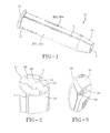
- FlG. 1 is a side view of a blocking device of the present invention;
- FlG. 2 is a partial front perspective view of the blocking device FlG. 1;
- FlG. 3 is a view of the end cap of the blocking device;
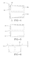
- FlG. 4 illustrates the end cap and spring element of the blocking device;
- FlG. 5 illustrates the spring element mounted on the blocking device with the end cap removed; and
- FlG. 6 illustrates the cap and upper portion of the blocking device.
-
Figure 1 illustrates a blockingmember 10 of the present invention. The blockingmember 10 comprises a hollow, central body 20 having afirst end 12 and a second end 16. The central body 20 is preferably tapered from afirst end 12 to a second end 16. The central body 20 may further comprise optional barbs (not shown) which extend like fins from the hollow body and function to secure the blocking device in the vent bores to prevent pullout during demolding. - The central body 20 may be formed of two halves 20A, 20B which are divided by longitudinal openings 3, 4. The openings provide the central body free mobility in the radial direction during insertion of the device into a mold vent bore (not shown). The central body may be round or slightly oval to ensure a tight fit within a bore of a mold. The openings 3, 4 are designed to close when the blocking device is inserted into the mold vent bores.
- The blocking
member 10 is preferably formed from a thin sheet of metal stock, and may be formed from stamping or punching the metal and then bending the metal into the desired profile. Preferably the blocking member is formed from nickel chromium metal. The diameter of the blocking member is preferably in a range of from 2.0 mm to 4 mm, preferably 2.5 mm to 3 mm. The diameter of the tubular hollow body 20a, 20b is preferably in a range of from 1.5 to 3.5 mm, preferably 2 mm to 3 mm. - The first end of the blocking
member 10 includes a spring element 22 mounted thereon. The spring element has a flatinner portion 24. The spring element 22 further comprises one or more wavy ends 26. The wavy ends 26 have a flanged portion 27 for connecting to the tubular end of the first end of the blockingmember 10. - The flanged portion 27 may be welded or otherwise affixed to the tubular end of the blocking member. As shown in
Figure 2 , the flat portion of the spring element extends radially outward of the tubular first end. - Mounted upon the flat surface of the spring element is a
cap 30. Thecap 30 has a larger diameter than the diameter of the body 20. Theinner surface 31 of the cap has a flat circular portion 32 which is affixed to theflat portion 24 of the spring element. The inner surface of the cap may optionally include one ormore channels 34 on the bottom surface to guide the gas flow from the mold device. The distance from the inner orbottom surface 31 of thecap 30 to the leg 26 defines a distance d which may range from 0.03 mm to 0.2 mm. - The blocking
member 10 is inserted into a bore of a mold until the lower surface of the cap touches the mold surface. The cap springs back after insertion due to the spring element. An air flow channel is created between the gap of the lower surface of the cap and the tubular end of the body. As shown inFigure 1 , the trapped mold gasses must travel 90 degrees down thesidewalls 36 of thecap 30 and then bend another 90 degrees intoair flow channel 38. The air flow channel is annular. The double bend of the flow path acts as a labyrinth in order to block the rubber from flowing past the cap.
Claims (15)
- A mold blocking member for use in a vent bore of a mold, the mold blocking member (10) comprising a tubular hollow body (20a, 20b) having a first end (12) and a second end (16), a spring element (22) having a flat portion (24) and one or more legs (26), wherein the legs (26) of the spring element (22) are connected to the first end (12) of the tubular hollow body (20a, 20b), the mold blocking member (10) further comprising a cap (30) having an inner surface (31) affixed to the flat portion (24) of the spring element (22)
- The mold blocking member of claim 1 wherein the flat portion (24) is of a circular or an at least substantially circular shape.
- The mold blocking member of claim 1 or 2 wherein the one or more legs (26) are wavy in cross-section and/or include a convex bending towards the tubular hollow body (20a, 20b).
- The mold blocking member of at least one of the previous claims comprising two legs (26) located on opposite sides of the flat portion (24) or a plurality of legs (26) such as three or four legs (26) located at equidistant angles around the flat portion (24).
- The mold blocking member of at least one of the previous claims wherein the one or more legs (26) each comprise a flanged portion (27), the flanged portion (27) connecting the respective leg (26) to the first end (12).
- The mold blocking member of at least one of the previous claims wherein the spring element (22) or the flanged portion (27) is welded or otherwise affixed to the first end (12), and/or wherein the cap (30) is welded or otherwise affixed to the flat portion (24).
- The mold blocking member of at least one of the previous claims wherein the spring element (22) or the flanged portion (27) is formed integrally with the tubular hollow body (20a, 20b).
- The mold blocking member of at least one of the previous claims wherein the cap (30) is of a circular or an at least substantially circular shape, and/or wherein the cap (30) is flat.
- The mold blocking member of at least one of the previous claims wherein the diameter of the cap (30) is larger, preferably 2 % to 15% or 3% to 10% larger, than the diameter of the tubular hollow body (20a, 20b).
- The mold blocking member of at least one of the previous claims wherein the cap (30) comprises one or more channels (34) or recesses on its inner surface (31) for guiding a gas flow.
- The mold blocking member of at least one of the previous claims wherein there is a distance (d) between the inner surface (31) of the cap (30) and the leg (26), the distance being at the flanged portion (27) in a range of from 0.03 mm to 0.2 mm, preferably 0.06 mm to 0.15 mm.
- The mold blocking member of at least one of the previous claims wherein there is a slot opening between the cap (30) and the first end (12) of the tubular body (20a, 20b), the slot opening having a minimum gap dimension in the range of form 0.03 mm to 0.2 mm, preferably 0.06 mm to 0.15 mm, and/or wherein the slot opening has a width dimension in the range of from 0.1 mm to 0.6 mm.
- The mold blocking member of at least one of the previous claims wherein the tubular hollow body (20a, 20b) comprises two halfes which are divided by two longitudinal openings (3, 4), and wherein the tubular hollow body (20a, 20b) is preferably tapered towards the second end (16).
- The mold blocking member of at least one of the previous claims wherein the tubular hollow body (20a, 20b) is slightly oval in cross-section, and/or wherein the longitudinal openings (3, 4) in the tubular hollow body (20a, 20b) are dimensioned such that they closed or at least substantially closed when the mold blocking member (10) is inserted into a respective mold.
- A mold for the manufacture of rubber products such as tires comprising a plurality of mold blocking members (10) in accordance with at least one of the previous claims.
Applications Claiming Priority (2)
| Application Number | Priority Date | Filing Date | Title |
|---|---|---|---|
| US28614309P | 2009-12-14 | 2009-12-14 | |
| US12/906,198 US8221106B2 (en) | 2009-12-14 | 2010-10-18 | Venting device for mold |
Publications (2)
| Publication Number | Publication Date |
|---|---|
| EP2332710A1 true EP2332710A1 (en) | 2011-06-15 |
| EP2332710B1 EP2332710B1 (en) | 2013-07-03 |
Family
ID=43742435
Family Applications (1)
| Application Number | Title | Priority Date | Filing Date |
|---|---|---|---|
| EP10194552.5A Active EP2332710B1 (en) | 2009-12-14 | 2010-12-10 | Venting device for a mold |
Country Status (2)
| Country | Link |
|---|---|
| US (1) | US8221106B2 (en) |
| EP (1) | EP2332710B1 (en) |
Families Citing this family (3)
| Publication number | Priority date | Publication date | Assignee | Title |
|---|---|---|---|---|
| JP5836731B2 (en) * | 2011-09-26 | 2015-12-24 | 東洋ゴム工業株式会社 | Tire vulcanizing mold |
| US9522509B2 (en) * | 2014-01-09 | 2016-12-20 | Bridgestone Americas Tire Operations, Llc | Tire mold vent |
| US11007735B2 (en) | 2019-08-08 | 2021-05-18 | The Goodyear Tire & Rubber Company | Tire mold |
Citations (5)
| Publication number | Priority date | Publication date | Assignee | Title |
|---|---|---|---|---|
| US5922237A (en) * | 1996-11-15 | 1999-07-13 | Dunlop Tyres Ltd. | Mold vents |
| DE19833730C2 (en) | 1998-07-27 | 2002-11-21 | Dunlop Gmbh | Tire vulcanization mold with valves installed in ventilation holes |
| EP1375105A2 (en) * | 2002-06-28 | 2004-01-02 | Ngk Insulators, Ltd. | Method and device for installing a lid into a venting hole of a tyre mould and tyre mould comprising said lid |
| WO2007139523A1 (en) * | 2006-05-25 | 2007-12-06 | Continental Matador Rubber, S.R.O. | Vent valve to be used in venting bores of vulcanization moulds |
| KR100855209B1 (en) * | 2007-06-13 | 2008-09-01 | 한국타이어 주식회사 | Venting device of tire vulcanization mold |
Family Cites Families (5)
| Publication number | Priority date | Publication date | Assignee | Title |
|---|---|---|---|---|
| US4795331A (en) * | 1986-09-15 | 1989-01-03 | The Goodyear Tire & Rubber Company | Mold vent plug |
| GB9708584D0 (en) * | 1997-04-29 | 1997-06-18 | Sp Tyres Uk Ltd | Mould vents |
| HK1039089A1 (en) * | 1998-07-27 | 2002-04-12 | 邓洛普有限公司 | Tyre vulcanisation mould with blocking mechanisms fitted in de-airing holes |
| DE10344912A1 (en) * | 2003-09-26 | 2005-04-21 | Goodyear Tire & Rubber | Barrier device for venting holes in vulcanization molds for the manufacture of technical rubber products and with vulcanization molds provided with blocking elements |
| US7896643B2 (en) * | 2008-12-15 | 2011-03-01 | The Goodyear Tire & Rubber Company | Venting device for mold |
-
2010
- 2010-10-18 US US12/906,198 patent/US8221106B2/en not_active Expired - Fee Related
- 2010-12-10 EP EP10194552.5A patent/EP2332710B1/en active Active
Patent Citations (5)
| Publication number | Priority date | Publication date | Assignee | Title |
|---|---|---|---|---|
| US5922237A (en) * | 1996-11-15 | 1999-07-13 | Dunlop Tyres Ltd. | Mold vents |
| DE19833730C2 (en) | 1998-07-27 | 2002-11-21 | Dunlop Gmbh | Tire vulcanization mold with valves installed in ventilation holes |
| EP1375105A2 (en) * | 2002-06-28 | 2004-01-02 | Ngk Insulators, Ltd. | Method and device for installing a lid into a venting hole of a tyre mould and tyre mould comprising said lid |
| WO2007139523A1 (en) * | 2006-05-25 | 2007-12-06 | Continental Matador Rubber, S.R.O. | Vent valve to be used in venting bores of vulcanization moulds |
| KR100855209B1 (en) * | 2007-06-13 | 2008-09-01 | 한국타이어 주식회사 | Venting device of tire vulcanization mold |
Also Published As
| Publication number | Publication date |
|---|---|
| US8221106B2 (en) | 2012-07-17 |
| EP2332710B1 (en) | 2013-07-03 |
| US20110142976A1 (en) | 2011-06-16 |
Similar Documents
| Publication | Publication Date | Title |
|---|---|---|
| EP2199048B1 (en) | Venting device for mold | |
| US9920826B2 (en) | Hollow rack bar and method of manufacturing hollow rack bar | |
| EP2332710B1 (en) | Venting device for a mold | |
| EP3214918B1 (en) | Plant support collar | |
| JP2013130388A5 (en) | ||
| EP2199070A1 (en) | Venting device for mold | |
| KR101377983B1 (en) | Tire vulcanization mold and manufacturing method therefor | |
| DE502008000440D1 (en) | Tire with two asymmetric half carcasses | |
| US20170361552A1 (en) | Tire mold and vent insert having corresponding surfaces | |
| US9562564B2 (en) | Guide carriage of a linear guide | |
| EP1660258B1 (en) | A method for forming a cam-engaged rocker arm | |
| EP1634661A4 (en) | Multiple tube, and method and apparatus for manufacturing multiple tube | |
| CN205889053U (en) | Hole is with circlip's assembly fixture | |
| KR101770825B1 (en) | Venting device for mold | |
| WO2007084085A3 (en) | Contact tube with lamella | |
| KR20000068356A (en) | Structure for connecting blocks of band | |
| EP2554349A1 (en) | Mold venting assembly | |
| CN111468592B (en) | A pipe punching die | |
| CN220227587U (en) | Tolerance ring with closed opening | |
| CN205253910U (en) | Flower core neck chain stamping die | |
| CN208246201U (en) | A kind of plastic handle riveting tool | |
| CN206899594U (en) | The shaping jig for the bottom of the baby steam seat | |
| KR20070038266A (en) | Work preparation setting device of panel piercing mold | |
| EP1162006A3 (en) | A method, a device, and a work piece for producing a heat transfer member | |
| KR20170080365A (en) | Filters molding apparatus for a vehicle engine cooler |
Legal Events
| Date | Code | Title | Description |
|---|---|---|---|
| PUAI | Public reference made under article 153(3) epc to a published international application that has entered the european phase |
Free format text: ORIGINAL CODE: 0009012 |
|
| AK | Designated contracting states |
Kind code of ref document: A1 Designated state(s): AL AT BE BG CH CY CZ DE DK EE ES FI FR GB GR HR HU IE IS IT LI LT LU LV MC MK MT NL NO PL PT RO RS SE SI SK SM TR |
|
| AX | Request for extension of the european patent |
Extension state: BA ME |
|
| 17P | Request for examination filed |
Effective date: 20111215 |
|
| GRAP | Despatch of communication of intention to grant a patent |
Free format text: ORIGINAL CODE: EPIDOSNIGR1 |
|
| GRAS | Grant fee paid |
Free format text: ORIGINAL CODE: EPIDOSNIGR3 |
|
| GRAA | (expected) grant |
Free format text: ORIGINAL CODE: 0009210 |
|
| AK | Designated contracting states |
Kind code of ref document: B1 Designated state(s): AL AT BE BG CH CY CZ DE DK EE ES FI FR GB GR HR HU IE IS IT LI LT LU LV MC MK MT NL NO PL PT RO RS SE SI SK SM TR |
|
| REG | Reference to a national code |
Ref country code: GB Ref legal event code: FG4D |
|
| REG | Reference to a national code |
Ref country code: AT Ref legal event code: REF Ref document number: 619450 Country of ref document: AT Kind code of ref document: T Effective date: 20130715 Ref country code: CH Ref legal event code: EP |
|
| REG | Reference to a national code |
Ref country code: IE Ref legal event code: FG4D |
|
| REG | Reference to a national code |
Ref country code: DE Ref legal event code: R096 Ref document number: 602010008192 Country of ref document: DE Effective date: 20130829 |
|
| PG25 | Lapsed in a contracting state [announced via postgrant information from national office to epo] |
Ref country code: SI Free format text: LAPSE BECAUSE OF FAILURE TO SUBMIT A TRANSLATION OF THE DESCRIPTION OR TO PAY THE FEE WITHIN THE PRESCRIBED TIME-LIMIT Effective date: 20130703 |
|
| REG | Reference to a national code |
Ref country code: AT Ref legal event code: MK05 Ref document number: 619450 Country of ref document: AT Kind code of ref document: T Effective date: 20130703 |
|
| REG | Reference to a national code |
Ref country code: NL Ref legal event code: VDEP Effective date: 20130703 |
|
| REG | Reference to a national code |
Ref country code: LT Ref legal event code: MG4D |
|
| PG25 | Lapsed in a contracting state [announced via postgrant information from national office to epo] |
Ref country code: AT Free format text: LAPSE BECAUSE OF FAILURE TO SUBMIT A TRANSLATION OF THE DESCRIPTION OR TO PAY THE FEE WITHIN THE PRESCRIBED TIME-LIMIT Effective date: 20130703 Ref country code: BE Free format text: LAPSE BECAUSE OF FAILURE TO SUBMIT A TRANSLATION OF THE DESCRIPTION OR TO PAY THE FEE WITHIN THE PRESCRIBED TIME-LIMIT Effective date: 20130703 Ref country code: NO Free format text: LAPSE BECAUSE OF FAILURE TO SUBMIT A TRANSLATION OF THE DESCRIPTION OR TO PAY THE FEE WITHIN THE PRESCRIBED TIME-LIMIT Effective date: 20131003 Ref country code: PT Free format text: LAPSE BECAUSE OF FAILURE TO SUBMIT A TRANSLATION OF THE DESCRIPTION OR TO PAY THE FEE WITHIN THE PRESCRIBED TIME-LIMIT Effective date: 20131104 Ref country code: HR Free format text: LAPSE BECAUSE OF FAILURE TO SUBMIT A TRANSLATION OF THE DESCRIPTION OR TO PAY THE FEE WITHIN THE PRESCRIBED TIME-LIMIT Effective date: 20130703 Ref country code: IS Free format text: LAPSE BECAUSE OF FAILURE TO SUBMIT A TRANSLATION OF THE DESCRIPTION OR TO PAY THE FEE WITHIN THE PRESCRIBED TIME-LIMIT Effective date: 20131103 Ref country code: CY Free format text: LAPSE BECAUSE OF FAILURE TO SUBMIT A TRANSLATION OF THE DESCRIPTION OR TO PAY THE FEE WITHIN THE PRESCRIBED TIME-LIMIT Effective date: 20130717 Ref country code: SE Free format text: LAPSE BECAUSE OF FAILURE TO SUBMIT A TRANSLATION OF THE DESCRIPTION OR TO PAY THE FEE WITHIN THE PRESCRIBED TIME-LIMIT Effective date: 20130703 Ref country code: LT Free format text: LAPSE BECAUSE OF FAILURE TO SUBMIT A TRANSLATION OF THE DESCRIPTION OR TO PAY THE FEE WITHIN THE PRESCRIBED TIME-LIMIT Effective date: 20130703 |
|
| PG25 | Lapsed in a contracting state [announced via postgrant information from national office to epo] |
Ref country code: GR Free format text: LAPSE BECAUSE OF FAILURE TO SUBMIT A TRANSLATION OF THE DESCRIPTION OR TO PAY THE FEE WITHIN THE PRESCRIBED TIME-LIMIT Effective date: 20131004 Ref country code: ES Free format text: LAPSE BECAUSE OF FAILURE TO SUBMIT A TRANSLATION OF THE DESCRIPTION OR TO PAY THE FEE WITHIN THE PRESCRIBED TIME-LIMIT Effective date: 20131014 Ref country code: PL Free format text: LAPSE BECAUSE OF FAILURE TO SUBMIT A TRANSLATION OF THE DESCRIPTION OR TO PAY THE FEE WITHIN THE PRESCRIBED TIME-LIMIT Effective date: 20130703 Ref country code: LV Free format text: LAPSE BECAUSE OF FAILURE TO SUBMIT A TRANSLATION OF THE DESCRIPTION OR TO PAY THE FEE WITHIN THE PRESCRIBED TIME-LIMIT Effective date: 20130703 Ref country code: NL Free format text: LAPSE BECAUSE OF FAILURE TO SUBMIT A TRANSLATION OF THE DESCRIPTION OR TO PAY THE FEE WITHIN THE PRESCRIBED TIME-LIMIT Effective date: 20130703 Ref country code: FI Free format text: LAPSE BECAUSE OF FAILURE TO SUBMIT A TRANSLATION OF THE DESCRIPTION OR TO PAY THE FEE WITHIN THE PRESCRIBED TIME-LIMIT Effective date: 20130703 |
|
| PG25 | Lapsed in a contracting state [announced via postgrant information from national office to epo] |
Ref country code: CY Free format text: LAPSE BECAUSE OF FAILURE TO SUBMIT A TRANSLATION OF THE DESCRIPTION OR TO PAY THE FEE WITHIN THE PRESCRIBED TIME-LIMIT Effective date: 20130703 |
|
| PG25 | Lapsed in a contracting state [announced via postgrant information from national office to epo] |
Ref country code: EE Free format text: LAPSE BECAUSE OF FAILURE TO SUBMIT A TRANSLATION OF THE DESCRIPTION OR TO PAY THE FEE WITHIN THE PRESCRIBED TIME-LIMIT Effective date: 20130703 Ref country code: SK Free format text: LAPSE BECAUSE OF FAILURE TO SUBMIT A TRANSLATION OF THE DESCRIPTION OR TO PAY THE FEE WITHIN THE PRESCRIBED TIME-LIMIT Effective date: 20130703 Ref country code: CZ Free format text: LAPSE BECAUSE OF FAILURE TO SUBMIT A TRANSLATION OF THE DESCRIPTION OR TO PAY THE FEE WITHIN THE PRESCRIBED TIME-LIMIT Effective date: 20130703 Ref country code: RO Free format text: LAPSE BECAUSE OF FAILURE TO SUBMIT A TRANSLATION OF THE DESCRIPTION OR TO PAY THE FEE WITHIN THE PRESCRIBED TIME-LIMIT Effective date: 20130703 Ref country code: DK Free format text: LAPSE BECAUSE OF FAILURE TO SUBMIT A TRANSLATION OF THE DESCRIPTION OR TO PAY THE FEE WITHIN THE PRESCRIBED TIME-LIMIT Effective date: 20130703 |
|
| PLBE | No opposition filed within time limit |
Free format text: ORIGINAL CODE: 0009261 |
|
| STAA | Information on the status of an ep patent application or granted ep patent |
Free format text: STATUS: NO OPPOSITION FILED WITHIN TIME LIMIT |
|
| 26N | No opposition filed |
Effective date: 20140404 |
|
| REG | Reference to a national code |
Ref country code: DE Ref legal event code: R097 Ref document number: 602010008192 Country of ref document: DE Effective date: 20140404 |
|
| PG25 | Lapsed in a contracting state [announced via postgrant information from national office to epo] |
Ref country code: LU Free format text: LAPSE BECAUSE OF FAILURE TO SUBMIT A TRANSLATION OF THE DESCRIPTION OR TO PAY THE FEE WITHIN THE PRESCRIBED TIME-LIMIT Effective date: 20131210 Ref country code: MC Free format text: LAPSE BECAUSE OF FAILURE TO SUBMIT A TRANSLATION OF THE DESCRIPTION OR TO PAY THE FEE WITHIN THE PRESCRIBED TIME-LIMIT Effective date: 20130703 |
|
| REG | Reference to a national code |
Ref country code: IE Ref legal event code: MM4A |
|
| PG25 | Lapsed in a contracting state [announced via postgrant information from national office to epo] |
Ref country code: IE Free format text: LAPSE BECAUSE OF NON-PAYMENT OF DUE FEES Effective date: 20131210 |
|
| PG25 | Lapsed in a contracting state [announced via postgrant information from national office to epo] |
Ref country code: SM Free format text: LAPSE BECAUSE OF FAILURE TO SUBMIT A TRANSLATION OF THE DESCRIPTION OR TO PAY THE FEE WITHIN THE PRESCRIBED TIME-LIMIT Effective date: 20130703 |
|
| PG25 | Lapsed in a contracting state [announced via postgrant information from national office to epo] |
Ref country code: TR Free format text: LAPSE BECAUSE OF FAILURE TO SUBMIT A TRANSLATION OF THE DESCRIPTION OR TO PAY THE FEE WITHIN THE PRESCRIBED TIME-LIMIT Effective date: 20130703 |
|
| PG25 | Lapsed in a contracting state [announced via postgrant information from national office to epo] |
Ref country code: HU Free format text: LAPSE BECAUSE OF FAILURE TO SUBMIT A TRANSLATION OF THE DESCRIPTION OR TO PAY THE FEE WITHIN THE PRESCRIBED TIME-LIMIT; INVALID AB INITIO Effective date: 20101210 Ref country code: MK Free format text: LAPSE BECAUSE OF FAILURE TO SUBMIT A TRANSLATION OF THE DESCRIPTION OR TO PAY THE FEE WITHIN THE PRESCRIBED TIME-LIMIT Effective date: 20130703 Ref country code: RS Free format text: LAPSE BECAUSE OF FAILURE TO SUBMIT A TRANSLATION OF THE DESCRIPTION OR TO PAY THE FEE WITHIN THE PRESCRIBED TIME-LIMIT Effective date: 20131003 Ref country code: BG Free format text: LAPSE BECAUSE OF FAILURE TO SUBMIT A TRANSLATION OF THE DESCRIPTION OR TO PAY THE FEE WITHIN THE PRESCRIBED TIME-LIMIT Effective date: 20130703 |
|
| REG | Reference to a national code |
Ref country code: CH Ref legal event code: PL |
|
| GBPC | Gb: european patent ceased through non-payment of renewal fee |
Effective date: 20141210 |
|
| PG25 | Lapsed in a contracting state [announced via postgrant information from national office to epo] |
Ref country code: MT Free format text: LAPSE BECAUSE OF FAILURE TO SUBMIT A TRANSLATION OF THE DESCRIPTION OR TO PAY THE FEE WITHIN THE PRESCRIBED TIME-LIMIT Effective date: 20130703 |
|
| PG25 | Lapsed in a contracting state [announced via postgrant information from national office to epo] |
Ref country code: CH Free format text: LAPSE BECAUSE OF NON-PAYMENT OF DUE FEES Effective date: 20141231 Ref country code: GB Free format text: LAPSE BECAUSE OF NON-PAYMENT OF DUE FEES Effective date: 20141210 Ref country code: LI Free format text: LAPSE BECAUSE OF NON-PAYMENT OF DUE FEES Effective date: 20141231 |
|
| REG | Reference to a national code |
Ref country code: FR Ref legal event code: PLFP Year of fee payment: 6 |
|
| REG | Reference to a national code |
Ref country code: FR Ref legal event code: PLFP Year of fee payment: 7 |
|
| REG | Reference to a national code |
Ref country code: FR Ref legal event code: PLFP Year of fee payment: 8 |
|
| PGFP | Annual fee paid to national office [announced via postgrant information from national office to epo] |
Ref country code: FR Payment date: 20171120 Year of fee payment: 8 |
|
| PGFP | Annual fee paid to national office [announced via postgrant information from national office to epo] |
Ref country code: IT Payment date: 20171219 Year of fee payment: 8 |
|
| PG25 | Lapsed in a contracting state [announced via postgrant information from national office to epo] |
Ref country code: AL Free format text: LAPSE BECAUSE OF FAILURE TO SUBMIT A TRANSLATION OF THE DESCRIPTION OR TO PAY THE FEE WITHIN THE PRESCRIBED TIME-LIMIT Effective date: 20130703 |
|
| PG25 | Lapsed in a contracting state [announced via postgrant information from national office to epo] |
Ref country code: IT Free format text: LAPSE BECAUSE OF NON-PAYMENT OF DUE FEES Effective date: 20181210 Ref country code: FR Free format text: LAPSE BECAUSE OF NON-PAYMENT OF DUE FEES Effective date: 20181231 |
|
| PGFP | Annual fee paid to national office [announced via postgrant information from national office to epo] |
Ref country code: DE Payment date: 20251113 Year of fee payment: 16 |