EP2199070A1 - Venting device for mold - Google Patents
Venting device for mold Download PDFInfo
- Publication number
- EP2199070A1 EP2199070A1 EP09177817A EP09177817A EP2199070A1 EP 2199070 A1 EP2199070 A1 EP 2199070A1 EP 09177817 A EP09177817 A EP 09177817A EP 09177817 A EP09177817 A EP 09177817A EP 2199070 A1 EP2199070 A1 EP 2199070A1
- Authority
- EP
- European Patent Office
- Prior art keywords
- blocking member
- mold
- previous
- mold blocking
- central body
- Prior art date
- Legal status (The legal status is an assumption and is not a legal conclusion. Google has not performed a legal analysis and makes no representation as to the accuracy of the status listed.)
- Granted
Links
- 238000013022 venting Methods 0.000 title description 4
- 230000000903 blocking effect Effects 0.000 claims abstract description 42
- 238000004519 manufacturing process Methods 0.000 claims abstract description 4
- 229910052751 metal Inorganic materials 0.000 claims description 5
- 239000002184 metal Substances 0.000 claims description 5
- 229910000831 Steel Inorganic materials 0.000 claims 1
- 229910052782 aluminium Inorganic materials 0.000 claims 1
- XAGFODPZIPBFFR-UHFFFAOYSA-N aluminium Chemical compound [Al] XAGFODPZIPBFFR-UHFFFAOYSA-N 0.000 claims 1
- 239000010959 steel Substances 0.000 claims 1
- 230000015572 biosynthetic process Effects 0.000 description 2
- 241000289669 Erinaceus europaeus Species 0.000 description 1
- 102000003693 Hedgehog Proteins Human genes 0.000 description 1
- 108090000031 Hedgehog Proteins Proteins 0.000 description 1
- 238000005452 bending Methods 0.000 description 1
- 230000001419 dependent effect Effects 0.000 description 1
- 238000003780 insertion Methods 0.000 description 1
- 230000037431 insertion Effects 0.000 description 1
- 238000004080 punching Methods 0.000 description 1
Images


Classifications
-
- B—PERFORMING OPERATIONS; TRANSPORTING
- B29—WORKING OF PLASTICS; WORKING OF SUBSTANCES IN A PLASTIC STATE IN GENERAL
- B29D—PRODUCING PARTICULAR ARTICLES FROM PLASTICS OR FROM SUBSTANCES IN A PLASTIC STATE
- B29D30/00—Producing pneumatic or solid tyres or parts thereof
- B29D30/06—Pneumatic tyres or parts thereof (e.g. produced by casting, moulding, compression moulding, injection moulding, centrifugal casting)
- B29D30/0601—Vulcanising tyres; Vulcanising presses for tyres
- B29D30/0662—Accessories, details or auxiliary operations
-
- B—PERFORMING OPERATIONS; TRANSPORTING
- B29—WORKING OF PLASTICS; WORKING OF SUBSTANCES IN A PLASTIC STATE IN GENERAL
- B29C—SHAPING OR JOINING OF PLASTICS; SHAPING OF MATERIAL IN A PLASTIC STATE, NOT OTHERWISE PROVIDED FOR; AFTER-TREATMENT OF THE SHAPED PRODUCTS, e.g. REPAIRING
- B29C33/00—Moulds or cores; Details thereof or accessories therefor
- B29C33/10—Moulds or cores; Details thereof or accessories therefor with incorporated venting means
-
- B—PERFORMING OPERATIONS; TRANSPORTING
- B29—WORKING OF PLASTICS; WORKING OF SUBSTANCES IN A PLASTIC STATE IN GENERAL
- B29D—PRODUCING PARTICULAR ARTICLES FROM PLASTICS OR FROM SUBSTANCES IN A PLASTIC STATE
- B29D30/00—Producing pneumatic or solid tyres or parts thereof
- B29D30/06—Pneumatic tyres or parts thereof (e.g. produced by casting, moulding, compression moulding, injection moulding, centrifugal casting)
- B29D30/0601—Vulcanising tyres; Vulcanising presses for tyres
- B29D30/0606—Vulcanising moulds not integral with vulcanising presses
- B29D2030/0607—Constructional features of the moulds
- B29D2030/0617—Venting devices, e.g. vent plugs or inserts
-
- Y—GENERAL TAGGING OF NEW TECHNOLOGICAL DEVELOPMENTS; GENERAL TAGGING OF CROSS-SECTIONAL TECHNOLOGIES SPANNING OVER SEVERAL SECTIONS OF THE IPC; TECHNICAL SUBJECTS COVERED BY FORMER USPC CROSS-REFERENCE ART COLLECTIONS [XRACs] AND DIGESTS
- Y10—TECHNICAL SUBJECTS COVERED BY FORMER USPC
- Y10S—TECHNICAL SUBJECTS COVERED BY FORMER USPC CROSS-REFERENCE ART COLLECTIONS [XRACs] AND DIGESTS
- Y10S425/00—Plastic article or earthenware shaping or treating: apparatus
- Y10S425/812—Venting
Definitions
- the invention relates to a blocking member for vent bores in molds for the manufacture of rubber products such as tires. More particularly, the invention is directed to a mold which is equipped with one or more such blocking members.
- the first type is the ventless type wherein the mold gasses are vented through tiny cracks in the mold surfaces.
- the second type of mold is the vented type which comprises a plurality of venting bores in which pins or other devices are inserted to block the flow of rubber while venting the mold.
- the blocking devices allow the air and mold gasses to vent while preventing the flow of rubber. Without the blocking devices, tiny spues or rubber shoots form on the surface of the article resulting in a hedge hog or bristled appearance.
- Prior art blocking devices such as shown in DE-A- 19900596 or DE-A- 10344912 may stop the formation of these rubber shoots, but may result in marks on the surface of the tire. Thus it is desired to have an improved blocking device which allows the gasses to be vented without the formation of rubber shoots and without marks being formed on the tires.
- the invention relates to a mold blocking member according to claim 1 and a tire mold according to claim 15.
- the inner portion is flat and recessed with respect to the outer rim of the first end.
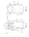
- FIG. 1 illustrates a blocking member 10 of the present invention.
- the blocking member 10 comprises a hollow, central body 20 having a first end 12 and a second end 16.
- the central body 20 is preferably tapered from a first end 15 to a second end 16.
- the central body 20 further comprises optional barbs 9 which preferably extend like fins from the hollow body and function to secure the blocking device in the vent bores to prevent pullout during demolding.
- the central body 20 may be formed of two halves 20a, 20b which are divided by longitudinal openings 3, 4.
- the openings provide the central body free mobility in the radial direction during insertion of the device into a mold vent bore (not shown). The openings close as the blocking device is inserted into the mold vent bores.
- the blocking member 10 is preferably formed from a single thin sheet of metal stock, and may be formed from stamping or punching the metal and then bending the metal into the desired profile.
- the blocking member is formed from a one piece sheet of metal.
- the diameter of the blocking member is preferably in a range of from 2.5 to 3 mm.
- the first end of the blocking member 10 comprises a cap 30.
- the inner portion 32 of the cap is preferably circular and flat, and is surrounded by an annular depression 34.
- the cap further includes an annular rim 12 that may be flush with the inner portion 32.
- the rim 12 may further include optional tabs 41 which extend from the rim 12 in order to prevent the blocking member 12 from being pushed too far in the mold bore.
- a sidewall 36 connects the inner portion 32 to the annular depression 34.
- the sidewall has one or more slots 40 for venting the mold gasses from the mold.
- the slots are preferably positioned to be 90 degrees with respect to the flow direction of the rubber to avoid plugging.
- the slots are preferably sized to have an opening with the smallest dimension or thickness in the range of 0.05 to 0.1 mm.
- the slot openings preferably have a width of in a range of from 0.1 mm to 0.6 mm.
- the surface 32 may be flush with the outer rim 12.
- the trapped mold gasses must travel 90 degrees down the sidewalls 36 of the cap surface 32 and then bend another 90 degrees into slots 40.
- the double bend of the flow path acts as a labyrinth in order to block the rubber from flowing past the cap.
Landscapes
- Engineering & Computer Science (AREA)
- Mechanical Engineering (AREA)
- Moulds For Moulding Plastics Or The Like (AREA)
Abstract
Description
- The invention relates to a blocking member for vent bores in molds for the manufacture of rubber products such as tires. More particularly, the invention is directed to a mold which is equipped with one or more such blocking members.
- There are generally two types of molds used in the production of rubber articles, such as tires. The first type is the ventless type wherein the mold gasses are vented through tiny cracks in the mold surfaces. The second type of mold is the vented type which comprises a plurality of venting bores in which pins or other devices are inserted to block the flow of rubber while venting the mold. The blocking devices allow the air and mold gasses to vent while preventing the flow of rubber. Without the blocking devices, tiny spues or rubber shoots form on the surface of the article resulting in a hedge hog or bristled appearance. Prior art blocking devices such as shown in
DE-A- 19900596 orDE-A- 10344912 may stop the formation of these rubber shoots, but may result in marks on the surface of the tire. Thus it is desired to have an improved blocking device which allows the gasses to be vented without the formation of rubber shoots and without marks being formed on the tires. - The invention relates to a mold blocking member according to claim 1 and a tire mold according to
claim 15. - Dependent claims refer to preferred embodiments of the invention.
- It is preferred that the inner portion is flat and recessed with respect to the outer rim of the first end.
- The invention will be described by way of example and with reference to the accompanying drawings in which:
-
FIG. 1 is a front, perspective view of a blocking device of the present invention; -
FIG. 2 is a bottom perspective view of the blocking device in the direction 2-2 ofFigure 1 ; and -
FIG. 3 is an end view of the blocking device in the direction 2-2 ofFigure 1 . -
FIG. 4 illustrates the air path of the blocking device inserted in a mold bore. -
Figure 1 illustrates a blockingmember 10 of the present invention. The blockingmember 10 comprises a hollow,central body 20 having afirst end 12 and asecond end 16. Thecentral body 20 is preferably tapered from afirst end 15 to asecond end 16. Thecentral body 20 further comprisesoptional barbs 9 which preferably extend like fins from the hollow body and function to secure the blocking device in the vent bores to prevent pullout during demolding. - The
central body 20 may be formed of twohalves longitudinal openings - The blocking
member 10 is preferably formed from a single thin sheet of metal stock, and may be formed from stamping or punching the metal and then bending the metal into the desired profile. Preferably the blocking member is formed from a one piece sheet of metal. The diameter of the blocking member is preferably in a range of from 2.5 to 3 mm. - The first end of the blocking
member 10 comprises acap 30. Theinner portion 32 of the cap is preferably circular and flat, and is surrounded by anannular depression 34. The cap further includes anannular rim 12 that may be flush with theinner portion 32. Therim 12 may further includeoptional tabs 41 which extend from therim 12 in order to prevent the blockingmember 12 from being pushed too far in the mold bore. A sidewall 36 connects theinner portion 32 to theannular depression 34. The sidewall has one ormore slots 40 for venting the mold gasses from the mold. The slots are preferably positioned to be 90 degrees with respect to the flow direction of the rubber to avoid plugging. The slots are preferably sized to have an opening with the smallest dimension or thickness in the range of 0.05 to 0.1 mm. The slot openings preferably have a width of in a range of from 0.1 mm to 0.6 mm. Thesurface 32 may be flush with theouter rim 12. - As shown in
Fig. 4 , the trapped mold gasses must travel 90 degrees down the sidewalls 36 of thecap surface 32 and then bend another 90 degrees intoslots 40. The double bend of the flow path acts as a labyrinth in order to block the rubber from flowing past the cap.
Claims (15)
- A mold blocking member for use in a vent bore of a mold for the manufacture of rubber products, the mold blocking member (10) comprising a central body (20) having a first end (15) and a second end (16), wherein the first end (15) has a cap (30) with an inner portion (32) surrounded by a recessed annular portion (34), wherein the inner portion (32) is connected to the recessed annular portion (34) by a sidewall (36), the sidewall (36) having one or more openings (40) therein.
- The mold blocking member of claim 1 wherein the openings (40) are slots.
- The mold blocking member of at least one of the previous claims wherein the central body (20) is tubular hollow body.
- The mold blocking member of at least one of the previous claims wherein the openings or slot openings have a minimum dimension in the range of from 0.03 mm to 0.15 mm and/or wherein the openings or slot openings have a width dimension in the range of from 0.1 mm to 0.6 mm.
- The mold blocking member of at least one of the previous claims wherein the inner portion (32) is flat and preferably free of openings or slots.
- The mold blocking member of at least one of the previous claims wherein the inner portion (32) is recessed with respect to an outer rim of the first end (15).
- The mold blocking member of at least one of the previous claims wherein the sidewall (36) has a plurality, particularly three or four, of preferably equidistant slots (40) therein, wherein the height of each of the slots is in a range of from 60 to 90 % of the height of the sidewall (36) and/or wherein the circumferential length of each of the slots (40) is in a range of from 5 to 20%, alternatively 10 % to 15 %, of the circumferential length of the sidewall (36).
- The mold blocking member of at least one of the previous claims wherein the inner portion (32) is flush with respect to an outer rim of the first end (15).
- The mold blocking member of at least one of the previous claims wherein the mold blocking member (10) consists of only one piece or wherein the mold blocking member (10) is made from a single thin sheet of metal stock such as steel or aluminum stock.
- The mold blocking member of at least one of the previous claims wherein the diameter of the central body (20) is in a range of from 1.5 to 4mm, preferably 2.5 to 3 mm.
- The mold blocking member of at least one of the previous claims wherein the central body (20) is tapered from the first end (15) to the second end (16).
- The mold blocking member of at least one of the previous claims wherein the central body (20) includes two portions or halves (20a, 20b) which are separated by longitudinal openings (3, 4) or slots.
- The mold blocking member of at least one of the previous claims wherein the central body (20) comprises at least one barb (9) preferably extending like a fin from the central body (20) to secure the mold blocking member (10) in a vent bore in a mold.
- The mold blocking member of at least one of the previous claims wherein the central body (20) or the outer rim of the first end (15) comprises at least one tab (41) for preventing the mold blocking member (10) from being pushed to far in a vent bore in a mold.
- A tire mold comprising a plurality of mold blocking members (10) according to one of the previous claims inserted in vent bores in the mold.
Applications Claiming Priority (1)
| Application Number | Priority Date | Filing Date | Title |
|---|---|---|---|
| US12/334,872 US7811078B2 (en) | 2008-12-15 | 2008-12-15 | Venting device for mold |
Publications (2)
| Publication Number | Publication Date |
|---|---|
| EP2199070A1 true EP2199070A1 (en) | 2010-06-23 |
| EP2199070B1 EP2199070B1 (en) | 2011-07-20 |
Family
ID=41786290
Family Applications (1)
| Application Number | Title | Priority Date | Filing Date |
|---|---|---|---|
| EP09177817A Not-in-force EP2199070B1 (en) | 2008-12-15 | 2009-12-03 | Venting device for mold |
Country Status (3)
| Country | Link |
|---|---|
| US (1) | US7811078B2 (en) |
| EP (1) | EP2199070B1 (en) |
| AT (1) | ATE516948T1 (en) |
Families Citing this family (2)
| Publication number | Priority date | Publication date | Assignee | Title |
|---|---|---|---|---|
| EP3092113A4 (en) * | 2014-01-09 | 2017-10-11 | Bridgestone Americas Tire Operations, LLC | Tire mold vent |
| US11007735B2 (en) | 2019-08-08 | 2021-05-18 | The Goodyear Tire & Rubber Company | Tire mold |
Citations (3)
| Publication number | Priority date | Publication date | Assignee | Title |
|---|---|---|---|---|
| DE19833730A1 (en) * | 1998-07-27 | 2000-02-03 | Dunlop Gmbh | Valved air vent used in tire vulcanization mold is made of only two parts, gripping into bore in mold and sealing at internal surface when green tire contacts domed resilient disc, in simple trouble-free design |
| EP1314526A2 (en) * | 2001-11-14 | 2003-05-28 | The Goodyear Tire & Rubber Company | Vulcanization mold for the manufacture of technical rubber products |
| JP2005028589A (en) * | 2003-07-07 | 2005-02-03 | Yokohama Rubber Co Ltd:The | Tire mold, plug used in vent hole thereof and tire manufactured using tire mold |
Family Cites Families (9)
| Publication number | Priority date | Publication date | Assignee | Title |
|---|---|---|---|---|
| US3374983A (en) * | 1965-08-09 | 1968-03-26 | Molded Glass Company | Concrete form stripping valve |
| US4026512A (en) * | 1975-07-28 | 1977-05-31 | Kenneth Holt | Static mold vent |
| NL7610516A (en) * | 1975-09-30 | 1977-04-01 | Sekisui Plastics | STEAM DRAINING DEVICE. |
| US4795331A (en) * | 1986-09-15 | 1989-01-03 | The Goodyear Tire & Rubber Company | Mold vent plug |
| DE19628166C2 (en) * | 1996-07-12 | 1999-06-24 | Continental Ag | Process for the production of a pin for venting mold troughs during the shaping and / or vulcanization of rubber articles |
| AU750088C (en) * | 1998-07-27 | 2003-06-12 | Dunlop Gmbh | Tyre vulcanisation mould with blocking mechanisms fitted in de-airing holes |
| JP3589644B2 (en) * | 2000-12-07 | 2004-11-17 | 日本碍子株式会社 | Tire mold |
| DE10344912A1 (en) * | 2003-09-26 | 2005-04-21 | Goodyear Tire & Rubber | Barrier device for venting holes in vulcanization molds for the manufacture of technical rubber products and with vulcanization molds provided with blocking elements |
| US7530803B2 (en) * | 2007-05-08 | 2009-05-12 | Bridgestone Firestone North American Tire, Llc | Insert for a tire mold vent |
-
2008
- 2008-12-15 US US12/334,872 patent/US7811078B2/en not_active Expired - Fee Related
-
2009
- 2009-12-03 AT AT09177817T patent/ATE516948T1/en not_active IP Right Cessation
- 2009-12-03 EP EP09177817A patent/EP2199070B1/en not_active Not-in-force
Patent Citations (3)
| Publication number | Priority date | Publication date | Assignee | Title |
|---|---|---|---|---|
| DE19833730A1 (en) * | 1998-07-27 | 2000-02-03 | Dunlop Gmbh | Valved air vent used in tire vulcanization mold is made of only two parts, gripping into bore in mold and sealing at internal surface when green tire contacts domed resilient disc, in simple trouble-free design |
| EP1314526A2 (en) * | 2001-11-14 | 2003-05-28 | The Goodyear Tire & Rubber Company | Vulcanization mold for the manufacture of technical rubber products |
| JP2005028589A (en) * | 2003-07-07 | 2005-02-03 | Yokohama Rubber Co Ltd:The | Tire mold, plug used in vent hole thereof and tire manufactured using tire mold |
Also Published As
| Publication number | Publication date |
|---|---|
| US7811078B2 (en) | 2010-10-12 |
| ATE516948T1 (en) | 2011-08-15 |
| EP2199070B1 (en) | 2011-07-20 |
| US20100148032A1 (en) | 2010-06-17 |
Similar Documents
| Publication | Publication Date | Title |
|---|---|---|
| EP2199048B1 (en) | Venting device for mold | |
| US9920826B2 (en) | Hollow rack bar and method of manufacturing hollow rack bar | |
| PT987094E (en) | PROCESS FOR THE MANUFACTURE OF PACKAGING | |
| KR100476248B1 (en) | Method of manufacturing heat exchanging fin and die set for manufacturing the same | |
| USD937190S1 (en) | Tire sidewall | |
| EP2199070B1 (en) | Venting device for mold | |
| USD952547S1 (en) | Tire sidewall | |
| EP1254750A3 (en) | Tire mold | |
| EP2332710B1 (en) | Venting device for a mold | |
| US10596731B2 (en) | Stencil plate for tire, tire vulcanization mold and manufacturing method of tire using the same | |
| EP2554349B1 (en) | Mold venting assembly | |
| JP2007503317A (en) | Method and system for forming cam-engaged rocker arm | |
| CN102092109B (en) | Exhaust apparatus for die | |
| EP1634661A4 (en) | Multiple tube, and method and apparatus for manufacturing multiple tube | |
| JP2021020236A5 (en) | ||
| CN219425491U (en) | Novel blowing mode drift convenient to drawing of patterns | |
| USD1003818S1 (en) | Tire sidewall | |
| CN209021065U (en) | Bearing snap spring progressive die formed punch | |
| US10737452B2 (en) | Tire vulcanization mold and tire manufacturing method using the same | |
| JP4210232B2 (en) | Insert part molding method and insert part | |
| ITTO970082A1 (en) | METHOD OF MANUFACTURE OF A SHEET METAL FAN AND RELATIVE FAN SO MANUFACTURED | |
| CN110586754B (en) | Method for producing a synchronizer ring and synchronizer ring | |
| CN203778607U (en) | Fixed-type movable punching die | |
| KR101575098B1 (en) | Method for manufacturing of muffler | |
| JP2004344970A (en) | Cylindrical supporting bar used for head rest or the like, punch for manufacturing the cylindrical supporting bar, and method for manufacturing the cylindrical supporting bar |
Legal Events
| Date | Code | Title | Description |
|---|---|---|---|
| PUAI | Public reference made under article 153(3) epc to a published international application that has entered the european phase |
Free format text: ORIGINAL CODE: 0009012 |
|
| AK | Designated contracting states |
Kind code of ref document: A1 Designated state(s): AT BE BG CH CY CZ DE DK EE ES FI FR GB GR HR HU IE IS IT LI LT LU LV MC MK MT NL NO PL PT RO SE SI SK SM TR |
|
| AX | Request for extension of the european patent |
Extension state: AL BA RS |
|
| GRAP | Despatch of communication of intention to grant a patent |
Free format text: ORIGINAL CODE: EPIDOSNIGR1 |
|
| 17P | Request for examination filed |
Effective date: 20101223 |
|
| RIC1 | Information provided on ipc code assigned before grant |
Ipc: B29D 30/06 20060101AFI20110118BHEP Ipc: B29C 33/10 20060101ALI20110118BHEP Ipc: B29C 35/02 20060101ALI20110118BHEP |
|
| GRAS | Grant fee paid |
Free format text: ORIGINAL CODE: EPIDOSNIGR3 |
|
| GRAA | (expected) grant |
Free format text: ORIGINAL CODE: 0009210 |
|
| AK | Designated contracting states |
Kind code of ref document: B1 Designated state(s): AT BE BG CH CY CZ DE DK EE ES FI FR GB GR HR HU IE IS IT LI LT LU LV MC MK MT NL NO PL PT RO SE SI SK SM TR |
|
| REG | Reference to a national code |
Ref country code: GB Ref legal event code: FG4D |
|
| REG | Reference to a national code |
Ref country code: CH Ref legal event code: EP |
|
| REG | Reference to a national code |
Ref country code: DE Ref legal event code: R096 Ref document number: 602009001874 Country of ref document: DE Effective date: 20110915 |
|
| REG | Reference to a national code |
Ref country code: NL Ref legal event code: VDEP Effective date: 20110720 |
|
| REG | Reference to a national code |
Ref country code: AT Ref legal event code: MK05 Ref document number: 516948 Country of ref document: AT Kind code of ref document: T Effective date: 20110720 |
|
| PG25 | Lapsed in a contracting state [announced via postgrant information from national office to epo] |
Ref country code: FI Free format text: LAPSE BECAUSE OF FAILURE TO SUBMIT A TRANSLATION OF THE DESCRIPTION OR TO PAY THE FEE WITHIN THE PRESCRIBED TIME-LIMIT Effective date: 20110720 Ref country code: NO Free format text: LAPSE BECAUSE OF FAILURE TO SUBMIT A TRANSLATION OF THE DESCRIPTION OR TO PAY THE FEE WITHIN THE PRESCRIBED TIME-LIMIT Effective date: 20111020 Ref country code: IS Free format text: LAPSE BECAUSE OF FAILURE TO SUBMIT A TRANSLATION OF THE DESCRIPTION OR TO PAY THE FEE WITHIN THE PRESCRIBED TIME-LIMIT Effective date: 20111120 Ref country code: SE Free format text: LAPSE BECAUSE OF FAILURE TO SUBMIT A TRANSLATION OF THE DESCRIPTION OR TO PAY THE FEE WITHIN THE PRESCRIBED TIME-LIMIT Effective date: 20110720 Ref country code: HR Free format text: LAPSE BECAUSE OF FAILURE TO SUBMIT A TRANSLATION OF THE DESCRIPTION OR TO PAY THE FEE WITHIN THE PRESCRIBED TIME-LIMIT Effective date: 20110720 Ref country code: NL Free format text: LAPSE BECAUSE OF FAILURE TO SUBMIT A TRANSLATION OF THE DESCRIPTION OR TO PAY THE FEE WITHIN THE PRESCRIBED TIME-LIMIT Effective date: 20110720 Ref country code: LT Free format text: LAPSE BECAUSE OF FAILURE TO SUBMIT A TRANSLATION OF THE DESCRIPTION OR TO PAY THE FEE WITHIN THE PRESCRIBED TIME-LIMIT Effective date: 20110720 Ref country code: PT Free format text: LAPSE BECAUSE OF FAILURE TO SUBMIT A TRANSLATION OF THE DESCRIPTION OR TO PAY THE FEE WITHIN THE PRESCRIBED TIME-LIMIT Effective date: 20111121 Ref country code: BE Free format text: LAPSE BECAUSE OF FAILURE TO SUBMIT A TRANSLATION OF THE DESCRIPTION OR TO PAY THE FEE WITHIN THE PRESCRIBED TIME-LIMIT Effective date: 20110720 |
|
| PG25 | Lapsed in a contracting state [announced via postgrant information from national office to epo] |
Ref country code: GR Free format text: LAPSE BECAUSE OF FAILURE TO SUBMIT A TRANSLATION OF THE DESCRIPTION OR TO PAY THE FEE WITHIN THE PRESCRIBED TIME-LIMIT Effective date: 20111021 Ref country code: SI Free format text: LAPSE BECAUSE OF FAILURE TO SUBMIT A TRANSLATION OF THE DESCRIPTION OR TO PAY THE FEE WITHIN THE PRESCRIBED TIME-LIMIT Effective date: 20110720 Ref country code: CY Free format text: LAPSE BECAUSE OF FAILURE TO SUBMIT A TRANSLATION OF THE DESCRIPTION OR TO PAY THE FEE WITHIN THE PRESCRIBED TIME-LIMIT Effective date: 20110720 Ref country code: AT Free format text: LAPSE BECAUSE OF FAILURE TO SUBMIT A TRANSLATION OF THE DESCRIPTION OR TO PAY THE FEE WITHIN THE PRESCRIBED TIME-LIMIT Effective date: 20110720 Ref country code: LV Free format text: LAPSE BECAUSE OF FAILURE TO SUBMIT A TRANSLATION OF THE DESCRIPTION OR TO PAY THE FEE WITHIN THE PRESCRIBED TIME-LIMIT Effective date: 20110720 Ref country code: PL Free format text: LAPSE BECAUSE OF FAILURE TO SUBMIT A TRANSLATION OF THE DESCRIPTION OR TO PAY THE FEE WITHIN THE PRESCRIBED TIME-LIMIT Effective date: 20110720 |
|
| PG25 | Lapsed in a contracting state [announced via postgrant information from national office to epo] |
Ref country code: CZ Free format text: LAPSE BECAUSE OF FAILURE TO SUBMIT A TRANSLATION OF THE DESCRIPTION OR TO PAY THE FEE WITHIN THE PRESCRIBED TIME-LIMIT Effective date: 20110720 Ref country code: SK Free format text: LAPSE BECAUSE OF FAILURE TO SUBMIT A TRANSLATION OF THE DESCRIPTION OR TO PAY THE FEE WITHIN THE PRESCRIBED TIME-LIMIT Effective date: 20110720 |
|
| PLBE | No opposition filed within time limit |
Free format text: ORIGINAL CODE: 0009261 |
|
| STAA | Information on the status of an ep patent application or granted ep patent |
Free format text: STATUS: NO OPPOSITION FILED WITHIN TIME LIMIT |
|
| PG25 | Lapsed in a contracting state [announced via postgrant information from national office to epo] |
Ref country code: RO Free format text: LAPSE BECAUSE OF FAILURE TO SUBMIT A TRANSLATION OF THE DESCRIPTION OR TO PAY THE FEE WITHIN THE PRESCRIBED TIME-LIMIT Effective date: 20110720 Ref country code: EE Free format text: LAPSE BECAUSE OF FAILURE TO SUBMIT A TRANSLATION OF THE DESCRIPTION OR TO PAY THE FEE WITHIN THE PRESCRIBED TIME-LIMIT Effective date: 20110720 |
|
| 26N | No opposition filed |
Effective date: 20120423 |
|
| PG25 | Lapsed in a contracting state [announced via postgrant information from national office to epo] |
Ref country code: DK Free format text: LAPSE BECAUSE OF FAILURE TO SUBMIT A TRANSLATION OF THE DESCRIPTION OR TO PAY THE FEE WITHIN THE PRESCRIBED TIME-LIMIT Effective date: 20110720 |
|
| PG25 | Lapsed in a contracting state [announced via postgrant information from national office to epo] |
Ref country code: MC Free format text: LAPSE BECAUSE OF NON-PAYMENT OF DUE FEES Effective date: 20111231 |
|
| REG | Reference to a national code |
Ref country code: DE Ref legal event code: R097 Ref document number: 602009001874 Country of ref document: DE Effective date: 20120423 |
|
| REG | Reference to a national code |
Ref country code: IE Ref legal event code: MM4A |
|
| PG25 | Lapsed in a contracting state [announced via postgrant information from national office to epo] |
Ref country code: IE Free format text: LAPSE BECAUSE OF NON-PAYMENT OF DUE FEES Effective date: 20111203 |
|
| PG25 | Lapsed in a contracting state [announced via postgrant information from national office to epo] |
Ref country code: MT Free format text: LAPSE BECAUSE OF FAILURE TO SUBMIT A TRANSLATION OF THE DESCRIPTION OR TO PAY THE FEE WITHIN THE PRESCRIBED TIME-LIMIT Effective date: 20110720 Ref country code: MK Free format text: LAPSE BECAUSE OF FAILURE TO SUBMIT A TRANSLATION OF THE DESCRIPTION OR TO PAY THE FEE WITHIN THE PRESCRIBED TIME-LIMIT Effective date: 20110720 |
|
| PG25 | Lapsed in a contracting state [announced via postgrant information from national office to epo] |
Ref country code: ES Free format text: LAPSE BECAUSE OF FAILURE TO SUBMIT A TRANSLATION OF THE DESCRIPTION OR TO PAY THE FEE WITHIN THE PRESCRIBED TIME-LIMIT Effective date: 20111031 Ref country code: SM Free format text: LAPSE BECAUSE OF FAILURE TO SUBMIT A TRANSLATION OF THE DESCRIPTION OR TO PAY THE FEE WITHIN THE PRESCRIBED TIME-LIMIT Effective date: 20110720 |
|
| PG25 | Lapsed in a contracting state [announced via postgrant information from national office to epo] |
Ref country code: LU Free format text: LAPSE BECAUSE OF NON-PAYMENT OF DUE FEES Effective date: 20111203 |
|
| PG25 | Lapsed in a contracting state [announced via postgrant information from national office to epo] |
Ref country code: BG Free format text: LAPSE BECAUSE OF FAILURE TO SUBMIT A TRANSLATION OF THE DESCRIPTION OR TO PAY THE FEE WITHIN THE PRESCRIBED TIME-LIMIT Effective date: 20111020 |
|
| PG25 | Lapsed in a contracting state [announced via postgrant information from national office to epo] |
Ref country code: TR Free format text: LAPSE BECAUSE OF FAILURE TO SUBMIT A TRANSLATION OF THE DESCRIPTION OR TO PAY THE FEE WITHIN THE PRESCRIBED TIME-LIMIT Effective date: 20110720 |
|
| PG25 | Lapsed in a contracting state [announced via postgrant information from national office to epo] |
Ref country code: HU Free format text: LAPSE BECAUSE OF FAILURE TO SUBMIT A TRANSLATION OF THE DESCRIPTION OR TO PAY THE FEE WITHIN THE PRESCRIBED TIME-LIMIT Effective date: 20110720 |
|
| REG | Reference to a national code |
Ref country code: CH Ref legal event code: PL |
|
| GBPC | Gb: european patent ceased through non-payment of renewal fee |
Effective date: 20131203 |
|
| PG25 | Lapsed in a contracting state [announced via postgrant information from national office to epo] |
Ref country code: LI Free format text: LAPSE BECAUSE OF NON-PAYMENT OF DUE FEES Effective date: 20131231 Ref country code: CH Free format text: LAPSE BECAUSE OF NON-PAYMENT OF DUE FEES Effective date: 20131231 |
|
| PG25 | Lapsed in a contracting state [announced via postgrant information from national office to epo] |
Ref country code: GB Free format text: LAPSE BECAUSE OF NON-PAYMENT OF DUE FEES Effective date: 20131203 |
|
| REG | Reference to a national code |
Ref country code: FR Ref legal event code: PLFP Year of fee payment: 7 |
|
| REG | Reference to a national code |
Ref country code: FR Ref legal event code: PLFP Year of fee payment: 8 |
|
| PGFP | Annual fee paid to national office [announced via postgrant information from national office to epo] |
Ref country code: IT Payment date: 20161221 Year of fee payment: 8 |
|
| REG | Reference to a national code |
Ref country code: FR Ref legal event code: PLFP Year of fee payment: 9 |
|
| REG | Reference to a national code |
Ref country code: FR Ref legal event code: PLFP Year of fee payment: 10 |
|
| PG25 | Lapsed in a contracting state [announced via postgrant information from national office to epo] |
Ref country code: IT Free format text: LAPSE BECAUSE OF NON-PAYMENT OF DUE FEES Effective date: 20171203 |
|
| PGFP | Annual fee paid to national office [announced via postgrant information from national office to epo] |
Ref country code: DE Payment date: 20201118 Year of fee payment: 12 Ref country code: FR Payment date: 20201013 Year of fee payment: 12 |
|
| REG | Reference to a national code |
Ref country code: DE Ref legal event code: R119 Ref document number: 602009001874 Country of ref document: DE |
|
| PG25 | Lapsed in a contracting state [announced via postgrant information from national office to epo] |
Ref country code: DE Free format text: LAPSE BECAUSE OF NON-PAYMENT OF DUE FEES Effective date: 20220701 |
|
| PG25 | Lapsed in a contracting state [announced via postgrant information from national office to epo] |
Ref country code: FR Free format text: LAPSE BECAUSE OF NON-PAYMENT OF DUE FEES Effective date: 20211231 |