EP2332209B1 - Stabilisation d'un mât pour des véhicules et des bateaux - Google Patents
Stabilisation d'un mât pour des véhicules et des bateaux Download PDFInfo
- Publication number
- EP2332209B1 EP2332209B1 EP09736090.3A EP09736090A EP2332209B1 EP 2332209 B1 EP2332209 B1 EP 2332209B1 EP 09736090 A EP09736090 A EP 09736090A EP 2332209 B1 EP2332209 B1 EP 2332209B1
- Authority
- EP
- European Patent Office
- Prior art keywords
- mast
- carrier
- cable
- longitudinal direction
- vehicle
- Prior art date
- Legal status (The legal status is an assumption and is not a legal conclusion. Google has not performed a legal analysis and makes no representation as to the accuracy of the status listed.)
- Not-in-force
Links
- 230000006641 stabilisation Effects 0.000 title claims description 12
- 238000011105 stabilization Methods 0.000 title claims description 12
- 230000001133 acceleration Effects 0.000 claims description 26
- 230000033001 locomotion Effects 0.000 claims description 25
- 238000000034 method Methods 0.000 claims description 9
- 230000000903 blocking effect Effects 0.000 claims description 7
- 238000012544 monitoring process Methods 0.000 claims description 4
- 238000010586 diagram Methods 0.000 description 7
- 230000000087 stabilizing effect Effects 0.000 description 6
- 230000008859 change Effects 0.000 description 5
- 230000008878 coupling Effects 0.000 description 4
- 238000010168 coupling process Methods 0.000 description 4
- 238000005859 coupling reaction Methods 0.000 description 4
- 230000003287 optical effect Effects 0.000 description 4
- 238000004891 communication Methods 0.000 description 3
- 238000013461 design Methods 0.000 description 3
- 238000005096 rolling process Methods 0.000 description 3
- 229910000831 Steel Inorganic materials 0.000 description 2
- 238000010276 construction Methods 0.000 description 2
- 230000007246 mechanism Effects 0.000 description 2
- 239000010959 steel Substances 0.000 description 2
- 241000220010 Rhode Species 0.000 description 1
- 239000000969 carrier Substances 0.000 description 1
- 238000001514 detection method Methods 0.000 description 1
- 230000000694 effects Effects 0.000 description 1
- 239000000835 fiber Substances 0.000 description 1
- 238000012986 modification Methods 0.000 description 1
- 230000004048 modification Effects 0.000 description 1
- 230000008569 process Effects 0.000 description 1
- 230000007363 regulatory process Effects 0.000 description 1
- XLYOFNOQVPJJNP-UHFFFAOYSA-N water Substances O XLYOFNOQVPJJNP-UHFFFAOYSA-N 0.000 description 1
Images


Classifications
-
- H—ELECTRICITY
- H01—ELECTRIC ELEMENTS
- H01Q—ANTENNAS, i.e. RADIO AERIALS
- H01Q1/00—Details of, or arrangements associated with, antennas
- H01Q1/12—Supports; Mounting means
- H01Q1/18—Means for stabilising antennas on an unstable platform
-
- H—ELECTRICITY
- H01—ELECTRIC ELEMENTS
- H01Q—ANTENNAS, i.e. RADIO AERIALS
- H01Q1/00—Details of, or arrangements associated with, antennas
- H01Q1/08—Means for collapsing antennas or parts thereof
- H01Q1/10—Telescopic elements
-
- H—ELECTRICITY
- H01—ELECTRIC ELEMENTS
- H01Q—ANTENNAS, i.e. RADIO AERIALS
- H01Q1/00—Details of, or arrangements associated with, antennas
- H01Q1/12—Supports; Mounting means
- H01Q1/1235—Collapsible supports; Means for erecting a rigid antenna
-
- H—ELECTRICITY
- H01—ELECTRIC ELEMENTS
- H01Q—ANTENNAS, i.e. RADIO AERIALS
- H01Q1/00—Details of, or arrangements associated with, antennas
- H01Q1/27—Adaptation for use in or on movable bodies
- H01Q1/32—Adaptation for use in or on road or rail vehicles
- H01Q1/3208—Adaptation for use in or on road or rail vehicles characterised by the application wherein the antenna is used
- H01Q1/3216—Adaptation for use in or on road or rail vehicles characterised by the application wherein the antenna is used where the road or rail vehicle is only used as transportation means
-
- H—ELECTRICITY
- H01—ELECTRIC ELEMENTS
- H01Q—ANTENNAS, i.e. RADIO AERIALS
- H01Q1/00—Details of, or arrangements associated with, antennas
- H01Q1/27—Adaptation for use in or on movable bodies
- H01Q1/34—Adaptation for use in or on ships, submarines, buoys or torpedoes
Definitions
- the present invention relates to a system for stabilizing the alignment of a mast on a mobile support, e.g. a land vehicle or a ship, and a corresponding procedure.
- a mobile support e.g. a land vehicle or a ship
- Transportable, extendable telescopic masts for reconnaissance vehicles are known from the prior art, which make it possible to position a payload at a variable height above the vehicle.
- the payload can be a sensor head with various monitoring and communication devices, eg with a communication antenna, an antenna of a reconnaissance radar, one or more cameras etc.
- Such a mast is eg in the WO 2005/099029 specified.
- the carrier vehicle is stationary and stationary as long as the mast is extended.
- the mast is retracted and then folded away, for example, stowed on the roof of the carrier vehicle or sunk into a storage space of the carrier vehicle.
- a payload such as a radar antenna against the rolling and pitching movements of the ship.
- the payload is located on a movable platform, which is passive (eg by centrifugal forces) or actively stabilized by a corresponding control loop with sensors and actuators.
- a variety of mechanical arrangements have been proposed, such as in the US 5,922,039 or US 4,647,939 . Regulatory processes for the active stabilization of such a platform have been described, for example, in US Pat WO 99/04224 or the EP 0 107 232 proposed.
- the stabilized platform directly supports the payload.
- such arrangements are generally unsuitable for stabilizing a payload on a telescopic mast because of their weight and size.
- the safety device can be used to relieve the actuator device during rapid braking of the vehicle in the short term of the inertial forces caused thereby.
- the actuator device can thereby be optimized so that it can change the longitudinal direction of the mast sufficiently quickly to follow changes in orientation of the carrier, without the actuator must absorb all forces acting on the mast forces in all operating conditions.
- the securing device can be designed in particular as a cable pull system.
- This comprises at least one safety rope, which extends between the mast and the carrier and is preferably connected to the mast above the mast bearing, and at least one cable guide device on which the safety rope is guided and the rope when exceeding a predetermined acceleration value on the mast and / or occurs on the carrier, blocked in such a way that further pivoting of the mast is prevented.
- an electrically actuated clutch or a mechanical clutch can be used.
- the cable guide device then preferably has at least one cable drum with a spring element, wherein the cable drum is adapted to be connected to the carrier, and wherein the Rope can be prestressed by means of the spring element.
- the spring element may for example be a coil spring.
- the mast is stabilized not only about a single pivot axis, but about two preferably mutually orthogonal pivot axes.
- the mast bearing is designed such that it allows a pivoting movement of the mast about two mutually orthogonal pivot axes.
- the mast sensor device is designed to detect the longitudinal direction of the mast with respect to both pivot axes, and the actuator device is designed to pivot the mast about both pivot axes. Accordingly, the controller is then formed two-dimensionally, i. it receives a two-dimensional controlled variable and generates a two-dimensional control variable, or there are two one-dimensional controller.
- the mast bearing may in particular comprise a universal joint or a ball joint. Preferably, it is designed such that it blocks a rotation of the mast about its longitudinal direction.
- the mast is preferably a telescopic mast with a plurality of mast segments movable relative to each other along the longitudinal direction. Such masts are known in a variety of configurations of the prior art. The invention is also applicable to one-piece masts.
- the mast sensor device preferably comprises at least one gyroscope.
- This may be a mechanical gyroscope, an optical gyroscope or a vibrating gyroscope.
- the gyro is drift-compensated in a known manner.
- the system may comprise a carrier sensor device which is designed to detect the orientation of the carrier with respect to the predetermined spatial direction.
- the control device is then designed to additionally receive direction signals from the carrier sensor device and to take them into account when determining the manipulated variable.
- the actuator device has at least one cable pull system.
- This comprises a pull rope which extends between the mast and the support and is preferably connected to the mast above the mast bearing, and at least one cable drive adapted to drive the pull rope to move, thereby moving the mast with its longitudinal direction to pivot relative to the carrier.
- the securing device may comprise a coupling of the cable drive, which blocks the pull rope when a predetermined acceleration is exceeded.
- a separately formed safety device is present, as described above.
- the actuator device has at least one spindle drive.
- This comprises a threaded spindle and a drive device, which is designed to enable the threaded spindle and a threaded nut in a relative rotation to each other, wherein the rotation causes a pivoting of the mast relative to the carrier.
- the system according to the invention is used on a land vehicle or a ship as a carrier and is accordingly adapted in its dimensions and the nature of its construction to such an application specifically.
- the invention is also directed to a vehicle, in particular a land or water vehicle, with such a system.
- the vehicle usually defines a vehicle longitudinal direction by its main movement direction, and the securing device is then preferably designed to block the mast when a predetermined acceleration value is exceeded, at least with respect to pivoting movements in the vehicle longitudinal direction.
- a method for active stabilization of a mast in particular a telescopic mast, having the features of claim 14 is given.
- the blocking can be done with a safety device as described above or otherwise.
- a vehicle 2 is shown with a telescopic mast 3 mounted therein. Based on this figure, the basic structure of a stabilization system according to the invention and the directions used in this document are explained.
- the vehicle 2 defines with its chassis 21 a vehicle longitudinal axis, which is referred to as the X direction ( Fig. 1 (a) ).
- the vehicle transverse axis is referred to as the Y direction ( Fig. 1 (b) ).
- Perpendicular to these two directions runs the vehicle vertical axis, which is referred to as Z-direction.
- the X, Y and Z directions together form a vehicle-fixed coordinate system.
- the telescopic mast 3 is composed of several mast segments, in the present example, three mast segments 31, 32 and 33. Of course, depending on the construction of the telescopic mast more or less mast segments may be present (in practice usually four or more).
- the mast segments are displaceable against each other along a longitudinal axis 34.
- any mechanism can be used, as it is known from the prior art, for example a cable mechanism as in the already mentioned WO 2005/099029 or a suitable spindle drive.
- the uppermost, here third, mast segment 33 carries a payload 4.
- This may in particular be a communication antenna, a radar antenna, an optical sensor or any other type of payload, as is commonly used in reconnaissance vehicles on telescopic masts. It goes without saying that the present invention is not limited to a particular type of payload.
- the first, lowest pole segment 31 is held in a mast bearing 5, which is rigidly connected to the chassis 21 of the vehicle 2.
- the mast bearing 5 allows pivotal movements of the longitudinal axis 34 of the mast 3 both about the vehicle longitudinal axis X and about the vehicle transverse axis Y.
- the mast bearing for example. be designed as a universal joint or as a ball joint, as is well known from the prior art. If the mast bearing is designed as a ball joint, a torsional movement about the mast longitudinal direction 34 in the mast bearing is preferably blocked, e.g. by a driver, which engages in a corresponding groove in the lowermost pole segment 31.
- the attachment point of the mast to the vehicle is preferably as deep as possible and near the center of the vehicle. By changing the orientation of the vehicle, the lateral forces acting on the mast bearing are minimized.
- a mast sensor device 35 is provided, which in the present example is attached to the top end of the mast, but may also be attached to any other mast segment.
- the mast sensor device directly permits detection of the position of the mast relative to the gravitational field of the earth and is provided with a device for stabilizing a possibly occurring drift with respect to the measuring axes relative to the gravitational field.
- This sensor device may comprise, for example, a mechanical gyroscope system (gyroscope), as has long been known from the prior art.
- gyroscope mechanical gyroscope system
- optical gyroscopes which are likewise known from the prior art.
- Such optical gyros are often referred to as laser gyro and use, for example, ring lasers, in which an interference between two rotating light waves is observed with opposite directions of rotation.
- gyros are available, for example, from Honeywell International Inc. of Morristown, New Jersey, USA.
- fiber optic gyros such as those available under the type designation DSP-3000 from KVH Industries, Inc., Middletown, Rhode Iceland, USA.
- the mast sensor device may also comprise a so-called vibration gyro, in which a vibrating system is used and the effect of the Coriolis force on this oscillating system is measured during a movement of the mast sensor device.
- vibratory gyros have been known for a long time.
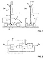
- the stabilization of the mast takes place by means of a control device, as is known to the person skilled in the art in the basic principle.
- a suitable control loop for a single degree of freedom is in the Fig. 2 exemplified.
- the actual orientation of the mast ⁇ M ie the tilt angle of the mast relative to the vertical about a given axis in the XY plane
- Both quantities are supplied to an electronic control device 10. In a unit ⁇ the difference of these quantities is formed and fed to a controller C.
- the actuator device forms part of a controlled system P, which acts as a disturbance variable, the inclination ⁇ V of the vehicle.
- the controlled system ultimately leads to a change in the controlled variable ⁇ M , which in turn is fed back to the control device 10.
- controller C any suitable controller, as is known from the prior art, are used, in the simplest case, for example, a P, PI, PD, or PID controller.
- the controller can be implemented in analog or digital electronics. He is preferably in digital electronics, whereby the measured quantities are converted into a binary format by suitable analog-digital converters (ADC).
- ADC analog-digital converters
- the controller may comprise a suitable digital signal processor or a general-purpose computer on which the actual control algorithm is implemented in software.
- the output of the manipulated variables, ie the actuation of the actuators can be done by suitable digital-to-analog converters (DAC) or by direct digital control types, such as pulse width modulation.
- DAC digital-to-analog converters
- a first embodiment with electrically driven cables is in the FIGS. 3 to 5 illustrated.
- at least one cable pull system 6 or 6 ' is present in the vehicle transverse direction and the vehicle longitudinal direction.
- Each of the two cable systems comprises two cable drives 61, 62.
- a pull cable 63 for example a steel cable, is tensioned, which is connected at an attachment point 64 to the telescopic mast 3, here with its lowermost section 31.
- the cable drives are designed in the present example as electric motor driven cable drums on which the opposite ends of the traction cable are wound.
- the length of a cable section 65 between the first Clamping device 61 and the attachment point 64 relative to the length of a second cable section 66 between the attachment point 64 and the second tensioning device 62 are changed, as shown in the Fig. 4 for movements about the vehicle longitudinal axis (rolling motions, referred to ships as rollers) is illustrated. In this way it can be achieved that the orientation of the mast is always stabilized independently of the orientation of the vehicle along the vertical.
- the endless traction cable which is also preferably designed as a steel cable, biased by a tensioning device and is driven with a single cable drive, as known from the prior art, along its longitudinal direction.
- a safety device 7 is proposed, which is basically similar to the cable systems 6, 6 'is constructed and in the Fig. 5 is shown.
- the securing device comprises a first tensioning device 71 and a second tensioning device 72.
- these are designed as rope drums preloaded with spiral springs.
- a safety cable 73 is tensioned, which is connected at an attachment point 74 with the telescopic mast 3, in the present example with its second section 32.
- the tensioners 71, 72 are biased to keep the safety cable 73 taut in any orientation that the mast assumes during normal operation.
- Each clamping device is equipped with a blocking device in the form of an electrically actuated coupling. In normal operation, this clutch is disengaged, and the safety cable 73 is thereby alstriebslos on changes in position of the mast 3 or unwound.
- an acceleration sensor Connected to the vehicle or to the mast is an acceleration sensor, not shown in the drawings, which measures its own acceleration in the longitudinal direction. If a predefined acceleration value is exceeded is, the couplings of the safety device are blocked, and at the same time intervenes in the control device 10 such that the actuators are dead, that is, the controller is stopped and its output is set to zero. In this way, the mast is held in the last available orientation relative to the vehicle. Only when the acceleration in the vehicle longitudinal direction again falls below a predetermined acceleration value, the clutches are disengaged again, and the control device 10 is activated again.
- the securing device can be designed differently than in the preceding embodiment.
- an arrangement with an endless, prestressed safety rope can also be used for the safety device, wherein the safety rope is guided substantially powerless in normal operation and is blocked when the predetermined acceleration value is exceeded with a locking device relative to the vehicle chassis.
- Also completely different than designed by cables securing devices are conceivable.
- such a securing device may be provided not only in the longitudinal direction but also in the transverse direction. It is also conceivable, e.g. to arrange two such security devices cross and diagonal to the vehicle chassis.
- suitable couplings can also be provided directly in the cable drives 61, 62 of the cable pull system 6 ', so that a separate cable pull system for the safety device can be dispensed with.
- this requires a more complex design of the cable system 6 '.
- the cable drives of the cable system or the blocking devices of the safety device are each connected to the vehicle chassis 21, it is also conceivable, the ropes 63 and / or 73 each with their ends on Fix vehicle chassis and arrange a suitable drive device or a blocking device according to the mast. However, it is preferable to arrange these devices as in the above embodiment stationary to the vehicle chassis in order to keep the weight carried by the mast as low as possible.
- FIGS. 6 to 8 A second embodiment of the actuator device is in the FIGS. 6 to 8 illustrated.
- two orthogonal arranged linear drives available, which can generate equal tensile and compressive forces.
- This type of technical design makes it particularly easier to arrange the mast in the rear of a vehicle, as is the case in the above-discussed embodiment with cables.
- the mast 3 ' in turn as a telescopic mast with a first portion 31', section 32 'and a third portion 33' is formed, which carries a payload 4 '.
- the mast is mounted in this example via a ball joint as a mast bearing 5 'on the chassis 21 of the vehicle 2.
- a support 84 Also connected to the chassis 21 is a support 84, on which a drive device 81 in the form of an electric motor with spindle drive is mounted via a pivotable bearing.
- the motor serves to drive a threaded spindle (threaded rod) 82 to rotate about its longitudinal axis.
- the threaded spindle 82 is connected to a threaded nut, which is located in the interior of the lowermost portion 31 'of the mast 3' and is rotatably held therein in a bearing 83.
- a threaded nut which is located in the interior of the lowermost portion 31 'of the mast 3' and is rotatably held therein in a bearing 83.
- the actuator device it may be useful to detect not only the position of the mast 3 with respect to the absolute vertical in space, but also the orientation of the vehicle 2 Vehicle 2 an optional further sensor device 22 may be present, as shown in the Fig. 1 is indicated. This detects the vehicle orientation relative to the vertical and leads them to the then designed accordingly controller C as a further input variable, as in the Fig. 2 indicated by the dashed arrow.
- the controller is enabled to bring the controlled variable faster and more stable to the reference variable than would be possible without knowing the position of the vehicle. This is particularly useful when the control has been interrupted for a certain time due to the intervention of a safety device, as described above by way of example.
Landscapes
- Forklifts And Lifting Vehicles (AREA)
Claims (15)
- Un système permettant la stabilisation d'un mât (3) sur un support mobile, comportant :un mât (3) définissant une direction longitudinale (34) ;un palier de mât (5), formé de sorte à articuler par pivotement le mât (3) autour au moins un axe de pivotement (X; Y) ;un dispositif actionneur (6, 6', 8, 8'), étant connecté au mât (3) et formé de sorte à pivoter le mât (3) avec sa direction longitudinale autour au moins un axe de pivotement (X; Y) par rapport au support (2);un dispositif de capteurs de mât (35), formé de sorte à déterminer la direction longitudinale (34) du mât (3) par rapport à une direction spatiale absolue prédéterminée ; ainsi queun dispositif de réglage (10), formé de sorte à recevoir des signaux sur la direction du dispositif de capteurs de mât (35), à comparer avec une valeur de consigne (θS) pour la direction longitudinale du mât et en dériver la grandeur de commande (µA) pour le dispositif de réglage, pour stabiliser la direction longitudinale du mât par rapport à la valeur de consigne (θS) ;caractérisé en ce que le système présente un dispositif d'arrêt (7) pour surveiller les valeurs de l'accélération du mât (3) et/ou du support (2) et pour bloquer le mât (3) lors du dépassement d'une valeur prédéterminée de l'accélération par rapport à un mouvement de pivotement.
- Système selon la revendication 1, caractérisé en ce que, le dispositif d'arrêt (7) est formé en système de tirage, qui comprend :- au moins un cordage d'arrêt (73) s'étendant entre le mât (3) et le support (2) et- au moins un dispositif de guidage de cordage (71,72) sur lequel le cordage d'arrêt (73) est guidé et qui bloque le cordage d'arrêt (73) lors du dépassement d'une valeur prédéterminé de l'accélération survenant au mât et/ou au support, de telle manière qu'un pivotement additionnel du mât (3) est évité.
- Le système selon la revendication 2, caractérisé en ce que le dispositif de guidage du cordage (71,72) présente au moins un tambour de cordage ayant un élément de ressort, que le tambour de cordage et formé de sorte à être connecté avec le support (2) et que le cordage d'arrêt (73) peut être sollicité par l'élément de ressort.
- Système selon les revendications 2 ou 3, dans lequel le dispositif de guidage de cordage (71,72) présente au moins un couplage mécanique ou électrique opérable pour bloquer le cordage d'arrêt (73).
- Système selon une des revendications 2 à 4, dans lequel le cordage d'arrêt (73) est connecté au mât au-dessus du palier de mât.
- Système selon une des revendications précédentes, caractérisé en ce que le palier de mât (5) est formé de sorte à permettre un mouvement du mât (3) autour de deux axes de pivotement (X,Y) orthogonaux l'un par rapport à l'autre, que le dispositif de capteur de mât (35) est formé de sorte à enregistrer la direction longitudinale du mât (3) par rapport au deux axes de pivotement (X; Y), et que le dispositif actionneur (6,6',8,8') est formé de sorte à pivoter le mât autour des deux axes de pivotement (X; Y).
- Système selon une des revendications précédentes, caractérisé en ce que le mât (3) est un mât télescopique ayant une pluralité de segments de mât (31,32,33) étants mobiles le long de la direction longitudinale l'un par rapport à l'autre.
- Système selon une des revendications précédentes, caractérisé en ce que le système comprend d'avantage un dispositif de capteur de support (22), formé de sorte à enregistrer l'orientation du support (2) par rapport à une direction spatiale prédéterminée, et que le dispositif de réglage (10) est formé de sorte à recevoir en outre des signaux d'orientation (θV) du dispositif de capteur de support (22) et à les prendre en compte lors de la détermination de la grandeur de commande (9a).
- Système selon une des revendications précédentes, caractérisé en ce que le dispositif actionneur (6,6') présente au moins un système de tirage qui comprend :- -au moins un cordage (63) s'étendant entre le mât (3) et le support (2) et- au moins un entraînement de cordage (61,62) formé de sorte à entraîner le cordage (63) d'une manière à ce que le mât (3) est pivoté avec sa direction longitudinale (34) relative au support (2).
- Système selon la revendication 9, caractérisé en ce que le dispositif d'arrêt (7) comprend un couplage pour l'entraînement de cordage (61,62), qui bloque le cordage 63) lors du dépassement d'une accélération prédéterminée.
- Système selon une des revendication 1 à 8, caractérisé en ce que le dispositif actionneur (8,8') présent au moins un entraînement par vis, qui comprend :- une vis fileté (82) ;- un écrou à vis ; et- un dispositif d'entrainement (81), formé de sorte à entraiîner en rotation relative la vis fileté (82) et l'écrou à vis, de sorte à ce que la rotation provoque un pivotement du mât (3) par rapport au support (2).
- Véhicule ayant monté sur lui un système selon une des revendications précédentes, dans lequel le véhicule sert de support (2) et définit une direction longitudinale du véhicule (X).
- Véhicule selon la revendication 12, dans lequel le dispositif d'arrêt (7) est formé de sorte à bloquer le mât (3) lors du dépassement d'une valeur prédéterminée d'accélération par rapport à des mouvements de pivotement en direction longitudinale du véhicule.
- Procédé pour la stabilisation d'un mât (3) sur un support mobile (2), dans lequel le procédé comprend :- articuler un mât (3) sur un support (2) à travers un palier de mât (5), de sorte à ce que le mât (3) est pivotable autour au moins un axe de pivotement (X,Y) par rapport au support (2) ;- déterminer la direction longitudinale (34) du mât (3) par rapport à une direction spatiale prédétermine absolue;- déterminer une grandeur de commande (9a) pour un dispositif actionneur (6;8) à travers un dispositif de réglage électronique couplé rétroactivement (10) qui présente comme grandeur d'entrée au moins la direction longitudinale (34) déterminée du mât (3) ainsi que une valeur de consigne (θS) prédéterminée pour la direction longitudinale du mât ;- pivoter le mât (3) à travers un dispositif actionneur (6;8), qui est connecté avec le mât (3) et reçoit la grandeur de commande (9a) du dispositif du réglage (10), pour stabiliser la direction longitudinale du mât (3) par rapport à la valeur de consigne (θS) ;- contrôler les valeurs d'accélération du mât (3) et ou du support (2) ; et- bloquer le mât (3) par rapport à un mouvement de pivotement lors du dépassement d'une valeur d'accélération prédéterminée.
- Procédé selon la revendication 14, qui comprend d'avantage :- intervenir dans le dispositif de réglage (10) lors du blocage du mât (3) de sorte à rendre le dispositif actionneur (6;8) débrayé.
Applications Claiming Priority (2)
| Application Number | Priority Date | Filing Date | Title |
|---|---|---|---|
| CH16092008 | 2008-10-10 | ||
| PCT/CH2009/000314 WO2010040237A1 (fr) | 2008-10-10 | 2009-10-02 | Stabilisation d’un mât pour des véhicules et des bateaux |
Publications (2)
| Publication Number | Publication Date |
|---|---|
| EP2332209A1 EP2332209A1 (fr) | 2011-06-15 |
| EP2332209B1 true EP2332209B1 (fr) | 2015-12-16 |
Family
ID=40445626
Family Applications (1)
| Application Number | Title | Priority Date | Filing Date |
|---|---|---|---|
| EP09736090.3A Not-in-force EP2332209B1 (fr) | 2008-10-10 | 2009-10-02 | Stabilisation d'un mât pour des véhicules et des bateaux |
Country Status (4)
| Country | Link |
|---|---|
| US (1) | US8494725B2 (fr) |
| EP (1) | EP2332209B1 (fr) |
| IL (1) | IL212063A0 (fr) |
| WO (1) | WO2010040237A1 (fr) |
Families Citing this family (10)
| Publication number | Priority date | Publication date | Assignee | Title |
|---|---|---|---|---|
| HUE036337T2 (hu) * | 2007-04-16 | 2018-07-30 | Drs Sustainment Systems Inc | Teleszkópos árboc |
| US20130208494A1 (en) * | 2012-02-14 | 2013-08-15 | Russell C. Jones | Emergency vehicle lighting apparatus including a light bar that can be raised to increase visibility during an emergency |
| US9450286B1 (en) * | 2012-09-12 | 2016-09-20 | Viasat, Inc. | Systems, devices, and methods for stabilizing an antenna |
| EP2712022A1 (fr) * | 2012-09-24 | 2014-03-26 | Oticon A/s | Dispositif de communication fixe doté d'une antenne |
| US9953464B2 (en) * | 2013-09-26 | 2018-04-24 | Conduent Business Services, Llc | Portable occupancy detection methods, systems and processor-readable media |
| US10283837B2 (en) | 2015-10-23 | 2019-05-07 | Viasat, Inc. | Apparatuses for mounting an antenna assembly |
| US10746349B2 (en) * | 2018-01-15 | 2020-08-18 | Hamaye Co | Extendable cage telescopic system |
| US10897070B2 (en) * | 2018-08-01 | 2021-01-19 | Wilson Electronics, Llc | Connect RV mount |
| US11358845B1 (en) * | 2019-03-15 | 2022-06-14 | Amazon Technologies, Inc. | Electromagnetic noise cancellation apparatus for cable deployed at varying length |
| DE102020109341B3 (de) | 2020-04-03 | 2021-07-01 | FoMa Systems GmbH | Stabilisierungsvorrichtung und Verfahren zur Stabilisierung eines Befestigungsbauteils |
Family Cites Families (10)
| Publication number | Priority date | Publication date | Assignee | Title |
|---|---|---|---|---|
| NL8204027A (nl) * | 1982-10-19 | 1984-05-16 | Hollandse Signaalapparaten Bv | Inrichting voor het stabiliseren van een, op een voer- of vaartuig aangebrachte rondzoekeenheid. |
| NL8400008A (nl) * | 1984-01-03 | 1985-08-01 | Hollandse Signaalapparaten Bv | Opstelling voor een rondzoekapparaat. |
| US4709265A (en) * | 1985-10-15 | 1987-11-24 | Advanced Resource Development Corporation | Remote control mobile surveillance system |
| DE4405644A1 (de) * | 1994-02-22 | 1994-10-06 | Rst Raumfahrt Systemtechnik Gm | Verfahren und Vorrichtung zur Ausrichtung und Stabilisierung von Antennen für Satellitendatenempfang |
| US5922039A (en) * | 1996-09-19 | 1999-07-13 | Astral, Inc. | Actively stabilized platform system |
| NL1006599C2 (nl) * | 1997-07-16 | 1999-01-19 | Hollandse Signaalapparaten Bv | Stelsel voor het stabiliseren van een op een beweegbaar platform geplaatst object. |
| WO2005053093A1 (fr) * | 2003-11-27 | 2005-06-09 | Wiworld Co., Ltd | Systeme d'antenne ameliore pour la poursuite de satellite monte sur un objet en mouvement et son mode de fonctionnement |
| FR2867615B1 (fr) * | 2004-03-12 | 2008-09-05 | Thales Sa | Dispositif elevateur pour tete senseur |
| US7959115B2 (en) * | 2006-09-07 | 2011-06-14 | Madsen Paul C | Versatile pole support, system and method |
| US20090244279A1 (en) * | 2008-03-26 | 2009-10-01 | Jeffrey Thomas Walsh | Surveillance systems |
-
2009
- 2009-10-02 WO PCT/CH2009/000314 patent/WO2010040237A1/fr active Application Filing
- 2009-10-02 US US13/123,361 patent/US8494725B2/en not_active Expired - Fee Related
- 2009-10-02 EP EP09736090.3A patent/EP2332209B1/fr not_active Not-in-force
-
2011
- 2011-03-31 IL IL212063A patent/IL212063A0/en not_active IP Right Cessation
Also Published As
| Publication number | Publication date |
|---|---|
| US8494725B2 (en) | 2013-07-23 |
| IL212063A0 (en) | 2011-06-30 |
| EP2332209A1 (fr) | 2011-06-15 |
| US20110196581A1 (en) | 2011-08-11 |
| WO2010040237A1 (fr) | 2010-04-15 |
Similar Documents
| Publication | Publication Date | Title |
|---|---|---|
| EP2332209B1 (fr) | Stabilisation d'un mât pour des véhicules et des bateaux | |
| EP3065530B1 (fr) | Dispositif pour distribuer des substances actives liquides et/ou solides et procédé de commande d'un tel dispositif | |
| DE102016102713B4 (de) | Nivellierungseinheit | |
| EP3035795B1 (fr) | Pulvérisateur pour épandre des substances actives liquides et/ou solides et contrôle d'un tel | |
| EP2591657B1 (fr) | Dispositif mobile destiné à sortir des agents actifs liquides et/ou solides et procédé de commande du dispositif | |
| DE102010023228B4 (de) | Stabilisierungseinrichtung | |
| EP2446505A1 (fr) | Support pour un capteur mobile | |
| EP3553021B1 (fr) | Réduction proactive des vibrations dans un chariot de manutention | |
| WO1983003815A1 (fr) | Dispositif de chargement pour charges mobiles relativement a un plan d'eau | |
| DE10257109B3 (de) | Regalbediengerät | |
| DE102013206696B4 (de) | Vorrichtung und ein Verfahren zur Steuerung einer Handhabungseinrichtung | |
| DE102020109341B3 (de) | Stabilisierungsvorrichtung und Verfahren zur Stabilisierung eines Befestigungsbauteils | |
| DE102017114478A1 (de) | Automatisches Lastpositionierungssystem für einen Hubschrauber mit einer Außenwinde | |
| DE102018106463B4 (de) | Verfahren zur automatischen Unterstützung des Landens eines Luftfahrzeuges, Computerprogramm und System dafür | |
| DE102017110006B4 (de) | Außenwinde für einen Hubschrauber mit Einrichtungen zur Stabilisierung einer an die Außenwinde angehängten Außenlast und Hubschrauber mit einer solchen Außenwinde | |
| EP3366432B1 (fr) | Système de mesure et dispositif de transport | |
| DE102018120579A1 (de) | Vorrichtung zum Anordnen eines Aufzugsystems und Verfahren zum Ausrichten der Vorrichtung | |
| DE102018106462B4 (de) | Verfahren zur automatischen Unterstützung des Landens eines Luftfahrzeuges, Computerprogramm und System dafür | |
| DE102016102540B3 (de) | Verfahren und Hubschrauber mit Einrichtungen zur Stabilisierung einer an eine Außenwinde angehängten Last | |
| EP2740706B1 (fr) | Dispositif de transport et procédé de transport | |
| WO2000073196A1 (fr) | Unite de blocage de charge | |
| DE2352725C2 (de) | Vorrichtung zur Sicherung eines Kranes gegen Überlastung | |
| AT511985B1 (de) | Transportvorrichtung und transportverfahren | |
| DE102018106729A1 (de) | Gefederte Hebevorrichtung für einen Kran | |
| DE19830746A1 (de) | Vorrichtung mit einem verfahrbaren Ausleger |
Legal Events
| Date | Code | Title | Description |
|---|---|---|---|
| PUAI | Public reference made under article 153(3) epc to a published international application that has entered the european phase |
Free format text: ORIGINAL CODE: 0009012 |
|
| 17P | Request for examination filed |
Effective date: 20110328 |
|
| AK | Designated contracting states |
Kind code of ref document: A1 Designated state(s): AT BE BG CH CY CZ DE DK EE ES FI FR GB GR HR HU IE IS IT LI LT LU LV MC MK MT NL NO PL PT RO SE SI SK SM TR |
|
| AX | Request for extension of the european patent |
Extension state: AL BA RS |
|
| DAX | Request for extension of the european patent (deleted) | ||
| GRAP | Despatch of communication of intention to grant a patent |
Free format text: ORIGINAL CODE: EPIDOSNIGR1 |
|
| INTG | Intention to grant announced |
Effective date: 20150702 |
|
| RIN1 | Information on inventor provided before grant (corrected) |
Inventor name: ZURFLUH, ERWIN ALEX |
|
| GRAS | Grant fee paid |
Free format text: ORIGINAL CODE: EPIDOSNIGR3 |
|
| GRAA | (expected) grant |
Free format text: ORIGINAL CODE: 0009210 |
|
| AK | Designated contracting states |
Kind code of ref document: B1 Designated state(s): AT BE BG CH CY CZ DE DK EE ES FI FR GB GR HR HU IE IS IT LI LT LU LV MC MK MT NL NO PL PT RO SE SI SK SM TR |
|
| REG | Reference to a national code |
Ref country code: GB Ref legal event code: FG4D Free format text: NOT ENGLISH |
|
| REG | Reference to a national code |
Ref country code: CH Ref legal event code: NV Representative=s name: ISLER AND PEDRAZZINI AG, CH Ref country code: CH Ref legal event code: EP |
|
| REG | Reference to a national code |
Ref country code: IE Ref legal event code: FG4D Free format text: LANGUAGE OF EP DOCUMENT: GERMAN |
|
| REG | Reference to a national code |
Ref country code: AT Ref legal event code: REF Ref document number: 765951 Country of ref document: AT Kind code of ref document: T Effective date: 20160115 |
|
| REG | Reference to a national code |
Ref country code: DE Ref legal event code: R096 Ref document number: 502009011927 Country of ref document: DE |
|
| REG | Reference to a national code |
Ref country code: NL Ref legal event code: FP |
|
| REG | Reference to a national code |
Ref country code: LT Ref legal event code: MG4D |
|
| PG25 | Lapsed in a contracting state [announced via postgrant information from national office to epo] |
Ref country code: LT Free format text: LAPSE BECAUSE OF FAILURE TO SUBMIT A TRANSLATION OF THE DESCRIPTION OR TO PAY THE FEE WITHIN THE PRESCRIBED TIME-LIMIT Effective date: 20151216 Ref country code: NO Free format text: LAPSE BECAUSE OF FAILURE TO SUBMIT A TRANSLATION OF THE DESCRIPTION OR TO PAY THE FEE WITHIN THE PRESCRIBED TIME-LIMIT Effective date: 20160316 Ref country code: HR Free format text: LAPSE BECAUSE OF FAILURE TO SUBMIT A TRANSLATION OF THE DESCRIPTION OR TO PAY THE FEE WITHIN THE PRESCRIBED TIME-LIMIT Effective date: 20151216 |
|
| PG25 | Lapsed in a contracting state [announced via postgrant information from national office to epo] |
Ref country code: GR Free format text: LAPSE BECAUSE OF FAILURE TO SUBMIT A TRANSLATION OF THE DESCRIPTION OR TO PAY THE FEE WITHIN THE PRESCRIBED TIME-LIMIT Effective date: 20160317 Ref country code: FI Free format text: LAPSE BECAUSE OF FAILURE TO SUBMIT A TRANSLATION OF THE DESCRIPTION OR TO PAY THE FEE WITHIN THE PRESCRIBED TIME-LIMIT Effective date: 20151216 Ref country code: SE Free format text: LAPSE BECAUSE OF FAILURE TO SUBMIT A TRANSLATION OF THE DESCRIPTION OR TO PAY THE FEE WITHIN THE PRESCRIBED TIME-LIMIT Effective date: 20151216 Ref country code: LV Free format text: LAPSE BECAUSE OF FAILURE TO SUBMIT A TRANSLATION OF THE DESCRIPTION OR TO PAY THE FEE WITHIN THE PRESCRIBED TIME-LIMIT Effective date: 20151216 |
|
| PG25 | Lapsed in a contracting state [announced via postgrant information from national office to epo] |
Ref country code: ES Free format text: LAPSE BECAUSE OF FAILURE TO SUBMIT A TRANSLATION OF THE DESCRIPTION OR TO PAY THE FEE WITHIN THE PRESCRIBED TIME-LIMIT Effective date: 20151216 Ref country code: IT Free format text: LAPSE BECAUSE OF FAILURE TO SUBMIT A TRANSLATION OF THE DESCRIPTION OR TO PAY THE FEE WITHIN THE PRESCRIBED TIME-LIMIT Effective date: 20151216 Ref country code: CZ Free format text: LAPSE BECAUSE OF FAILURE TO SUBMIT A TRANSLATION OF THE DESCRIPTION OR TO PAY THE FEE WITHIN THE PRESCRIBED TIME-LIMIT Effective date: 20151216 |
|
| PG25 | Lapsed in a contracting state [announced via postgrant information from national office to epo] |
Ref country code: RO Free format text: LAPSE BECAUSE OF FAILURE TO SUBMIT A TRANSLATION OF THE DESCRIPTION OR TO PAY THE FEE WITHIN THE PRESCRIBED TIME-LIMIT Effective date: 20151216 Ref country code: SM Free format text: LAPSE BECAUSE OF FAILURE TO SUBMIT A TRANSLATION OF THE DESCRIPTION OR TO PAY THE FEE WITHIN THE PRESCRIBED TIME-LIMIT Effective date: 20151216 Ref country code: IS Free format text: LAPSE BECAUSE OF FAILURE TO SUBMIT A TRANSLATION OF THE DESCRIPTION OR TO PAY THE FEE WITHIN THE PRESCRIBED TIME-LIMIT Effective date: 20160416 Ref country code: PT Free format text: LAPSE BECAUSE OF FAILURE TO SUBMIT A TRANSLATION OF THE DESCRIPTION OR TO PAY THE FEE WITHIN THE PRESCRIBED TIME-LIMIT Effective date: 20160418 Ref country code: EE Free format text: LAPSE BECAUSE OF FAILURE TO SUBMIT A TRANSLATION OF THE DESCRIPTION OR TO PAY THE FEE WITHIN THE PRESCRIBED TIME-LIMIT Effective date: 20151216 Ref country code: SK Free format text: LAPSE BECAUSE OF FAILURE TO SUBMIT A TRANSLATION OF THE DESCRIPTION OR TO PAY THE FEE WITHIN THE PRESCRIBED TIME-LIMIT Effective date: 20151216 |
|
| REG | Reference to a national code |
Ref country code: DE Ref legal event code: R097 Ref document number: 502009011927 Country of ref document: DE |
|
| REG | Reference to a national code |
Ref country code: FR Ref legal event code: PLFP Year of fee payment: 8 |
|
| PLBE | No opposition filed within time limit |
Free format text: ORIGINAL CODE: 0009261 |
|
| STAA | Information on the status of an ep patent application or granted ep patent |
Free format text: STATUS: NO OPPOSITION FILED WITHIN TIME LIMIT |
|
| PG25 | Lapsed in a contracting state [announced via postgrant information from national office to epo] |
Ref country code: PL Free format text: LAPSE BECAUSE OF FAILURE TO SUBMIT A TRANSLATION OF THE DESCRIPTION OR TO PAY THE FEE WITHIN THE PRESCRIBED TIME-LIMIT Effective date: 20151216 Ref country code: DK Free format text: LAPSE BECAUSE OF FAILURE TO SUBMIT A TRANSLATION OF THE DESCRIPTION OR TO PAY THE FEE WITHIN THE PRESCRIBED TIME-LIMIT Effective date: 20151216 |
|
| PGFP | Annual fee paid to national office [announced via postgrant information from national office to epo] |
Ref country code: IE Payment date: 20160923 Year of fee payment: 8 |
|
| 26N | No opposition filed |
Effective date: 20160919 |
|
| PG25 | Lapsed in a contracting state [announced via postgrant information from national office to epo] |
Ref country code: BE Free format text: LAPSE BECAUSE OF NON-PAYMENT OF DUE FEES Effective date: 20161031 Ref country code: SI Free format text: LAPSE BECAUSE OF FAILURE TO SUBMIT A TRANSLATION OF THE DESCRIPTION OR TO PAY THE FEE WITHIN THE PRESCRIBED TIME-LIMIT Effective date: 20151216 |
|
| PG25 | Lapsed in a contracting state [announced via postgrant information from national office to epo] |
Ref country code: LU Free format text: LAPSE BECAUSE OF NON-PAYMENT OF DUE FEES Effective date: 20161002 |
|
| REG | Reference to a national code |
Ref country code: FR Ref legal event code: PLFP Year of fee payment: 9 |
|
| REG | Reference to a national code |
Ref country code: BE Ref legal event code: MM Effective date: 20161031 |
|
| REG | Reference to a national code |
Ref country code: AT Ref legal event code: MM01 Ref document number: 765951 Country of ref document: AT Kind code of ref document: T Effective date: 20161002 |
|
| PG25 | Lapsed in a contracting state [announced via postgrant information from national office to epo] |
Ref country code: AT Free format text: LAPSE BECAUSE OF NON-PAYMENT OF DUE FEES Effective date: 20161002 |
|
| PGFP | Annual fee paid to national office [announced via postgrant information from national office to epo] |
Ref country code: DE Payment date: 20171019 Year of fee payment: 9 Ref country code: FR Payment date: 20171024 Year of fee payment: 9 |
|
| PGFP | Annual fee paid to national office [announced via postgrant information from national office to epo] |
Ref country code: NL Payment date: 20171019 Year of fee payment: 9 Ref country code: GB Payment date: 20171019 Year of fee payment: 9 |
|
| PG25 | Lapsed in a contracting state [announced via postgrant information from national office to epo] |
Ref country code: CY Free format text: LAPSE BECAUSE OF FAILURE TO SUBMIT A TRANSLATION OF THE DESCRIPTION OR TO PAY THE FEE WITHIN THE PRESCRIBED TIME-LIMIT Effective date: 20151216 Ref country code: HU Free format text: LAPSE BECAUSE OF FAILURE TO SUBMIT A TRANSLATION OF THE DESCRIPTION OR TO PAY THE FEE WITHIN THE PRESCRIBED TIME-LIMIT; INVALID AB INITIO Effective date: 20091002 |
|
| PG25 | Lapsed in a contracting state [announced via postgrant information from national office to epo] |
Ref country code: MT Free format text: LAPSE BECAUSE OF FAILURE TO SUBMIT A TRANSLATION OF THE DESCRIPTION OR TO PAY THE FEE WITHIN THE PRESCRIBED TIME-LIMIT Effective date: 20151216 Ref country code: MC Free format text: LAPSE BECAUSE OF FAILURE TO SUBMIT A TRANSLATION OF THE DESCRIPTION OR TO PAY THE FEE WITHIN THE PRESCRIBED TIME-LIMIT Effective date: 20151216 Ref country code: TR Free format text: LAPSE BECAUSE OF FAILURE TO SUBMIT A TRANSLATION OF THE DESCRIPTION OR TO PAY THE FEE WITHIN THE PRESCRIBED TIME-LIMIT Effective date: 20151216 Ref country code: MK Free format text: LAPSE BECAUSE OF FAILURE TO SUBMIT A TRANSLATION OF THE DESCRIPTION OR TO PAY THE FEE WITHIN THE PRESCRIBED TIME-LIMIT Effective date: 20151216 |
|
| REG | Reference to a national code |
Ref country code: IE Ref legal event code: MM4A |
|
| PG25 | Lapsed in a contracting state [announced via postgrant information from national office to epo] |
Ref country code: BG Free format text: LAPSE BECAUSE OF FAILURE TO SUBMIT A TRANSLATION OF THE DESCRIPTION OR TO PAY THE FEE WITHIN THE PRESCRIBED TIME-LIMIT Effective date: 20151216 |
|
| PG25 | Lapsed in a contracting state [announced via postgrant information from national office to epo] |
Ref country code: IE Free format text: LAPSE BECAUSE OF NON-PAYMENT OF DUE FEES Effective date: 20171002 |
|
| PGFP | Annual fee paid to national office [announced via postgrant information from national office to epo] |
Ref country code: CH Payment date: 20181011 Year of fee payment: 10 |
|
| REG | Reference to a national code |
Ref country code: DE Ref legal event code: R119 Ref document number: 502009011927 Country of ref document: DE |
|
| REG | Reference to a national code |
Ref country code: NL Ref legal event code: MM Effective date: 20181101 |
|
| GBPC | Gb: european patent ceased through non-payment of renewal fee |
Effective date: 20181002 |
|
| PG25 | Lapsed in a contracting state [announced via postgrant information from national office to epo] |
Ref country code: DE Free format text: LAPSE BECAUSE OF NON-PAYMENT OF DUE FEES Effective date: 20190501 Ref country code: NL Free format text: LAPSE BECAUSE OF NON-PAYMENT OF DUE FEES Effective date: 20181101 |
|
| PG25 | Lapsed in a contracting state [announced via postgrant information from national office to epo] |
Ref country code: FR Free format text: LAPSE BECAUSE OF NON-PAYMENT OF DUE FEES Effective date: 20181031 |
|
| PG25 | Lapsed in a contracting state [announced via postgrant information from national office to epo] |
Ref country code: GB Free format text: LAPSE BECAUSE OF NON-PAYMENT OF DUE FEES Effective date: 20181002 |
|
| REG | Reference to a national code |
Ref country code: CH Ref legal event code: PL |
|
| PG25 | Lapsed in a contracting state [announced via postgrant information from national office to epo] |
Ref country code: LI Free format text: LAPSE BECAUSE OF NON-PAYMENT OF DUE FEES Effective date: 20191031 Ref country code: CH Free format text: LAPSE BECAUSE OF NON-PAYMENT OF DUE FEES Effective date: 20191031 |