EP2332209B1 - Stabilization of a mast for vehicles and ships - Google Patents
Stabilization of a mast for vehicles and ships Download PDFInfo
- Publication number
- EP2332209B1 EP2332209B1 EP09736090.3A EP09736090A EP2332209B1 EP 2332209 B1 EP2332209 B1 EP 2332209B1 EP 09736090 A EP09736090 A EP 09736090A EP 2332209 B1 EP2332209 B1 EP 2332209B1
- Authority
- EP
- European Patent Office
- Prior art keywords
- mast
- carrier
- cable
- longitudinal direction
- vehicle
- Prior art date
- Legal status (The legal status is an assumption and is not a legal conclusion. Google has not performed a legal analysis and makes no representation as to the accuracy of the status listed.)
- Not-in-force
Links
- 230000006641 stabilisation Effects 0.000 title claims description 12
- 238000011105 stabilization Methods 0.000 title claims description 12
- 230000001133 acceleration Effects 0.000 claims description 26
- 230000033001 locomotion Effects 0.000 claims description 25
- 238000000034 method Methods 0.000 claims description 9
- 230000000903 blocking effect Effects 0.000 claims description 7
- 238000012544 monitoring process Methods 0.000 claims description 4
- 238000010586 diagram Methods 0.000 description 7
- 230000000087 stabilizing effect Effects 0.000 description 6
- 230000008859 change Effects 0.000 description 5
- 230000008878 coupling Effects 0.000 description 4
- 238000010168 coupling process Methods 0.000 description 4
- 238000005859 coupling reaction Methods 0.000 description 4
- 230000003287 optical effect Effects 0.000 description 4
- 238000004891 communication Methods 0.000 description 3
- 238000013461 design Methods 0.000 description 3
- 238000005096 rolling process Methods 0.000 description 3
- 229910000831 Steel Inorganic materials 0.000 description 2
- 238000010276 construction Methods 0.000 description 2
- 230000007246 mechanism Effects 0.000 description 2
- 239000010959 steel Substances 0.000 description 2
- 241000220010 Rhode Species 0.000 description 1
- 239000000969 carrier Substances 0.000 description 1
- 238000001514 detection method Methods 0.000 description 1
- 230000000694 effects Effects 0.000 description 1
- 239000000835 fiber Substances 0.000 description 1
- 238000012986 modification Methods 0.000 description 1
- 230000004048 modification Effects 0.000 description 1
- 230000008569 process Effects 0.000 description 1
- 230000007363 regulatory process Effects 0.000 description 1
- XLYOFNOQVPJJNP-UHFFFAOYSA-N water Substances O XLYOFNOQVPJJNP-UHFFFAOYSA-N 0.000 description 1
Images


Classifications
-
- H—ELECTRICITY
- H01—ELECTRIC ELEMENTS
- H01Q—ANTENNAS, i.e. RADIO AERIALS
- H01Q1/00—Details of, or arrangements associated with, antennas
- H01Q1/12—Supports; Mounting means
- H01Q1/18—Means for stabilising antennas on an unstable platform
-
- H—ELECTRICITY
- H01—ELECTRIC ELEMENTS
- H01Q—ANTENNAS, i.e. RADIO AERIALS
- H01Q1/00—Details of, or arrangements associated with, antennas
- H01Q1/08—Means for collapsing antennas or parts thereof
- H01Q1/10—Telescopic elements
-
- H—ELECTRICITY
- H01—ELECTRIC ELEMENTS
- H01Q—ANTENNAS, i.e. RADIO AERIALS
- H01Q1/00—Details of, or arrangements associated with, antennas
- H01Q1/12—Supports; Mounting means
- H01Q1/1235—Collapsible supports; Means for erecting a rigid antenna
-
- H—ELECTRICITY
- H01—ELECTRIC ELEMENTS
- H01Q—ANTENNAS, i.e. RADIO AERIALS
- H01Q1/00—Details of, or arrangements associated with, antennas
- H01Q1/27—Adaptation for use in or on movable bodies
- H01Q1/32—Adaptation for use in or on road or rail vehicles
- H01Q1/3208—Adaptation for use in or on road or rail vehicles characterised by the application wherein the antenna is used
- H01Q1/3216—Adaptation for use in or on road or rail vehicles characterised by the application wherein the antenna is used where the road or rail vehicle is only used as transportation means
-
- H—ELECTRICITY
- H01—ELECTRIC ELEMENTS
- H01Q—ANTENNAS, i.e. RADIO AERIALS
- H01Q1/00—Details of, or arrangements associated with, antennas
- H01Q1/27—Adaptation for use in or on movable bodies
- H01Q1/34—Adaptation for use in or on ships, submarines, buoys or torpedoes
Definitions
- the present invention relates to a system for stabilizing the alignment of a mast on a mobile support, e.g. a land vehicle or a ship, and a corresponding procedure.
- a mobile support e.g. a land vehicle or a ship
- Transportable, extendable telescopic masts for reconnaissance vehicles are known from the prior art, which make it possible to position a payload at a variable height above the vehicle.
- the payload can be a sensor head with various monitoring and communication devices, eg with a communication antenna, an antenna of a reconnaissance radar, one or more cameras etc.
- Such a mast is eg in the WO 2005/099029 specified.
- the carrier vehicle is stationary and stationary as long as the mast is extended.
- the mast is retracted and then folded away, for example, stowed on the roof of the carrier vehicle or sunk into a storage space of the carrier vehicle.
- a payload such as a radar antenna against the rolling and pitching movements of the ship.
- the payload is located on a movable platform, which is passive (eg by centrifugal forces) or actively stabilized by a corresponding control loop with sensors and actuators.
- a variety of mechanical arrangements have been proposed, such as in the US 5,922,039 or US 4,647,939 . Regulatory processes for the active stabilization of such a platform have been described, for example, in US Pat WO 99/04224 or the EP 0 107 232 proposed.
- the stabilized platform directly supports the payload.
- such arrangements are generally unsuitable for stabilizing a payload on a telescopic mast because of their weight and size.
- the safety device can be used to relieve the actuator device during rapid braking of the vehicle in the short term of the inertial forces caused thereby.
- the actuator device can thereby be optimized so that it can change the longitudinal direction of the mast sufficiently quickly to follow changes in orientation of the carrier, without the actuator must absorb all forces acting on the mast forces in all operating conditions.
- the securing device can be designed in particular as a cable pull system.
- This comprises at least one safety rope, which extends between the mast and the carrier and is preferably connected to the mast above the mast bearing, and at least one cable guide device on which the safety rope is guided and the rope when exceeding a predetermined acceleration value on the mast and / or occurs on the carrier, blocked in such a way that further pivoting of the mast is prevented.
- an electrically actuated clutch or a mechanical clutch can be used.
- the cable guide device then preferably has at least one cable drum with a spring element, wherein the cable drum is adapted to be connected to the carrier, and wherein the Rope can be prestressed by means of the spring element.
- the spring element may for example be a coil spring.
- the mast is stabilized not only about a single pivot axis, but about two preferably mutually orthogonal pivot axes.
- the mast bearing is designed such that it allows a pivoting movement of the mast about two mutually orthogonal pivot axes.
- the mast sensor device is designed to detect the longitudinal direction of the mast with respect to both pivot axes, and the actuator device is designed to pivot the mast about both pivot axes. Accordingly, the controller is then formed two-dimensionally, i. it receives a two-dimensional controlled variable and generates a two-dimensional control variable, or there are two one-dimensional controller.
- the mast bearing may in particular comprise a universal joint or a ball joint. Preferably, it is designed such that it blocks a rotation of the mast about its longitudinal direction.
- the mast is preferably a telescopic mast with a plurality of mast segments movable relative to each other along the longitudinal direction. Such masts are known in a variety of configurations of the prior art. The invention is also applicable to one-piece masts.
- the mast sensor device preferably comprises at least one gyroscope.
- This may be a mechanical gyroscope, an optical gyroscope or a vibrating gyroscope.
- the gyro is drift-compensated in a known manner.
- the system may comprise a carrier sensor device which is designed to detect the orientation of the carrier with respect to the predetermined spatial direction.
- the control device is then designed to additionally receive direction signals from the carrier sensor device and to take them into account when determining the manipulated variable.
- the actuator device has at least one cable pull system.
- This comprises a pull rope which extends between the mast and the support and is preferably connected to the mast above the mast bearing, and at least one cable drive adapted to drive the pull rope to move, thereby moving the mast with its longitudinal direction to pivot relative to the carrier.
- the securing device may comprise a coupling of the cable drive, which blocks the pull rope when a predetermined acceleration is exceeded.
- a separately formed safety device is present, as described above.
- the actuator device has at least one spindle drive.
- This comprises a threaded spindle and a drive device, which is designed to enable the threaded spindle and a threaded nut in a relative rotation to each other, wherein the rotation causes a pivoting of the mast relative to the carrier.
- the system according to the invention is used on a land vehicle or a ship as a carrier and is accordingly adapted in its dimensions and the nature of its construction to such an application specifically.
- the invention is also directed to a vehicle, in particular a land or water vehicle, with such a system.
- the vehicle usually defines a vehicle longitudinal direction by its main movement direction, and the securing device is then preferably designed to block the mast when a predetermined acceleration value is exceeded, at least with respect to pivoting movements in the vehicle longitudinal direction.
- a method for active stabilization of a mast in particular a telescopic mast, having the features of claim 14 is given.
- the blocking can be done with a safety device as described above or otherwise.
- a vehicle 2 is shown with a telescopic mast 3 mounted therein. Based on this figure, the basic structure of a stabilization system according to the invention and the directions used in this document are explained.
- the vehicle 2 defines with its chassis 21 a vehicle longitudinal axis, which is referred to as the X direction ( Fig. 1 (a) ).
- the vehicle transverse axis is referred to as the Y direction ( Fig. 1 (b) ).
- Perpendicular to these two directions runs the vehicle vertical axis, which is referred to as Z-direction.
- the X, Y and Z directions together form a vehicle-fixed coordinate system.
- the telescopic mast 3 is composed of several mast segments, in the present example, three mast segments 31, 32 and 33. Of course, depending on the construction of the telescopic mast more or less mast segments may be present (in practice usually four or more).
- the mast segments are displaceable against each other along a longitudinal axis 34.
- any mechanism can be used, as it is known from the prior art, for example a cable mechanism as in the already mentioned WO 2005/099029 or a suitable spindle drive.
- the uppermost, here third, mast segment 33 carries a payload 4.
- This may in particular be a communication antenna, a radar antenna, an optical sensor or any other type of payload, as is commonly used in reconnaissance vehicles on telescopic masts. It goes without saying that the present invention is not limited to a particular type of payload.
- the first, lowest pole segment 31 is held in a mast bearing 5, which is rigidly connected to the chassis 21 of the vehicle 2.
- the mast bearing 5 allows pivotal movements of the longitudinal axis 34 of the mast 3 both about the vehicle longitudinal axis X and about the vehicle transverse axis Y.
- the mast bearing for example. be designed as a universal joint or as a ball joint, as is well known from the prior art. If the mast bearing is designed as a ball joint, a torsional movement about the mast longitudinal direction 34 in the mast bearing is preferably blocked, e.g. by a driver, which engages in a corresponding groove in the lowermost pole segment 31.
- the attachment point of the mast to the vehicle is preferably as deep as possible and near the center of the vehicle. By changing the orientation of the vehicle, the lateral forces acting on the mast bearing are minimized.
- a mast sensor device 35 is provided, which in the present example is attached to the top end of the mast, but may also be attached to any other mast segment.
- the mast sensor device directly permits detection of the position of the mast relative to the gravitational field of the earth and is provided with a device for stabilizing a possibly occurring drift with respect to the measuring axes relative to the gravitational field.
- This sensor device may comprise, for example, a mechanical gyroscope system (gyroscope), as has long been known from the prior art.
- gyroscope mechanical gyroscope system
- optical gyroscopes which are likewise known from the prior art.
- Such optical gyros are often referred to as laser gyro and use, for example, ring lasers, in which an interference between two rotating light waves is observed with opposite directions of rotation.
- gyros are available, for example, from Honeywell International Inc. of Morristown, New Jersey, USA.
- fiber optic gyros such as those available under the type designation DSP-3000 from KVH Industries, Inc., Middletown, Rhode Iceland, USA.
- the mast sensor device may also comprise a so-called vibration gyro, in which a vibrating system is used and the effect of the Coriolis force on this oscillating system is measured during a movement of the mast sensor device.
- vibratory gyros have been known for a long time.
- the stabilization of the mast takes place by means of a control device, as is known to the person skilled in the art in the basic principle.
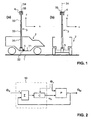
- a suitable control loop for a single degree of freedom is in the Fig. 2 exemplified.
- the actual orientation of the mast ⁇ M ie the tilt angle of the mast relative to the vertical about a given axis in the XY plane
- Both quantities are supplied to an electronic control device 10. In a unit ⁇ the difference of these quantities is formed and fed to a controller C.
- the actuator device forms part of a controlled system P, which acts as a disturbance variable, the inclination ⁇ V of the vehicle.
- the controlled system ultimately leads to a change in the controlled variable ⁇ M , which in turn is fed back to the control device 10.
- controller C any suitable controller, as is known from the prior art, are used, in the simplest case, for example, a P, PI, PD, or PID controller.
- the controller can be implemented in analog or digital electronics. He is preferably in digital electronics, whereby the measured quantities are converted into a binary format by suitable analog-digital converters (ADC).
- ADC analog-digital converters
- the controller may comprise a suitable digital signal processor or a general-purpose computer on which the actual control algorithm is implemented in software.
- the output of the manipulated variables, ie the actuation of the actuators can be done by suitable digital-to-analog converters (DAC) or by direct digital control types, such as pulse width modulation.
- DAC digital-to-analog converters
- a first embodiment with electrically driven cables is in the FIGS. 3 to 5 illustrated.
- at least one cable pull system 6 or 6 ' is present in the vehicle transverse direction and the vehicle longitudinal direction.
- Each of the two cable systems comprises two cable drives 61, 62.
- a pull cable 63 for example a steel cable, is tensioned, which is connected at an attachment point 64 to the telescopic mast 3, here with its lowermost section 31.
- the cable drives are designed in the present example as electric motor driven cable drums on which the opposite ends of the traction cable are wound.
- the length of a cable section 65 between the first Clamping device 61 and the attachment point 64 relative to the length of a second cable section 66 between the attachment point 64 and the second tensioning device 62 are changed, as shown in the Fig. 4 for movements about the vehicle longitudinal axis (rolling motions, referred to ships as rollers) is illustrated. In this way it can be achieved that the orientation of the mast is always stabilized independently of the orientation of the vehicle along the vertical.
- the endless traction cable which is also preferably designed as a steel cable, biased by a tensioning device and is driven with a single cable drive, as known from the prior art, along its longitudinal direction.
- a safety device 7 is proposed, which is basically similar to the cable systems 6, 6 'is constructed and in the Fig. 5 is shown.
- the securing device comprises a first tensioning device 71 and a second tensioning device 72.
- these are designed as rope drums preloaded with spiral springs.
- a safety cable 73 is tensioned, which is connected at an attachment point 74 with the telescopic mast 3, in the present example with its second section 32.
- the tensioners 71, 72 are biased to keep the safety cable 73 taut in any orientation that the mast assumes during normal operation.
- Each clamping device is equipped with a blocking device in the form of an electrically actuated coupling. In normal operation, this clutch is disengaged, and the safety cable 73 is thereby alstriebslos on changes in position of the mast 3 or unwound.
- an acceleration sensor Connected to the vehicle or to the mast is an acceleration sensor, not shown in the drawings, which measures its own acceleration in the longitudinal direction. If a predefined acceleration value is exceeded is, the couplings of the safety device are blocked, and at the same time intervenes in the control device 10 such that the actuators are dead, that is, the controller is stopped and its output is set to zero. In this way, the mast is held in the last available orientation relative to the vehicle. Only when the acceleration in the vehicle longitudinal direction again falls below a predetermined acceleration value, the clutches are disengaged again, and the control device 10 is activated again.
- the securing device can be designed differently than in the preceding embodiment.
- an arrangement with an endless, prestressed safety rope can also be used for the safety device, wherein the safety rope is guided substantially powerless in normal operation and is blocked when the predetermined acceleration value is exceeded with a locking device relative to the vehicle chassis.
- Also completely different than designed by cables securing devices are conceivable.
- such a securing device may be provided not only in the longitudinal direction but also in the transverse direction. It is also conceivable, e.g. to arrange two such security devices cross and diagonal to the vehicle chassis.
- suitable couplings can also be provided directly in the cable drives 61, 62 of the cable pull system 6 ', so that a separate cable pull system for the safety device can be dispensed with.
- this requires a more complex design of the cable system 6 '.
- the cable drives of the cable system or the blocking devices of the safety device are each connected to the vehicle chassis 21, it is also conceivable, the ropes 63 and / or 73 each with their ends on Fix vehicle chassis and arrange a suitable drive device or a blocking device according to the mast. However, it is preferable to arrange these devices as in the above embodiment stationary to the vehicle chassis in order to keep the weight carried by the mast as low as possible.
- FIGS. 6 to 8 A second embodiment of the actuator device is in the FIGS. 6 to 8 illustrated.
- two orthogonal arranged linear drives available, which can generate equal tensile and compressive forces.
- This type of technical design makes it particularly easier to arrange the mast in the rear of a vehicle, as is the case in the above-discussed embodiment with cables.
- the mast 3 ' in turn as a telescopic mast with a first portion 31', section 32 'and a third portion 33' is formed, which carries a payload 4 '.
- the mast is mounted in this example via a ball joint as a mast bearing 5 'on the chassis 21 of the vehicle 2.
- a support 84 Also connected to the chassis 21 is a support 84, on which a drive device 81 in the form of an electric motor with spindle drive is mounted via a pivotable bearing.
- the motor serves to drive a threaded spindle (threaded rod) 82 to rotate about its longitudinal axis.
- the threaded spindle 82 is connected to a threaded nut, which is located in the interior of the lowermost portion 31 'of the mast 3' and is rotatably held therein in a bearing 83.
- a threaded nut which is located in the interior of the lowermost portion 31 'of the mast 3' and is rotatably held therein in a bearing 83.
- the actuator device it may be useful to detect not only the position of the mast 3 with respect to the absolute vertical in space, but also the orientation of the vehicle 2 Vehicle 2 an optional further sensor device 22 may be present, as shown in the Fig. 1 is indicated. This detects the vehicle orientation relative to the vertical and leads them to the then designed accordingly controller C as a further input variable, as in the Fig. 2 indicated by the dashed arrow.
- the controller is enabled to bring the controlled variable faster and more stable to the reference variable than would be possible without knowing the position of the vehicle. This is particularly useful when the control has been interrupted for a certain time due to the intervention of a safety device, as described above by way of example.
Description
Die vorliegende Erfindung betrifft ein System zur Stabilisierung der Ausrichtung eines Mastes auf einem beweglichen Träger, z.B. einem Landfahrzeug oder einem Schiff, sowie ein entsprechendes Verfahren.The present invention relates to a system for stabilizing the alignment of a mast on a mobile support, e.g. a land vehicle or a ship, and a corresponding procedure.
Aus dem Stand der Technik sind transportable, ausfahrbare Teleskopmasten für Aufklärungsfahrzeuge bekannt, die es erlauben, eine Nutzlast in variabler Höhe über dem Fahrzeug zu positionieren. Bei der Nutzlast kann es sich insbesondere um einen Sensorkopf mit verschiedenen Überwachungs- und Kommunikationseinrichtungen handeln, z.B. mit einer Kommunikationsantenne, einer Antenne eines Aufklärungsradars, einer oder mehreren Kameras usw. Ein solcher Mast ist z.B. in der
Normalerweise ist das Trägerfahrzeug stationär und unbeweglich, solange der Mast ausgefahren ist. Bevor das Trägerfahrzeug bewegt wird, wird der Mast eingefahren und anschliessend z.B. abgeklappt auf dem Dach des Trägerfahrzeugs verstaut oder in einen Stauraum des Trägerfahrzeugs versenkt. Es kann jedoch in bestimmten Anwendungen erwünscht sein, das Trägerfahrzeug auch bei ausgefahrenem Mast zu bewegen und dabei die volle Funktionalität des Sensorkopfes zu erhalten. Dazu ist es nötig, die räumliche Orientierung des Sensorkopfes, insbesondere seine Lage relativ zur Vertikalen, trotz der Fahrzeugbewegungen stabil zu halten. Ähnliche Aufgaben stellen sich auch auf nicht landgebundenen Fahrzeugen, insbesondere Schiffen.Normally, the carrier vehicle is stationary and stationary as long as the mast is extended. Before the carrier vehicle is moved, the mast is retracted and then folded away, for example, stowed on the roof of the carrier vehicle or sunk into a storage space of the carrier vehicle. However, it may be desirable in certain applications to move the carrier vehicle even with the mast extended, thereby maintaining the full functionality of the sensor head. For this purpose, it is necessary to keep the spatial orientation of the sensor head, in particular its position relative to the vertical, in spite of the vehicle movements stable. Similar tasks also arise on non-land-based vehicles, in particular ships.
Aus der Schifffahrt ist es bekannt, eine Nutzlast wie z.B. eine Radarantenne gegenüber den Roll- und Stampfbewegungen des Schiffs aktiv zu stabilisieren. Die Nutzlast befindet sich dazu auf einer beweglichen Plattform, die passiv (z.B. durch Kreiselkräfte) oder aktiv durch einen entsprechenden Regelkreis mit Sensoren und Aktuatoren stabilisiert ist. Hierzu wurden verschiedenste mechanische Anordnungen vorgeschlagen, so z.B. in der
Aus der
Es ist daher eine Aufgabe der vorliegenden Erfindung, eine Vorrichtung anzugeben, die es ermöglicht, die Ausrichtung eines Mastes zu stabilisieren, wenn sich der Mast auf einem beweglichen Träger befindet und dadurch Bewegungen mit erheblichen Beschleunigungswerten unterworfen ist.It is therefore an object of the present invention to provide a device which makes it possible to stabilize the alignment of a mast when the mast is on a mobile support and thereby subjected to movements with significant acceleration values.
Diese Aufgabe wird durch eine Vorrichtung nach Anspruch 1 gelöst.This object is achieved by a device according to
Die vorliegende Erfindung schlägt also ein System zur Stabilisierung eines Mastes auf einem beweglichen Träger vor, mit den folgenden Merkmalen:
- einen eine Längsrichtung definierenden Mast;
- ein Mastlager, das dazu ausgebildet ist, den Mast um mindestens eine Schwenkachse schwenkbar auf dem Träger zu lagern;
- eine Aktuatoreinrichtung, die mit dem Mast verbunden ist und dazu ausgebildet ist, den Mast mit seiner Längsrichtung relativ zum Träger um die mindestens eine Schwenkachse zu verschwenken;
- eine Mastsensoreinrichtung, welche dazu ausgebildet ist, die Längsrichtung des Mastes relativ zu einer vorgegebenen absoluten Raumrichtung zu bestimmen;
- eine elektronische Regeleinrichtung, die dazu ausgebildet ist, Richtungssignale von der Mastsensoreinrichtung zu empfangen, mit einem vorgegebenen Sollwert für die Längsrichtung des Mastes zu vergleichen und daraus eine Stellgrösse für die Aktuatoreinrichtung abzuleiten, um die Längsrichtung des Mastes bezüglich des Sollwerts zu stabilisieren; sowie
- eine Sicherungseinrichtung, um Beschleunigungswerte des Mastes und/oder des Trägers zu überwachen und den Mast bei Überschreiten eines vorbestimmten Beschleunigungswerts bezüglich Schwenkbewegungen zu blockieren.
- a mast defining a longitudinal direction;
- a mast bearing adapted to pivotally mount the mast on the support about at least one pivot axis;
- an actuator device, which is connected to the mast and is adapted to the mast with its longitudinal direction relative to the carrier about the at least one Swivel pivot axis;
- a mast sensor device which is designed to determine the longitudinal direction of the mast relative to a predetermined absolute spatial direction;
- an electronic control device adapted to receive directional signals from the mast sensor device, to compare with a predetermined setpoint for the longitudinal direction of the mast and to derive therefrom a manipulated variable for the actuator device in order to stabilize the longitudinal direction of the mast with respect to the setpoint; such as
- a safety device to monitor acceleration values of the mast and / or the carrier and to block the mast when a predetermined acceleration value with respect to pivoting movements is exceeded.
Dadurch wird es möglich, den Mast zu sichern und dadurch die Aktuatoreinrichtung zu entlasten, wenn der Träger und dadurch auch der Mast sehr schnelle Bewegungsänderungen und damit einhergehende hohe Beschleunigungswerte erfährt. Wenn es sich beim Träger z.B. um ein Landfahrzeug handelt, kann die Sicherungseinrichtung dazu eingesetzt werden, die Aktuatoreinrichtung beim schnellen Bremsen des Fahrzeugs kurzfristig von den dadurch bewirkten Trägheitskräften zu entlasten. Die Aktuatoreinrichtung kann dadurch dahingehend optimiert werden, dass sie die Längsrichtung des Mastes genügend schnell verändern kann, um Orientierungsänderungen des Trägers zu folgen, ohne dass die Aktuatoreinrichtung in allen Betriebszuständen sämtliche auf den Mast wirkenden Kräfte aufnehmen muss.This makes it possible to secure the mast and thereby relieve the actuator device when the carrier and thereby also the mast experiences very rapid changes in movement and concomitant high acceleration values. If the carrier is e.g. is a land vehicle, the safety device can be used to relieve the actuator device during rapid braking of the vehicle in the short term of the inertial forces caused thereby. The actuator device can thereby be optimized so that it can change the longitudinal direction of the mast sufficiently quickly to follow changes in orientation of the carrier, without the actuator must absorb all forces acting on the mast forces in all operating conditions.
Die Sicherungseinrichtung kann insbesondere als Seilzugsystem ausgebildet sein. Dieses umfasst mindestens ein Sicherungsseil, das sich zwischen dem Mast und dem Träger erstreckt und vorzugsweise oberhalb des Mastlagers mit dem Mast verbunden ist, und mindestens eine Seilführungseinrichtung, auf der das Sicherungsseil geführt ist und die das Seil bei Überschreiten eines vorbestimmten Beschleunigungswerts, der am Mast und/oder am Träger auftritt, derart blockiert, dass ein weiteres Verschwenken des Mastes verhindert wird. Hierzu kann insbesondere eine elektrisch betätigbare Kupplung oder eine mechanische Kupplung zum Einsatz kommen. Die Seilführungseinrichtung weist dann vorzugsweise mindestens eine Seiltrommel mit einem Federelement auf, wobei die Seiltrommel dazu ausgebildet ist, mit dem Träger verbunden zu werden, und wobei das Seil mittels des Federelements vorspannbar ist. Das Federelement kann z.B. eine Spiralfeder sein.The securing device can be designed in particular as a cable pull system. This comprises at least one safety rope, which extends between the mast and the carrier and is preferably connected to the mast above the mast bearing, and at least one cable guide device on which the safety rope is guided and the rope when exceeding a predetermined acceleration value on the mast and / or occurs on the carrier, blocked in such a way that further pivoting of the mast is prevented. For this purpose, in particular an electrically actuated clutch or a mechanical clutch can be used. The cable guide device then preferably has at least one cable drum with a spring element, wherein the cable drum is adapted to be connected to the carrier, and wherein the Rope can be prestressed by means of the spring element. The spring element may for example be a coil spring.
Bevorzugt wird in dieser Vorrichtung bzw. diesem Verfahren der Mast nicht nur um eine einzige Schwenkachse, sondern um zwei vorzugsweise zueinander orthogonale Schwenkachsen stabilisiert. Dazu ist das Mastlager derart ausgebildet, dass es eine Schwenkbewegung des Mastes um zwei zueinander orthogonale Schwenkachsen erlaubt. Die Mastsensoreinrichtung ist dazu ausgebildet, die Längsrichtung des Mastes bezüglich beider Schwenkachsen zu erfassen, und die Aktuatoreinrichtung ist dazu ausgebildet, den Mast um beide Schwenkachsen zu verschwenken. Dementsprechend ist der Regler dann zweidimensional ausgebildet, d.h. er empfängt eine zweidimensionale Regelgrösse und erzeugt eine zweidimensionale Stellgrösse, oder es sind zwei eindimensionale Regler vorhanden.Preferably, in this device or this method, the mast is stabilized not only about a single pivot axis, but about two preferably mutually orthogonal pivot axes. For this purpose, the mast bearing is designed such that it allows a pivoting movement of the mast about two mutually orthogonal pivot axes. The mast sensor device is designed to detect the longitudinal direction of the mast with respect to both pivot axes, and the actuator device is designed to pivot the mast about both pivot axes. Accordingly, the controller is then formed two-dimensionally, i. it receives a two-dimensional controlled variable and generates a two-dimensional control variable, or there are two one-dimensional controller.
Das Mastlager kann insbesondere ein Kardangelenk oder ein Kugelgelenk umfassen. Bevorzugt ist es derart ausgestaltet, dass es eine Drehung des Mastes um seine Längsrichtung blockiert. Der Mast ist vorzugsweise ein Teleskopmast mit einer Mehrzahl von gegeneinander entlang der Längsrichtung beweglichen Mastsegmenten. Derartige Masten sind in einer Vielzahl von Ausgestaltungen aus dem Stand der Technik bekannt. Die Erfindung ist aber auch auf einteilige Masten anwendbar.The mast bearing may in particular comprise a universal joint or a ball joint. Preferably, it is designed such that it blocks a rotation of the mast about its longitudinal direction. The mast is preferably a telescopic mast with a plurality of mast segments movable relative to each other along the longitudinal direction. Such masts are known in a variety of configurations of the prior art. The invention is also applicable to one-piece masts.
Die Mastsensoreinrichtung umfasst bevorzugt mindestens einen Kreisel (Gyroskop). Dabei kann es sich um einen mechanischen Kreisel, einen optischen Kreisel oder einen Vibrationskreisel handeln. Vorzugsweise ist der Kreisel in bekannter Weise driftkompensiert.The mast sensor device preferably comprises at least one gyroscope. This may be a mechanical gyroscope, an optical gyroscope or a vibrating gyroscope. Preferably, the gyro is drift-compensated in a known manner.
Zusätzlich kann das System eine Trägersensoreinrichtung umfassen, welche dazu ausgebildet ist, die Ausrichtung des Trägers bezüglich der vorgegebenen Raumrichtung zu erfassen. Die Regeleinrichtung ist dann dazu ausgebildet, zusätzlich Richtungssignale von der Trägersensoreinrichtung zu empfangen und bei der Bestimmung der Stellgrösse zu berücksichtigen. Hierdurch kann eine schnellere und/oder stabilere Regelung erreicht werden, insbesondere nach Unterbrechungen der Regelung.In addition, the system may comprise a carrier sensor device which is designed to detect the orientation of the carrier with respect to the predetermined spatial direction. The control device is then designed to additionally receive direction signals from the carrier sensor device and to take them into account when determining the manipulated variable. As a result, a faster and / or more stable control can be achieved, in particular after interruptions of the control.
In einer ersten möglichen Ausführungsform weist die Aktuatoreinrichtung mindestens ein Seilzugsystem auf. Dieses umfasst ein Zugseil, das sich zwischen dem Mast und dem Träger erstreckt und dazu vorzugsweise oberhalb des Mastlagers mit dem Mast verbunden ist, und mindestens einen Seilantrieb, der dazu ausgebildet ist, das Zugseil zu einer Bewegung anzutreiben, um dadurch den Mast mit seiner Längsrichtung relativ zum Träger zu verschwenken.In a first possible embodiment, the actuator device has at least one cable pull system. This comprises a pull rope which extends between the mast and the support and is preferably connected to the mast above the mast bearing, and at least one cable drive adapted to drive the pull rope to move, thereby moving the mast with its longitudinal direction to pivot relative to the carrier.
Die Sicherungseinrichtung kann dabei eine Kupplung des Seilantriebs umfassen, welche das Zugseil bei Überschreiten einer vorgegebenen Beschleunigung blockiert. Vorzugsweise ist aber eine getrennt ausgebildete Sicherungseinrichtung vorhanden, wie sie vorstehend beschrieben wurde.The securing device may comprise a coupling of the cable drive, which blocks the pull rope when a predetermined acceleration is exceeded. Preferably, however, a separately formed safety device is present, as described above.
Gemäss einer zweiten möglichen Ausführungsform weist die Aktuatoreinrichtung mindestens einen Spindelantrieb auf. Dieser umfasst eine Gewindespindel und eine Antriebseinrichtung, die dazu ausgebildet ist, die Gewindespindel und eine Gewindemutter in eine relative Drehung zueinander zu versetzen, wobei die Drehung ein Verschwenken des Mastes relativ zum Träger bewirkt.According to a second possible embodiment, the actuator device has at least one spindle drive. This comprises a threaded spindle and a drive device, which is designed to enable the threaded spindle and a threaded nut in a relative rotation to each other, wherein the rotation causes a pivoting of the mast relative to the carrier.
Vorzugsweise wird das erfindungsgemässe System auf einem Landfahrzeug oder einem Schiff als Träger eingesetzt und ist entsprechend in seinen Dimensionen und der Art seines Aufbaus an einen solchen Einsatzzweck spezifisch angepasst. Dementsprechend richtet sich die Erfindung auch auf ein Fahrzeug, insbesondere ein Land- oder Wasserfahrzeug, mit einem solchen System. Das Fahrzeug definiert üblicherweise durch seine Hauptbewegungsrichtung eine Fahrzeuglängsrichtung, und die Sicherungseinrichtung ist dann vorzugsweise dazu ausgebildet, den Mast bei Überschreiten eines vorbestimmten Beschleunigungswerts zumindest bezüglich Schwenkbewegungen in der Fahrzeuglängsrichtung zu blockieren.Preferably, the system according to the invention is used on a land vehicle or a ship as a carrier and is accordingly adapted in its dimensions and the nature of its construction to such an application specifically. Accordingly, the invention is also directed to a vehicle, in particular a land or water vehicle, with such a system. The vehicle usually defines a vehicle longitudinal direction by its main movement direction, and the securing device is then preferably designed to block the mast when a predetermined acceleration value is exceeded, at least with respect to pivoting movements in the vehicle longitudinal direction.
Gemäss einem weiteren Aspekt der Erfindung wird ein Verfahren zur aktiven Stabilisierung eines Mastes, insbesondere eines Teleskopmastes, mit den Merkmalen des Anspruchs 14 angegeben.According to a further aspect of the invention, a method for active stabilization of a mast, in particular a telescopic mast, having the features of
Ein erfindungsgemässes Verfahren umfasst insbesondere die folgenden Schritte:
- Lagern des Mastes auf dem Träger mittels eines Mastlagers, so dass der Mast um mindestens eine Schwenkachse gegenüber dem Träger schwenkbar ist;
- Ermitteln der Längsrichtung des Mastes relativ zu einer vorgegebenen absoluten Raumrichtung;
- Bestimmen einer Stellgrösse für eine Aktuatoreinrichtung mittels einer rückgekoppelten elektronischen Regeleinrichtung, welche als Eingangsgrössen mindestens die ermittelte Längsrichtung des Mastes sowie einen vorgegebenen Sollwert für die Längsrichtung des Mastes aufweist;
- Verschwenken des Mastes mittels einer Aktuatoreinrichtung, die mit dem Mast verbunden ist und die Stellgrösse von der Regeleinrichtung empfängt, um die Längsrichtung des Mastes relativ zum Sollwert zu stabilisieren;
- Überwachen von Beschleunigungswerte des Mastes und/oder des Trägers;
- Blockieren des Mastes bezüglich seiner Schwenkbewegungen bei Überschreiten eines vorbestimmten Beschleunigungswerts.
- Bearing the mast on the support by means of a mast bearing, so that the mast is pivotable about at least one pivot axis relative to the carrier;
- Determining the longitudinal direction of the mast relative to a predetermined absolute spatial direction;
- Determining a manipulated variable for an actuator device by means of a feedback electronic control device, which has as input variables at least the determined longitudinal direction of the mast and a predetermined desired value for the longitudinal direction of the mast;
- Pivoting the mast by means of actuator means connected to the mast and receiving the manipulated variable from the control means to stabilize the longitudinal direction of the mast relative to the target value;
- Monitoring acceleration values of the mast and / or the carrier;
- Blocking of the mast with respect to its pivotal movements when exceeding a predetermined acceleration value.
Das Blockieren kann mit einer Sicherungseinrichtung wie vorstehend beschrieben oder auf andere Weise erfolgen.The blocking can be done with a safety device as described above or otherwise.
Bevorzugte Ausführungsformen der Erfindung werden im Folgenden anhand der Zeichnungen beschrieben, in denen zeigen:
- Fig. 1
- eine stark schematische Prinzipskizze eines Fahrzeugs mit darin angebrachtem Teleskopmast zur Illustration der in diesem Dokument verwendeten Richtungsangaben;
- Fig. 2
- eine schematische Darstellung einer Regeleinrichtung für die Stabilisierung eines Mastes;
- Fig. 3
- eine stark schematische Prinzipskizze eines Fahrzeugs mit darin angebrachtem, stabilisiertem Teleskopmast in einer eingefahrenen Stellung (Teilansicht (a)) und einer ausgefahrenen Stellung (Teilansicht (b)) gemäss einer ersten Ausführungsform;
- Fig. 4
- eine stark schematische Prinzipskizze des Fahrzeugs der
Fig. 3 zur Illustration der Stabilisierung des Teleskopmastes gegenüber Bewegungen um die Längsachse (Wankbewegungen); - Fig. 5
- eine stark schematische Prinzipskizze des Fahrzeugs der
Fig. 3 zur Illustration der Stabilisierung des Teleskopmastes gegenüber Bewegungen um die Querachse (Nickbewegungen); - Fig. 6
- eine stark schematische Prinzipskizze einer Stabilisierungseinrichtung für einen Teleskopmast gemäss einer zweiten Ausführungsform;
- Fig. 7
- eine stark schematische Prinzipskizze einer möglichen Anordnung einer derartigen Stabilisierungseinrichtung in einem Fahrzeug; sowie
- Fig. 8
- eine stark schematische Prinzipskizze zur Illustration der Funktionsweise der Stabilisierungseinrichtung gemäss der zweiten Ausführungsform.
- Fig. 1
- a highly schematic schematic diagram of a vehicle with attached telescopic mast to illustrate the directional information used in this document;
- Fig. 2
- a schematic representation of a control device for the stabilization of a mast;
- Fig. 3
- a highly schematic schematic diagram of a vehicle with it mounted, stabilized telescopic mast in a retracted position (partial view (a)) and an extended position (partial view (b)) according to a first embodiment;
- Fig. 4
- a highly schematic schematic diagram of the vehicle
Fig. 3 to Illustration of the stabilization of the telescopic mast with respect to movements about the longitudinal axis (rolling motions); - Fig. 5
- a highly schematic schematic diagram of the vehicle
Fig. 3 to illustrate the stabilization of the telescopic mast against movements about the transverse axis (pitching movements); - Fig. 6
- a highly schematic schematic diagram of a stabilizing device for a telescopic mast according to a second embodiment;
- Fig. 7
- a highly schematic schematic diagram of a possible arrangement of such a stabilization device in a vehicle; such as
- Fig. 8
- a highly schematic schematic diagram illustrating the operation of the stabilizing device according to the second embodiment.
In der
Das Fahrzeug 2 definiert mit seinem Chassis 21 eine Fahrzeuglängsachse, die als X-Richtung bezeichnet wird (
Der Teleskopmast 3 ist aus mehreren Mastsegmenten aufgebaut, im vorliegenden Beispiel drei Mastsegmenten 31, 32 und 33. Selbstverständlich können je nach Konstruktion des Teleskopmastes auch mehr oder weniger Mastsegmente vorhanden sein (in der Praxis meist vier oder mehr). Die Mastsegmente sind entlang einer Längsachse 34 gegeneinander verschiebbar. Hierzu kann ein beliebiger Mechanismus eingesetzt werden, wie er aus dem Stand der Technik bekannt ist, z.B. ein Seilzugmechanismus wie in der schon erwähnten
Das oberste, hier dritte, Mastsegment 33 trägt eine Nutzlast 4. Bei dieser kann es sich insbesondere um eine Kommunikationsantenne, eine Radarantenne, einen optischen Sensor oder eine beliebige andere Art von Nutzlast handeln, wie sie üblicherweise in Aufklärungsfahrzeugen auf Teleskopmasten eingesetzt wird. Es versteht sich von selbst, dass die vorliegende Erfindung nicht auf eine bestimmte Art von Nutzlast beschränkt ist.The uppermost, here third,
Das erste, unterste Mastsegment 31 ist in einem Mastlager 5 gehalten, welches starr mit dem Chassis 21 des Fahrzeugs 2 verbunden ist. Das Mastlager 5 erlaubt Schwenkbewegungen der Längsachse 34 des Mastes 3 sowohl um die Fahrzeuglängsachse X als auch um die Fahrzeugquerachse Y. Hierzu kann das Mastlager z.B. als Kardangelenk oder als Kugelgelenk ausgestaltet sein, wie dies aus dem Stand der Technik hinlänglich bekannt ist. Wenn das Mastlager als Kugelgelenk ausgebildet ist, wird eine Torsionsbewegung um die Mastlängsrichtung 34 im Mastlager vorzugsweise blockiert, z.B. durch einen Mitnehmer, der in eine entsprechende Nut im untersten Mastsegment 31 eingreift. Der Befestigungspunkt des Mastes mit dem Fahrzeug liegt vorzugsweise möglichst tief und nahe dem Zentrum des Fahrzeugs. Bei einer Änderung der Ausrichtung des Fahrzeugs werden dadurch die auf das Mastlager wirkenden Lateralkräfte minimiert.The first,
Um die Ausrichtung des Mastes zu erfassen, ist eine Mastsensoreinrichtung 35 vorhanden, welche im vorliegenden Beispiel am obersten Ende des Mastes angebracht ist, jedoch auch an einem beliebigen anderen Mastsegment angebracht sein kann. Vorzugsweise erlaubt die Mastsensoreinrichtung unmittelbar die Erfassung der Lage des Mastes relativ zum Gravitationsfeld der Erde und ist mit einer Einrichtung versehen, um eine allfällig auftretende Drift in Bezug auf die Messachsen relativ zum Gravitationsfeld zu stabilisieren. Dieser Sensoreinrichtung kann z.B. ein mechanisches Kreiselsystem (Gyroskop) umfassen, wie es aus dem Stand der Technik seit langem bekannt ist. Alternativ können auch sogenannte optische Kreisel eingesetzt werden, wie sie ebenfalls aus dem Stand der Technik bekannt sind. Derartige optische Kreisel werden häufig auch als Laserkreisel bezeichnet und setzen z.B. Ringlaser ein, bei denen eine Interferenz zwischen zwei umlaufenden Lichtwellen mit entgegengesetzten Umlaufrichtungen beobachtet wird. Derartige Kreisel sind z.B. von Honeywell International Inc., Morristown, New Jersey, USA erhältlich. Ebenfalls sind faseroptische Kreisel bekannt, wie sie z.B. unter der Typenbezeichnung DSP-3000 von KVH Industries, Inc., Middletown, Rhode Island, USA, erhältlich sind. Gemäss einer weiteren alternativen Ausgestaltung kann die Mastsensoreinrichtung auch einen sogenannten Vibrationskreisel umfassen, bei dem ein schwingendes System eingesetzt wird und die Auswirkung der Corioliskraft auf dieses schwingende System bei einer Bewegung der Mastsensoreinrichtung gemessen wird. Auch derartige Vibrationskreisel sind seit langem bekannt. Wie im Folgenden ohne weiteres erkennbar sein wird, kommt es für die vorliegende Erfindung auf die konkrete Ausgestaltung der Sensoreinrichtung zur Erfassung der Ausrichtung des Mastes 3 nicht an.In order to detect the orientation of the mast, a
Um den ausgefahrenen Mast auch im Fahrbetrieb, allgemeiner ausgedrückt bei Lageänderungen des Fahrzeugs 2, einsetzen zu können, wird vorgeschlagen, den Mast mit seiner Längsrichtung relativ zu einer vorgegebenen absoluten Raumrichtung, insbesondere der durch das Erdgravitationsfeld vorgegebenen vertikalen Richtung, zu stabilisieren. Bei dieser Stabilisierung werden Winkelbeschleunigungen, welche durch eine Bewegung des Fahrzeugs hervorgerufen werden, mittels geeigneter Aktuatoren kompensiert. Einige beispielhafte Aktuatoreinrichtungen werden nachstehend noch diskutiert.In order to be able to use the extended mast also while driving, more generally when the position of the
Die Maststabilisierung erfolgt mittels einer Regeleinrichtung, wie sie dem Fachmann im Grundprinzip bekannt ist. Ein geeigneter Regelkreis für einen einzigen Freiheitsgrad ist in der
Als Regler C kann ein beliebiger geeigneter Regler, wie er aus dem Stand der Technik bekannt ist, eingesetzt werden, im einfachsten Fall z.B. ein P-, PI-, PD-, oder PID-Regler. Der Regler kann in analoger oder digitaler Elektronik ausgeführt sein. Bevorzugt ist er in digitaler Elektronik ausgeführt, wobei die Messgrössen durch geeignete Analog-DigitalWandler (ADC) in ein binäres Format umgewandelt werden. Insbesondere kann der Regler einen geeigneten digitalen Signalprozessor oder einen General-Purpose-Computer umfassen, auf dem der eigentliche Regelalgorithmus in Software implementiert ist. Die Ausgabe der Stellgrössen, d.h. die Ansteuerung der Aktuatoren, kann durch geeignete Digital-Analog-Wandler (DAC) oder durch unmittelbare digitale Ansteuerungsarten, wie z.B. Pulsweitenmodulation, erfolgen. Derartige Massnahmen sind dem Fachmann geläufig.As controller C, any suitable controller, as is known from the prior art, are used, in the simplest case, for example, a P, PI, PD, or PID controller. The controller can be implemented in analog or digital electronics. He is preferably in digital electronics, whereby the measured quantities are converted into a binary format by suitable analog-digital converters (ADC). In particular, the controller may comprise a suitable digital signal processor or a general-purpose computer on which the actual control algorithm is implemented in software. The output of the manipulated variables, ie the actuation of the actuators, can be done by suitable digital-to-analog converters (DAC) or by direct digital control types, such as pulse width modulation. Such measures are familiar to the person skilled in the art.
Während vorstehend das Regelungsschema für einen einzigen Freiheitsgrad (einen einzigen Schwenkwinkel um eine einzige Achse) beschrieben wurde, versteht es sich von selbst, das eine derartige Regelung ohne weiteres auch auf zwei Freiheitsgrade (Schwenkbewegungen sowohl um die X- als auch die Y-Achse bzw. um zwei beliebige zueinander orthogonale Achsen in der X-Y-Ebene) verallgemeinert werden kann. Im einfachsten Fall werden hierfür getrennte Regeleinrichtungen für die Schwenkbewegungen um die beiden Achsen eingesetzt. Stattdessen ist es aber auch denkbar, einen geeigneten MIMO-Regler (MIMO = Multiple In, Multiple Out) zu verwenden, welcher die Schwenkwinkel um beide Achsen als zweidimensionale Regelgrösse empfängt und entsprechend eine zweidimensionale Stellgrösse zur Ansteuerung von zwei Aktuatoren erzeugt. Ein Beispiel, bei dem ein solcher MIMO-Regler besonders vorteilhaft ist, wird nachstehend noch diskutiert.While the control scheme has been described above for a single degree of freedom (a single pivot about a single axis), it should be understood that such control is readily limited to two degrees of freedom (pivotal movements about both the X and Y axes) can be generalized by any two orthogonal axes in the XY plane). In the simplest case, separate control devices for the pivoting movements about the two axes are used for this purpose. Instead, however, it is also conceivable to use a suitable MIMO controller (MIMO = Multiple In, Multiple Out), which receives the swivel angle about both axes as a two-dimensional controlled variable and correspondingly generates a two-dimensional control variable for the control of two actuators. An example in which such a MIMO controller is particularly advantageous will be discussed below.
Im Folgenden werden verschiedene Ausführungsbeispiele für die mechanische Ausführung von geeigneten Aktuatoreinrichtungen diskutiert.In the following, various embodiments for the mechanical execution of suitable actuator devices are discussed.
Ein erstes Ausführungsbeispiel mit elektrisch angetriebenen Seilzügen ist in den
Anstelle eines Seilzugsystems mit zwei Seiltrommeln ist es auch denkbar, ein endloses Seilsystem zu verwenden. In diesem Fall ist das endlose Zugseil, das auch hier bevorzugt als Stahlseil ausgebildet ist, mit einer Spannvorrichtung vorgespannt und wird mit einem einzigen Seilantrieb, wie er aus dem Stand der Technik an sich bekannt ist, entlang seiner Längsrichtung angetrieben.Instead of a cable system with two cable drums, it is also conceivable to use an endless cable system. In this case, the endless traction cable, which is also preferably designed as a steel cable, biased by a tensioning device and is driven with a single cable drive, as known from the prior art, along its longitudinal direction.
Insbesondere in der Fahrzeuglängsrichtung können bei Beschleunigungs- und Bremsvorgängen erhebliche Kräfte auftreten, welche die Belastungsfähigkeit des betreffenden Seilzugssystems 6', insbesondere von dessen Seilantrieben, unter Umständen übersteigen können. Um derartige Kräfte aufzufangen, wird eine Sicherungseinrichtung 7 vorgeschlagen, welche grundsätzlich ähnlich wie die Seilzugsysteme 6, 6' aufgebaut ist und in der
Die Sicherungseinrichtung umfasst eine erste Spannvorrichtung 71 und eine zweite Spannvorrichtung 72. Diese sind im vorliegenden Beispiel als mit Spiralfedern vorgespannte Seiltrommeln ausgebildet. Zwischen den Spannvorrichtungen 71, 72 ist ein Sicherungsseil 73 gespannt, welches an einem Befestigungspunkt 74 mit dem Teleskopmast 3, im vorliegenden Beispiel mit dessen zweitem Abschnitt 32, verbunden ist. Die Spannvorrichtungen 71, 72 sind derart vorgespannt, dass sie in jeder Orientierung, die der Mast im normalen Betrieb einnimmt, das Sicherungsseil 73 gespannt halten. Jede Spannvorrichtung ist mit einer Blockiereinrichtung in Form einer elektrisch betätigbaren Kupplung ausgerüstet. Im Normalbetrieb ist diese Kupplung ausgekuppelt, und das Sicherungsseil 73 wird dadurch bei Lageänderungen des Mastes 3 antriebslos auf- bzw. abgewickelt. Mit dem Fahrzeug oder mit dem Mast ist ein in den Zeichnungen nicht dargestellter Beschleunigungssensor verbunden, welcher seine eigene Beschleunigung in der Längsrichtung misst. Falls ein vorab festgelegter Beschleunigungswert überschritten wird, werden die Kupplungen der Sicherungseinrichtung blockiert, und gleichzeitig wird in die Regeleinrichtung 10 derart eingegriffen, dass die Aktuatoren antriebslos werden, dass heisst der Regler wird gestoppt und sein Ausgang auf Null gesetzt. Auf diese Weise wird der Mast in der zuletzt vorliegenden Ausrichtung relativ zum Fahrzeug gehalten. Erst wenn die Beschleunigung in der Fahrzeuglängsrichtung wieder einen vorgegebenen Beschleunigungswert unterschreitet, werden die Kupplungen wieder ausgekuppelt, und die Regeleinrichtung 10 wird wieder aktiviert.The securing device comprises a
Auch die Sicherungseinrichtung kann selbstverständlich anders als im vorstehenden Ausführungsbeispiel ausgebildet sein. So kann auch für die Sicherungseinrichtung eine Anordnung mit einem endlosen, vorgespannten Sicherungsseil verwendet werden, wobei das Sicherungsseil im Normalbetrieb im Wesentlichen kraftlos geführt ist und bei Überschreiten des vorbestimmten Beschleunigungswerts mit einer Blockiervorrichtung relativ zum Fahrzeugchassis blockiert wird. Auch völlig anders als durch Seilzüge ausgestaltete Sicherungseinrichtungen sind denkbar.Of course, the securing device can be designed differently than in the preceding embodiment. Thus, an arrangement with an endless, prestressed safety rope can also be used for the safety device, wherein the safety rope is guided substantially powerless in normal operation and is blocked when the predetermined acceleration value is exceeded with a locking device relative to the vehicle chassis. Also completely different than designed by cables securing devices are conceivable.
Anstelle von elektrisch betätigbaren Kupplungen können auch rein mechanisch wirkende Kupplungen vorgesehen sein, die bei Überschreiten einer vorbestimmten Beschleunigung selbsttätig einkuppeln, wie dies z.B. von Sicherheitsgurten in Kraftfahrzeugen bekannt ist.Instead of electrically actuable clutches, it is also possible to provide purely mechanically acting clutches which automatically engage when a predetermined acceleration is exceeded, as is described, for example, in US Pat. of safety belts in motor vehicles is known.
Selbstverständlich kann eine derartige Sicherungseinrichtung nicht nur in der Längsrichtung, sondern auch in der Querrichtung vorgesehen sein. Auch ist es denkbar, z.B. zwei derartige Sicherungseinrichtungen über Kreuz und diagonal zum Fahrzeugchassis anzuordnen.Of course, such a securing device may be provided not only in the longitudinal direction but also in the transverse direction. It is also conceivable, e.g. to arrange two such security devices cross and diagonal to the vehicle chassis.
Alternativ können geeignete Kupplungen auch unmittelbar in den Seilantrieben 61, 62 des Seilzugsystems 6' vorgesehen sein, so dass ein separates Seilzugsystem für die Sicherungseinrichtung entfallen kann. Dies bedingt jedoch eine aufwändigere Auslegung des Seilzugsystems 6'.Alternatively, suitable couplings can also be provided directly in the cable drives 61, 62 of the cable pull system 6 ', so that a separate cable pull system for the safety device can be dispensed with. However, this requires a more complex design of the cable system 6 '.
Während im vorstehenden Ausführungsbeispiel die Seilantriebe des Seilzugsystems bzw. die Blockiereinrichtungen der Sicherungseinrichtung jeweils mit dem Fahrzeugchassis 21 verbunden sind, ist es auch denkbar, die Seile 63 und/oder 73 jeweils mit ihren Enden am Fahrzeugchassis zu fixieren und eine geeignete Antriebseinrichtung bzw. eine Blockiereinrichtung entsprechend am Mast anzuordnen. Allerdings ist es bevorzugt, diese Einrichtungen wie im vorstehenden Ausführungsbeispiel stationär zum Fahrzeugchassis anzuordnen, um das vom Mast getragenen Gewicht möglichst gering zu halten.While in the above embodiment, the cable drives of the cable system or the blocking devices of the safety device are each connected to the
Es versteht sich von selbst, dass die vorstehend diskutierte Sicherungseinrichtung auch mit anderen Aktuatoreinrichtungen als dem Seilzugsystem der
Ein zweites Ausführungsbeispiel für die Aktuatoreinrichtung ist in den
Das Grundprinzip des eingesetzten Linearantriebs ist in der
Um derartige Antriebseinrichtungen 8, 8' möglichst platzsparend im Fahrzeug 2 anzuordnen und dabei eine möglichst gleichmässige Lastverteilung zu erreichen, ist es vorteilhaft, die Antriebseinrichtungen 8, 8' diagonal anzuordnen, wie dies in der
Eine derartige Anordnung der Antriebseinrichtungen erfordert eine Ausgestaltung der Regeleinrichtung 10, die bei einer Änderung der Regelgrösse θM bezüglich der Längs- oder Querrichtung des Fahrzeugs eine gleichzeitige Änderung der Stellgrössen für beide Spindelantriebe erzeugt, da ein Verschwenken des Mastes z.B. um die Y-Achse den gleichzeitigen Betrieb beider Antriebseinrichtungen 8 und 8' erfordert. In einem solchen Fall ist es vorteilhaft, einen entsprechend ausgestalteten MIMO-Regler einzusetzen, wie dies schon vorstehend beschrieben wurde. Geeignete Regler sind im Stand der Technik geläufig. Alternativ ist es auch denkbar, nach wie vor getrennte Regler für die X- und die Y-Richtung einzusetzen, jedoch die entsprechenden Ausgangsgrössen einer Koordinatendrehung um 45° bzw. einer Kreuzkorrelation zu unterziehen, um daraus die Stellgrössen für die Antriebseinrichtungen 8 und 8' zu erhalten. Auch eine derartige Kreuzkorrelation ist dem Fachmann aus der Regelungstechnik geläufig.Such an arrangement of the drive means requires an embodiment of the
Auch im Ausführungsbeispiel der
Selbstverständlich sind eine Vielzahl weiterer Ausgestaltungen sowohl der Regeleinrichtung als auch der Aktuatoreinrichtung möglich. So können z.B. anstelle von elektromotorisch angetriebenen Seilzugsystemen oder Spindelantrieben auch hydraulische oder pneumatische Antriebe verwendet werden. Geeignete hydraulische oder pneumatische Aktuatoren sind aus dem Stand der Technik hinlänglich bekannt. Selbstverständlich können alle derartigen Aktuatoranordnungen mit einer Sicherungseinrichtung der vorstehend beschriebenen oder einer anderen Art versehen werden.Of course, a variety of other configurations of both the control device and the actuator device are possible. Thus, e.g. Instead of electric motor driven cable systems or spindle drives and hydraulic or pneumatic actuators are used. Suitable hydraulic or pneumatic actuators are well known in the art. Of course, all such actuator arrangements can be provided with a safety device of the type described above or of another type.
Unabhängig von der konkreten Ausgestaltung der Aktuatoreinrichtung kann es sinnvoll sein, nicht nur die Lage des Mastes 3 bezüglich der absoluten Vertikalen im Raum zu erfassen, sondern zusätzlich auch die Ausrichtung des Fahrzeugs 2. Hierzu kann im Fahrzeug 2 eine optionale weitere Sensoreinrichtung 22 vorhanden sein, wie dies in der
Aus den vorstehenden Ausführungsbeispielen ist ersichtlich, dass eine Vielzahl von Abwandlungen möglich ist, und die Erfindung ist keineswegs auf die vorstehenden Ausführungsbeispiele beschränkt. So kann die Erfindung insbesondere nicht nur auf Landfahrzeugen, sondern auch auf Schiffen und anderen beweglichen Trägern eingesetzt werden.
Claims (15)
- A system for stabilization of a mast (3) on a movable carrier (2), comprising:a mast (3) which defines a longitudinal direction (34);a mast support (5) which is configured to support the mast (3) on the carrier (2) pivotably about at least one pivoting axis (X; Y);an actuator device (6, 6'; 8, 8') which is connected to the mast (3) and is configured to pivot the mast (3) with its longitudinal direction relative to the carrier (2) about the at least one pivoting axis (X; Y);a mast sensor device (35) which is configured to determine the longitudinal direction (34) of the mast (3) relative to a predetermined absolute spatial direction; andan electronic control device (10) which is configured to receive direction signals from the mast sensor device (35), to compare them with a predetermined set value (θS) for the longitudinal direction of the mast and to derive a manipulated variable (uA) from this for the actuator device, in order to stabilize the longitudinal direction of the mast with respect to the set value (θS),characterized in that the system comprises a securing device (7) for monitoring acceleration values of the mast (3) and/or of the carrier (2) and to block the mast (3) with respect to pivoting movements if a predetermined acceleration value is exceeded.
- The system according to claim 1, characterized in that the securing device (7) is in the form of a cable run system which comprises:at least one securing cable (73) which extends between the mast (3) and the carrier (2), andat least one cable guide device (71, 72) on which the securing cable (73) is guided and which blocks the cable if a predetermined acceleration value, which occurs on the mast and/or the carrier, is exceeded, such that further pivoting of the mast (3) is prevented.
- The system according to claim 2, characterized in that the cable guide device (71, 72) comprises at least one cable drum with a spring element, in that the cable drum is configured to be connected to the carrier (2), and in that the securing cable (73) is adapted to be prestressed by means of the spring element.
- The system according to claim 2 or 3, wherein the cable guide device (71, 72) comprises an electrically operable or mechanical clutch for blocking the securing cable (73).
- The system according to any one of claims 2-4, wherein the securing cable (73) is connected to the mast above the mast support.
- The system according to any one of the preceding claims, characterized in that the mast support (5) is configured such that it allows a pivoting movement of the mast (3) about two mutually orthogonal pivoting axes (X, Y), in that the mast sensor device (35) is configured to detect the longitudinal direction of the mast (3) with respect to both pivoting axes (X, Y), and in that the actuator device (6, 6'; 8, 8') is configured to pivot the mast about both pivoting axes (X, Y).
- The system according to any one of the preceding claims, characterized in that the mast (3) is a telescopic mast having a plurality of mast segments (31, 32, 33) which are movable with respect to one another along the longitudinal direction.
- The system according to any one of the preceding claims, characterized in that the system additionally comprises a carrier sensor device (22) which is configured to detect the orientation of the carrier (2) with respect to the predetermined spatial direction, and in that the control device (10) is configured to additionally receive direction signals (θV) from the carrier sensor device (22) and to take them into account in determining the manipulated variable (uA).
- The system according to any one of the preceding claims, characterized in that the actuator device (6, 6') comprises at least one cable run system which comprises:at least one load cable (63) which extends between the mast (3) and the carrier (2), andat least one cable drive (61, 62) which is configured to drive the load cable (63) to move such that the mast (3) is pivoted with its longitudinal direction (34) relative to the carrier (2).
- The system according to claim 9, characterized in that the securing device (7) comprises a clutch for the cable drive (61, 62) which blocks the load cable (63) if a predetermined acceleration is exceeded.
- The system according to any one of claims 1 to 8, characterized in that the actuator device (8, 8') has at least one spindle drive, which comprises:a threaded spindle (82);a threaded nut; anda drive device (81) which is configured to rotate the threaded spindle (82) and the threaded nut relative to one another, such that the rotation results in the mast (3) being pivoted relative to the carrier (2).
- A vehicle on which a system according to any one of the preceding claims is mounted, wherein the vehicle acts as the carrier (2) and defines a vehicle longitudinal direction (X).
- The vehicle according to Claim 12, wherein the securing device (7) is configured to block the mast (3) with respect to pivoting movements along the vehicle longitudinal direction if a predetermined acceleration value is exceeded.
- A method for stabilization of a mast (3) on a movable carrier (2), the method comprising:supporting the mast (3) on the carrier (2) by means of a mast support (5) such that the mast (3) is pivotable with respect to the carrier (2) about at least one pivoting axis (X; Y);determining the longitudinal direction (34) of the mast (3) relative to a predetermined absolute spatial direction;determining a manipulated variable (uA) for an actuator device (6; 8) by means of a closed-loop electronic control device (10) which has, as input variables, at least the determined longitudinal direction (34) of the mast (3) and a predetermined set value (θS) for the longitudinal direction of the mast;pivoting of the mast (3) by means of an actuator device (6; 8), which is connected to the mast (3) and receives the manipulated variable (uA) from the control device (10), in order to stabilize the longitudinal direction of the mast (3) relative to the set value (θS);monitoring of acceleration values of the mast (3) and/or of the carrier (2); andblocking of the mast (3) with respect to pivoting movements if a predetermined acceleration value is exceeded.
- The method according to Claim 14, further comprising:taking action in the control device (10) when the mast (3) is blocked such that the actuators (6; 8) are not driven.
Applications Claiming Priority (2)
| Application Number | Priority Date | Filing Date | Title |
|---|---|---|---|
| CH16092008 | 2008-10-10 | ||
| PCT/CH2009/000314 WO2010040237A1 (en) | 2008-10-10 | 2009-10-02 | Stabilization of a mast for vehicles and ships |
Publications (2)
| Publication Number | Publication Date |
|---|---|
| EP2332209A1 EP2332209A1 (en) | 2011-06-15 |
| EP2332209B1 true EP2332209B1 (en) | 2015-12-16 |
Family
ID=40445626
Family Applications (1)
| Application Number | Title | Priority Date | Filing Date |
|---|---|---|---|
| EP09736090.3A Not-in-force EP2332209B1 (en) | 2008-10-10 | 2009-10-02 | Stabilization of a mast for vehicles and ships |
Country Status (4)
| Country | Link |
|---|---|
| US (1) | US8494725B2 (en) |
| EP (1) | EP2332209B1 (en) |
| IL (1) | IL212063A0 (en) |
| WO (1) | WO2010040237A1 (en) |
Families Citing this family (10)
| Publication number | Priority date | Publication date | Assignee | Title |
|---|---|---|---|---|
| WO2008125110A2 (en) * | 2007-04-16 | 2008-10-23 | Falck Schmidt Defence Systems A/S | Telescoping mast |
| US20130208494A1 (en) * | 2012-02-14 | 2013-08-15 | Russell C. Jones | Emergency vehicle lighting apparatus including a light bar that can be raised to increase visibility during an emergency |
| US9450286B1 (en) * | 2012-09-12 | 2016-09-20 | Viasat, Inc. | Systems, devices, and methods for stabilizing an antenna |
| EP2712022A1 (en) * | 2012-09-24 | 2014-03-26 | Oticon A/s | A stationary communication device comprising an antenna. |
| US9953464B2 (en) * | 2013-09-26 | 2018-04-24 | Conduent Business Services, Llc | Portable occupancy detection methods, systems and processor-readable media |
| US10283837B2 (en) | 2015-10-23 | 2019-05-07 | Viasat, Inc. | Apparatuses for mounting an antenna assembly |
| US10746349B2 (en) * | 2018-01-15 | 2020-08-18 | Hamaye Co | Extendable cage telescopic system |
| US10897070B2 (en) * | 2018-08-01 | 2021-01-19 | Wilson Electronics, Llc | Connect RV mount |
| US11358845B1 (en) * | 2019-03-15 | 2022-06-14 | Amazon Technologies, Inc. | Electromagnetic noise cancellation apparatus for cable deployed at varying length |
| DE102020109341B3 (en) * | 2020-04-03 | 2021-07-01 | FoMa Systems GmbH | Stabilization device and method for stabilizing a fastening component |
Family Cites Families (10)
| Publication number | Priority date | Publication date | Assignee | Title |
|---|---|---|---|---|
| NL8204027A (en) * | 1982-10-19 | 1984-05-16 | Hollandse Signaalapparaten Bv | DEVICE FOR STABILIZING A ROAD SEARCH INSTALLED ON A VEHICLE OR VESSEL. |
| NL8400008A (en) | 1984-01-03 | 1985-08-01 | Hollandse Signaalapparaten Bv | ARRANGEMENT FOR A ROUND SEARCH. |
| US4709265A (en) * | 1985-10-15 | 1987-11-24 | Advanced Resource Development Corporation | Remote control mobile surveillance system |
| DE4405644A1 (en) * | 1994-02-22 | 1994-10-06 | Rst Raumfahrt Systemtechnik Gm | Method and device for the alignment and stabilisation of antennas for satellite data reception |
| US5922039A (en) * | 1996-09-19 | 1999-07-13 | Astral, Inc. | Actively stabilized platform system |
| NL1006599C2 (en) * | 1997-07-16 | 1999-01-19 | Hollandse Signaalapparaten Bv | System for stabilizing an object placed on a movable platform. |
| US20070103366A1 (en) | 2003-11-27 | 2007-05-10 | Park Chan G | Antenna system for tracking moving object mounted satellite and its operating method |
| FR2867615B1 (en) * | 2004-03-12 | 2008-09-05 | Thales Sa | LIFTING DEVICE FOR SENSOR HEAD |
| US7959115B2 (en) * | 2006-09-07 | 2011-06-14 | Madsen Paul C | Versatile pole support, system and method |
| US20090244279A1 (en) * | 2008-03-26 | 2009-10-01 | Jeffrey Thomas Walsh | Surveillance systems |
-
2009
- 2009-10-02 EP EP09736090.3A patent/EP2332209B1/en not_active Not-in-force
- 2009-10-02 US US13/123,361 patent/US8494725B2/en not_active Expired - Fee Related
- 2009-10-02 WO PCT/CH2009/000314 patent/WO2010040237A1/en active Application Filing
-
2011
- 2011-03-31 IL IL212063A patent/IL212063A0/en not_active IP Right Cessation
Also Published As
| Publication number | Publication date |
|---|---|
| WO2010040237A1 (en) | 2010-04-15 |
| US8494725B2 (en) | 2013-07-23 |
| EP2332209A1 (en) | 2011-06-15 |
| IL212063A0 (en) | 2011-06-30 |
| US20110196581A1 (en) | 2011-08-11 |
Similar Documents
| Publication | Publication Date | Title |
|---|---|---|
| EP2332209B1 (en) | Stabilization of a mast for vehicles and ships | |
| EP3065530B1 (en) | Apparatus for discharging liquid and/or solid active substances and method for controlling such an apparatus | |
| DE102016102713B4 (en) | leveling unit | |
| EP3035795B1 (en) | Field sprayer for applying liquid and/or solid active substances, and control for controlling the same | |
| EP2591657B1 (en) | Moveable device for dispensing fluid and/or solid substances and method for controlling the device | |
| DE102010023228B4 (en) | stabilizing device | |
| DE102017114789A1 (en) | Crane and method for controlling such a crane | |
| EP2422018A1 (en) | Mobile working machine comprising a position control device of a working arm and method for controlling the position of a working arm of a mobile working machine | |
| EP2446505A1 (en) | Holder for a movable sensor | |
| EP3553021B1 (en) | Proactive reduction of vibrations in an industrial truck | |
| WO1983003815A1 (en) | Loading device for loads movable with respect to a water body | |
| DE10257109B3 (en) | Storage and retrieval unit for storing and retrieving items in compartments in high shelves comprises a stabilizing device having a stabilizing wagon moved by its own drive along a guide rail | |
| DE102013206696B4 (en) | Device and a method for controlling a handling device | |
| DE102020109341B3 (en) | Stabilization device and method for stabilizing a fastening component | |
| DE102017114478A1 (en) | Automatic load positioning system for a helicopter with an external winch | |
| DE102018106463B4 (en) | Method for the automatic landing of an aircraft, computer program and system therefor | |
| EP3366432B1 (en) | Measuring system and conveying device | |
| DE102018120579A1 (en) | Device for arranging an elevator system and method for aligning the device | |
| DE102017110006A1 (en) | Method and helicopter with means for stabilizing an external load attached to an external wind of the helicopter | |
| DE102018106462B4 (en) | Method for the automatic landing of an aircraft, computer program and system therefor | |
| DE102016102540B3 (en) | Method and helicopter with means for stabilizing a load attached to an external winch | |
| EP2740706B1 (en) | Transport device and transport method | |
| WO2000073196A1 (en) | Load securing unit | |
| AT511985B1 (en) | TRANSPORT DEVICE AND TRANSPORT PROCESS | |
| DE102018106729A1 (en) | Spring loaded lifting device for a crane |
Legal Events
| Date | Code | Title | Description |
|---|---|---|---|
| PUAI | Public reference made under article 153(3) epc to a published international application that has entered the european phase |
Free format text: ORIGINAL CODE: 0009012 |
|
| 17P | Request for examination filed |
Effective date: 20110328 |
|
| AK | Designated contracting states |
Kind code of ref document: A1 Designated state(s): AT BE BG CH CY CZ DE DK EE ES FI FR GB GR HR HU IE IS IT LI LT LU LV MC MK MT NL NO PL PT RO SE SI SK SM TR |
|
| AX | Request for extension of the european patent |
Extension state: AL BA RS |
|
| DAX | Request for extension of the european patent (deleted) | ||
| GRAP | Despatch of communication of intention to grant a patent |
Free format text: ORIGINAL CODE: EPIDOSNIGR1 |
|
| INTG | Intention to grant announced |
Effective date: 20150702 |
|
| RIN1 | Information on inventor provided before grant (corrected) |
Inventor name: ZURFLUH, ERWIN ALEX |
|
| GRAS | Grant fee paid |
Free format text: ORIGINAL CODE: EPIDOSNIGR3 |
|
| GRAA | (expected) grant |
Free format text: ORIGINAL CODE: 0009210 |
|
| AK | Designated contracting states |
Kind code of ref document: B1 Designated state(s): AT BE BG CH CY CZ DE DK EE ES FI FR GB GR HR HU IE IS IT LI LT LU LV MC MK MT NL NO PL PT RO SE SI SK SM TR |
|
| REG | Reference to a national code |
Ref country code: GB Ref legal event code: FG4D Free format text: NOT ENGLISH |
|
| REG | Reference to a national code |
Ref country code: CH Ref legal event code: NV Representative=s name: ISLER AND PEDRAZZINI AG, CH Ref country code: CH Ref legal event code: EP |
|
| REG | Reference to a national code |
Ref country code: IE Ref legal event code: FG4D Free format text: LANGUAGE OF EP DOCUMENT: GERMAN |
|
| REG | Reference to a national code |
Ref country code: AT Ref legal event code: REF Ref document number: 765951 Country of ref document: AT Kind code of ref document: T Effective date: 20160115 |
|
| REG | Reference to a national code |
Ref country code: DE Ref legal event code: R096 Ref document number: 502009011927 Country of ref document: DE |
|
| REG | Reference to a national code |
Ref country code: NL Ref legal event code: FP |
|
| REG | Reference to a national code |
Ref country code: LT Ref legal event code: MG4D |
|
| PG25 | Lapsed in a contracting state [announced via postgrant information from national office to epo] |
Ref country code: LT Free format text: LAPSE BECAUSE OF FAILURE TO SUBMIT A TRANSLATION OF THE DESCRIPTION OR TO PAY THE FEE WITHIN THE PRESCRIBED TIME-LIMIT Effective date: 20151216 Ref country code: NO Free format text: LAPSE BECAUSE OF FAILURE TO SUBMIT A TRANSLATION OF THE DESCRIPTION OR TO PAY THE FEE WITHIN THE PRESCRIBED TIME-LIMIT Effective date: 20160316 Ref country code: HR Free format text: LAPSE BECAUSE OF FAILURE TO SUBMIT A TRANSLATION OF THE DESCRIPTION OR TO PAY THE FEE WITHIN THE PRESCRIBED TIME-LIMIT Effective date: 20151216 |
|
| PG25 | Lapsed in a contracting state [announced via postgrant information from national office to epo] |
Ref country code: GR Free format text: LAPSE BECAUSE OF FAILURE TO SUBMIT A TRANSLATION OF THE DESCRIPTION OR TO PAY THE FEE WITHIN THE PRESCRIBED TIME-LIMIT Effective date: 20160317 Ref country code: FI Free format text: LAPSE BECAUSE OF FAILURE TO SUBMIT A TRANSLATION OF THE DESCRIPTION OR TO PAY THE FEE WITHIN THE PRESCRIBED TIME-LIMIT Effective date: 20151216 Ref country code: SE Free format text: LAPSE BECAUSE OF FAILURE TO SUBMIT A TRANSLATION OF THE DESCRIPTION OR TO PAY THE FEE WITHIN THE PRESCRIBED TIME-LIMIT Effective date: 20151216 Ref country code: LV Free format text: LAPSE BECAUSE OF FAILURE TO SUBMIT A TRANSLATION OF THE DESCRIPTION OR TO PAY THE FEE WITHIN THE PRESCRIBED TIME-LIMIT Effective date: 20151216 |
|
| PG25 | Lapsed in a contracting state [announced via postgrant information from national office to epo] |
Ref country code: ES Free format text: LAPSE BECAUSE OF FAILURE TO SUBMIT A TRANSLATION OF THE DESCRIPTION OR TO PAY THE FEE WITHIN THE PRESCRIBED TIME-LIMIT Effective date: 20151216 Ref country code: IT Free format text: LAPSE BECAUSE OF FAILURE TO SUBMIT A TRANSLATION OF THE DESCRIPTION OR TO PAY THE FEE WITHIN THE PRESCRIBED TIME-LIMIT Effective date: 20151216 Ref country code: CZ Free format text: LAPSE BECAUSE OF FAILURE TO SUBMIT A TRANSLATION OF THE DESCRIPTION OR TO PAY THE FEE WITHIN THE PRESCRIBED TIME-LIMIT Effective date: 20151216 |
|
| PG25 | Lapsed in a contracting state [announced via postgrant information from national office to epo] |
Ref country code: RO Free format text: LAPSE BECAUSE OF FAILURE TO SUBMIT A TRANSLATION OF THE DESCRIPTION OR TO PAY THE FEE WITHIN THE PRESCRIBED TIME-LIMIT Effective date: 20151216 Ref country code: SM Free format text: LAPSE BECAUSE OF FAILURE TO SUBMIT A TRANSLATION OF THE DESCRIPTION OR TO PAY THE FEE WITHIN THE PRESCRIBED TIME-LIMIT Effective date: 20151216 Ref country code: IS Free format text: LAPSE BECAUSE OF FAILURE TO SUBMIT A TRANSLATION OF THE DESCRIPTION OR TO PAY THE FEE WITHIN THE PRESCRIBED TIME-LIMIT Effective date: 20160416 Ref country code: PT Free format text: LAPSE BECAUSE OF FAILURE TO SUBMIT A TRANSLATION OF THE DESCRIPTION OR TO PAY THE FEE WITHIN THE PRESCRIBED TIME-LIMIT Effective date: 20160418 Ref country code: EE Free format text: LAPSE BECAUSE OF FAILURE TO SUBMIT A TRANSLATION OF THE DESCRIPTION OR TO PAY THE FEE WITHIN THE PRESCRIBED TIME-LIMIT Effective date: 20151216 Ref country code: SK Free format text: LAPSE BECAUSE OF FAILURE TO SUBMIT A TRANSLATION OF THE DESCRIPTION OR TO PAY THE FEE WITHIN THE PRESCRIBED TIME-LIMIT Effective date: 20151216 |
|
| REG | Reference to a national code |
Ref country code: DE Ref legal event code: R097 Ref document number: 502009011927 Country of ref document: DE |
|
| REG | Reference to a national code |
Ref country code: FR Ref legal event code: PLFP Year of fee payment: 8 |
|
| PLBE | No opposition filed within time limit |
Free format text: ORIGINAL CODE: 0009261 |
|
| STAA | Information on the status of an ep patent application or granted ep patent |
Free format text: STATUS: NO OPPOSITION FILED WITHIN TIME LIMIT |
|
| PG25 | Lapsed in a contracting state [announced via postgrant information from national office to epo] |
Ref country code: PL Free format text: LAPSE BECAUSE OF FAILURE TO SUBMIT A TRANSLATION OF THE DESCRIPTION OR TO PAY THE FEE WITHIN THE PRESCRIBED TIME-LIMIT Effective date: 20151216 Ref country code: DK Free format text: LAPSE BECAUSE OF FAILURE TO SUBMIT A TRANSLATION OF THE DESCRIPTION OR TO PAY THE FEE WITHIN THE PRESCRIBED TIME-LIMIT Effective date: 20151216 |
|
| PGFP | Annual fee paid to national office [announced via postgrant information from national office to epo] |
Ref country code: IE Payment date: 20160923 Year of fee payment: 8 |
|
| 26N | No opposition filed |
Effective date: 20160919 |
|
| PG25 | Lapsed in a contracting state [announced via postgrant information from national office to epo] |
Ref country code: BE Free format text: LAPSE BECAUSE OF NON-PAYMENT OF DUE FEES Effective date: 20161031 Ref country code: SI Free format text: LAPSE BECAUSE OF FAILURE TO SUBMIT A TRANSLATION OF THE DESCRIPTION OR TO PAY THE FEE WITHIN THE PRESCRIBED TIME-LIMIT Effective date: 20151216 |
|
| PG25 | Lapsed in a contracting state [announced via postgrant information from national office to epo] |
Ref country code: LU Free format text: LAPSE BECAUSE OF NON-PAYMENT OF DUE FEES Effective date: 20161002 |
|
| REG | Reference to a national code |
Ref country code: FR Ref legal event code: PLFP Year of fee payment: 9 |
|
| REG | Reference to a national code |
Ref country code: BE Ref legal event code: MM Effective date: 20161031 |
|
| REG | Reference to a national code |
Ref country code: AT Ref legal event code: MM01 Ref document number: 765951 Country of ref document: AT Kind code of ref document: T Effective date: 20161002 |
|
| PG25 | Lapsed in a contracting state [announced via postgrant information from national office to epo] |
Ref country code: AT Free format text: LAPSE BECAUSE OF NON-PAYMENT OF DUE FEES Effective date: 20161002 |
|
| PGFP | Annual fee paid to national office [announced via postgrant information from national office to epo] |
Ref country code: DE Payment date: 20171019 Year of fee payment: 9 Ref country code: FR Payment date: 20171024 Year of fee payment: 9 |
|
| PGFP | Annual fee paid to national office [announced via postgrant information from national office to epo] |
Ref country code: NL Payment date: 20171019 Year of fee payment: 9 Ref country code: GB Payment date: 20171019 Year of fee payment: 9 |
|
| PG25 | Lapsed in a contracting state [announced via postgrant information from national office to epo] |
Ref country code: CY Free format text: LAPSE BECAUSE OF FAILURE TO SUBMIT A TRANSLATION OF THE DESCRIPTION OR TO PAY THE FEE WITHIN THE PRESCRIBED TIME-LIMIT Effective date: 20151216 Ref country code: HU Free format text: LAPSE BECAUSE OF FAILURE TO SUBMIT A TRANSLATION OF THE DESCRIPTION OR TO PAY THE FEE WITHIN THE PRESCRIBED TIME-LIMIT; INVALID AB INITIO Effective date: 20091002 |
|
| PG25 | Lapsed in a contracting state [announced via postgrant information from national office to epo] |
Ref country code: MT Free format text: LAPSE BECAUSE OF FAILURE TO SUBMIT A TRANSLATION OF THE DESCRIPTION OR TO PAY THE FEE WITHIN THE PRESCRIBED TIME-LIMIT Effective date: 20151216 Ref country code: MC Free format text: LAPSE BECAUSE OF FAILURE TO SUBMIT A TRANSLATION OF THE DESCRIPTION OR TO PAY THE FEE WITHIN THE PRESCRIBED TIME-LIMIT Effective date: 20151216 Ref country code: TR Free format text: LAPSE BECAUSE OF FAILURE TO SUBMIT A TRANSLATION OF THE DESCRIPTION OR TO PAY THE FEE WITHIN THE PRESCRIBED TIME-LIMIT Effective date: 20151216 Ref country code: MK Free format text: LAPSE BECAUSE OF FAILURE TO SUBMIT A TRANSLATION OF THE DESCRIPTION OR TO PAY THE FEE WITHIN THE PRESCRIBED TIME-LIMIT Effective date: 20151216 |
|
| REG | Reference to a national code |
Ref country code: IE Ref legal event code: MM4A |
|
| PG25 | Lapsed in a contracting state [announced via postgrant information from national office to epo] |
Ref country code: BG Free format text: LAPSE BECAUSE OF FAILURE TO SUBMIT A TRANSLATION OF THE DESCRIPTION OR TO PAY THE FEE WITHIN THE PRESCRIBED TIME-LIMIT Effective date: 20151216 |
|
| PG25 | Lapsed in a contracting state [announced via postgrant information from national office to epo] |
Ref country code: IE Free format text: LAPSE BECAUSE OF NON-PAYMENT OF DUE FEES Effective date: 20171002 |
|
| PGFP | Annual fee paid to national office [announced via postgrant information from national office to epo] |
Ref country code: CH Payment date: 20181011 Year of fee payment: 10 |
|
| REG | Reference to a national code |
Ref country code: DE Ref legal event code: R119 Ref document number: 502009011927 Country of ref document: DE |
|
| REG | Reference to a national code |
Ref country code: NL Ref legal event code: MM Effective date: 20181101 |
|
| GBPC | Gb: european patent ceased through non-payment of renewal fee |
Effective date: 20181002 |
|
| PG25 | Lapsed in a contracting state [announced via postgrant information from national office to epo] |
Ref country code: DE Free format text: LAPSE BECAUSE OF NON-PAYMENT OF DUE FEES Effective date: 20190501 Ref country code: NL Free format text: LAPSE BECAUSE OF NON-PAYMENT OF DUE FEES Effective date: 20181101 |
|
| PG25 | Lapsed in a contracting state [announced via postgrant information from national office to epo] |
Ref country code: FR Free format text: LAPSE BECAUSE OF NON-PAYMENT OF DUE FEES Effective date: 20181031 |
|
| PG25 | Lapsed in a contracting state [announced via postgrant information from national office to epo] |
Ref country code: GB Free format text: LAPSE BECAUSE OF NON-PAYMENT OF DUE FEES Effective date: 20181002 |
|
| REG | Reference to a national code |
Ref country code: CH Ref legal event code: PL |
|
| PG25 | Lapsed in a contracting state [announced via postgrant information from national office to epo] |
Ref country code: LI Free format text: LAPSE BECAUSE OF NON-PAYMENT OF DUE FEES Effective date: 20191031 Ref country code: CH Free format text: LAPSE BECAUSE OF NON-PAYMENT OF DUE FEES Effective date: 20191031 |