EP2332010B1 - Laseranzeigesystem mit optischem feedback zur reduzierung von speckle-artefakten - Google Patents
Laseranzeigesystem mit optischem feedback zur reduzierung von speckle-artefakten Download PDFInfo
- Publication number
- EP2332010B1 EP2332010B1 EP09818174.6A EP09818174A EP2332010B1 EP 2332010 B1 EP2332010 B1 EP 2332010B1 EP 09818174 A EP09818174 A EP 09818174A EP 2332010 B1 EP2332010 B1 EP 2332010B1
- Authority
- EP
- European Patent Office
- Prior art keywords
- laser
- light
- laser sources
- imaging system
- optical
- Prior art date
- Legal status (The legal status is an assumption and is not a legal conclusion. Google has not performed a legal analysis and makes no representation as to the accuracy of the status listed.)
- Not-in-force
Links
- 230000003287 optical effect Effects 0.000 title claims description 61
- 238000003384 imaging method Methods 0.000 claims description 21
- 238000000576 coating method Methods 0.000 claims description 18
- 230000003595 spectral effect Effects 0.000 claims description 15
- 238000000034 method Methods 0.000 claims description 14
- 239000011248 coating agent Substances 0.000 claims description 12
- 230000010355 oscillation Effects 0.000 claims description 4
- 230000004075 alteration Effects 0.000 claims description 3
- 230000005855 radiation Effects 0.000 claims description 3
- 230000001427 coherent effect Effects 0.000 description 15
- 230000009467 reduction Effects 0.000 description 9
- 230000008901 benefit Effects 0.000 description 6
- 230000000694 effects Effects 0.000 description 5
- 230000006870 function Effects 0.000 description 5
- 230000010287 polarization Effects 0.000 description 4
- 239000004065 semiconductor Substances 0.000 description 4
- 230000009471 action Effects 0.000 description 3
- 230000002411 adverse Effects 0.000 description 2
- 238000013461 design Methods 0.000 description 2
- 238000004519 manufacturing process Methods 0.000 description 2
- 239000000203 mixture Substances 0.000 description 2
- 238000012986 modification Methods 0.000 description 2
- 230000004048 modification Effects 0.000 description 2
- 238000013459 approach Methods 0.000 description 1
- 230000000712 assembly Effects 0.000 description 1
- 238000000429 assembly Methods 0.000 description 1
- 239000003086 colorant Substances 0.000 description 1
- 238000004891 communication Methods 0.000 description 1
- 238000010276 construction Methods 0.000 description 1
- 230000000593 degrading effect Effects 0.000 description 1
- 230000002939 deleterious effect Effects 0.000 description 1
- 230000001419 dependent effect Effects 0.000 description 1
- 230000001687 destabilization Effects 0.000 description 1
- 238000010586 diagram Methods 0.000 description 1
- 238000009826 distribution Methods 0.000 description 1
- 238000005516 engineering process Methods 0.000 description 1
- 230000001747 exhibiting effect Effects 0.000 description 1
- 239000000835 fiber Substances 0.000 description 1
- 238000010438 heat treatment Methods 0.000 description 1
- 239000000463 material Substances 0.000 description 1
- 239000013307 optical fiber Substances 0.000 description 1
- 230000008569 process Effects 0.000 description 1
- 238000002310 reflectometry Methods 0.000 description 1
- 238000011160 research Methods 0.000 description 1
- 229910052709 silver Inorganic materials 0.000 description 1
- 239000004332 silver Substances 0.000 description 1
- 230000007480 spreading Effects 0.000 description 1
- 238000003892 spreading Methods 0.000 description 1
- 238000006467 substitution reaction Methods 0.000 description 1
- 239000000758 substrate Substances 0.000 description 1
- 238000005019 vapor deposition process Methods 0.000 description 1
Images


Classifications
-
- H—ELECTRICITY
- H04—ELECTRIC COMMUNICATION TECHNIQUE
- H04N—PICTORIAL COMMUNICATION, e.g. TELEVISION
- H04N9/00—Details of colour television systems
- H04N9/12—Picture reproducers
- H04N9/31—Projection devices for colour picture display, e.g. using electronic spatial light modulators [ESLM]
- H04N9/3191—Testing thereof
- H04N9/3194—Testing thereof including sensor feedback
-
- G—PHYSICS
- G03—PHOTOGRAPHY; CINEMATOGRAPHY; ANALOGOUS TECHNIQUES USING WAVES OTHER THAN OPTICAL WAVES; ELECTROGRAPHY; HOLOGRAPHY
- G03B—APPARATUS OR ARRANGEMENTS FOR TAKING PHOTOGRAPHS OR FOR PROJECTING OR VIEWING THEM; APPARATUS OR ARRANGEMENTS EMPLOYING ANALOGOUS TECHNIQUES USING WAVES OTHER THAN OPTICAL WAVES; ACCESSORIES THEREFOR
- G03B21/00—Projectors or projection-type viewers; Accessories therefor
- G03B21/005—Projectors using an electronic spatial light modulator but not peculiar thereto
- G03B21/008—Projectors using an electronic spatial light modulator but not peculiar thereto using micromirror devices
-
- H—ELECTRICITY
- H04—ELECTRIC COMMUNICATION TECHNIQUE
- H04N—PICTORIAL COMMUNICATION, e.g. TELEVISION
- H04N9/00—Details of colour television systems
- H04N9/12—Picture reproducers
- H04N9/31—Projection devices for colour picture display, e.g. using electronic spatial light modulators [ESLM]
- H04N9/3129—Projection devices for colour picture display, e.g. using electronic spatial light modulators [ESLM] scanning a light beam on the display screen
-
- H—ELECTRICITY
- H01—ELECTRIC ELEMENTS
- H01S—DEVICES USING THE PROCESS OF LIGHT AMPLIFICATION BY STIMULATED EMISSION OF RADIATION [LASER] TO AMPLIFY OR GENERATE LIGHT; DEVICES USING STIMULATED EMISSION OF ELECTROMAGNETIC RADIATION IN WAVE RANGES OTHER THAN OPTICAL
- H01S5/00—Semiconductor lasers
- H01S5/06—Arrangements for controlling the laser output parameters, e.g. by operating on the active medium
- H01S5/065—Mode locking; Mode suppression; Mode selection ; Self pulsating
- H01S5/0651—Mode control
- H01S5/0652—Coherence lowering or collapse, e.g. multimode emission by additional input or modulation
-
- H—ELECTRICITY
- H01—ELECTRIC ELEMENTS
- H01S—DEVICES USING THE PROCESS OF LIGHT AMPLIFICATION BY STIMULATED EMISSION OF RADIATION [LASER] TO AMPLIFY OR GENERATE LIGHT; DEVICES USING STIMULATED EMISSION OF ELECTROMAGNETIC RADIATION IN WAVE RANGES OTHER THAN OPTICAL
- H01S5/00—Semiconductor lasers
- H01S5/06—Arrangements for controlling the laser output parameters, e.g. by operating on the active medium
- H01S5/065—Mode locking; Mode suppression; Mode selection ; Self pulsating
- H01S5/0656—Seeding, i.e. an additional light input is provided for controlling the laser modes, for example by back-reflecting light from an external optical component
-
- H—ELECTRICITY
- H01—ELECTRIC ELEMENTS
- H01S—DEVICES USING THE PROCESS OF LIGHT AMPLIFICATION BY STIMULATED EMISSION OF RADIATION [LASER] TO AMPLIFY OR GENERATE LIGHT; DEVICES USING STIMULATED EMISSION OF ELECTROMAGNETIC RADIATION IN WAVE RANGES OTHER THAN OPTICAL
- H01S5/00—Semiconductor lasers
- H01S5/40—Arrangement of two or more semiconductor lasers, not provided for in groups H01S5/02 - H01S5/30
- H01S5/4025—Array arrangements, e.g. constituted by discrete laser diodes or laser bar
- H01S5/4087—Array arrangements, e.g. constituted by discrete laser diodes or laser bar emitting more than one wavelength
- H01S5/4093—Red, green and blue [RGB] generated directly by laser action or by a combination of laser action with nonlinear frequency conversion
Definitions
- Laser projection devices facilitate the production of brilliant images created with vibrant colors.
- the image quality associated with laser-based projection systems is unmatched by systems using conventional projection devices.
- the advent of semiconductor lasers, such as laser diodes, allows these brilliant images to be created at a reasonable cost, while using small amounts of power.
- Laser diodes are small, compact, and relatively inexpensive. Further, the light from laser diodes is easily modulated to form complex images.
- speckle occurs when a coherent light source is projected onto an imperfect projection medium. As the light is highly coherent, when it reflects off a rough surface, components of the light combine with other components to form patches of higher intensity light and lower intensity light. In a detector with a finite aperture, such as a human eye, these varied patches of intensity appear as speckles, as some small portions of the image look brighter than other small portions. Further, this spot-to-spot intensity difference can vary, which makes the speckles appear to move.
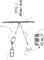
- FIG. 1 illustrated therein is a prior art system 100 in which an observer 101 may perceive speckle.
- a coherent light source 101 such as a semiconductor-type laser, delivers a coherent beam 104 to a modulation device 103.
- the modulation device 103 modulates the coherent beam 104 into a modulated coherent beam 105 capable of forming an image.
- This modulated coherent beam 105 is then delivered to a projection medium, such as the projection screen 107 shown in FIG. 1 .
- the reflected light 108 has portions that combine and portions that cancel.
- the observer 102 views an image 106 that appears to be speckled.
- speckle often tends to perceptibly degrade the quality of the image produced using the laser projection system.
- Prior art speckle reduction systems include attempts to introduce angle diversity into the coherent beam, attempts to introduce polarization diversity into the coherent beam, attempts to introduce wavelength diversity into the coherent beam, and so forth.
- Other devices employ diffusers, image displacing devices, and other complex systems.
- Some speckle reduction systems such as those used with microscopes, employ long lengths of optical fiber in an attempt to stretch the projected light beyond a corresponding coherence length prior to delivering it to a user.
- a drawback associated with each of these systems is that they add substantial cost and complexity to the overall system design. For instance, time-varying diffusers require moving or vibrating parts that adversely affect the overall system size and complexity. Further, such systems tend to increase the power requirements of the overall system, thereby degrading efficiency.
- US 2002/0154375 A1 discloses a system and method for reducing or eliminating the speckle intensity distribution in a laser imaging system.
- optical feedback is used to induce a laser light source for a projection system to create different speckle patterns that blend together on a projection surface.
- the optical feedback changes the laser emission from single mode to an effectively multimode pattern.
- the laser may be instantaneously single mode, but is forced to switch its mode structure rapidly.
- embodiments of the invention described herein may be comprised of one or more conventional processors and unique stored program instructions that control the one or more processors to implement, in conjunction with certain non-processor circuits, some, most, or all of the functions of reducing speckle as described herein.
- the non-processor circuits may include, but are not limited to, microprocessors, scanning mirrors, image modulation devices, memory devices, clock circuits, power circuits, and so forth. As such, these functions may be interpreted as steps of a method to perform speckle reduction.
- some or all functions could be implemented by a state machine that has no stored program instructions, or in one or more application specific integrated circuits, in which each function or some combinations of certain of the functions are implemented as custom logic.
- Embodiments of the present invention provide a multi-laser projection system with speckle reducing components.
- the speckle reduction is performed simply, in a low cost and efficient manner, by delivering optical feedback to the laser sources.
- the optical feedback first destabilizes the minimum linewidth mode of each laser source, and eventually results in coherence collapse when the amplitude of the optical feedback amplitude reaches a threshold.
- a plurality of laser sources is configured to produce a plurality of light beams.
- Optical elements such as dichroic mirrors, are then used to orient each of these light beams into a collimated, coherent light beam.
- a modulation device such as a Microelectromechanical System (MEMS) scanning mirror, digital light projection (DLP) system, or other modulation device, modulates the collimated, coherent light beam to present an image on a projection medium or display surface.
- MEMS Microelectromechanical System
- DLP digital light projection
- Speckle is reduced in embodiments of the invention via an optical feedback device, such as a partially reflective mirror, beam splitter-mirror combination, or other device capable of separating the collimated, coherent light beam into a projection component and a feedback component.
- the optical feedback device is disposed between the laser sources and the modulation device, thereby defining an external cavity with respect to each light source.
- the optical feedback device delivers the feedback component back to the laser sources, thereby causing each laser source to operate in a coherence collapsed state.
- the coherence collapsed state results in a projection beam that has a broader spectral width, which yields less perceived speckle.
- Embodiments of the invention are small and compact, and are suitable for use as projection systems in portable electronic devices.
- a plurality of laser sources 201 is configured to produce a plurality of light beams 204.
- the plurality of laser sources 201 comprises a red laser, a blue laser, and a green laser. These lasers can be edge emitting lasers or vertical cavity surface emitting lasers.
- each laser is a semiconductor laser that is small and efficient. Such lasers are commonly available from a variety of manufacturers.
- One or more optical alignment devices 220 are then used to orient the plurality of light beams 204 into a collimated light beam 205.
- the plurality of laser sources 201 comprise a red laser, blue laser, and green laser
- the one or more optical alignment devices 220 can blend the output of each laser to form a coherent beam of white light.
- dichroic mirrors can be used to orient the plurality of light beams 204 into the collimated light beam 205.
- Dichroic mirrors are partially reflective mirrors that include dichroic filters that selectively pass light in a narrow bandwidth while reflecting others. Dichroic mirrors and their use in laser-based projection systems are known in the art.
- a light modulator 203 is then configured to produce images 206 by modulating the collimated light beam and delivering it to a display surface 207.
- the light modulator 203 comprises a MEMS scanning mirror. Examples of MEMS scanning mirrors, such as those suitable for use with embodiments of the present invention, are set forth in US 2009/015929 A1 , entitled “Substrate-Guided Relays for Use with Scanned Beam Light Sources", and in US 2007/0159673 A1 , entitled, "Substrate-guided Display with Improved Image Quality".
- Embodiments of the invention are well suited for use with MEMS scanning mirrors as the overall system can be designed with a very small form factor, suitable for use in portable electronics such as mobile telephones, personal digital assistants, gaming devices, music players, multimedia devices, and so forth.
- portable electronics such as mobile telephones, personal digital assistants, gaming devices, music players, multimedia devices, and so forth.
- other light modulators such as digital light projection modulators, may be used as well.
- an optical feedback device 221 is disposed between the plurality of laser sources 201 and the light modulator 203.
- the optical feedback device 221 is disposed between the light modulator 203 and the one or more optical alignment devices 220.
- the optical axis running from the plurality of laser sources 201 and the optical feedback device 221 defines an external cavity 224 for each laser source.
- the optical feedback device 221 delivers a feedback component 222 to the plurality of laser sources 201, while delivering a projection component 223 to the light modulator 203.
- the feedback component 222 has amplitude sufficient to cause each of the plurality of laser sources 201 to operate in a state of coherence collapse.
- Coherence collapse causes considerable broadening of the spectral linewidth of the lasing modes of each of the plurality of laser sources 201. This reduces speckle appearing when images 206 from the light modulator 203 are displayed on the display surface 207.
- embodiments of the present invention exploit the coherence collapse phenomenon to suppress speckle effects in laser projection systems.
- the external cavity 224 which gives rise to the coherence collapse of each laser source, is defined by the optical path length between the facets of each of the plurality of laser sources 201 to the optical feedback device 221.
- the length of this external cavity 224 may be selected such that the desired linewidth broadening of each laser source is insensitive to external cavity phase, i.e., sub-wavelength changes in the external cavity length.
- the length of the external cavity 224 is chosen to be greater than the length below which the coherence collapse effect is not observed.
- the length of the external cavity 224 is selected to be an order of magnitude greater than the cavity length of each of the laser sources and less than the characteristic coherence length of each laser.
- the red laser may have a cavity length of roughly 1 millimeter, as will the blue laser.
- the green laser generally has a longer cavity length, such as 3-4 millimeters.
- the coherence length of each laser can run from several centimeters to hundreds of meters, but will often be on the order of tens of centimeters to a meter.
- the length of the external cavity 224 may be selected to be, for instance, about 10 millimeters long, which is greater than the cavity length of each laser source but less than the coherence length of the laser sources without feedback. In one embodiment of the invention, the length of the external cavity is between 0.1 and 100 millimeters.
- the amplitude of the feedback component 222 is selected to be greater than that which is needed to destabilize the minimum linewidth mode of each laser. Such feedback begins to excite multiple modes in each laser source, with each of these multiple modes being separated by a relaxation oscillation frequency corresponding to the laser. As the amplitude of the feedback component 222 reaches a threshold, each laser source is driven into coherence collapse, thereby considerably broadening the spectral linewidth of each source. This broadening reduces speckle seen by a viewer.
- the amount of feedback can be determined for a particular system or a particular manufacturer's laser diodes by employing a variable optical feedback device to tune the optical feedback to an amount sufficient to drive each of the plurality of laser sources 201 into coherence collapse.
- a system can be designed with a fixed optical feedback device having the desired reflectivity.
- the amount of feedback is at least enough as to destabilize a minimum linewidth mode of each of the laser sources.
- Experimental calculations based upon research show feedback having amplitude of approximately five percent of that of the collimated light beam 204 will cause sharp broadening in linewidth of each of the plurality of laser sources 201 due to the coherence collapse phenomenon.
- the coherence collapse phenomenon will be illustrated in more detail in FIGS. 3-5 .
- the laser source 301 has an internal cavity length and a coherence length associated therewith. Where the laser source is a red laser, the cavity length may be on the order of 1 millimeter, while the coherence length may be between 10 and 100 centimeters.
- the characteristic output 330 of the laser source is centered about a relaxation oscillation frequency 331 and has a spectral linewidth 332.
- this spectral linewidth 332 may be roughly 10 MHz.
- the laser source 301 having an optical feedback device 421 configured to deliver a feedback component 422 to the laser source 301 while delivering a projection component 423 to a light modulator 403 in accordance with embodiments of the invention.
- the amplitude of the feedback component 422 is relatively small, such as a few percent of the amplitude of the laser source's output.
- the amplitude of the feedback component 422 is sufficient as to destabilize the minimum linewidth mode of the laser source 301.
- the output 430 of the system is a plurality of excited modes that are separated by the relaxation oscillation frequency of the laser source 301.
- FIG. 5 illustrated therein is the system of FIG. 4 , with the amplitude of the feedback component 422 increased to around five percent of the amplitude of the laser source's output.
- the multi-mode output (430) of FIG. 4 has now become an output 530 in a coherence collapsed state.
- the initial spectral linewidth (332) of 10 MHz has now spread into a spectral linewidth of between 10 and 20 GHz. This broadening of the spectral linewitdh reduces the combinative effects of light reflecting from a display surface (207), thereby reducing speckle.
- prior art speckle reduction systems have attempted to use the "multi-mode" state of operation shown in FIG. 4 to reduce speckle.
- prior art systems generally require post modulator radiation alteration.
- prior art solutions in microscopes employ a single laser light source and then use extensive lengths of fiber optic cable in an attempt to deliver light at a distance from the source that exceeds the coherence length of the laser source.
- Embodiments of the present invention are not only able to use multiple laser light sources, but have no need for post modulator radiation alteration as each laser is drive into coherence collapse.
- each laser light source 661,662,663 is oriented so as to produce a plurality of light beams 604.
- Each laser light source 661,662,663 has a characteristic minimum linewidth mode and a coherence length associated therewith.
- the laser light sources 661,662,663 comprise a green laser light source, a red laser light source, and a blue laser light source.
- each laser light source 661,662,663 comprises a semiconductor laser source suitable for mounting on a printed wiring board or other substrate.
- a plurality of optical alignment 664,665,666 is configured to direct output light from each of the laser light sources 661,662,663 along an optical axis 667 as a coherent, collimated light beam.
- the plurality of optical alignment devices 664,665,666 each comprise dichroic mirrors. It will be clear to those of ordinary skill in the art having the benefit of this disclosure that other optical alignment devices configured to direct multiple light beams into a single collimated light beam may also be used.
- a light modulator 603 receives the collimated light and modulates it so as to produce images suitable for projection onto a display surface 207.
- the light modulator 603 comprises a MEMS scanning mirror 668.
- a partially reflecting mirror 669 directs the collimated light to the MEMS scanning mirror 668.
- other light modulating devices such as digital light projection systems, may be used in place of the MEMS scanning mirror 668.
- An advantage of the MEMS scanning mirror 668 is that it facilitates a very small, efficient light projection source 600.
- An optical feedback component 621 is then configured to reflect a feedback component of light along the optical axis 667 to the three laser light sources 661,662,663, thereby causing destabilization and spreading of each minimum linewidth mode.
- the amplitude of the feedback component is selected so as to drive each of the three laser light sources 661,662,663 into a coherence collapsed state.
- the optical feedback component 621 comprises a mirror having a partially reflective coating.
- Partially reflective coatings are generally known to those of ordinary skill in the art. Such coatings can be used to reflect some components of incident light and transmit others. Further, such coatings can be used transmit or reflect certain levels of light, or amounts of light that depend upon polarization. These coatings can be metallic layers - such as thin layers of silver. Alternatively, they may be multi-layer structures deposited by a vapor deposition process or other suitable manufacturing process. Additional details about the construction of suitable partially reflective coatings may be found in Application Serial No. 11/603,964 , entitled “Substrate-Guided Display with Improved Image Quality," filed November 21, 2006.
- Some coatings can be configured to preferentially reflect incident rays across a particular range of angles.
- several monolithic layers of partially reflecting material can be configured to exhibit a polarization preference, and angle preference, or a combination thereof.
- separate angle preferential and polarization preferential partial reflective layers may be used, with each layer contributing a portion of the reflected energy.
- the partially reflective coating on/in the optical feedback component 621 is configured to reflect between one and ten percent of the combined light beam coming from the plurality of optical alignment devices 664,665,666.
- the partially reflective coating comprises a multi-layer coating.
- the partially reflective coating can be configured to deliver feedback corresponding with a respective spectral width of each laser light source 661,662,663. By delivering the optical feedback, each laser light source 661,662,663 is driven into coherence collapse, thereby reducing perceived speckle from the light projection source 600.
- the optical feedback component 721 comprises a beam splitter 771 and mirror 772 combination.
- Beam splitters are devices that split a beam of light into multiple components.
- the beam splitter 771 is configured to split the received beam into a feedback component and a projection component.
- the beam splitter 771 delivers the feedback component, which may be between one and ten percent of the received collimated light beam, to the mirror 772.
- the feedback component reflects off the mirror 772 and is delivered back to the laser light sources 761,762,763, thereby causing coherence collapse.
- Beam splitters 771 suitable for use with the invention can take many forms, including cubed prisms, half-silvered mirrors, and dichroic mirrored prism assemblies.
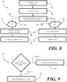
- a plurality of light sources produces at least two beams of light.
- one or more optical alignment devices orient the at least two light beams into a collimated beam.
- an optical feedback device separates the collimated beam into a projection component 805 and a feedback component 804.
- the projection component amplitude is between one and ten percent of the amplitude of the collimated light beam.
- This step 803 can include the step of disposing the feedback component between 0.1 millimeters and 100 millimeters away from the laser light sources along an optical axis running from the laser light sources to the optical feedback device.
- the optical feedback device delivers the projection component to a modulation device so that images can be projected to a user at step 807.
- the modulation device forms the image presentation and delivers the image presentation to the display surface for viewing.
- the optical feedback device delivers the feedback component 804 to the laser light sources, thereby causing each of the laser light sources to operate in a coherence collapsed state at step 809.
- step 803 of FIG. 8 can be carried out.
- the step 803 of separating the collimated beam into the projection component and the feedback component can comprises either the step 901 of providing a partially reflective mirror or the step 902 of providing a system comprising a beam splitter and mirror.
- the steps of FIG. 9 are illustrative only, as other types of optical feedback devices may be supplied in lieu of a partially reflective mirror or a beam splitter/mirror combination.
- imaging systems 200 as set forth herein may be incorporated into a device 1000.
- the device 1000 may be any of a mobile telephone, a portable DVD player, a portable television device, a laptop, a portable e-mail device, a portable music player, a personal digital assistant, or any combination of the same.
- the device 1000 may include a projector 1001 incorporating any one or more of the foregoing speckle reduction apparatuses and configured to execute any one or more of the foregoing speckle reduction methods.
- the projector 1001 in one embodiment, is coupled to a processor 1002 programmed to control the projector 1001.
- the projector 1001 includes the laser light sources 201 and the optical feedback component 221 and other speckle reduction components described herein.
- the processor 1002 may be coupled to a memory 1003 storing image data 1004, which may include either still image or video data.
- the processor 1002 may be programmed to process the image data to generate control signals causing the projector 1001 to create an image corresponding to the image data 1004 on the display surface 1007.
- the processor 1007 may also be coupled to one or more input and output devices.
- a display 1005 may enable a user to view the status of operation of the processor 1002 and may serve as an alternative means for displaying the image data 1004.
- the processor 1002 may also be coupled to a keypad 1006 for receiving user inputs and control instructions.
Landscapes
- Physics & Mathematics (AREA)
- Engineering & Computer Science (AREA)
- Multimedia (AREA)
- Signal Processing (AREA)
- General Physics & Mathematics (AREA)
- Optics & Photonics (AREA)
- Projection Apparatus (AREA)
- Mechanical Optical Scanning Systems (AREA)
- Lasers (AREA)
- Semiconductor Lasers (AREA)
Claims (15)
- Bildgebungssystem (200), umfassend:mehrere Laserquellen (201, 301, 661-663, 761-763), die zum Erzeugen mehrerer Lichtstrahlen (204, 604) konfiguriert sind;eine oder mehrere optische Ausrichteinrichtungen (220, 664-666), die zum Ausrichten der mehreren Lichtstrahlen (204, 604) in einen kollimierten Lichtstrahl (205) konfiguriert ist/sind;einen Lichtmodulator (203, 403, 603, 703), der zum Erzeugen von Bildern (206) mit dem kollimierten Lichtstrahl (204, 604) konfiguriert ist; undeine optische Rückkopplungseinrichtung (221, 421, 621, 721), die derart konfiguriert ist, dass sie eine Lichtmenge an die mehreren Laserquellen (201, 301, 661-663, 761-763) zurücksendet, um einen Modus minimaler Linienbreite jeder der mehreren Laserquellen (201, 301, 661-663, 761-763) zu destabilisieren und aufzuweiten, um zu bewirken, dass jede der mehreren Laserquellen (201, 301, 661-663, 761-763) in einem Zustand zusammengebrochener Kohärenz arbeitet, um ein Auftreten von Flecken zu reduzieren, wenn die Bilder (206) auf einer Anzeigefläche (207, 1007) dargestellt werden.
- Bildgebungssystem nach Anspruch 1, wobei jede der mehreren Laserquellen (201, 301, 661-663, 761-763) eine innere Kavitätslänge und eine damit in Beziehung stehende Kohärenzlänge aufweist, wobei mehrere äußere Kavitäten (224) durch mehrere optische Achsen (667) definiert sind, die von einer jeweiligen der mehreren Laserquellen (201, 301, 661-663, 761-763) zur optischen Rückkopplungseinrichtung (221, 421, 621, 721) verlaufen, wobei jeder der mehreren äußeren Kavitäten (224) eine jeweilige äußere Kavitätslänge aufweist, die zwischen der inneren Kavitätslänge und der Kohärenzlänge liegt.
- Bildgebungssystem nach Anspruch 2, wobei die äußere Kavitätslänge zwischen 0,1 Millimeter und 100 Millimeter beträgt.
- Bildgebungssystem nach Anspruch 1, wobei der Lichtmodulator (203, 403, 603, 703) zum Erzeugen der Bilder (206) mit dem kollimierten Lichtstrahl (205) ohne Nachmodulator-Strahlungsänderung konfiguriert ist.
- Bildgebungssystem nach Anspruch 1, wobei die optische Rückkopplungseinrichtung (221, 421, 621, 721) einen Spiegel (669) mit einer teilweise reflektierenden Beschichtung aufweist.
- Bildgebungssystem nach Anspruch 5.wobei die teilweise reflektierende Beschichtung derart konfiguriert ist, dass sie zwischen einem Prozent und zehn Prozent des kollimierten Lichtstrahls (205) reflektiert, und/oderwobei die teilweise reflektierende Beschichtung eine mehrschichtige teilweise reflektierende Beschichtung umfasst.
- Bildgebungssystem nach Anspruch 5, wobei die teilweise reflektierende Beschichtung eine mehrschichtige teilweise reflektierende Beschichtung umfasst und die mehreren Laserquellen (201, 301, 661-663, 761-763) drei Laserquellen (201, 301, 661-663, 761-763) umfassen, wobei jede Laserquelle (201, 301, 661-663, 761-763) Licht mit drei vorbestimmten Spektralbreiten erzeugt, wobei die mehrschichtige teilweise reflektierende Beschichtung derart konfiguriert ist, dass sie eine Rückkopplung entsprechend den drei vorbestimmten Spektralbreiten liefert.
- Bildgebungssystem nach Anspruch 1,wobei die eine oder die mehreren optischen Ausrichteinrichtungen (220, 664-666) drei dichroitische Spiegel umfasst/umfassen, oderwobei die eine oder die mehreren optischen Ausrichteinrichtungen (220, 664-666) drei dichroitische Spiegel umfasst/umfassen und der Lichtmodulator (203, 403, 603, 703) einen MEMS-Scanspiegel (668) umfasst.
- Bildgebungssystem nach Anspruch 1, wobei die optische Rückkopplungseinrichtung (221, 421, 621, 721) einen Strahlteiler (771) und einen reflektierenden Spiegel (772) umfasst, wobei der Strahlteiler (771) zum Lenken eines Teils des kollimierten Lichtstrahls (205) zu dem reflektierenden Spiegel (772) konfiguriert ist.
- Bildgebungssystem nach Anspruch 9, wobei der Teil zwischen einem Prozent und zehn Prozent des kollimierten Lichtstrahls (205) umfasst.
- Bildgebungssystem nach einem der Ansprüche 1-10,
wobei die mehreren Laserquellen (201, 301, 661-663, 761-763) eine rote Laserlichtquelle, eine grüne Laserlichtquelle und eine blaue Laserlichtquelle umfassen, und/oder wobei die optische Rückkopplungseinrichtung (221, 421, 621, 721) zwischen der einen oder den mehreren optischen Ausrichteinrichtungen (220, 664-666) und dem Lichtmodulator (203, 403, 603, 703) angeordnet ist. - Bildgebungssystem nach einem der Ansprüche 1-11,wobei die optische Rückkopplungseinrichtung (221, 421, 621, 721) derart konfiguriert ist, dass sie bewirkt, dass jede der mehreren Laserquellen (201, 301, 661-663, 761-763) mit einer Spektrumslinienbreite von mindestens 10 GHz arbeitet, und/oderwobei der Betrag optischer Rückkopplung, der an die mehreren Laserquellen (201, 301, 661-663, 761-763) geliefert wird, größer ist als ein Betrag optischer Rückkopplung, der jede der mehreren Laserquellen (201, 301, 661-663, 761-763) veranlassen würde, in mehreren angeregten Moden zu arbeiten, die durch eine Relaxationsoszillationsfrequenz der jeweiligen Laserquelle (201, 301, 661-663, 761-763) getrennt sind.
- Verfahren zum Reduzieren von Flecken, das mit dem Bildgebungssystem nach Anspruch 1 in Beziehung steht, in einer Bilddarstellung auf einer Anzeigefläche (207, 1007), wobei das Verfahren die folgenden Schritte umfasst:Erzeugen mindestens zweier Lichtstrahlen (204, 604) aus Laserquellen (201, 301, 661-663, 761-763);Ausrichten der mindestens zwei Lichtstrahlen (204, 604) in einen kollimierten Strahl (205);Trennen des kollimierten Strahls (205) in eine Projektionskomponente (223, 423, 805) und eine Rückkopplungskomponente (222, 422, 804);Liefern der Projektionskomponente (223, 423, 805) an eine Modulationseinrichtung (203, 403, 603, 703); undLiefern der Rückkopplungskomponente (222, 422, 804) an die Laserquellen (201, 301, 661-663, 761-763), um einen Modus minimaler Linienbreite jeder der Laserquellen (201, 301, 661-663, 761-763) zu destabilisieren und aufzuweiten, und um zu bewirken, dass jede der Laserquellen (201, 301, 661-663, 761-763) in einem Zustand zusammengebrochener Kohärenz arbeitet.
- Verfahren nach Anspruch 13,ferner den Schritt umfassend, dass die Modulationseinrichtung (203, 403, 603, 703) veranlasst wird, die Bilddarstellung zu erzeugen und die Bilddarstellung an die Anzeigefläche (207, 1007) zu liefern, und/oderwobei die Rückkopplungskomponente (222, 422, 804) zwischen einem Prozent und zehn Prozent des kollimierten Strahls (205) umfasst.
- Verfahren nach Anspruch 13,wobei der Schritt des Trennens des kollimierten Strahls (205) in die Projektionskomponente (223, 423, 805) und die Rückkopplungskomponente (222, 422, 804) den Schritt des Bereitstellens eines teilweise reflektierenden Spiegels (669) oder eines einen Strahlteiler (771) und einen Spiegel (772) aufweisenden Systems umfasst, oderwobei der Schritt des Trennens des kollimierten Strahls (205) in die Projektionskomponente (223, 423, 805) und die Rückkopplungskomponente (222, 422, 804) den Schritt des Bereitstellens eines teilweise reflektierenden Spiegels (669) oder eines einen Strahlteiler (771) und einen Spiegel (772) aufweisenden Systems umfasst, und den Schritt umfasst, dass die Rückkopplungskomponente (222, 422, 804) mit einem Abstand von zwischen 0,1 Millimeter und 100 Millimeter zu den Laserquellen (201, 301, 661-663, 761-763) entlang einer optischen Achse (667), die von den Laserquellen (201, 301, 661-663, 761-763) zur Rücckopplungskomponente (222, 422, 804) verläuft, angeordnet wird.
Applications Claiming Priority (2)
| Application Number | Priority Date | Filing Date | Title |
|---|---|---|---|
| US12/241,597 US7993012B2 (en) | 2008-09-30 | 2008-09-30 | Laser display system with optical feedback configured to reduce speckle artifacts |
| PCT/US2009/054676 WO2010039351A1 (en) | 2008-09-30 | 2009-08-21 | Laser display system with optical feedback configured to reduce speckle artifacts |
Publications (3)
| Publication Number | Publication Date |
|---|---|
| EP2332010A1 EP2332010A1 (de) | 2011-06-15 |
| EP2332010A4 EP2332010A4 (de) | 2015-04-29 |
| EP2332010B1 true EP2332010B1 (de) | 2019-05-15 |
Family
ID=42057439
Family Applications (1)
| Application Number | Title | Priority Date | Filing Date |
|---|---|---|---|
| EP09818174.6A Not-in-force EP2332010B1 (de) | 2008-09-30 | 2009-08-21 | Laseranzeigesystem mit optischem feedback zur reduzierung von speckle-artefakten |
Country Status (5)
| Country | Link |
|---|---|
| US (2) | US7993012B2 (de) |
| EP (1) | EP2332010B1 (de) |
| JP (1) | JP2012504338A (de) |
| CN (1) | CN102171608B (de) |
| WO (1) | WO2010039351A1 (de) |
Cited By (1)
| Publication number | Priority date | Publication date | Assignee | Title |
|---|---|---|---|---|
| US12597755B2 (en) | 2022-10-19 | 2026-04-07 | The University Of British Columbia | Electronically-controlled optical feedback methods for laser linewidth |
Families Citing this family (9)
| Publication number | Priority date | Publication date | Assignee | Title |
|---|---|---|---|---|
| JP5914329B2 (ja) * | 2010-05-24 | 2016-05-11 | ギガフォトン株式会社 | 固体レーザ装置およびレーザシステム |
| US8308302B2 (en) * | 2010-07-13 | 2012-11-13 | Microvision, Inc. | Laser scanning imaging system with reduced speckle |
| JP2013125693A (ja) | 2011-12-15 | 2013-06-24 | Koito Mfg Co Ltd | 車両用灯具 |
| US10070016B2 (en) * | 2016-02-16 | 2018-09-04 | Microvision, Inc. | Multi-stripes lasers for laser based projector displays |
| JP6880566B2 (ja) * | 2016-04-25 | 2021-06-02 | 株式会社リコー | 光源装置、画像形成装置、画像表示装置、物体装置及び色光生成方法 |
| US10481408B2 (en) | 2016-09-30 | 2019-11-19 | Christie Digital Systems (Usa), Inc. | Apparatus for reducing coherence of a laser beam |
| CA3180640A1 (en) * | 2020-05-13 | 2021-11-18 | The University Of British Columbia | Electronically-controlled optical feedback methods for laser linewidth reduction |
| US12132296B2 (en) * | 2021-05-14 | 2024-10-29 | Microsoft Technology Licensing, Llc | Laser having reduced coherence via a phaser shifter |
| EP4646626A2 (de) * | 2023-01-03 | 2025-11-12 | Board of Regents, The University of Texas System | System und verfahren zur faserbasierten laser-speckle-bildgebung |
Family Cites Families (21)
| Publication number | Priority date | Publication date | Assignee | Title |
|---|---|---|---|---|
| JPS61260728A (ja) * | 1985-05-14 | 1986-11-18 | Sharp Corp | 光アナログ情報伝送方式 |
| JPH10166643A (ja) * | 1996-12-09 | 1998-06-23 | Fuji Photo Film Co Ltd | レーザ露光装置 |
| US6445487B1 (en) * | 2001-02-20 | 2002-09-03 | Eastman Kodak Company | Speckle suppressed laser projection system using a multi-wavelength doppler shifted beam |
| US6600590B2 (en) * | 2001-02-20 | 2003-07-29 | Eastman Kodak Company | Speckle suppressed laser projection system using RF injection |
| US6625381B2 (en) * | 2001-02-20 | 2003-09-23 | Eastman Kodak Company | Speckle suppressed laser projection system with partial beam reflection |
| JP2004045684A (ja) * | 2002-07-11 | 2004-02-12 | Sony Corp | 画像表示装置における照明光学装置及び画像表示装置 |
| CN100392494C (zh) * | 2003-03-28 | 2008-06-04 | 精工爱普生株式会社 | 具有微细结构元件的空间光调制装置和投影机及制造方法 |
| KR100744892B1 (ko) | 2003-03-28 | 2007-08-01 | 세이코 엡슨 가부시키가이샤 | 공간 광 변조 장치와 이 공간 광 변조 장치를 갖는 프로젝터 |
| US7379651B2 (en) * | 2003-06-10 | 2008-05-27 | Abu-Ageel Nayef M | Method and apparatus for reducing laser speckle |
| US20050140930A1 (en) * | 2003-12-31 | 2005-06-30 | Symbol Technologies, Inc. | Color laser projection display |
| EP1869526B1 (de) * | 2005-03-30 | 2019-11-06 | Necsel Intellectual Property, Inc. | Herstellbare oberflächenemissions-laserarrays mit vertikalem erweitertem resonator |
| WO2006116477A2 (en) * | 2005-04-25 | 2006-11-02 | Massachusetts Institute Of Technology | Multi-wavelength beam combiner |
| DE602006015388D1 (de) | 2005-05-09 | 2010-08-26 | Lg Electronics Inc | Optisches System eines tragbaren Projektors und mobiles Kommunikationsendgerät damit |
| KR100767671B1 (ko) * | 2005-05-09 | 2007-10-18 | 엘지전자 주식회사 | 휴대가능한 프로젝터용 광학시스템 |
| JP2006317681A (ja) | 2005-05-12 | 2006-11-24 | Canon Inc | 画像表示装置 |
| KR101065065B1 (ko) * | 2005-12-14 | 2011-09-15 | 삼성엘이디 주식회사 | 레이저 디스플레이 장치 |
| US7627013B2 (en) * | 2006-02-03 | 2009-12-01 | Hewlett-Packard Development Company, L.P. | Light source module |
| JP5231990B2 (ja) * | 2006-03-03 | 2013-07-10 | パナソニック株式会社 | 照明光源及びレーザ投射装置 |
| US7665853B2 (en) | 2006-06-05 | 2010-02-23 | Symbol Technologies, Inc. | Arrangement for, and method of, enhancing image projection by holding scan mirror steady during part of mirror drive cycle |
| US20080095203A1 (en) * | 2006-10-19 | 2008-04-24 | Bratkovski Alexandre M | Multi-emitter image formation with reduced speckle |
| US7972020B2 (en) | 2006-12-29 | 2011-07-05 | Texas Instruments Incorporated | Apparatus and method for reducing speckle in display of images |
-
2008
- 2008-09-30 US US12/241,597 patent/US7993012B2/en not_active Expired - Fee Related
-
2009
- 2009-08-21 EP EP09818174.6A patent/EP2332010B1/de not_active Not-in-force
- 2009-08-21 JP JP2011529052A patent/JP2012504338A/ja active Pending
- 2009-08-21 CN CN2009801387470A patent/CN102171608B/zh not_active Expired - Fee Related
- 2009-08-21 WO PCT/US2009/054676 patent/WO2010039351A1/en not_active Ceased
-
2011
- 2011-05-03 US US13/100,158 patent/US8070298B2/en not_active Expired - Fee Related
Non-Patent Citations (3)
| Title |
|---|
| J S COHEN ET AL: "NOISE, CHAOS AND COHERENCE COLLAPSE IN SEMICONDUCTOR LASERS", PHILIPS JOURNALOF RESEARCH, 1 January 1989 (1989-01-01), pages 43 - 55, XP055517976, Retrieved from the Internet <URL:http://www.extra.research.philips.com/hera/people/aarts/_Philips%20Bound%20Archive/PJR/PJR-44-1989_90-043.pdf> * |
| J.S. COHEN ET AL: "Spectral properties of the coherence collapsed state of a semiconductor laser with delayed optical feedback", IEEE JOURNAL OF QUANTUM ELECTRONICS., vol. 25, no. 6, 1 June 1989 (1989-06-01), USA, pages 1143 - 1151, XP055517971, ISSN: 0018-9197, DOI: 10.1109/3.29239 * |
| S AZOUIGUI ET AL: "Coherence collapse and low-frequency fluctuations in quantum-dash based lasers emitting at 1.57 [mu]m", OPTICS EXPRESS, 1 January 2007 (2007-01-01), pages 14155 - 1661, XP055517992, Retrieved from the Internet <URL:https://www.osapublishing.org/DirectPDFAccess/3DFE0A62-F804-882C-47AF1964586DEF2C_144188/oe-15-21-14155.pdf?da=1&id=144188&seq=0&mobile=no> DOI: 10.1364/OE.15.014155 * |
Cited By (1)
| Publication number | Priority date | Publication date | Assignee | Title |
|---|---|---|---|---|
| US12597755B2 (en) | 2022-10-19 | 2026-04-07 | The University Of British Columbia | Electronically-controlled optical feedback methods for laser linewidth |
Also Published As
| Publication number | Publication date |
|---|---|
| CN102171608B (zh) | 2012-08-08 |
| EP2332010A1 (de) | 2011-06-15 |
| US8070298B2 (en) | 2011-12-06 |
| US20110205504A1 (en) | 2011-08-25 |
| EP2332010A4 (de) | 2015-04-29 |
| WO2010039351A1 (en) | 2010-04-08 |
| US20100080253A1 (en) | 2010-04-01 |
| JP2012504338A (ja) | 2012-02-16 |
| US7993012B2 (en) | 2011-08-09 |
| CN102171608A (zh) | 2011-08-31 |
Similar Documents
| Publication | Publication Date | Title |
|---|---|---|
| EP2332010B1 (de) | Laseranzeigesystem mit optischem feedback zur reduzierung von speckle-artefakten | |
| US8049825B2 (en) | Laser projection source with birefringent wedge for speckle reduction | |
| JP5484449B2 (ja) | 空間的及び時間的混合を用いるレーザ投影 | |
| US6945652B2 (en) | Projection display device | |
| US7359420B2 (en) | Manufacturable vertical extended cavity surface emitting laser arrays | |
| US8427731B2 (en) | Display apparatus, method and light source | |
| US20120044279A1 (en) | Image Projection Apparatus and Laser Beam Projection Apparatus | |
| US7972008B2 (en) | Projection system using high-frequency drive modulation to reduce perceived speckle | |
| CN105474073A (zh) | 光源装置、尤其在微镜装置中使用的光源装置 | |
| WO2007092710A2 (en) | Light source module | |
| JP2011508286A (ja) | 光信号の偏光変調のためのシステム及び方法 | |
| EP3973601B1 (de) | Kantenemittierender laser mit hochfrequenzmoduliertem reflektorabschnitt | |
| US8395714B2 (en) | Scanned projection system using polymerized liquid crystal layer for speckle reduction | |
| KR101583113B1 (ko) | 레이저 프로젝터 | |
| EP4331066A1 (de) | Sichtbare lichtquelle mit integrierten vcsels und integrierten photonischen hohlräumen | |
| JP2010191173A (ja) | レーザ投射装置 | |
| JP5505121B2 (ja) | 集光光学ユニット、光走査装置、投影型画像表示装置及び電子機器 | |
| US7446931B2 (en) | Compact multicolor light beam source | |
| WO2022232076A1 (en) | Multi-color visible light source including integrated vcsels and integrated photonic cavities | |
| JP2010249980A (ja) | レーザ投射装置および画像投影装置 |
Legal Events
| Date | Code | Title | Description |
|---|---|---|---|
| PUAI | Public reference made under article 153(3) epc to a published international application that has entered the european phase |
Free format text: ORIGINAL CODE: 0009012 |
|
| 17P | Request for examination filed |
Effective date: 20110407 |
|
| AK | Designated contracting states |
Kind code of ref document: A1 Designated state(s): AT BE BG CH CY CZ DE DK EE ES FI FR GB GR HR HU IE IS IT LI LT LU LV MC MK MT NL NO PL PT RO SE SI SK SM TR |
|
| AX | Request for extension of the european patent |
Extension state: AL BA RS |
|
| DAX | Request for extension of the european patent (deleted) | ||
| RAP1 | Party data changed (applicant data changed or rights of an application transferred) |
Owner name: MICROVISION, INC. |
|
| RA4 | Supplementary search report drawn up and despatched (corrected) |
Effective date: 20150327 |
|
| RIC1 | Information provided on ipc code assigned before grant |
Ipc: G03B 21/00 20060101AFI20150323BHEP Ipc: H01S 5/065 20060101ALI20150323BHEP Ipc: H01S 5/40 20060101ALI20150323BHEP Ipc: H04N 9/31 20060101ALI20150323BHEP |
|
| GRAP | Despatch of communication of intention to grant a patent |
Free format text: ORIGINAL CODE: EPIDOSNIGR1 |
|
| STAA | Information on the status of an ep patent application or granted ep patent |
Free format text: STATUS: GRANT OF PATENT IS INTENDED |
|
| INTG | Intention to grant announced |
Effective date: 20181123 |
|
| GRAS | Grant fee paid |
Free format text: ORIGINAL CODE: EPIDOSNIGR3 |
|
| GRAA | (expected) grant |
Free format text: ORIGINAL CODE: 0009210 |
|
| STAA | Information on the status of an ep patent application or granted ep patent |
Free format text: STATUS: THE PATENT HAS BEEN GRANTED |
|
| AK | Designated contracting states |
Kind code of ref document: B1 Designated state(s): AT BE BG CH CY CZ DE DK EE ES FI FR GB GR HR HU IE IS IT LI LT LU LV MC MK MT NL NO PL PT RO SE SI SK SM TR |
|
| REG | Reference to a national code |
Ref country code: CH Ref legal event code: EP Ref country code: GB Ref legal event code: FG4D |
|
| REG | Reference to a national code |
Ref country code: DE Ref legal event code: R096 Ref document number: 602009058390 Country of ref document: DE |
|
| REG | Reference to a national code |
Ref country code: IE Ref legal event code: FG4D |
|
| REG | Reference to a national code |
Ref country code: NL Ref legal event code: MP Effective date: 20190515 |
|
| REG | Reference to a national code |
Ref country code: LT Ref legal event code: MG4D |
|
| PG25 | Lapsed in a contracting state [announced via postgrant information from national office to epo] |
Ref country code: NO Free format text: LAPSE BECAUSE OF FAILURE TO SUBMIT A TRANSLATION OF THE DESCRIPTION OR TO PAY THE FEE WITHIN THE PRESCRIBED TIME-LIMIT Effective date: 20190815 Ref country code: FI Free format text: LAPSE BECAUSE OF FAILURE TO SUBMIT A TRANSLATION OF THE DESCRIPTION OR TO PAY THE FEE WITHIN THE PRESCRIBED TIME-LIMIT Effective date: 20190515 Ref country code: SE Free format text: LAPSE BECAUSE OF FAILURE TO SUBMIT A TRANSLATION OF THE DESCRIPTION OR TO PAY THE FEE WITHIN THE PRESCRIBED TIME-LIMIT Effective date: 20190515 Ref country code: NL Free format text: LAPSE BECAUSE OF FAILURE TO SUBMIT A TRANSLATION OF THE DESCRIPTION OR TO PAY THE FEE WITHIN THE PRESCRIBED TIME-LIMIT Effective date: 20190515 Ref country code: PT Free format text: LAPSE BECAUSE OF FAILURE TO SUBMIT A TRANSLATION OF THE DESCRIPTION OR TO PAY THE FEE WITHIN THE PRESCRIBED TIME-LIMIT Effective date: 20190915 Ref country code: LT Free format text: LAPSE BECAUSE OF FAILURE TO SUBMIT A TRANSLATION OF THE DESCRIPTION OR TO PAY THE FEE WITHIN THE PRESCRIBED TIME-LIMIT Effective date: 20190515 Ref country code: HR Free format text: LAPSE BECAUSE OF FAILURE TO SUBMIT A TRANSLATION OF THE DESCRIPTION OR TO PAY THE FEE WITHIN THE PRESCRIBED TIME-LIMIT Effective date: 20190515 Ref country code: ES Free format text: LAPSE BECAUSE OF FAILURE TO SUBMIT A TRANSLATION OF THE DESCRIPTION OR TO PAY THE FEE WITHIN THE PRESCRIBED TIME-LIMIT Effective date: 20190515 |
|
| PG25 | Lapsed in a contracting state [announced via postgrant information from national office to epo] |
Ref country code: GR Free format text: LAPSE BECAUSE OF FAILURE TO SUBMIT A TRANSLATION OF THE DESCRIPTION OR TO PAY THE FEE WITHIN THE PRESCRIBED TIME-LIMIT Effective date: 20190816 Ref country code: BG Free format text: LAPSE BECAUSE OF FAILURE TO SUBMIT A TRANSLATION OF THE DESCRIPTION OR TO PAY THE FEE WITHIN THE PRESCRIBED TIME-LIMIT Effective date: 20190815 Ref country code: LV Free format text: LAPSE BECAUSE OF FAILURE TO SUBMIT A TRANSLATION OF THE DESCRIPTION OR TO PAY THE FEE WITHIN THE PRESCRIBED TIME-LIMIT Effective date: 20190515 |
|
| REG | Reference to a national code |
Ref country code: AT Ref legal event code: MK05 Ref document number: 1134132 Country of ref document: AT Kind code of ref document: T Effective date: 20190515 |
|
| PG25 | Lapsed in a contracting state [announced via postgrant information from national office to epo] |
Ref country code: CZ Free format text: LAPSE BECAUSE OF FAILURE TO SUBMIT A TRANSLATION OF THE DESCRIPTION OR TO PAY THE FEE WITHIN THE PRESCRIBED TIME-LIMIT Effective date: 20190515 Ref country code: RO Free format text: LAPSE BECAUSE OF FAILURE TO SUBMIT A TRANSLATION OF THE DESCRIPTION OR TO PAY THE FEE WITHIN THE PRESCRIBED TIME-LIMIT Effective date: 20190515 Ref country code: EE Free format text: LAPSE BECAUSE OF FAILURE TO SUBMIT A TRANSLATION OF THE DESCRIPTION OR TO PAY THE FEE WITHIN THE PRESCRIBED TIME-LIMIT Effective date: 20190515 Ref country code: DK Free format text: LAPSE BECAUSE OF FAILURE TO SUBMIT A TRANSLATION OF THE DESCRIPTION OR TO PAY THE FEE WITHIN THE PRESCRIBED TIME-LIMIT Effective date: 20190515 Ref country code: AT Free format text: LAPSE BECAUSE OF FAILURE TO SUBMIT A TRANSLATION OF THE DESCRIPTION OR TO PAY THE FEE WITHIN THE PRESCRIBED TIME-LIMIT Effective date: 20190515 Ref country code: SK Free format text: LAPSE BECAUSE OF FAILURE TO SUBMIT A TRANSLATION OF THE DESCRIPTION OR TO PAY THE FEE WITHIN THE PRESCRIBED TIME-LIMIT Effective date: 20190515 |
|
| REG | Reference to a national code |
Ref country code: DE Ref legal event code: R097 Ref document number: 602009058390 Country of ref document: DE |
|
| PG25 | Lapsed in a contracting state [announced via postgrant information from national office to epo] |
Ref country code: IT Free format text: LAPSE BECAUSE OF FAILURE TO SUBMIT A TRANSLATION OF THE DESCRIPTION OR TO PAY THE FEE WITHIN THE PRESCRIBED TIME-LIMIT Effective date: 20190515 Ref country code: SM Free format text: LAPSE BECAUSE OF FAILURE TO SUBMIT A TRANSLATION OF THE DESCRIPTION OR TO PAY THE FEE WITHIN THE PRESCRIBED TIME-LIMIT Effective date: 20190515 |
|
| PLBE | No opposition filed within time limit |
Free format text: ORIGINAL CODE: 0009261 |
|
| STAA | Information on the status of an ep patent application or granted ep patent |
Free format text: STATUS: NO OPPOSITION FILED WITHIN TIME LIMIT |
|
| PG25 | Lapsed in a contracting state [announced via postgrant information from national office to epo] |
Ref country code: TR Free format text: LAPSE BECAUSE OF FAILURE TO SUBMIT A TRANSLATION OF THE DESCRIPTION OR TO PAY THE FEE WITHIN THE PRESCRIBED TIME-LIMIT Effective date: 20190515 |
|
| 26N | No opposition filed |
Effective date: 20200218 |
|
| PG25 | Lapsed in a contracting state [announced via postgrant information from national office to epo] |
Ref country code: PL Free format text: LAPSE BECAUSE OF FAILURE TO SUBMIT A TRANSLATION OF THE DESCRIPTION OR TO PAY THE FEE WITHIN THE PRESCRIBED TIME-LIMIT Effective date: 20190515 |
|
| PG25 | Lapsed in a contracting state [announced via postgrant information from national office to epo] |
Ref country code: CH Free format text: LAPSE BECAUSE OF NON-PAYMENT OF DUE FEES Effective date: 20190831 Ref country code: SI Free format text: LAPSE BECAUSE OF FAILURE TO SUBMIT A TRANSLATION OF THE DESCRIPTION OR TO PAY THE FEE WITHIN THE PRESCRIBED TIME-LIMIT Effective date: 20190515 Ref country code: LU Free format text: LAPSE BECAUSE OF NON-PAYMENT OF DUE FEES Effective date: 20190821 Ref country code: LI Free format text: LAPSE BECAUSE OF NON-PAYMENT OF DUE FEES Effective date: 20190831 Ref country code: MC Free format text: LAPSE BECAUSE OF FAILURE TO SUBMIT A TRANSLATION OF THE DESCRIPTION OR TO PAY THE FEE WITHIN THE PRESCRIBED TIME-LIMIT Effective date: 20190515 |
|
| REG | Reference to a national code |
Ref country code: BE Ref legal event code: MM Effective date: 20190831 |
|
| PG25 | Lapsed in a contracting state [announced via postgrant information from national office to epo] |
Ref country code: IE Free format text: LAPSE BECAUSE OF NON-PAYMENT OF DUE FEES Effective date: 20190821 |
|
| PG25 | Lapsed in a contracting state [announced via postgrant information from national office to epo] |
Ref country code: BE Free format text: LAPSE BECAUSE OF NON-PAYMENT OF DUE FEES Effective date: 20190831 |
|
| PGFP | Annual fee paid to national office [announced via postgrant information from national office to epo] |
Ref country code: GB Payment date: 20200813 Year of fee payment: 12 Ref country code: FR Payment date: 20200715 Year of fee payment: 12 Ref country code: DE Payment date: 20200812 Year of fee payment: 12 |
|
| PG25 | Lapsed in a contracting state [announced via postgrant information from national office to epo] |
Ref country code: CY Free format text: LAPSE BECAUSE OF FAILURE TO SUBMIT A TRANSLATION OF THE DESCRIPTION OR TO PAY THE FEE WITHIN THE PRESCRIBED TIME-LIMIT Effective date: 20190515 |
|
| PG25 | Lapsed in a contracting state [announced via postgrant information from national office to epo] |
Ref country code: IS Free format text: LAPSE BECAUSE OF FAILURE TO SUBMIT A TRANSLATION OF THE DESCRIPTION OR TO PAY THE FEE WITHIN THE PRESCRIBED TIME-LIMIT Effective date: 20190915 |
|
| PG25 | Lapsed in a contracting state [announced via postgrant information from national office to epo] |
Ref country code: HU Free format text: LAPSE BECAUSE OF FAILURE TO SUBMIT A TRANSLATION OF THE DESCRIPTION OR TO PAY THE FEE WITHIN THE PRESCRIBED TIME-LIMIT; INVALID AB INITIO Effective date: 20090821 Ref country code: MT Free format text: LAPSE BECAUSE OF FAILURE TO SUBMIT A TRANSLATION OF THE DESCRIPTION OR TO PAY THE FEE WITHIN THE PRESCRIBED TIME-LIMIT Effective date: 20190515 |
|
| REG | Reference to a national code |
Ref country code: DE Ref legal event code: R119 Ref document number: 602009058390 Country of ref document: DE |
|
| GBPC | Gb: european patent ceased through non-payment of renewal fee |
Effective date: 20210821 |
|
| PG25 | Lapsed in a contracting state [announced via postgrant information from national office to epo] |
Ref country code: MK Free format text: LAPSE BECAUSE OF FAILURE TO SUBMIT A TRANSLATION OF THE DESCRIPTION OR TO PAY THE FEE WITHIN THE PRESCRIBED TIME-LIMIT Effective date: 20190515 |
|
| PG25 | Lapsed in a contracting state [announced via postgrant information from national office to epo] |
Ref country code: GB Free format text: LAPSE BECAUSE OF NON-PAYMENT OF DUE FEES Effective date: 20210821 Ref country code: FR Free format text: LAPSE BECAUSE OF NON-PAYMENT OF DUE FEES Effective date: 20210831 Ref country code: DE Free format text: LAPSE BECAUSE OF NON-PAYMENT OF DUE FEES Effective date: 20220301 |