EP3973601B1 - Kantenemittierender laser mit hochfrequenzmoduliertem reflektorabschnitt - Google Patents
Kantenemittierender laser mit hochfrequenzmoduliertem reflektorabschnitt Download PDFInfo
- Publication number
- EP3973601B1 EP3973601B1 EP20723711.6A EP20723711A EP3973601B1 EP 3973601 B1 EP3973601 B1 EP 3973601B1 EP 20723711 A EP20723711 A EP 20723711A EP 3973601 B1 EP3973601 B1 EP 3973601B1
- Authority
- EP
- European Patent Office
- Prior art keywords
- wavelength
- reflector section
- coherent light
- section
- light
- Prior art date
- Legal status (The legal status is an assumption and is not a legal conclusion. Google has not performed a legal analysis and makes no representation as to the accuracy of the status listed.)
- Active
Links
Images


Classifications
-
- H—ELECTRICITY
- H01—ELECTRIC ELEMENTS
- H01S—DEVICES USING THE PROCESS OF LIGHT AMPLIFICATION BY STIMULATED EMISSION OF RADIATION [LASER] TO AMPLIFY OR GENERATE LIGHT; DEVICES USING STIMULATED EMISSION OF ELECTROMAGNETIC RADIATION IN WAVE RANGES OTHER THAN OPTICAL
- H01S5/00—Semiconductor lasers
- H01S5/06—Arrangements for controlling the laser output parameters, e.g. by operating on the active medium
- H01S5/062—Arrangements for controlling the laser output parameters, e.g. by operating on the active medium by varying the potential of the electrodes
-
- H—ELECTRICITY
- H01—ELECTRIC ELEMENTS
- H01S—DEVICES USING THE PROCESS OF LIGHT AMPLIFICATION BY STIMULATED EMISSION OF RADIATION [LASER] TO AMPLIFY OR GENERATE LIGHT; DEVICES USING STIMULATED EMISSION OF ELECTROMAGNETIC RADIATION IN WAVE RANGES OTHER THAN OPTICAL
- H01S5/00—Semiconductor lasers
- H01S5/06—Arrangements for controlling the laser output parameters, e.g. by operating on the active medium
- H01S5/065—Mode locking; Mode suppression; Mode selection ; Self pulsating
- H01S5/0651—Mode control
- H01S5/0652—Coherence lowering or collapse, e.g. multimode emission by additional input or modulation
-
- G—PHYSICS
- G02—OPTICS
- G02B—OPTICAL ELEMENTS, SYSTEMS OR APPARATUS
- G02B27/00—Optical systems or apparatus not provided for by any of the groups G02B1/00 - G02B26/00, G02B30/00
- G02B27/01—Head-up displays
- G02B27/017—Head mounted
- G02B27/0172—Head mounted characterised by optical features
-
- G—PHYSICS
- G02—OPTICS
- G02B—OPTICAL ELEMENTS, SYSTEMS OR APPARATUS
- G02B27/00—Optical systems or apparatus not provided for by any of the groups G02B1/00 - G02B26/00, G02B30/00
- G02B27/48—Laser speckle optics
-
- H—ELECTRICITY
- H01—ELECTRIC ELEMENTS
- H01S—DEVICES USING THE PROCESS OF LIGHT AMPLIFICATION BY STIMULATED EMISSION OF RADIATION [LASER] TO AMPLIFY OR GENERATE LIGHT; DEVICES USING STIMULATED EMISSION OF ELECTROMAGNETIC RADIATION IN WAVE RANGES OTHER THAN OPTICAL
- H01S5/00—Semiconductor lasers
- H01S5/02—Structural details or components not essential to laser action
- H01S5/022—Mountings; Housings
- H01S5/0225—Out-coupling of light
-
- H—ELECTRICITY
- H01—ELECTRIC ELEMENTS
- H01S—DEVICES USING THE PROCESS OF LIGHT AMPLIFICATION BY STIMULATED EMISSION OF RADIATION [LASER] TO AMPLIFY OR GENERATE LIGHT; DEVICES USING STIMULATED EMISSION OF ELECTROMAGNETIC RADIATION IN WAVE RANGES OTHER THAN OPTICAL
- H01S5/00—Semiconductor lasers
- H01S5/06—Arrangements for controlling the laser output parameters, e.g. by operating on the active medium
- H01S5/062—Arrangements for controlling the laser output parameters, e.g. by operating on the active medium by varying the potential of the electrodes
- H01S5/0625—Arrangements for controlling the laser output parameters, e.g. by operating on the active medium by varying the potential of the electrodes in multi-section lasers
- H01S5/06255—Controlling the frequency of the radiation
- H01S5/06256—Controlling the frequency of the radiation with DBR-structure
-
- H—ELECTRICITY
- H01—ELECTRIC ELEMENTS
- H01S—DEVICES USING THE PROCESS OF LIGHT AMPLIFICATION BY STIMULATED EMISSION OF RADIATION [LASER] TO AMPLIFY OR GENERATE LIGHT; DEVICES USING STIMULATED EMISSION OF ELECTROMAGNETIC RADIATION IN WAVE RANGES OTHER THAN OPTICAL
- H01S5/00—Semiconductor lasers
- H01S5/10—Construction or shape of the optical resonator, e.g. extended or external cavity, coupled cavities, bent-guide, varying width, thickness or composition of the active region
- H01S5/12—Construction or shape of the optical resonator, e.g. extended or external cavity, coupled cavities, bent-guide, varying width, thickness or composition of the active region the resonator having a periodic structure, e.g. in distributed feedback [DFB] lasers
- H01S5/1234—Actively induced grating, e.g. acoustically or electrically induced
-
- H—ELECTRICITY
- H01—ELECTRIC ELEMENTS
- H01S—DEVICES USING THE PROCESS OF LIGHT AMPLIFICATION BY STIMULATED EMISSION OF RADIATION [LASER] TO AMPLIFY OR GENERATE LIGHT; DEVICES USING STIMULATED EMISSION OF ELECTROMAGNETIC RADIATION IN WAVE RANGES OTHER THAN OPTICAL
- H01S5/00—Semiconductor lasers
- H01S5/10—Construction or shape of the optical resonator, e.g. extended or external cavity, coupled cavities, bent-guide, varying width, thickness or composition of the active region
- H01S5/12—Construction or shape of the optical resonator, e.g. extended or external cavity, coupled cavities, bent-guide, varying width, thickness or composition of the active region the resonator having a periodic structure, e.g. in distributed feedback [DFB] lasers
- H01S5/125—Distributed Bragg reflector [DBR] lasers
-
- H—ELECTRICITY
- H01—ELECTRIC ELEMENTS
- H01S—DEVICES USING THE PROCESS OF LIGHT AMPLIFICATION BY STIMULATED EMISSION OF RADIATION [LASER] TO AMPLIFY OR GENERATE LIGHT; DEVICES USING STIMULATED EMISSION OF ELECTROMAGNETIC RADIATION IN WAVE RANGES OTHER THAN OPTICAL
- H01S5/00—Semiconductor lasers
- H01S5/40—Arrangement of two or more semiconductor lasers, not provided for in groups H01S5/02 - H01S5/30
- H01S5/4025—Array arrangements, e.g. constituted by discrete laser diodes or laser bar
- H01S5/4031—Edge-emitting structures
-
- G—PHYSICS
- G02—OPTICS
- G02B—OPTICAL ELEMENTS, SYSTEMS OR APPARATUS
- G02B27/00—Optical systems or apparatus not provided for by any of the groups G02B1/00 - G02B26/00, G02B30/00
- G02B27/01—Head-up displays
- G02B27/017—Head mounted
- G02B2027/0178—Eyeglass type
-
- H—ELECTRICITY
- H01—ELECTRIC ELEMENTS
- H01S—DEVICES USING THE PROCESS OF LIGHT AMPLIFICATION BY STIMULATED EMISSION OF RADIATION [LASER] TO AMPLIFY OR GENERATE LIGHT; DEVICES USING STIMULATED EMISSION OF ELECTROMAGNETIC RADIATION IN WAVE RANGES OTHER THAN OPTICAL
- H01S5/00—Semiconductor lasers
- H01S5/10—Construction or shape of the optical resonator, e.g. extended or external cavity, coupled cavities, bent-guide, varying width, thickness or composition of the active region
- H01S5/1039—Details on the cavity length
-
- H—ELECTRICITY
- H01—ELECTRIC ELEMENTS
- H01S—DEVICES USING THE PROCESS OF LIGHT AMPLIFICATION BY STIMULATED EMISSION OF RADIATION [LASER] TO AMPLIFY OR GENERATE LIGHT; DEVICES USING STIMULATED EMISSION OF ELECTROMAGNETIC RADIATION IN WAVE RANGES OTHER THAN OPTICAL
- H01S5/00—Semiconductor lasers
- H01S5/40—Arrangement of two or more semiconductor lasers, not provided for in groups H01S5/02 - H01S5/30
- H01S5/4012—Beam combining, e.g. by the use of fibres, gratings, polarisers, prisms
-
- H—ELECTRICITY
- H01—ELECTRIC ELEMENTS
- H01S—DEVICES USING THE PROCESS OF LIGHT AMPLIFICATION BY STIMULATED EMISSION OF RADIATION [LASER] TO AMPLIFY OR GENERATE LIGHT; DEVICES USING STIMULATED EMISSION OF ELECTROMAGNETIC RADIATION IN WAVE RANGES OTHER THAN OPTICAL
- H01S5/00—Semiconductor lasers
- H01S5/40—Arrangement of two or more semiconductor lasers, not provided for in groups H01S5/02 - H01S5/30
- H01S5/4025—Array arrangements, e.g. constituted by discrete laser diodes or laser bar
- H01S5/4087—Array arrangements, e.g. constituted by discrete laser diodes or laser bar emitting more than one wavelength
- H01S5/4093—Red, green and blue [RGB] generated directly by laser action or by a combination of laser action with nonlinear frequency conversion
Definitions
- MEMS micro-electro-mechanical systems
- LCDs liquid crystal displays
- LCOS liquid crystal on silicon
- advantages include smaller size, lighter weight, lower power consumption, and higher brightness and contrast.
- image light beams emitted from the laser are coupled into one or more waveguides. These light beams propagate through the waveguide(s), while being replicated, and then are coupled out of the waveguide(s) into a user's eyes.
- US2009067459A1 discloses an illumination light source provided with a laser light source having a laser medium with a specified gain region, and a reflector having a narrow band reflection characteristic. A part of a laser light emitted from the laser light source is reflected and fed back by the reflector, so that an oscillation wavelength of the laser light source is fixed at a reflection wavelength. A peak of the gain region of the laser medium is shifted from the reflection wavelength by a change of an oscillation characteristic of the laser light source, so that the oscillation wavelength of the laser light source is changed from the reflection wavelength. Thus, an oscillation spectrum of the laser light source is spread to reduce speckle noise.
- US2009190618A1 discloses a method of operating a laser source.
- the method reduces speckle contrast in a projected image by creating a plurality of statistically independent speckle patterns.
- the method comprises generating a plurality of sub-beams that define an optical mode.
- the method further comprises controlling the phase of selected sub-beams to continuously sequence the laser source through a plurality of orthogonal optical modes.
- the plurality of orthogonal modes create a corresponding number of statistically independent speckle patterns, thus reducing speckle contrast in an image projected using the laser source by time averaging.
- US2011317130A1 discloses methods for operating a light source of a scanning laser projector to reduce speckle and image flicker in projected images.
- the methods generally include projecting an image comprising a plurality of frames with a light source of the scanning laser projector. Simultaneously, a speckle reduction sequence comprising uncorrelated speckle patterns and partially correlated speckle patterns is projected with the light source of the scanning laser projector.
- the speckle reduction sequence is projected by varying a property of an output beam of the light source of the scanning projector.
- the duration of the speckle reduction sequence may be less than about 0.04 seconds or from about 0.07 seconds to about 0.13 seconds.
- US2019056599A1 discloses an eye-tracking system that includes a light source configured to emit at least infrared (IR) light and a microelectromechanical system (MEMS) scanning mirror configured to direct the IR light.
- the system further includes a relay including at least one prism, and the relay is configured to receive the IR light directed by the MEMS scanning mirror and redirect the IR light.
- the system further includes a waveguide through which the IR light redirected by the relay passes to reach an eye, and at least one sensor configured to receive the IR light after being reflected by the eye.
- WO 2017/218245 A1 discloses techniques for reducing interference caused by spatial coherence within a waveguide in a near eye display, NED.
- NED devices can include coherent light sources (e.g., laser scanners) to achieve a larger field of view and/or better resolution than conventional LED sources. Due to the nature of the coherent light source, the coherent light rays, which are diffracted in a waveguide of a NED device, can overlap and interfere with each other.
- an NED device can include a spatial light modulator (SLM) to modulate phases of the light rays so that light rays after modulation are no longer coherent with each other and therefore do not interfere within the waveguide.
- SLM spatial light modulator
- US201400953A1 discloses a widely tunable multi-mode semiconductor laser containing only two electrically active sections, being an optical gain section and a tunable distributed Bragg reflector section adapted to reflect at a plurality of wavelengths, wherein the gain section is bounded by the tunable distributed Bragg reflector section and a broadband facet reflector, and wherein the tunable distributed Bragg reflector section comprises a plurality of discrete segments capable of being selectively tuned, wherein the reflection spectra of one or more segments of the tunable distributed Bragg reflector section can be tuned lower in wavelength to reflect with the reflection spectrum of a further segment of the tunable distributed Bragg reflector section to provide a wavelength range of enhanced reflectivity.
- the invention is defined in the independent claims. Embodiments of the invention are defined in the dependent claims.
- An edge-emitting laser includes an active gain section and a reflector section optically coupled to the active gain section.
- the active gain section is configured to amplify an optical power of light across a wavelength range.
- the reflector section is configured to selectively reflect light of a selected wavelength within the wavelength range. The selected wavelength is tunable via high-frequency index modulation of the reflector section.
- the active gain section and the reflector section collectively form an optical cavity configured to lase coherent light in the selected wavelength.
- LEDs light emitting diodes
- spontaneous emission lasers produce light through stimulated emission. Stimulated emission copies existing photons in an optical cavity, and each copy has the same wavelength as the original. This process results in a narrower spectral bandwidth in lasers compared to LEDs and other light sources that produce light based on spontaneous emission.
- a narrow spectral bandwidth may cause high-contrast fringe artifacts in waveguide-based displays. Fringes are formed in waveguide-based displays due to a multitude of possible interactions between coherent laser beams with different optical path lengths.
- a laser-based display may present a sharp contrast in the field of view (FOV) boundaries or in the boundaries between different waveguide plates. For a natural user experience, it is preferred that these boundaries are indistinct from their surroundings.
- FOV field of view
- the present disclosure is directed to an edge-emitting laser configured to lase coherent light in a selected wavelength that is tunable within a wavelength range.
- the selected wavelength may be modulated at a suitably high frequency to broaden the perceived bandwidth of light output from the edge-emitting laser.
- the edge-emitting laser includes an active gain section and a reflector section optically coupled to the active gain section.
- the active gain section is configured to amplify an optical power of light across a wavelength range.
- the reflector section is configured to selectively reflect light of a selected wavelength within the wavelength range.
- the selected wavelength is tunable via high-frequency index modulation of the reflector section.
- the active gain section and the reflector section collectively form an optical cavity configured to lase coherent light in the selected wavelength.
- Such an edge-emitting laser may have a perceived spectral bandwidth that is broader than a typical narrow-band laser.
- a laser having an increased laser bandwidth by using a laser having an increased laser bandwidth, a larger number of wavelengths in the laser spectrum may interfere and the superposition of all the wavelengths results in the washout of the contrast in the interference fringes.
- the edge-emitting laser may reduce perception of fringe interference artifacts in images presented by such a waveguide-based display.
- the edge-emitting laser may improve the image quality of images presented by such a waveguide-based display.
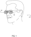
- FIG. 1 shows aspects of an example implementation environment for a near-eye display system 100.
- near-eye display system 100 is a component of a head-mounted electronic device 102, which is worn and operated by a user 104.
- the near-eye display system 100 is configured to present virtual imagery in the user's field of view.
- user-input componentry of the wearable electronic device 102 may enable the user to interact with the virtual imagery.
- the wearable electronic device 102 takes the form of eyeglasses in the example of FIG. 1 .
- the wearable electronic device 102 may take the form of goggles, a helmet, or a visor.
- the near-eye display system 100 may be a component of a non-wearable electronic device, such as a heads-up display.
- the near-eye display system 100 may be configured to cover one or both eyes of the user 104 and may be adapted for monocular or binocular image display. In examples in which the near-eye display system 100 covers only one eye, but binocular image display is desired, a complementary near-eye display system may be arranged over the other eye. In examples in which the near-eye display system covers both eyes and binocular image display is desired, the virtual imagery presented by near-eye display system 100 may be divided into right and left portions directed to the right and left eyes, respectively. In scenarios in which stereoscopic image display is desired, the virtual imagery from the right and left portions, or complementary near-eye display systems, may be configured with appropriate stereo disparity so as to present a three-dimensional subject or scene.
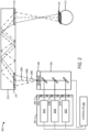
- FIG. 2 shows an example of the near-eye display system 200 that uses a laser assembly 202 as an illumination source.
- the laser assembly 202 includes lasers 202A (e.g., a red laser), 202B (e.g., a green laser), and 202C (e.g., a blue laser). Although only three lasers are shown, it will be appreciated that the laser assembly 202 may include any suitable number of lasers.
- the laser assembly 202 may include 0, 1, 2, 3, or more than 3 red lasers; 0, 1, 2, 3, or more than 3 green lasers; 0, 1, 2, 3, or more than 3 blue lasers; and 0, 1, 2, 3, or more than 3 lasers of other colors.
- any combination or modification in the number of lasers may also be available (e.g., 2 red, 2 green, 2 blue, or 1 red, 1 green, 2 blue, etc.). Accordingly, any number of lasers may be used to irradiate/illuminate pixels for generating image content.
- the laser assembly 202 also includes a collimating lens assembly 204 (or other diffractive optical element) that is structured to direct light to another location or otherwise operate on the light in some manner.
- a collimating lens assembly 204 or other diffractive optical element
- each of the lasers 202A, 202B, and 202C has a corresponding collimating lens 204A, 204B, 204C.
- a single collimating lens may be used for more than one laser.
- the near-eye display 200 includes combination optics 205 configured to spatially combine the light beams lased from the plurality of lasers 202A, 202B, and 202C into a single light beam.
- the near-eye display system 200 includes a micro-electro-mechanical mirror system (MEMs) 206, though the principles disclosed herein are applicable to any type of laser-based display unit and not only to architectures with the MEMs 206.
- the MEMs 206 is configured to collect laser light from the combination optics 205, which combines light lased from three different sources (i.e. the lasers 202A, 202B, and 202C). Additionally, the MEMs 206 is configured to direct laser light 208A (which, in this example includes red laser light, green laser light, and blue laser light) to a waveguide 210.
- laser light 208A which, in this example includes red laser light, green laser light, and blue laser light
- the MEMs 206 is configured to redirect its mirrors/mirror array so that the laser light 208A is aimed at different locations at the waveguide 210. As shown, laser lights 208B and 208C are aimed at different locations on the waveguide 210. In this manner, the MEMs 206 is able to route light to different locations by adjusting the aim of its corresponding mirror array. It will be appreciated that the laser lights 208A-C may be modulated to include varying degrees or intensities (or even an absence of any one or more) of red, green, blue, or other color laser light.
- the waveguide 210 is configured to redirect or propagate the laser light 208A-C to a desired location which is viewable by a user's eye 212. It will be appreciated that waveguide 210 may be any type of waveguide display (e.g., a surface relief grating waveguide).
- the laser light 208A-C enters the waveguide 210 via an entry grating 214.
- the laser light 208A-C then propagates (e.g., via total internal reflection) through the waveguide 210 until it reaches an exit grating 216.
- the angles with which the laser light 208A-C enters the waveguide 210 are preserved as the laser light 208A-C propagates through the waveguide 210. This condition is shown by the different angles that each of the respective laser lights 208A-C propagate through the waveguide 210.
- the MEMs 206 is able to use waveguide 210 to propagate light towards the user's eye 212.
- the laser assembly 202 and the MEMs 206 may be controlled by a controller 220.
- the controller 220 may be configured to control the MEMs 206, in conjunction with the laser assembly 202 to progressively scan a set of pixels 218 to a target display area for a user's eye 212 to view (e.g., by adjusting the mirror array so that the combined RGB laser beam or light is aimed at different locations) individual pixels of that image in such a rapid manner that the entirety of the image appears before the user's eye 212 without the user realizing that the image was progressively scanned pixel by pixel and line by line.
- the near-eye display system 200 may project or render image content for a user to view.
- the MEMs 206 may be able to scan an image (i.e., pixels of that image) at any image resolution or range of image resolutions (e.g., in cases where foveated rendering is used).
- the MEMs 206 is configured to scan RGB light from the laser assembly 202 with a resolution of 2,000 pixels by 1,200 pixels, or any other resolution.
- FIG. 3 shows an example image 300 including artifacts 302 and 304 caused by such fringe interference.
- the artifacts 302, 304 include irregularities in terms of brightness. The presence of such artifacts in an image can lower the perceived quality of the image and thereby negatively affect the user experience.
- the artifact 302 distorts the appearance of a dragon in the image 300.
- the artifact 304 distorts the appearance of a fireball shot by a wizard at the dragon in the image 300.
- a laser assembly may be configured to lase coherent light in a selected wavelength.
- the selected wavelength is rapidly tunable within a wavelength range via high-frequency modulation such that the laser may have a perceived increased bandwidth.
- a laser having an increased perceived laser bandwidth a larger number of wavelengths in the laser spectrum may interfere and the superposition of all the wavelengths may result in washing out the contrast of the fringe interference.
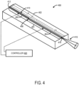
- FIG. 4 schematically shows an example laser assembly 400 configured to lase coherent light in a selected wavelength that is tunable within a wavelength range.
- the laser assembly 400 may be representative of any of the lasers 202A, 202B, 202C included in the near-eye display system 200 shown in FIG. 2 .
- the laser assembly 400 includes an optical cavity 401 positioned on a substrate 402.
- the optical cavity 401 includes an active gain section 404 and a reflector 406 section.
- the active gain section 404 may be optically coupled to the reflector section 406 via a transmissive interface 408.
- the active gain section 404 is edge coupled to the reflector section 406 via the transmissive interface 408.
- the transmissive interface 408 may be any suitable interface between the two sections of the optical cavity 401 that supports low coupling loss. It will be appreciated that the active gain section 404 may be optically coupled to the reflector section 406 in any suitable manner.
- the active gain section 404 is the source of optical gain within the laser assembly 400.
- the active gain section 404 is configured to amplify an optical power of light reflecting within the optical cavity across a wavelength range.
- the gain/amplification results from the stimulated emission of electronic or molecular transitions of an active gain medium of the active gain section 404 to a lower energy state from a higher energy state previously populated by a pump source.
- Laser pumping of the active gain section 404 may be performed using different pump sources, such as electrical currents or light generated by discharge lamps or by other lasers, for example.
- the active gain section 404 is configured as a reflective semiconductor optical amplifier (RSOA).
- RSOA reflective semiconductor optical amplifier
- the reflector section 406 may be configured to selectively reflect light of a selected wavelength within a wavelength range.
- the reflector section 406 may include a grating-based filter 410 to facilitate selective reflection across the wavelength range.
- the reflector section 406 may include any suitable grating-based filter.
- the grating-based filter 410 is a Distributed Bragg Grating (DBG).
- the DBG may be formed from multiple layers of alternating materials with varying refractive index, or by periodic variation of some characteristic (such as height) of a dielectric waveguide, resulting in periodic variation in the effective refractive index of the DBG. Each layer boundary causes a partial reflection of an optical wave. These partial reflections combine with constructive interference, such that the layers of the DBG act as a high-quality reflector.
- the DBG may be configured to reflect any suitable range of wavelengths.
- the reflector section 406 may include electro-optic material 412 that is configured to modulate a reflective index of the reflector section 406 as a function of a voltage of a waveform applied to the electro-optic material 412.
- the refractive index of the electro-optic material changes under the grating-based filter 410 which shifts the resonant frequency of the grating-based filter 410 to reflect different selected wavelengths of light within the wavelength range of the grating-based filter 410.
- the reflector section 406 may include any suitable electro-optic material. Non-limiting examples include crystalline electro-optic materials, polymer electro-optic materials, and organic electro-optic materials.
- the active gain section 404 includes a selectively reflective end 414.
- the reflector section 406 and the reflective end 414 may allow coherent light of a selected wavelength to reflect back and forth within the optical cavity. Each time a light beam passes through the active gain section, the optical power of the light beam may be amplified.
- the selectively reflective end 412 may be partially transparent to allow coherent light 416 to be output from the optical cavity 401.
- the optical cavity 401 has an overall length (L).
- the overall length (L) of the optical cavity 401 may satisfy fringe mitigation requirements while the power consumption is determined mainly by a length (LA) of the active gain section 404.
- the length (LA) of the active gain section 404 may be determined based on the laser requirement for the particular application.
- a length (LR) of the reflector section 406 can be selected, given a particular active section length, to provide an overall length (L) that avoids fringe optical path lengths (OPLs) that are imposed by a corresponding waveguide into which the laser assembly 400 lases coherent light.
- the length (LA) of the active gain section 404, the length (LR) of the reflector section 406, and/or the length (L) of the optical cavity 401 may be any suitable length.
- a controller 420 is electrically connected to the active gain section 404 and the reflector section 406.
- the controller 420 may be configured to control the laser assembly 400 to selectively lase coherent light in a selected wavelength within the wavelength range.
- the controller 420 may be configured to selectively apply a current to the active gain section 404 to cause the active gain section 404 to amplify the optical power of light in the optical cavity 401.
- the controller 420 may be further configured to modulate a voltage of a waveform applied to the reflector section 406 to tune the reflector section 406 to reflect a selected wavelength of coherent light such that coherent light in the selected wavelength may be lased from the optical cavity 401.
- the controller 420 may be configured to adjust the voltage to change the selected wavelength of coherent light lased by the optical cavity 401.
- FIG. 5 depicts an example gain spectrum 500 of the active gain section 404 and an example reflector loss spectrum 502 of the reflector section 406.
- the gain spectrum 500 includes a plurality of different wavelengths (e.g., ⁇ 1 , ⁇ 2 , ⁇ 3 ) at different mode locations within the gain spectrum 500.
- the heights of the different wavelengths in the gain spectrum 500 indicate an optical gain of light in that wavelength amplified by the active gain section 404.
- the reflector loss spectrum 502 includes a plurality of different wavelengths to which the reflector section 406 may be tuned to reflect light based on a corresponding voltage (e.g., V 1 , V 2 , V 3 ) being applied to the reflector section 406 by the controller 420.
- the controller 420 may apply voltage V l to the reflector section 406 to tune the reflector section 406 to reflect light having a wavelength ⁇ 1 .
- the controller 420 may apply voltage V 2 to the reflector section 406 to tune the reflector section 406 to reflect light having a wavelength ⁇ 2 .
- the controller 420 may apply voltage V 3 to the reflector section 406 to tune the reflector section 406 to reflect light having a wavelength ⁇ 3 .
- the reflector section 406 may be tuned such that a selected wavelength has a minimum loss (i.e., is reflected), and the gain at the selected wavelength becomes greater than the loss such that light at the selected wavelength is lased from the optical cavity 401.
- the controller 420 may be configured to modulate the refractive index of the reflector section 406 to reflect light at different wavelengths at a relatively high frequency. As one example, the controller 420 may be configured to switch the reflector section 406 between different wavelengths with a high enough frequency that the effective spectrum of coherent light lased from the laser assembly 400 would have a perceived bandwidth that is wider than any of the individual wavelengths. For example, as shown in FIG. 6 , the controller 420 may be configured to modulate the voltage of a waveform applied to the reflector section 406 to rapidly switch between reflecting light having wavelengths ⁇ 1 , ⁇ 2 , and ⁇ 3 .
- the controller 420 may be configured to modulate the voltage of a waveform applied to the reflector section 406 at a frequency suitably high enough to produce a time averaged lasing spectrum 600 of the plurality of different lasing spectra with a perceived bandwidth that is substantially wider than each of the individual spectra corresponding to ⁇ 1 , ⁇ 2 , and ⁇ 3 .
- the controller 420 may be configured to modulate the reflector section 406 to switch between reflecting light at different wavelengths at any suitable frequency.
- the controller 420 may be configured to modulate the voltage of a waveform applied to the reflector section 406 at least on a per pixel basis (e.g., rapidly switch between different wavelengths in less than one pixel time) for each of the plurality of pixels of the display.
- FIG. 7 show an example reflector modulation voltage drive scheme in which the controller 420 periodically modulates the voltage of a waveform applied to the reflector section 406 over two periods.
- a period is equivalent to twice a pixel time at which a pixel is scanned for a display (e.g., ⁇ 10 nanoseconds).
- the voltage is modulated as a triangle wave from a high voltage to a low voltage and back to the high voltage.
- FIG. 8 shows corresponding laser wavelength modulation over two periods based on the reflector modulation voltage drive scheme shown in FIG. 7 .
- the high voltage in the drive scheme corresponds to selecting a lasing central wavelength ⁇ 3 and the low voltage corresponds to selecting a lasing central wavelength ⁇ 1 .
- the lasing central wavelength can be modulated to have a perceived bandwidth between ⁇ 1 and ⁇ 3 which may be wider than any single wavelength spectra.
- the central wavelength is sinusoidally modulated. In other examples, the central wavelength may be differently modulated.
- the lasing central wavelength is modulated from ⁇ 3 to ⁇ 1 to have a perceived bandwidth between ⁇ 1 and ⁇ 3 for a first pixel.
- the lasing central wavelength is modulated from ⁇ 1 to ⁇ 3 to have a perceived bandwidth between ⁇ 1 and ⁇ 3 for a second pixel.
- the lasing central wavelength is modulated from ⁇ 3 to ⁇ 1 to have a perceived bandwidth between ⁇ 1 and ⁇ 3 for a third pixel. Then, still in P2, the lasing central wavelength is modulated from ⁇ 1 to ⁇ 3 to have a perceived bandwidth between ⁇ 1 and ⁇ 3 for a fourth pixel.
- Increasing the perceived laser bandwidth may address a variety of issues for a laser-based display. For example, increasing the laser bandwidth via high-frequency modulation may cause a large number of wavelengths in the laser spectrum to interfere and the superposition of all the wavelengths may result in a washout of contrast for interference fringes. In this way, fringe interference artifacts in images presented by such a laser-based display may be reduced. As another example, increasing the laser bandwidth may cause light inside a waveguide to couple out at a larger range of angles causing overlap of different wavelengths that blur out FOV boundaries. In this way, image quality of images presented by such a laser-based display may be improved.
- FIG. 9 shows an example method 900 for operating an edge-emitting laser, such as the laser assemblies 202 and 400 shown in FIGS. 2 and 4 .
- the method 900 may be performed by the near-eye display system 100 shown in FIG. 1 , and/or the controller 220 shown in FIG. 2 .
- the method 900 includes applying a waveform having a first voltage to a reflector section of an optical cavity of the edge-emitting laser to tune the reflector section to reflect coherent light having a first wavelength.
- the reflector section may be configured to selectively reflect light of a selected wavelength, wherein the selected wavelength is tunable via high-frequency index modulation of the reflector section.
- the method 900 includes exciting an active gain section of the optical cavity of the edge-emitting laser to lase coherent light having the first wavelength.
- the method 900 includes applying a waveform having a second voltage, different than the first voltage, to the reflector section to tune the reflector section to reflect coherent light having a second wavelength different than the first wavelength.
- the method 900 includes exciting the active gain section to lase coherent light having the second wavelength.
- the method 900 may be repeatedly performed. In some implementations, the method 900 may be repeatedly performed at a frequency suitably high enough to widen a perceived bandwidth of the coherent light lased from the edge-emitting laser. In some implementations wherein the edge-emitting laser is configured to lase the coherent light to a display including a plurality of pixels, the method 900 may be repeatedly performed at a frequency that is at least on a per pixel basis to lase coherent light to each of the plurality of pixels of the display.
- FIG. 10 schematically shows a simplified representation of a computing system 1000 configured to provide any to all of the compute functionality described herein.
- Computing system 1000 may take the form of one or more head-mounted, near-eye display devices, personal computers, network-accessible server computers, tablet computers, home-entertainment computers, gaming devices, mobile computing devices, mobile communication devices (e.g., smart phone), virtual/augmented/mixed reality computing devices, wearable computing devices, Internet of Things (IoT) devices, embedded computing devices, and/or other computing devices.
- computing system 1000 may be representative of the head-mounted electronic device 102 in FIG. 1 .
- Computing system 1000 includes a logic subsystem 1002 and a storage subsystem 1004 Computing system 1000 may optionally include a display subsystem 1006, input subsystem 1008, communication subsystem 1010, and/or other subsystems not shown in FIG. 10 .
- Logic subsystem 1002 includes one or more physical devices configured to execute instructions.
- the logic subsystem 1002 may be configured to execute instructions that are part of one or more applications, services, or other logical constructs.
- the logic subsystem 1002 may include one or more hardware processors configured to execute software instructions. Additionally or alternatively, the logic subsystem 1002 may include one or more hardware or firmware devices configured to execute hardware or firmware instructions.
- Processors of the logic subsystem 1002 may be single-core or multicore, and the instructions executed thereon may be configured for sequential, parallel, and/or distributed processing. Individual components of the logic subsystem 1002 optionally may be distributed among two or more separate devices, which may be remotely located and/or configured for coordinated processing. Aspects of the logic subsystem 1002 may be virtualized and executed by remotely-accessible, networked computing devices configured in a cloud-computing configuration.
- Storage subsystem 1004 includes one or more physical devices configured to temporarily and/or permanently hold computer information such as data and instructions executable by the logic subsystem 1002. When the storage subsystem 1004 includes two or more devices, the devices may be collocated and/or remotely located. Storage subsystem 1004 may include volatile, nonvolatile, dynamic, static, read/write, read-only, random-access, sequential-access, location-addressable, file-addressable, and/or content-addressable devices. Storage subsystem 1004 may include removable and/or built-in devices. When the logic subsystem 1002 executes instructions, the state of storage subsystem 1004 may be transformed - e.g., to hold different data.
- logic subsystem 1002 and storage subsystem 1004 may be integrated together into one or more hardware-logic components.
- Such hardware-logic components may include program- and application-specific integrated circuits (PASIC / ASICs), program- and application-specific standard products (PSSP / ASSPs), system-on-a-chip (SOC), and complex programmable logic devices (CPLDs), for example.
- PASIC / ASICs program- and application-specific integrated circuits
- PSSP / ASSPs program- and application-specific standard products
- SOC system-on-a-chip
- CPLDs complex programmable logic devices
- the logic subsystem 1002 and the storage subsystem 1004 may cooperate to instantiate one or more logic machines.
- the term "machine” is used to collectively refer to the combination of hardware, firmware, software, instructions, and/or any other components cooperating to provide computer functionality. In other words, "machines" are never abstract ideas and always have a tangible form.
- a machine may be instantiated by a single computing device, or a machine may include two or more subcomponents instantiated by two or more different computing devices.
- a machine includes a local component (e.g., software application executed by a computer processor) cooperating with a remote component (e.g., cloud computing service provided by a network of server computers).
- the software and/or other instructions that give a particular machine its functionality may optionally be saved as one or more unexecuted modules on one or more suitable storage devices.
- the logic subsystem 1002 and the storage subsystem 1004 may be implemented as a controller, such as controller 220 shown in FIGS. 2 and 4 .
- display subsystem 1006 may be used to present a visual representation of data held by storage subsystem 1004. This visual representation may take the form of a graphical user interface (GUI).
- GUI graphical user interface
- Display subsystem 1006 may include one or more display devices utilizing virtually any type of technology.
- display subsystem may include one or more virtual-, augmented-, or mixed reality displays.
- display subsystem 1006 may be implemented as the near-eye display system 100 shown in FIG. 1 and/or the near-eye display system 200 shown in FIG. 2 .
- input subsystem 1008 may comprise or interface with one or more input devices.
- An input device may include a sensor device or a user input device. Examples of user input devices include a keyboard, mouse, touch screen, or game controller.
- the input subsystem may comprise or interface with selected natural user input (NUI) componentry. Such componentry may be integrated or peripheral, and the transduction and/or processing of input actions may be handled on- or off-board.
- NUI componentry may include a microphone for speech and/or voice recognition; an infrared, color, stereoscopic, and/or depth camera for machine vision and/or gesture recognition; a head tracker, eye tracker, accelerometer, and/or gyroscope for motion detection and/or intent recognition.
- communication subsystem 1010 may be configured to communicatively couple computing system 1000 with one or more other computing devices.
- Communication subsystem 1010 may include wired and/or wireless communication devices compatible with one or more different communication protocols.
- the communication subsystem 1010 may be configured for communication via personal-, local- and/or wide-area networks.
- edge-emitting laser comprises an active gain section configured to amplify an optical power of light across a wavelength range, and a reflector section optically coupled to the active gain section and configured to selectively reflect light of a selected wavelength within the wavelength range, wherein the selected wavelength is tunable via high-frequency index modulation of the reflector section, wherein the active gain section and the reflector section collectively form an optical cavity configured to lase coherent light in the selected wavelength.
- the reflector section may include a grating-based filter.
- the grating-based filter may be a Distributed Bragg Reflector.
- the reflector section may include electro-optic material configured to modulate a reflective index of the reflector section as a function of a voltage of a waveform applied to the electro-optic material.
- the edge-emitting laser may further comprise a controller configured to modulate a voltage of a waveform applied to the reflector section to tune the selected wavelength of the coherent light lased by the optical cavity.
- the controller may be configured to periodically modulate the voltage of the waveform applied to the reflector section.
- the controller may be configured to modulate the voltage of the waveform applied to the reflector section to sinusoidally modulate the selected wavelength within the wavelength range.
- the edge-emitting laser may be configured to lase the coherent light to a display including a plurality of pixels, and the controller may be configured to modulate the voltage of the waveform applied to the reflector section at least on a per pixel basis for the plurality of pixels of the display. In this example and/or other examples, the controller may be configured to modulate the voltage of the waveform applied to the reflector section at a frequency suitably high enough to widen a perceived bandwidth of the coherent light. In this example and/or other examples, the edge-emitting laser may be configured to lase coherent light into a waveguide, and the controller may be configured to tune the perceived bandwidth of the coherent light to reduce fringe interference due to the coherent light propagating through the waveguide.
- an edge-emitting laser comprises an active gain section configured to amplify an optical power of light across a wavelength range, and a reflector section optically coupled to the active gain section and configured to selectively reflect light of a selected wavelength within the wavelength range, wherein the selected wavelength is tunable via high-frequency index modulation of the reflector section, wherein the active gain section and the reflector section collectively form an optical cavity configured to lase coherent light in the selected wavelength, and a controller configured to modulate a voltage of a waveform applied to the reflector section to tune the selected wavelength of the coherent light lased by the optical cavity.
- the controller may be configured to periodically modulate the voltage of the waveform applied to the reflector section.
- the controller may be configured to modulate the voltage of the waveform applied to the reflector section to sinusoidally modulate the selected wavelength within the wavelength range.
- the edge-emitting laser may be configured to lase the coherent light to a display including a plurality of pixels, and the controller may be configured to modulate the voltage of the waveform applied to the reflector section at least on a per pixel basis for the plurality of pixels of the display.
- the controller may be configured to modulate the voltage of the waveform applied to the reflector section at a frequency suitably high enough to widen a perceived bandwidth of the coherent light.
- the edge-emitting laser may be configured to lase coherent light into a waveguide, and the controller may be configured to tune a perceived bandwidth of the coherent light to reduce fringe interference due to the coherent light propagating through the waveguide.
- a method for operating an edge-emitting laser having an optical cavity including an active gain section and a reflector section configured to selectively reflect light of a selected wavelength tunable via high-frequency index modulation of the reflector section comprises applying a waveform having a first voltage to the reflector section to tune the reflector section to reflect coherent light having a first wavelength, exciting the active gain section to lase coherent light having the first wavelength, applying a waveform having a second voltage, different than the first voltage, to the reflector section to tune the reflector section to reflect coherent light having a second wavelength different than the first wavelength, and exciting the active gain section to lase coherent light having the second wavelength.
- the reflector section may be tuned periodically between reflecting coherent light having the first wavelength and reflecting coherent light having the second wavelength. In this example and/or other examples, the reflector section may be tuned between reflecting coherent light having the first wavelength and reflecting coherent light having the second wavelength at a frequency suitably high enough to widen a perceived bandwidth of the coherent light.
- the edge-emitting laser may be configured to lase the coherent light to a display including a plurality of pixels, and the reflector section may be tuned between reflecting coherent light having the first wavelength and reflecting coherent light having the second wavelength at least on a per pixel basis for the plurality of pixels of the display.
Landscapes
- Physics & Mathematics (AREA)
- General Physics & Mathematics (AREA)
- Optics & Photonics (AREA)
- Condensed Matter Physics & Semiconductors (AREA)
- Electromagnetism (AREA)
- Acoustics & Sound (AREA)
- Control Of Indicators Other Than Cathode Ray Tubes (AREA)
- Optical Modulation, Optical Deflection, Nonlinear Optics, Optical Demodulation, Optical Logic Elements (AREA)
- Lasers (AREA)
Claims (10)
- Kantenemittierender Laser (202; 400), der mit einem Wellenleiter (210) und mit einer Anzeige, die eine Vielzahl von Pixeln (218) beinhaltet, verbunden werden kann, wobei der kantenemittierende Laser (202) Folgendes umfasst:einen aktiven Verstärkungsabschnitt (404), der so konfiguriert ist, dass er eine optische Leistung von Licht über einen Wellenlängenbereich verstärkt;einen Reflektorabschnitt (406), der optisch mit dem aktiven Verstärkungsabschnitt (404) gekoppelt ist und so konfiguriert ist, dass er selektiv Licht einer ausgewählten Wellenlänge innerhalb des Wellenlängenbereichs reflektiert, wobei die ausgewählte Wellenlänge über eine Hochfrequenz-Indexmodulation des Reflektorabschnitts (406) abstimmbar ist,wobei der aktive Verstärkungsabschnitt (404) und der Reflektorabschnitt (406) zusammen einen optischen Resonator (401) bilden, der so konfiguriert ist, dass er kohärentes Licht mit der ausgewählten Wellenlänge in den Wellenleiter (210) und zur Anzeige lasert; undeine Steuerung (420), die so konfiguriert ist, dass sie eine Spannung einer Wellenform moduliert, die auf den Reflektorabschnitt (406) angewendet wird, um die ausgewählte Wellenlänge des kohärenten Lichts, das durch den optischen Resonator (401) gelasert wird, zwischen einer Vielzahl von verschiedenen Laserspektren bei einer Frequenz abzustimmen, um ein zeitlich gemitteltes Laserspektrum (600) der Vielzahl unterschiedlicher Laserspektren an jedem Pixel (218) mit einer Bandbreite zu erzeugen, die breiter ist als jedes der einzelnen unterschiedlichen Laserspektren, sodass die Streifeninterferenz aufgrund des kohärenten Lichts, das sich durch den Wellenleiter (210) verbreitet, verringert wird.
- Kantenemittierender Laser (202; 400) nach Anspruch 1, wobei der Reflektorabschnitt (406) einen gitterbasierten Filter (410) beinhaltet.
- Kantenemittierender Laser (202; 400) nach Anspruch 2, wobei der gitterbasierte Filter (410) ein Distributed-Bragg-Reflektor ist.
- Kantenemittierender Laser (202; 400) nach Anspruch 1, wobei der Reflektorabschnitt (406) elektrooptisches Material (412) beinhaltet, das so konfiguriert ist, dass es einen Reflexionsindex des Reflektorabschnitts (406) als Funktion einer Spannung einer Wellenform moduliert, die auf das elektrooptische Material (412) angewendet wird.
- Kantenemittierender Laser (202; 400) nach Anspruch 1, wobei die Steuerung (420) so konfiguriert ist, dass sie die Spannung der Wellenform, die auf den Reflektorabschnitt (406) angewendet wird, periodisch moduliert.
- Kantenemittierender Laser (202; 400) nach Anspruch 1, wobei die Steuerung (420) so konfiguriert ist, dass sie die Spannung der Wellenform moduliert, die auf den Reflektorabschnitt (406) angewendet wird, um die ausgewählte Wellenlänge innerhalb des Wellenlängenbereichs sinusförmig zu modulieren.
- Kantenemittierender Laser nach Anspruch 1, wobei die Steuerung (420) so konfiguriert ist, dass sie die Spannung der Wellenform, die auf den Reflektorabschnitt (406) angewendet wird, mit einer Frequenz moduliert, die geeignet hoch genug ist, um die Bandbreite des kohärenten Lichts zu verbreitern.
- Verfahren (900) zum Betreiben eines kantenemittierenden Lasers (202; 400), der so konfiguriert ist, dass er mit einem Wellenleiter (210) und einer Anzeige, die eine Vielzahl von Pixeln (218) beinhaltet, verbunden werden kann, wobei der kantenemittierende Laser (202; 400) einen optischen Resonator (401) aufweist, der einen aktiven Verstärkungsabschnitt (404) und einen Reflektorabschnitt (406) beinhaltet, der so konfiguriert ist, dass er selektiv Licht einer ausgewählten Wellenlänge reflektiert, das über eine Hochfrequenz-Indexmodulation des Reflektorabschnitts (406) abstimmbar ist, wobei das Verfahren umfasst:Anwenden (902) einer Wellenform, die eine erste Spannung aufweist, auf den Reflektorabschnitt (406), um den Reflektorabschnitt (406) so abzustimmen, dass er kohärentes Licht mit einer ersten Wellenlänge reflektiert;Anregen (904) des aktiven Verstärkungsabschnitts (404), der so konfiguriert ist, dass er kohärentes Licht mit der ersten Wellenlänge in den Wellenleiter (210) und zur Anzeige lasert;Anwenden (906) einer Wellenform mit einer zweiten Spannung, die sich von der ersten Spannung unterscheidet, auf den Reflektorabschnitt (406), um den Reflektorabschnitt (406) so abzustimmen, dass er kohärentes Licht mit einer zweiten Wellenlänge, die sich von der ersten Wellenlänge unterscheidet, reflektiert; undAnregen (908) des aktiven Verstärkungsabschnitts, der so konfiguriert ist, dass er kohärentes Licht mit der zweiten Wellenlänge in den Wellenleiter (210) und zur Anzeige lasert,wobei der Reflektorabschnitt (406) zwischen der Reflexion von kohärentem Licht mit der ersten Wellenlänge und der Reflexion von kohärentem Licht mit der zweiten Wellenlänge, abgestimmt ist, um ein zeitlich gemitteltes Laserspektrum (600) an jedem Pixel (218) mit einer Bandbreite zu erzeugen, die breiter ist als jede der ersten und zweiten Wellenlänge, so dass die Streifeninterferenz aufgrund des kohärenten Lichts, das sich durch den Wellenleiter (210) verbreitet, verringert wird.
- Verfahren nach Anspruch 8, wobei der Reflektorabschnitt (406) periodisch zwischen der Reflexion von kohärentem Licht mit der ersten Wellenlänge und der Reflexion von kohärentem Licht mit der zweiten Wellenlänge abgestimmt wird.
- Verfahren nach Anspruch 8, wobei der Reflektorabschnitt (406) zwischen der Reflexion von kohärentem Licht mit der ersten Wellenlänge und der Reflexion von kohärentem Licht mit der zweiten Wellenlänge bei einer Frequenz abgestimmt wird, die geeignet hoch genug ist, um die Bandbreite des kohärenten Lichts zu verbreitern.
Applications Claiming Priority (2)
| Application Number | Priority Date | Filing Date | Title |
|---|---|---|---|
| US16/417,439 US10958038B2 (en) | 2019-05-20 | 2019-05-20 | Edge-emitting laser with high-frequency modulated reflector section |
| PCT/US2020/028021 WO2020236342A1 (en) | 2019-05-20 | 2020-04-14 | Edge-emitting laser with high-frequency modulated reflector section |
Publications (2)
| Publication Number | Publication Date |
|---|---|
| EP3973601A1 EP3973601A1 (de) | 2022-03-30 |
| EP3973601B1 true EP3973601B1 (de) | 2024-12-04 |
Family
ID=70482884
Family Applications (1)
| Application Number | Title | Priority Date | Filing Date |
|---|---|---|---|
| EP20723711.6A Active EP3973601B1 (de) | 2019-05-20 | 2020-04-14 | Kantenemittierender laser mit hochfrequenzmoduliertem reflektorabschnitt |
Country Status (3)
| Country | Link |
|---|---|
| US (1) | US10958038B2 (de) |
| EP (1) | EP3973601B1 (de) |
| WO (1) | WO2020236342A1 (de) |
Families Citing this family (5)
| Publication number | Priority date | Publication date | Assignee | Title |
|---|---|---|---|---|
| FI20215616A1 (en) * | 2021-05-25 | 2022-11-26 | Dispelix Oy | An optical waveguide arrangement for reducing interference patterns |
| US12266904B2 (en) * | 2021-06-02 | 2025-04-01 | Microsoft Technology Licensing, Llc | Modulator integration for laser used with display |
| US11899211B2 (en) * | 2021-06-24 | 2024-02-13 | Microsoft Technology Licensing, Llc | Pulse-modulated laser-based near-eye display |
| US11656467B2 (en) | 2021-06-24 | 2023-05-23 | Microsoft Technology Licensing, Llc | Compact laser-based near-eye display |
| US11984700B2 (en) * | 2022-10-05 | 2024-05-14 | Microsoft Technology Licensing, Llc | Integrated laser and modulator systems |
Citations (1)
| Publication number | Priority date | Publication date | Assignee | Title |
|---|---|---|---|---|
| WO2017218245A1 (en) * | 2016-06-13 | 2017-12-21 | Microsoft Technology Licensing, Llc | Avoiding interference by reducing spatial coherence in a near-eye display |
Family Cites Families (15)
| Publication number | Priority date | Publication date | Assignee | Title |
|---|---|---|---|---|
| US5418802A (en) * | 1993-11-12 | 1995-05-23 | Eastman Kodak Company | Frequency tunable waveguide extended cavity laser |
| US20020093995A1 (en) * | 1995-09-29 | 2002-07-18 | Parviz Tayebati | Electro-optically tunable external cavity mirror for a narrow linewidth semiconductor laser |
| US6480513B1 (en) * | 2000-10-03 | 2002-11-12 | K2 Optronics, Inc. | Tunable external cavity laser |
| US20030002138A1 (en) * | 2001-06-27 | 2003-01-02 | International Business Machines Corporation | Gain stabilized raman effect optical amplifiers for coarse and dense wavelength multiplexers |
| US8068115B2 (en) * | 2003-05-19 | 2011-11-29 | Microvision, Inc. | Image generation with interpolation and distortion correction |
| JP5231990B2 (ja) | 2006-03-03 | 2013-07-10 | パナソニック株式会社 | 照明光源及びレーザ投射装置 |
| US8223161B2 (en) * | 2007-08-22 | 2012-07-17 | Microvision, Inc. | Electronic alignment of primary color pixels in a scanned display |
| US7715453B2 (en) * | 2007-11-20 | 2010-05-11 | Corning Incorporated | Wavelength control in phase region of semiconductor lasers |
| US7970028B2 (en) | 2008-01-30 | 2011-06-28 | Corning Incorporated | System and methods for speckle reduction |
| US20100232005A1 (en) * | 2009-03-12 | 2010-09-16 | Microvision, Inc. | Speckle Reduction in Display Systems Using Transverse Phase Modulation in A Non-Image Plane |
| US8585206B2 (en) | 2010-06-29 | 2013-11-19 | Corning Incorporated | Methods for operating scanning laser projectors to reduce speckle and image flicker |
| GB2493989A (en) | 2011-08-26 | 2013-02-27 | Oclaro Technology Ltd | Tunable multi-mode laser |
| US10025089B2 (en) * | 2012-10-05 | 2018-07-17 | Microsoft Technology Licensing, Llc | Backlight for viewing three-dimensional images from a display from variable viewing angles |
| GB2522410B (en) * | 2014-01-20 | 2020-10-07 | Rockley Photonics Ltd | Tunable Silicon-On-Insulator (SOI) Laser |
| US10394034B2 (en) | 2017-08-15 | 2019-08-27 | Microsoft Technology Licensing, Llc | Eye-tracking with MEMS scanning and optical relay |
-
2019
- 2019-05-20 US US16/417,439 patent/US10958038B2/en active Active
-
2020
- 2020-04-14 EP EP20723711.6A patent/EP3973601B1/de active Active
- 2020-04-14 WO PCT/US2020/028021 patent/WO2020236342A1/en not_active Ceased
Patent Citations (1)
| Publication number | Priority date | Publication date | Assignee | Title |
|---|---|---|---|---|
| WO2017218245A1 (en) * | 2016-06-13 | 2017-12-21 | Microsoft Technology Licensing, Llc | Avoiding interference by reducing spatial coherence in a near-eye display |
Also Published As
| Publication number | Publication date |
|---|---|
| US10958038B2 (en) | 2021-03-23 |
| WO2020236342A1 (en) | 2020-11-26 |
| US20200373734A1 (en) | 2020-11-26 |
| EP3973601A1 (de) | 2022-03-30 |
Similar Documents
| Publication | Publication Date | Title |
|---|---|---|
| EP3973601B1 (de) | Kantenemittierender laser mit hochfrequenzmoduliertem reflektorabschnitt | |
| US20210281047A1 (en) | Broadened spectrum laser diode for display device | |
| US10770865B1 (en) | Multi-stripe edge-emitting laser | |
| EP3970247B1 (de) | Zweiteiliger kantenemittierender laser | |
| US11640054B2 (en) | Multi-wavelength self-mixing interferometry | |
| JP2024531953A (ja) | レーザベースシステム用のフレネル反射ベースの光ピックオフ要素 | |
| US12181671B2 (en) | Systems, devices, and methods for inputting light from a scanning projector into a waveguide | |
| US11656467B2 (en) | Compact laser-based near-eye display | |
| US11899211B2 (en) | Pulse-modulated laser-based near-eye display | |
| US12132296B2 (en) | Laser having reduced coherence via a phaser shifter | |
| US12313855B2 (en) | Systems and methods to separate scanning mirror input and output light | |
| US12266904B2 (en) | Modulator integration for laser used with display | |
| WO2022271329A1 (en) | Spectrally diverse laser-based near-eye display | |
| US12547002B2 (en) | Utilizing a visible light filter to reduce visibility of fiducial images | |
| EP4597297A1 (de) | Temperaturbasierte dynamische laserabstimmung zur förderung der anzeigegleichförmigkeit | |
| US12265230B2 (en) | Multiple laser light source sets for scanning display systems | |
| WO2024005931A1 (en) | Passive world-referenced display alignment with reflective facet lightguides |
Legal Events
| Date | Code | Title | Description |
|---|---|---|---|
| STAA | Information on the status of an ep patent application or granted ep patent |
Free format text: STATUS: UNKNOWN |
|
| STAA | Information on the status of an ep patent application or granted ep patent |
Free format text: STATUS: THE INTERNATIONAL PUBLICATION HAS BEEN MADE |
|
| PUAI | Public reference made under article 153(3) epc to a published international application that has entered the european phase |
Free format text: ORIGINAL CODE: 0009012 |
|
| STAA | Information on the status of an ep patent application or granted ep patent |
Free format text: STATUS: REQUEST FOR EXAMINATION WAS MADE |
|
| 17P | Request for examination filed |
Effective date: 20211001 |
|
| AK | Designated contracting states |
Kind code of ref document: A1 Designated state(s): AL AT BE BG CH CY CZ DE DK EE ES FI FR GB GR HR HU IE IS IT LI LT LU LV MC MK MT NL NO PL PT RO RS SE SI SK SM TR |
|
| DAV | Request for validation of the european patent (deleted) | ||
| DAX | Request for extension of the european patent (deleted) | ||
| GRAP | Despatch of communication of intention to grant a patent |
Free format text: ORIGINAL CODE: EPIDOSNIGR1 |
|
| STAA | Information on the status of an ep patent application or granted ep patent |
Free format text: STATUS: GRANT OF PATENT IS INTENDED |
|
| RIC1 | Information provided on ipc code assigned before grant |
Ipc: H01S 5/0225 20210101ALI20240610BHEP Ipc: G02B 27/48 20060101ALI20240610BHEP Ipc: G02B 27/01 20060101ALI20240610BHEP Ipc: H01S 5/065 20060101ALI20240610BHEP Ipc: H01S 5/125 20060101ALI20240610BHEP Ipc: H01S 5/0625 20060101ALI20240610BHEP Ipc: H04N 9/31 20060101ALI20240610BHEP Ipc: H01S 5/10 20210101ALI20240610BHEP Ipc: H01S 5/40 20060101ALI20240610BHEP Ipc: H01S 5/022 20210101AFI20240610BHEP |
|
| INTG | Intention to grant announced |
Effective date: 20240626 |
|
| GRAS | Grant fee paid |
Free format text: ORIGINAL CODE: EPIDOSNIGR3 |
|
| GRAA | (expected) grant |
Free format text: ORIGINAL CODE: 0009210 |
|
| STAA | Information on the status of an ep patent application or granted ep patent |
Free format text: STATUS: THE PATENT HAS BEEN GRANTED |
|
| P01 | Opt-out of the competence of the unified patent court (upc) registered |
Free format text: CASE NUMBER: APP_57901/2024 Effective date: 20241023 |
|
| AK | Designated contracting states |
Kind code of ref document: B1 Designated state(s): AL AT BE BG CH CY CZ DE DK EE ES FI FR GB GR HR HU IE IS IT LI LT LU LV MC MK MT NL NO PL PT RO RS SE SI SK SM TR |
|
| REG | Reference to a national code |
Ref country code: CH Ref legal event code: EP |
|
| REG | Reference to a national code |
Ref country code: DE Ref legal event code: R096 Ref document number: 602020042464 Country of ref document: DE |
|
| REG | Reference to a national code |
Ref country code: IE Ref legal event code: FG4D |
|
| REG | Reference to a national code |
Ref country code: LT Ref legal event code: MG9D |
|
| REG | Reference to a national code |
Ref country code: NL Ref legal event code: MP Effective date: 20241204 |
|
| PG25 | Lapsed in a contracting state [announced via postgrant information from national office to epo] |
Ref country code: HR Free format text: LAPSE BECAUSE OF FAILURE TO SUBMIT A TRANSLATION OF THE DESCRIPTION OR TO PAY THE FEE WITHIN THE PRESCRIBED TIME-LIMIT Effective date: 20241204 |
|
| PG25 | Lapsed in a contracting state [announced via postgrant information from national office to epo] |
Ref country code: FI Free format text: LAPSE BECAUSE OF FAILURE TO SUBMIT A TRANSLATION OF THE DESCRIPTION OR TO PAY THE FEE WITHIN THE PRESCRIBED TIME-LIMIT Effective date: 20241204 |
|
| PG25 | Lapsed in a contracting state [announced via postgrant information from national office to epo] |
Ref country code: BG Free format text: LAPSE BECAUSE OF FAILURE TO SUBMIT A TRANSLATION OF THE DESCRIPTION OR TO PAY THE FEE WITHIN THE PRESCRIBED TIME-LIMIT Effective date: 20241204 |
|
| PG25 | Lapsed in a contracting state [announced via postgrant information from national office to epo] |
Ref country code: ES Free format text: LAPSE BECAUSE OF FAILURE TO SUBMIT A TRANSLATION OF THE DESCRIPTION OR TO PAY THE FEE WITHIN THE PRESCRIBED TIME-LIMIT Effective date: 20241204 |
|
| PG25 | Lapsed in a contracting state [announced via postgrant information from national office to epo] |
Ref country code: NO Free format text: LAPSE BECAUSE OF FAILURE TO SUBMIT A TRANSLATION OF THE DESCRIPTION OR TO PAY THE FEE WITHIN THE PRESCRIBED TIME-LIMIT Effective date: 20250304 |
|
| PG25 | Lapsed in a contracting state [announced via postgrant information from national office to epo] |
Ref country code: LV Free format text: LAPSE BECAUSE OF FAILURE TO SUBMIT A TRANSLATION OF THE DESCRIPTION OR TO PAY THE FEE WITHIN THE PRESCRIBED TIME-LIMIT Effective date: 20241204 Ref country code: GR Free format text: LAPSE BECAUSE OF FAILURE TO SUBMIT A TRANSLATION OF THE DESCRIPTION OR TO PAY THE FEE WITHIN THE PRESCRIBED TIME-LIMIT Effective date: 20250305 |
|
| PGFP | Annual fee paid to national office [announced via postgrant information from national office to epo] |
Ref country code: GB Payment date: 20250319 Year of fee payment: 6 |
|
| PG25 | Lapsed in a contracting state [announced via postgrant information from national office to epo] |
Ref country code: RS Free format text: LAPSE BECAUSE OF FAILURE TO SUBMIT A TRANSLATION OF THE DESCRIPTION OR TO PAY THE FEE WITHIN THE PRESCRIBED TIME-LIMIT Effective date: 20250304 |
|
| PG25 | Lapsed in a contracting state [announced via postgrant information from national office to epo] |
Ref country code: NL Free format text: LAPSE BECAUSE OF FAILURE TO SUBMIT A TRANSLATION OF THE DESCRIPTION OR TO PAY THE FEE WITHIN THE PRESCRIBED TIME-LIMIT Effective date: 20241204 |
|
| REG | Reference to a national code |
Ref country code: AT Ref legal event code: MK05 Ref document number: 1749182 Country of ref document: AT Kind code of ref document: T Effective date: 20241204 |
|
| PG25 | Lapsed in a contracting state [announced via postgrant information from national office to epo] |
Ref country code: SM Free format text: LAPSE BECAUSE OF FAILURE TO SUBMIT A TRANSLATION OF THE DESCRIPTION OR TO PAY THE FEE WITHIN THE PRESCRIBED TIME-LIMIT Effective date: 20241204 |
|
| PG25 | Lapsed in a contracting state [announced via postgrant information from national office to epo] |
Ref country code: PL Free format text: LAPSE BECAUSE OF FAILURE TO SUBMIT A TRANSLATION OF THE DESCRIPTION OR TO PAY THE FEE WITHIN THE PRESCRIBED TIME-LIMIT Effective date: 20241204 |
|
| PGFP | Annual fee paid to national office [announced via postgrant information from national office to epo] |
Ref country code: DE Payment date: 20250319 Year of fee payment: 6 |
|
| PG25 | Lapsed in a contracting state [announced via postgrant information from national office to epo] |
Ref country code: IS Free format text: LAPSE BECAUSE OF FAILURE TO SUBMIT A TRANSLATION OF THE DESCRIPTION OR TO PAY THE FEE WITHIN THE PRESCRIBED TIME-LIMIT Effective date: 20250404 |
|
| PG25 | Lapsed in a contracting state [announced via postgrant information from national office to epo] |
Ref country code: PT Free format text: LAPSE BECAUSE OF FAILURE TO SUBMIT A TRANSLATION OF THE DESCRIPTION OR TO PAY THE FEE WITHIN THE PRESCRIBED TIME-LIMIT Effective date: 20250404 |
|
| PG25 | Lapsed in a contracting state [announced via postgrant information from national office to epo] |
Ref country code: EE Free format text: LAPSE BECAUSE OF FAILURE TO SUBMIT A TRANSLATION OF THE DESCRIPTION OR TO PAY THE FEE WITHIN THE PRESCRIBED TIME-LIMIT Effective date: 20241204 |
|
| PG25 | Lapsed in a contracting state [announced via postgrant information from national office to epo] |
Ref country code: AT Free format text: LAPSE BECAUSE OF FAILURE TO SUBMIT A TRANSLATION OF THE DESCRIPTION OR TO PAY THE FEE WITHIN THE PRESCRIBED TIME-LIMIT Effective date: 20241204 Ref country code: RO Free format text: LAPSE BECAUSE OF FAILURE TO SUBMIT A TRANSLATION OF THE DESCRIPTION OR TO PAY THE FEE WITHIN THE PRESCRIBED TIME-LIMIT Effective date: 20241204 |
|
| PG25 | Lapsed in a contracting state [announced via postgrant information from national office to epo] |
Ref country code: SK Free format text: LAPSE BECAUSE OF FAILURE TO SUBMIT A TRANSLATION OF THE DESCRIPTION OR TO PAY THE FEE WITHIN THE PRESCRIBED TIME-LIMIT Effective date: 20241204 |
|
| PG25 | Lapsed in a contracting state [announced via postgrant information from national office to epo] |
Ref country code: CZ Free format text: LAPSE BECAUSE OF FAILURE TO SUBMIT A TRANSLATION OF THE DESCRIPTION OR TO PAY THE FEE WITHIN THE PRESCRIBED TIME-LIMIT Effective date: 20241204 |
|
| PG25 | Lapsed in a contracting state [announced via postgrant information from national office to epo] |
Ref country code: IT Free format text: LAPSE BECAUSE OF FAILURE TO SUBMIT A TRANSLATION OF THE DESCRIPTION OR TO PAY THE FEE WITHIN THE PRESCRIBED TIME-LIMIT Effective date: 20241204 |
|
| REG | Reference to a national code |
Ref country code: DE Ref legal event code: R097 Ref document number: 602020042464 Country of ref document: DE |
|
| PG25 | Lapsed in a contracting state [announced via postgrant information from national office to epo] |
Ref country code: SE Free format text: LAPSE BECAUSE OF FAILURE TO SUBMIT A TRANSLATION OF THE DESCRIPTION OR TO PAY THE FEE WITHIN THE PRESCRIBED TIME-LIMIT Effective date: 20241204 |
|
| PG25 | Lapsed in a contracting state [announced via postgrant information from national office to epo] |
Ref country code: DK Free format text: LAPSE BECAUSE OF FAILURE TO SUBMIT A TRANSLATION OF THE DESCRIPTION OR TO PAY THE FEE WITHIN THE PRESCRIBED TIME-LIMIT Effective date: 20241204 |
|
| PLBE | No opposition filed within time limit |
Free format text: ORIGINAL CODE: 0009261 |
|
| STAA | Information on the status of an ep patent application or granted ep patent |
Free format text: STATUS: NO OPPOSITION FILED WITHIN TIME LIMIT |
|
| REG | Reference to a national code |
Ref country code: CH Ref legal event code: L10 Free format text: ST27 STATUS EVENT CODE: U-0-0-L10-L00 (AS PROVIDED BY THE NATIONAL OFFICE) Effective date: 20251015 |
|
| 26N | No opposition filed |
Effective date: 20250905 |
|
| REG | Reference to a national code |
Ref country code: CH Ref legal event code: H13 Free format text: ST27 STATUS EVENT CODE: U-0-0-H10-H13 (AS PROVIDED BY THE NATIONAL OFFICE) Effective date: 20251125 |
|
| PG25 | Lapsed in a contracting state [announced via postgrant information from national office to epo] |
Ref country code: LU Free format text: LAPSE BECAUSE OF NON-PAYMENT OF DUE FEES Effective date: 20250414 |
|
| PG25 | Lapsed in a contracting state [announced via postgrant information from national office to epo] |
Ref country code: MC Free format text: LAPSE BECAUSE OF FAILURE TO SUBMIT A TRANSLATION OF THE DESCRIPTION OR TO PAY THE FEE WITHIN THE PRESCRIBED TIME-LIMIT Effective date: 20241204 |
|
| REG | Reference to a national code |
Ref country code: BE Ref legal event code: MM Effective date: 20250430 |
|
| PG25 | Lapsed in a contracting state [announced via postgrant information from national office to epo] |
Ref country code: FR Free format text: LAPSE BECAUSE OF NON-PAYMENT OF DUE FEES Effective date: 20250430 |
|
| PG25 | Lapsed in a contracting state [announced via postgrant information from national office to epo] |
Ref country code: BE Free format text: LAPSE BECAUSE OF NON-PAYMENT OF DUE FEES Effective date: 20250430 |
|
| PG25 | Lapsed in a contracting state [announced via postgrant information from national office to epo] |
Ref country code: CH Free format text: LAPSE BECAUSE OF NON-PAYMENT OF DUE FEES Effective date: 20250430 |