EP2331901B1 - Wärmeemittierende vorrichtung - Google Patents
Wärmeemittierende vorrichtung Download PDFInfo
- Publication number
- EP2331901B1 EP2331901B1 EP09785007.7A EP09785007A EP2331901B1 EP 2331901 B1 EP2331901 B1 EP 2331901B1 EP 09785007 A EP09785007 A EP 09785007A EP 2331901 B1 EP2331901 B1 EP 2331901B1
- Authority
- EP
- European Patent Office
- Prior art keywords
- layer
- thermal
- regions
- thermally emissive
- heating element
- Prior art date
- Legal status (The legal status is an assumption and is not a legal conclusion. Google has not performed a legal analysis and makes no representation as to the accuracy of the status listed.)
- Active
Links
Images


Classifications
-
- F—MECHANICAL ENGINEERING; LIGHTING; HEATING; WEAPONS; BLASTING
- F41—WEAPONS
- F41J—TARGETS; TARGET RANGES; BULLET CATCHERS
- F41J2/00—Reflecting targets, e.g. radar-reflector targets; Active targets transmitting electromagnetic or acoustic waves
- F41J2/02—Active targets transmitting infrared radiation
-
- H—ELECTRICITY
- H05—ELECTRIC TECHNIQUES NOT OTHERWISE PROVIDED FOR
- H05B—ELECTRIC HEATING; ELECTRIC LIGHT SOURCES NOT OTHERWISE PROVIDED FOR; CIRCUIT ARRANGEMENTS FOR ELECTRIC LIGHT SOURCES, IN GENERAL
- H05B3/00—Ohmic-resistance heating
- H05B3/20—Heating elements having extended surface area substantially in a two-dimensional [2D] plane, e.g. plate-heater
- H05B3/22—Heating elements having extended surface area substantially in a two-dimensional [2D] plane, e.g. plate-heater non-flexible
- H05B3/26—Heating elements having extended surface area substantially in a two-dimensional [2D] plane, e.g. plate-heater non-flexible heating conductor mounted on insulating base
-
- H—ELECTRICITY
- H05—ELECTRIC TECHNIQUES NOT OTHERWISE PROVIDED FOR
- H05B—ELECTRIC HEATING; ELECTRIC LIGHT SOURCES NOT OTHERWISE PROVIDED FOR; CIRCUIT ARRANGEMENTS FOR ELECTRIC LIGHT SOURCES, IN GENERAL
- H05B2203/00—Aspects relating to Ohmic resistive heating covered by group H05B3/00
- H05B2203/011—Heaters using laterally extending conductive material as connecting means
-
- H—ELECTRICITY
- H05—ELECTRIC TECHNIQUES NOT OTHERWISE PROVIDED FOR
- H05B—ELECTRIC HEATING; ELECTRIC LIGHT SOURCES NOT OTHERWISE PROVIDED FOR; CIRCUIT ARRANGEMENTS FOR ELECTRIC LIGHT SOURCES, IN GENERAL
- H05B2203/00—Aspects relating to Ohmic resistive heating covered by group H05B3/00
- H05B2203/013—Heaters using resistive films or coatings
-
- H—ELECTRICITY
- H05—ELECTRIC TECHNIQUES NOT OTHERWISE PROVIDED FOR
- H05B—ELECTRIC HEATING; ELECTRIC LIGHT SOURCES NOT OTHERWISE PROVIDED FOR; CIRCUIT ARRANGEMENTS FOR ELECTRIC LIGHT SOURCES, IN GENERAL
- H05B2203/00—Aspects relating to Ohmic resistive heating covered by group H05B3/00
- H05B2203/017—Manufacturing methods or apparatus for heaters
-
- H—ELECTRICITY
- H05—ELECTRIC TECHNIQUES NOT OTHERWISE PROVIDED FOR
- H05B—ELECTRIC HEATING; ELECTRIC LIGHT SOURCES NOT OTHERWISE PROVIDED FOR; CIRCUIT ARRANGEMENTS FOR ELECTRIC LIGHT SOURCES, IN GENERAL
- H05B2203/00—Aspects relating to Ohmic resistive heating covered by group H05B3/00
- H05B2203/032—Heaters specially adapted for heating by radiation heating
Definitions
- the present invention relates to a thermally emissive apparatus.
- the invention relates specifically, but not exclusively, to a thermally emissive apparatus for use as a thermal infrared target and to a method of simulating the thermal appearance of an object.
- the invention also relates to a thermally emissive apparatus for use as an electro-thermal heater.
- WO2008/033839A2 relates to a thermally gradient target.
- US6531859B1 relates to an electronic arrangement for an electric component and as a support for sensors.
- thermal signature IR radiation
- thermal targets thermal targets in order to train personnel in object recognition and assessment.
- Said thermal targets must be capable of presenting the correct thermal signature when viewed through equipment such as night vision goggles, IR weapon sights or thermal imaging cameras.
- An effective way of providing a thermal signature of an object is to use an electrically heated thermal target.
- an electrically heated thermal target By way of example, US 4,546,983 , US 4,659,089 , US 4,792,142 , and US 5,066,019 describe a variety of conventional electrically heated thermal targets.
- the thermal signature of an object is composed of a number of key elements, known as thermal signature cues. Said thermal signature cues enable trained personnel to detect objects from thermal images thereof and to ascertain information about the object under surveillance. Hence, faithfully recreating the thermal signature of an object may require a thermal target having many individual elements of different aspect ratios, sizes and surface temperatures acting as a whole.
- the characteristics of the infrared radiation emitted by an electrically heated thermal target are traditionally determined by the thermal and electrical characteristics of the target, which are in turn dependent upon its construction.
- Electrically heated thermal targets operate by passing an electrical current through resistive heating elements there-within to cause Joulean heating. The heated elements in turn give rise to emission of thermal infrared radiation from surface of the target.
- the production of heat within the target is a function of the current (and therefore the applied voltage) and the resistivity of the material of which the heating elements are comprised, the latter being dependent on the composition of the resistive material from which the heating element is fabricated and the width and thickness thereof.
- the amount of IR energy radiated from the heated surface of the target, compared to that expected from its physical temperature, is determined by the emissivity of the surface.
- the emissivity is generally low for metals and high for polymer materials.
- a conventional thermal target may comprise elements which can be modified in a number of ways so as to emit thermal signature cues having desired characteristics.
- the intensity of infrared radiation emitted by heating elements within the target may be altered by varying the input voltage to heating elements within the target, or increasing / decreasing the thickness of the electrically resistive layer (thereby modifying the current passing through said heating element).
- the resistivity of the electrically resistive layer may be varied by altering the composition of the resistive layer. In practice, this may be done using mixtures of materials with different bulk resistance.
- Another method described in US 4,546,983 for altering the intensity of emitted infrared radiation comprises perforating the resistive layer so as to decrease the area available to generate thermal infrared radiation.
- the reduction in the intensity of emitted infrared radiation is proportional to the area of the perforations and not due to electro-thermal effects (the current density in the remaining portions of the resistive layer remains unchanged).
- thermoly emissive apparatus according to claim 1.
- thermo-thermal heating element having at least one electro-thermal heating element, said heating element comprising a first layer of a first material having a first resistivity and a plurality of discrete regions of a second material in electrical contact with the first material, wherein the second material has a second resistivity substantially lower than that of the first material.
- said plurality of regions of second material have a spatial arrangement which cooperates with the first layer so as to modify the sheet resistivity of the first layer in the vicinity of said spatial arrangement.
- the plurality of regions of second material have a spatial arrangement which cooperates with the first layer so as to impart a predetermined effective sheet resistivity to the first layer in the vicinity of said spatial arrangement.
- the effective sheet resistivity of the first layer is a measure of the sheet resistivity of said layer as modified by the plurality of regions of second material in electrical contact therewith.
- the plurality of discrete regions of second material are arranged in spaced relationship to one another within said spatial arrangement.
- the first layer of first material and the plurality of discrete regions of second material are disposed on a substrate.
- the present thermally emissive apparatus is beneficial in that the sheet resistivity of the first layer of the heating element is easily modified by the spatial arrangement of the regions of second material.
- faithfully recreating the thermal signature of an object may require a thermal target having many individual elements of different aspect ratios, sizes and surface temperatures acting as a whole.
- the heating elements To achieve the same surface temperature with elements having different aspect ratios, or different surface temperatures with the same aspect ratio under a common voltage, requires the heating elements to be fabricated with different surface resistances. This can be achieved by a number of well known methods, for example controlling the thickness of conductive coatings, but is conveniently done using mixtures of different resistive inks with different bulk resistance which are homogeneously mixed to create the required final bulk resistance.
- the resistive materials are carbon based inks and the heating elements are fabricated by screen printing said inks into the desired shapes usually being electrically connected by suitably shaped bus bars present on the same substrate plane laid down by means of printing silver based inks or etching of a copper foil.
- each ink is deposited in a separate printing stage; accordingly a complex, high fidelity thermal target may require many different ink mixtures and subsequent deposition and drying cycles. It can be seen that achieving high fidelity thermal targets using conventional processes involves a large number of sequential processes, using bespoke material formulations for each element, which increases manufacturing costs and can result in low production yields.
- the structure of the present thermally emissive apparatus facilitates fabrication by eliminating the need for multiple ink formulations having different bulk resistivities, thereby reducing the requisite number of printing stages.
- processing steps can be minimised by merely varying the plurality of discrete regions of a second material in electrical contact with the first material. In this way manufacturing costs can be reduced and improved simulation of thermal signatures can be achieved.
- the structure of the present thermally emissive apparatus provides an improved heating effect in comparison with conventional devices and enables the heating effect within the apparatus to be controlled over large areas.
- the present thermally emissive apparatus benefits from lower power consumption than conventional apparatuses because the large surface area and planar nature of the present electro-thermal heating elements enables the heating elements to be operated at lower temperatures than conventional heating elements.
- the effective resistivity of the first layer is arranged so as to provide a higher resistance than that of conventional thermal targets.
- the apparatus may also comprise a substantially insulating material to reduce unwanted thermal losses.
- the apparatus exhibits a lower thermal mass than conventional devices.
- the thin layer construction also enables rapid heating across substantially the whole of the apparatus rather than having to rely on localised heating and thermal conduction as in conventional apparatuses. Thus, the apparatus heats quickly to its operating temperature when in use.
- the apparatus cools at a slower rate which provides an additional advantage in terms of maintaining the operating temperature once achieved.
- This difference in the heating and cooling rates allows the electric field (and hence current) to be applied to the apparatus intermittently whilst still maintaining the required operating temperature.
- the electric field may be applied to the apparatus in the form of a time varying waveform such as a regularly repeating waveform or as a series of pulses.
- the duty cycle of the of the waveform or the pulse train may be varied so as to maintain the desired operating temperature and reduce power consumption.
- the low thermal mass of the apparatus derives at least in part from the low physical mass of the apparatus.
- the low physical mass of the apparatus enables thermally emissive apparatuses to be printed on opposing sides of the target, thereby allowing rapid changes in target representations, e.g. switching of targets between representations of friend and foe.
- the thin layer construction of the present thermally emissive apparatus offers flexibility of operational voltages, and facilitates low voltage operation.
- the present apparatus also provides advantages in terms of improved physical robustness due to the plurality of regions of second material being distributed spatially over the surface of the first layer.
- conventional thermally emissive apparatuses comprise fine wires which are vulnerable to damage.
- the structure of the present thermally emissive apparatus also offers the potential to compensate for systematic variations in the manufacturing process, e.g. inconsistencies in ink thickness during screen printing.
- the spatial arrangement of the plurality of regions of second material relates to the size of said regions (the dimensions and hence the area thereof), the shape of the regions, and the magnitude of the spaces between said discrete regions (i.e. the pitch of said discrete regions within the spatial arrangement).
- varying the spatial arrangement of the plurality of regions of second material gives different percentage area coverage of said second material and so different average sheet resistivities (and hence resistances) can be obtained using a single first layer of first material for a plurality of different heated shapes within a thermal target.
- the average sheet resistance of the electro-thermal heating element can be varied in a controlled manner, which in turn provides control over the intensity of thermal infrared radiation emitted in the vicinity of said spatial arrangement.
- the intensity of the emitted thermal infrared radiation can be set at a predetermined level.
- the plurality of regions of second material and the electrical contacts with the first material cooperate to reduce the sheet resistivity of the first layer below that of the first material.
- first material is a substantially resistive material and the second material is a substantially conductive material, e.g. a metallic material.
- the first material may typically comprise a carbon based ink.
- the second material typically comprises ink incorporating metallic particles, for example a silver based ink.
- the second material may also be used to provide electrodes (electrical bus bars) for the at least one electro-thermal heating element, in which case the plurality of regions of second material may be printed in the same processing step as the electrodes.
- the spatial arrangement of the regions of second material within the heating element is non-uniform such that the effective sheet resistivity of the first layer varies spatially in relation to the spatial arrangement of the regions of second material.
- the size or shape of the space between adjacent regions of second material varies in at least one direction in a plane substantially parallel with first layer such that the resistivity of the first layer varies spatially in said at least one direction.
- the size or shape of the regions of second material may vary in said at least one direction.
- the size or shape of the space between adjacent regions of second material varies in a plurality of directions.
- the size or shape of the regions of second material may vary in a plurality of different directions.
- the spatial variation in effective sheet resistivity of the first layer is arranged so as to impart a substantially constant resistance to the first layer when measured at all positions of the heating element in all directions parallel with a direction of current flow there-within.
- the first layer may have a substantially constant resistance when measured at the electrodes of the electro-thermal heating element.
- the predominant direction of current flow shall be between the electrodes of the heating element.
- the spatial variation in effective sheet resistivity of the first layer is arranged so as to provide a substantially uniform current density within the first layer during use.
- the spatial variation in effective sheet resistivity of the first layer may be arranged so as to provide substantially uniform Joulean heating of the heating element during use.
- the thermally emissive apparatus may be arranged in use to emit infrared radiation having an intensity which is substantially uniform spatially over a surface of the heating element.
- the spatial arrangement of regions of second material cooperates with the complex shape of the heating element to provide a constant current density across the surface of the heating element. Accordingly, an even heat distribution is provided across the surface of the heating element and hence the intensity of thermal infrared radiation emitted from the heating element is constant across its surface.
- the spatial arrangement of the regions of second material may comprise a pattern in which the spatial density of the regions of second material tapers across the surface of the first layer so as to compensate for changes in current density caused by variations in geometry and provide constant Joule heating over the entire surface area of the heating element.
- the spatial variation in effective sheet resistivity of the first layer is arranged so as to provide a substantially non-uniform current density within the first layer during use.
- the spatial variation in effective sheet resistivity of the first layer may be arranged so as to provide substantially non-uniform Joulean heating of the heating element during use.
- the thermally emissive apparatus may be arranged in use to emit infrared radiation having an intensity which varies spatially over a surface of the heating element in relation to the spatial arrangement of the regions of second material. In this way a complex thermal image can be created using a single heating element.
- the size or shape of the space between adjacent regions of second material may vary substantially linearly in at least one direction in a plane substantially parallel with first layer such that the resistivity of the first layer varies substantially linearly spatially in said at least one direction.
- the size or shape of the regions of second material may vary substantially linearly in said at least one direction.
- the spatial arrangement of the regions of second material is such that in use the thermally emissive apparatus emits infrared radiation having an intensity which varies substantially linearly in said at least one direction over a surface of the heating element.
- the size or shape of the space between adjacent regions of second material varies substantially linearly in a plurality of directions.
- the size or shape of the regions of second material may vary substantially linearly in a plurality of directions.
- the spatial arrangement of the regions of second material is such that in use the thermally emissive apparatus emits infrared radiation having an intensity which varies substantially linearly in a plurality of directions over a surface of the heating element.
- the thermally emissive apparatus has a plurality of electro-thermal heating elements arranged spatially on a surface thereof, said plurality of heating elements having a common first layer of first material.
- the first layer of first material may be provided for all heating elements in a single process step.
- the first layer of first material may be continuous across all heating elements and provided as a single screen printed layer of electrically resistive ink.
- the first layer of first material may be discontinuous across the heating elements and provided as a single screen printed layer of electrically resistive ink.
- the thermally emissive apparatus includes a plurality of electro-thermal heating elements
- said plurality of heating elements may have at least one common electrical connection which may be provided by a layer of a third material.
- the third material is a substantially conductive material, for example a conductive ink.
- the second and third materials may be the same, in which case the second and third materials may be applied in a single, common processing step. Where the second and third materials comprise a conductive ink, said processing step may comprise screen printing.
- the thermally emissive apparatus includes a plurality of electro-thermal heating elements
- the spatial arrangement of the regions of second material is preferably the same within said plurality of heating elements.
- the spatial arrangement of the regions of second material within a first heating element may be different to that within a second heating element.
- the thermally emissive apparatus may be arranged in use to emit infrared radiation having a first intensity from the first heating element and to emit infrared radiation having a second intensity from the second heating element.
- the first and second intensities are different. This enables the simulation of thermal signatures having thermal signature cues of different temperatures.
- the different temperatures are denoted by said first and second heating elements emitting thermal infrared radiation having different intensities.
- the thermal emissivity of the regions of second material cooperates with the effective sheet resistivity of the first layer so as to vary the intensity of infrared radiation emitted by the thermally emissive apparatus.
- a difference in the thermal emissivity between the first and second materials may be utilised to increase the thermal infra red intensity gradient across a heating element so as to give an additional difference in apparently temperature of up to 5°C.
- the thermally emissive apparatus should preferably comprise an IR emissive surface having a high thermal emissivity in order to maximise heat output and therefore minimise electrical power consumption.
- the thermally emissive apparatus comprises a substrate
- the IR emissive surface may comprise said substrate.
- the substrate should be orientated towards an observer, i.e. the thermally emissive apparatus should be viewed from the same side as the substrate.
- the IR emissive surface may comprise an additional layer of material having a high emissivity, for example an electrically insulating lacquer.
- the high emissivity surface may be provided by an additional printing process step.
- the thermally emissive apparatus may comprise at least one of a substantially insulating material and a substantially thermally reflective material to reduce unwanted thermal losses from the apparatus and therefore minimise electrical power consumption.
- the substantially insulating material may comprise a substantially insulating layer, e.g. a layer of foam insulation.
- the substantially thermally reflective layer may comprise a metallic reflector, e.g. a metallic foil disposed in a spaced arrangement with thermal heating element.
- the thermally emissive apparatus is adapted in use to emit thermal infrared radiation having a wavelength in the range 1 ⁇ m - 100 ⁇ m, preferably 3 ⁇ m - 14 ⁇ m, more preferably at least one of 3 ⁇ m - 5 ⁇ m and 8 ⁇ m -14 ⁇ m.
- the invention resides in the use of a thermally emissive apparatus according to the first aspect of the invention as a thermal target to simulate the thermal signature of an object.
- the invention resides in the use of a thermally emissive apparatus according to the first aspect of the invention as an electro-thermal ice protection device to provide ice protection of an aerodynamic surface.
- a thermally emissive apparatus 2 comprises a substrate 4 carrying an electro-thermal heating element 6 comprising a first layer 8 of a first substantially electrically resistive material having a plurality of discrete regions 10 of a second substantially electrically conductive material in electrical contact therewith.
- the thermally emissive apparatus also includes electrodes 12a, 12b for applying a uniform electric field to the electro-thermal heating element 6.
- the first and second materials comprise thermoplastic inks and the apparatus is fabricated by screen printing the heating element 6 onto the substrate 4.
- the first material comprises a carbon based thermoplastic ink (for example Nicomatic NCC-500C) and the second material comprises a silver based ink (for example Acheson Electrodag PF410).
- the carbon based ink is screen printed onto the substrate 4 and subsequently cured to give the first layer 8 a sheet resistivity of 80 ⁇ / ⁇ .
- the plurality of regions 10 of second material is screen printed onto the first layer 8 in such a way as to be in electrical contact therewith.
- the silver based ink typically has a sheet resistivity of less than 0.1 ⁇ / ⁇ .
- Electrodes 12a, 12b are also provided in electrical contact with the entire length of opposing edges of the heating element 6 using a substantially conductive thermosetting ink (for example Acheson Electrodag PF410).
- a single material is used to provide both the plurality of regions 10 of second material and the electrodes 12a, 12b.
- the regions 10 of second material and the electrodes 12a, 12b are screen printed in a common screen printing step.
- the plurality of regions 10 of the second material are applied on an outward facing surface of the first layer 8.
- the plurality of regions 10 of second material are applied to the substrate 4 prior to the first layer 8 being deposited thereon. In this case the plurality of regions 10 of second material are sandwiched between the substrate 4 and the first layer 8.
- the first layer 8 may be self-supporting, in which case the substrate 4 is omitted.
- the thermally emissive apparatus 2 is used as a thermal target to simulate the thermal signature of an object to an observer
- the thermally emissive apparatus 2 is arranged in use with the plurality of regions 10 of second material on a surface of the first layer 8 facing toward said observer.
- the thermally emissive apparatus 2 is arranged in use with the plurality of regions 10 of second material on a surface of the first layer 8 facing away from said observer.
- the discrete regions 10 of second material are arranged in spaced relationship to each other; adjacent regions 10 are not connected electrically together directly, rather regions 10 are interconnected in a network via the first layer 8 of first material.
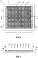
- Figure 3 shows a thermal image of a thermally emissive apparatus 2 corresponding with the embodiment of figure 1 . Areas of the first layer 8 interposed between regions 10 of second material are clearly seen to have an elevated temperature due to Joulean heating within the apparatus 2.
- the thermal image of figure 3 shows a view of the plurality of regions 10 of the second material on the outward facing surface of the first layer 8 and hence the differences in emissivity of the first layer and the regions of second material also has an effect on the emitted thermal infrared radiation.
- the plurality of regions 10 of second material are clearly discernable in the figure as areas of lower temperature than the aforementioned areas of the first layer 8 interposed there-between.
- the size of the regions 10 of second material is preferably selected to be less than individually resolvable through a thermal imaging apparatus.
- Each region of second material within the spatial arrangement is preferably arranged within a 5mm unit cell; unit cells being disposed at a pitch in the range 2 - 5mm.
- the regions 10 of second material are substantially rectilinear in shape.
- the regions are hexagonal or circular.
- thermo-electric heating element 6 is provided with electrodes 12a, 12b running the entire width of opposing sides thereof. This allows the electric field to be applied evenly across the entire width of the heating element to give an even heat distribution. However, this configuration requires the distance between the opposing sides of the heating element to remain constant along the entire width of the heating element, otherwise a heat gradient would occur. Accordingly, only rectangular or square shaped elements can be powered using the embodiment shown in figure 1 .
- FIG 4a which illustrates an example of a conventional circular electro-thermal heating element 16
- current distribution within the element will be highest at 18a and 18b which presents the shortest path between electrodes, and hence lowest resistance, between opposing electrodes 20a, 20b.
- This gives rise to a temperature gradient across element 16 at right angles to direction of predominant current flow, with the top and bottom of the circle as shown in the figure reaching a higher temperature then the centre.
- Said spatial heating variations give rise to corresponding spatial variations in the intensity of infrared radiation emitted by the heating element across the surface thereof.
- Figure 4b illustrates an embodiment of the present thermally emissive apparatus which provides substantially constant heating across a circular electro-thermal heating element.
- the spatial arrangement of the plurality of regions 10 of second material is varied over the first layer 8 of substantially electrically resistive material so as to provide a tailored current distribution within said layer 8 over the entire circle area.
- An even heat distribution can thus be achieved across the surface of the circle, which in turn ensures that the intensity of thermal infrared radiation 14 emitted by the heating element is substantially constant across the surface of the circle.
- the density of regions 10 of second material is varied spatially across the surface of the first layer 8. In this manner the percentage area coverage of said second material varies spatially across the surface of the first layer 8.
- the spatial density of regions 10 of second material is arranged to be high along the longest path between electrodes 26a, 26b in the circular heating element 22 (centre horizontal line in figure 4b ) referred to hence forth as the chord line 28.
- These regions 10 of second material and the electrical contacts with the first layer 8 of first material cooperate to reduce the effective sheet resistivity of the first layer along the chord line 28 of the circle to below that of the first material.
- the resistance of said first layer 8 is reduced in this direction and the current density is correspondingly increased. Consequently, the electro-thermal heating in this direction is increased, giving rise to infrared radiation having a higher intensity than in the prior art apparatus of figure 4a .
- the density of regions 10 of second material reduces in directions substantially perpendicular to the chord line.
- the percentage area coverage of said second material reduces in said directions.
- the density tapers (reducing) with distance from the abovementioned diameter of the circle.
- the spatial arrangement of the plurality of regions of second material relates to the size of said regions (the dimensions and hence the area thereof), the shape of the regions, and the magnitude of the spaces between said discrete regions.
- This technique of varying the density of regions 10 of second material spatially across the surface of the first layer 8 is not limited to circles, but is applicable to other complex, non-rectangular heating elements.
- the technique of varying the spatial arrangement of the plurality of regions 10 of second material over the first layer 8 of substantially electrically resistive material can be used to deliberately induce temperature variations and gradients spatially across an electro-thermal heating element.
- the spatial arrangement of the regions 10 of second material can be varied across the first layer 8 of substantially electrically resistive material to deliberately vary the current distribution within said layer 8 over an area of an electro-thermal heating element.
- the spatial arrangement can be designed so as to increase current density in specific areas of the heating element so that said areas will be achieve higher temperatures than other areas. Variations in heat distribution can thus be achieved across the surface of the heating element, which in turn means that spatial variations in the intensity of thermal infrared radiation emitted by the heating element can be achieved.
- heated profiles can be created within the area of a single electro-thermal heating element.
- a further embodiment of the invention relates to a thermally emissive apparatus for use as a thermal infrared target to simulate a thermal signature of an object.
- a thermal infrared target comprises a thermally emissive apparatus having a plurality of thermo-electric heating elements.
- the thermally emissive apparatus comprises a first layer 30 of a first substantially resistive material as shown in figure 5 .
- the first layer 30 comprises a plurality of areas of said first substantially resistive material, each area corresponding with a different heating element within the apparatus.
- the thermal target depicts a human figure carrying an item diagonally across the upper body.
- areas of the figure's body are simulated by the following respective areas of first material; area 32 corresponds with the figure's head, areas 36 and 40 correspond with the figure's hands and areas 42 - 52 correspond with the figure's legs. Areas 34 and 38 correspond with the carried item.
- the first layer 30 comprises a single layer of a substantially homogeneous first material.
- the first material comprises a carbon based thermoplastic ink (for example, Nicomatic NCC-500C) screen printed onto a substrate (not shown in the figure).
- the substrate comprises a polymer film or paper.
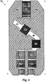
- the thermally emissive apparatus also comprises a second layer 60 of a second substantially conductive material as shown in figure 6 .
- the second layer 60 comprises a plurality of areas of said second substantially conductive material, each area corresponding with a different heating element within the apparatus.
- parts of the figure's body correspond the following respective areas of second material; area 62 corresponds with the figure's head, areas 66 and 70 correspond with the figure's hands and areas 72 - 82 correspond with the figure's legs.
- the second material is omitted from areas 64 and 68.
- the second layer 60 comprises a single layer of a substantially homogeneous second material.
- the second material comprises a silver based ink (for example, Acheson Electrodag PF410) screen printed onto the first layer 30 and the substrate in such a way as to be in electrical contact with the first layer 30.
- a silver based ink for example, Acheson Electrodag PF410
- Electrodes 84a, 84b are also provided in electrical contact with opposing edges of the plurality of heating elements using a substantially conductive ink (for example, Acheson Electrodag PF410).
- a substantially conductive ink for example, Acheson Electrodag PF410.
- Heating elements within the thermal target are arranged to emit thermal infrared radiation having different intensities in order to accurately simulate thermal signature cues corresponding with different parts of the figure's body.
- portions of the target corresponding with the figure's head and hands are arranged in use to be hotter than other parts and hence shall emit thermal infrared radiation having a higher intensity than said other parts.
- Each of the areas 62, 66, 70 - 82 within the second layer comprise a plurality of regions 10 of second material arranged to control the effective sheet resistivity (and hence resistance) of a corresponding area of first material in the first layer 8.
- the spatial arrangement of the plurality of regions 10 of second material is selected within each of said areas 62, 66, 70 - 82 to provide a predetermined current density and hence to provide emission of thermal infrared radiation having a predetermined intensity.
- the spatial arrangement of regions of second material 10 differs between some of the heating elements such that the heating elements emit thermal infrared radiation having different intensities.
- heating elements corresponding with hotter parts of the figure's body have a spatial arrangement having a high density of regions of second material 10.
- the percentage area coverage of said second is thus arranged to be high within said heating elements. This gives rise to a lower average effective sheet resistivity within said heating elements leading to a higher current density and hence a higher average temperature as can be seen in the thermal image in figure 7 .
- cooler parts of the figure's body i.e. the legs
- the percentage area coverage of said second is thus arranged to be lower within said heating elements. This gives rise to a higher average effective sheet resistivity within said heating elements leading to a lower current density and hence a lower average temperature as can be seen in the thermal image in figure 7 .
- first and second materials have been described in terms of thermoplastic inks with the apparatus being fabricated by screen printing, however said first and second materials may comprise any material capable of being applied to the apparatus by a suitable deposition method.
- the apparatus may be fabricated by inkjet printing, flexographic printing, gravure printing, pad printing or any other suitable method.
Landscapes
- Engineering & Computer Science (AREA)
- Physics & Mathematics (AREA)
- Electromagnetism (AREA)
- Radar, Positioning & Navigation (AREA)
- Remote Sensing (AREA)
- General Engineering & Computer Science (AREA)
- Resistance Heating (AREA)
- Surface Heating Bodies (AREA)
Claims (13)
- Thermoemittierende Vorrichtung (2; 22) mit mindestens einem elektrothermischen Heizelement (6), wobei das mindestens eine Heizelement eine erste Schicht (8; 30) eines ersten Werkstoffs mit einem ersten Schichtwiderstand und eine zweite Schicht (60) umfasst, die eine Vielzahl diskreter Bereiche (10) eines zweiten Werkstoffs in elektrischem Kontakt mit dem ersten Werkstoff umfasst, wobei der zweite Werkstoff einen zweiten Schichtwiderstand hat, der im Wesentlichen kleiner als der des ersten Werkstoffs ist, wobei das Heizelement (6) Elektroden (12a, 12b; 26a, 26b; 84a, 84b) zum Anwenden eines elektrischen Felds über die erste Schicht des mindestens einen Heizelements umfasst, um Stromwärme desselben zu erzeugen, wobei die räumliche Anordnung der Bereiche des zweiten Werkstoffs in dem mindestens einen Heizelement so ungleichförmig ist, dass der wirksame Schichtwiderstand der ersten Schicht räumlich in Bezug auf die räumliche Anordnung der Bereiche des zweiten Werkstoffs variiert.
- Thermoemittierende Vorrichtung nach Anspruch 1, wobei die Vielzahl der Bereiche des zweiten Werkstoffs eine räumliche Anordnung hat, die mit der ersten Schicht zusammenwirkt, um einen vorbestimmten wirksamen Schichtwiderstand auf die erste Schicht in der Nähe der Vielzahl der Bereiche zu übertragen.
- Thermoemittierende Vorrichtung nach Anspruch 2, wobei die räumliche Änderung des wirksamen Schichtwiderstands der ersten Schicht angeordnet wird, um beim Einsatz eine im Wesentlichen gleichförmige Stromdichte innerhalb der ersten Schicht bereitzustellen.
- Thermoemittierende Vorrichtung nach Anspruch 2 oder 3, wobei die räumliche Änderung des wirksamen Schichtwiderstands der ersten Schicht angeordnet wird, um beim Einsatz eine im Wesentlichen gleichförmige Stromwärme des Heizelements bereitzustellen.
- Thermoemittierende Vorrichtung nach einem der vorhergehenden Ansprüche mit einer Vielzahl elektrothermischer Heizelemente, die räumlich auf einer Oberfläche derselben angeordnet werden, wobei die Vielzahl von Heizelementen eine gemeinsame erste Schicht des ersten Werkstoffs hat.
- Thermoemittierende Vorrichtung nach Anspruch 5, wobei die Vielzahl von Heizelementen mindestens eine gemeinsame elektrische Verbindung hat.
- Thermoemittierende Vorrichtung nach Anspruch 5 oder 6, wenn direkt oder indirekt von einem Anspruch 2 bis 5 abhängig, wobei die räumliche Anordnung der Bereiche des zweiten Werkstoffs innerhalb der Vielzahl von Heizelementen dieselbe ist.
- Thermoemittierende Vorrichtung nach Anspruch 5 oder 6, wenn direkt oder indirekt von einem Anspruch 2 bis 5 abhängig, wobei die räumliche Anordnung der Bereiche des zweiten Werkstoffs innerhalb eines ersten Heizelements unterschiedlich zu der innerhalb eines zweiten Heizelements ist.
- Thermoemittierende Vorrichtung nach einem der vorhergehenden Ansprüche, die Infrarotstrahlung mit einer Wellenlänge im Bereich 1 µm bis 100 µm ausstrahlt.
- Thermoemittierende Vorrichtung nach einem der vorhergehenden Ansprüche, die als ein thermisches Target angeordnet wird, um die thermische Signatur eines Ziels zu simulieren.
- Thermoemittierende Vorrichtung nach einem der Ansprüche 1 bis 9, die als eine elektrothermische Vereisungsschutzvorrichtung angeordnet wird, um Vereisungsschutz einer aerodynamischen Oberfläche bereitzustellen.
- Einsatz einer thermoemittierenden Vorrichtung nach einem der Ansprüche 1 bis 9 als ein thermisches Target, um die thermische Signatur eines Ziels zu simulieren.
- Einsatz einer thermoemittierenden Vorrichtung nach einem der Ansprüche 1 bis 9 als eine elektrothermische Vereisungsschutzvorrichtung, um Vereisungsschutz einer aerodynamischen Oberfläche bereitzustellen.
Applications Claiming Priority (2)
| Application Number | Priority Date | Filing Date | Title |
|---|---|---|---|
| GB0816376A GB2463284B (en) | 2008-09-08 | 2008-09-08 | Thermal emissive apparatus |
| PCT/GB2009/002072 WO2010026364A1 (en) | 2008-09-08 | 2009-08-26 | Thermally emissive apparatus |
Publications (2)
| Publication Number | Publication Date |
|---|---|
| EP2331901A1 EP2331901A1 (de) | 2011-06-15 |
| EP2331901B1 true EP2331901B1 (de) | 2017-07-05 |
Family
ID=39888975
Family Applications (1)
| Application Number | Title | Priority Date | Filing Date |
|---|---|---|---|
| EP09785007.7A Active EP2331901B1 (de) | 2008-09-08 | 2009-08-26 | Wärmeemittierende vorrichtung |
Country Status (5)
| Country | Link |
|---|---|
| US (1) | US10060711B2 (de) |
| EP (1) | EP2331901B1 (de) |
| AU (1) | AU2009289124B2 (de) |
| GB (1) | GB2463284B (de) |
| WO (1) | WO2010026364A1 (de) |
Families Citing this family (14)
| Publication number | Priority date | Publication date | Assignee | Title |
|---|---|---|---|---|
| DE102010060807A1 (de) * | 2010-11-25 | 2012-05-31 | Dr. Ing. H.C. F. Porsche Aktiengesellschaft | Testvorrichtung |
| US8935286B1 (en) * | 2011-06-16 | 2015-01-13 | The Boeing Company | Interactive system for managing parts and information for parts |
| DE102012015056A1 (de) * | 2012-07-28 | 2014-02-13 | Bsautomatisierung Gmbh | Robotersteuerungsvorrichtung |
| KR101438465B1 (ko) * | 2012-10-18 | 2014-09-12 | 주식회사 티앤비나노일렉 | 휴대용 보조 난방 장치 |
| LU92228B1 (de) * | 2013-06-20 | 2014-12-22 | Iee Sarl | Heizfähiges Innenraumverkleidungselement |
| CN104215132A (zh) * | 2014-08-21 | 2014-12-17 | 北京盘庚瑞桓微电子技术有限公司 | 新型热辐射靶标 |
| GB2535499A (en) * | 2015-02-18 | 2016-08-24 | Xefro Ip Ltd | Heaters |
| CN105676770A (zh) * | 2016-01-19 | 2016-06-15 | 西北工业大学 | 一种用于气动加热模拟试验系统的多通道数据采集方法 |
| US10465976B2 (en) * | 2016-05-19 | 2019-11-05 | Bsh Home Appliances Corporation | Cooking within a refrigeration cavity |
| CN108318141B (zh) * | 2018-04-20 | 2024-04-19 | 深圳市道通科技股份有限公司 | 发热件的温度控制方法、夜视系统标定设备及系统 |
| US11084593B2 (en) | 2018-10-11 | 2021-08-10 | Goodrich Corporation | Additive manufactured heater elements for propeller ice protection |
| CN111521068B (zh) * | 2020-03-18 | 2022-04-12 | 哈尔滨新光光电科技股份有限公司 | 一种红外点源引偏装置及控制方法 |
| US11604049B2 (en) * | 2020-06-25 | 2023-03-14 | Dobbelgänger Oy | Multi-spectral artificial target device and a method for producing the same as well as a method of generating a thermal and radar signature of an object with an artificial target device |
| CN112385906A (zh) * | 2020-07-02 | 2021-02-23 | 湖北中烟工业有限责任公司 | 加热组件和加热不燃烧装置 |
Citations (6)
| Publication number | Priority date | Publication date | Assignee | Title |
|---|---|---|---|---|
| US4240212A (en) * | 1979-06-21 | 1980-12-23 | The United States Of America As Represented By The Secretary Of The Navy | Thermal signature targets |
| US4659089A (en) * | 1981-09-18 | 1987-04-21 | Tvi Energy Corporation | Multi-spectral target |
| US4792142A (en) * | 1987-11-13 | 1988-12-20 | Davies Robert M | Thermal target device |
| US5065032A (en) * | 1990-09-10 | 1991-11-12 | Custom Training Aids | Thermal integrated target |
| WO1999010914A1 (en) * | 1997-08-29 | 1999-03-04 | Fogarty Charles M | Infrared emissive module |
| US6338292B1 (en) * | 1999-09-30 | 2002-01-15 | Robert Fisher Reynolds | Thermal and visual camouflage system |
Family Cites Families (20)
| Publication number | Priority date | Publication date | Assignee | Title |
|---|---|---|---|---|
| US3735137A (en) * | 1972-05-02 | 1973-05-22 | Us Army | Large, two dimension, screen for converting an optical image projected on one side to an identical infrared image display on the other side |
| US4058734A (en) * | 1976-07-19 | 1977-11-15 | The United States Of America As Represented By The Secretary Of The Air Force | Passive infrared resolution target |
| US4546983A (en) * | 1981-09-18 | 1985-10-15 | Tvi Energy Corporation | Multi-spectral target |
| US4706251A (en) * | 1985-03-18 | 1987-11-10 | Arthur D. Little, Inc. | Voltage tunable coherent light source |
| GB8802140D0 (en) * | 1988-02-01 | 1988-03-02 | Imvec Ltd | Electrically-heated thermally-emissive weaponry target training air/arc designator structure |
| US4946171A (en) * | 1989-01-03 | 1990-08-07 | Eastman Kodak Company | Live fire target modular support structure |
| US5296270A (en) * | 1991-09-05 | 1994-03-22 | Custom Training Aids, Inc. | Process for making a thermally radiant surface |
| US7233978B2 (en) * | 1998-07-08 | 2007-06-19 | Econnectix, Llc | Method and apparatus for managing location information in a network separate from the data to which the location information pertains |
| US6180929B1 (en) * | 1998-08-06 | 2001-01-30 | Clearpath, Inc. | Heating pad apparatus adapted for outdoor use |
| DE29822007U1 (de) * | 1998-12-10 | 1999-04-08 | Bischoff, Robert, 06108 Halle | Elektrodenanordnung für ein elektrisches Bauelement und als Träger für Sensoren |
| US6963850B1 (en) * | 1999-04-09 | 2005-11-08 | Amazon.Com, Inc. | Computer services for assisting users in locating and evaluating items in an electronic catalog based on actions performed by members of specific user communities |
| US6956852B1 (en) * | 1999-06-25 | 2005-10-18 | Cisco Technology Inc. | Multi-function high-speed network interface |
| US7092505B2 (en) * | 1999-12-23 | 2006-08-15 | Tekelec | Methods and systems for universal, automatic service selection in a telecommunications signaling network |
| GB0027510D0 (en) * | 2000-11-10 | 2000-12-27 | Secr Defence | Surface with varying electrical or magnetic properties |
| DE602006006547D1 (de) * | 2005-02-09 | 2009-06-10 | Qinetiq Ltd | Elektrothermische heizvorrichtung zum schutz von aerodynamischen oberflächen vor eis und ihre herstellungsverfahren |
| US20080296842A1 (en) * | 2005-10-06 | 2008-12-04 | Novak Harvey M | Multi-spectral targets for gunnery training |
| EP2064720A4 (de) * | 2006-09-11 | 2012-11-28 | Bruce Hodge | Target mit ansteigender wärme |
| US8321568B2 (en) * | 2008-03-31 | 2012-11-27 | Amazon Technologies, Inc. | Content management |
| EP2175613A1 (de) * | 2008-10-08 | 2010-04-14 | Research In Motion Limited | Vorrichtung und System für mobile drahtlose Kommunikation zur Bereitstellung der Verwaltung von Trägeranwendungen und zugehörige Verfahren |
| US20100192225A1 (en) * | 2009-01-28 | 2010-07-29 | Juniper Networks, Inc. | Efficient application identification with network devices |
-
2008
- 2008-09-08 GB GB0816376A patent/GB2463284B/en active Active
-
2009
- 2009-08-26 US US13/060,213 patent/US10060711B2/en active Active
- 2009-08-26 AU AU2009289124A patent/AU2009289124B2/en active Active
- 2009-08-26 WO PCT/GB2009/002072 patent/WO2010026364A1/en not_active Ceased
- 2009-08-26 EP EP09785007.7A patent/EP2331901B1/de active Active
Patent Citations (6)
| Publication number | Priority date | Publication date | Assignee | Title |
|---|---|---|---|---|
| US4240212A (en) * | 1979-06-21 | 1980-12-23 | The United States Of America As Represented By The Secretary Of The Navy | Thermal signature targets |
| US4659089A (en) * | 1981-09-18 | 1987-04-21 | Tvi Energy Corporation | Multi-spectral target |
| US4792142A (en) * | 1987-11-13 | 1988-12-20 | Davies Robert M | Thermal target device |
| US5065032A (en) * | 1990-09-10 | 1991-11-12 | Custom Training Aids | Thermal integrated target |
| WO1999010914A1 (en) * | 1997-08-29 | 1999-03-04 | Fogarty Charles M | Infrared emissive module |
| US6338292B1 (en) * | 1999-09-30 | 2002-01-15 | Robert Fisher Reynolds | Thermal and visual camouflage system |
Also Published As
| Publication number | Publication date |
|---|---|
| EP2331901A1 (de) | 2011-06-15 |
| AU2009289124A1 (en) | 2010-03-11 |
| US20110147369A1 (en) | 2011-06-23 |
| US10060711B2 (en) | 2018-08-28 |
| WO2010026364A1 (en) | 2010-03-11 |
| GB2463284A (en) | 2010-03-10 |
| GB0816376D0 (en) | 2008-10-15 |
| AU2009289124B2 (en) | 2014-05-08 |
| GB2463284B (en) | 2011-11-23 |
Similar Documents
| Publication | Publication Date | Title |
|---|---|---|
| EP2331901B1 (de) | Wärmeemittierende vorrichtung | |
| KR102007588B1 (ko) | 흑체 스펙트럼을 생성하기 위한 장치 및 방법 및 흑체 방사 스펙트럼을 발생시키기 위한 필름 | |
| US20100077598A1 (en) | Cable wrap system | |
| SE1150517A1 (sv) | Anordning för signaturanpassning | |
| WO2016169481A1 (zh) | 一种电热膜器件及其制备方法以及电热装置 | |
| RU2013154419A (ru) | Устройство и способ для адаптации сигнатуры и объект с таким устройством | |
| JP2019079036A5 (de) | ||
| US20110272394A1 (en) | Heating element and a manufacturing method thereof | |
| Anas et al. | Joule heating of carbon pixels for on-demand thermal patterning | |
| KR20130107256A (ko) | 발열체 및 이의 제조방법 | |
| WO2002043445A2 (en) | Thermal image identification system | |
| KR20200087077A (ko) | 광학적으로 투명한 전자기 차폐 어셈블리 | |
| US12018920B2 (en) | Multi-spectral artificial target device and a method for producing the same as well as a method of generating a thermal and radar signature of an object with an artificial target device | |
| Long et al. | Geometrically engineered heating arrays enabled by electric-field-driven 3D printing for on-demand thermal patterning | |
| JP2007149598A (ja) | シート状温度制御装置 | |
| EP4259997B1 (de) | Mehrschichtige, ultradünne und flexible heizungseinheitszellen für infrarot-stealth | |
| US20230056085A1 (en) | Multi-layered multi-spectral target for rifles | |
| Cen et al. | Design of flexible printed heater to improve uniform heating | |
| RU106821U1 (ru) | Электронагреватель | |
| KR20100092560A (ko) | 전기 핫 플레이트 | |
| KR20100083535A (ko) | 전기 토스터기 | |
| EP4041677B1 (de) | Verfahren und vorrichtung zur erzeugung einer thermischen signatur | |
| Escobedo Araque et al. | Comparative Study of Inkjet-Printed Silver Conductive Traces With Thermal and Electrical Sintering | |
| CN105659878B (zh) | 阵列式中低温热目标模拟器 | |
| CN119310758A (zh) | 空间光调制单元及空间光调制器件 |
Legal Events
| Date | Code | Title | Description |
|---|---|---|---|
| PUAI | Public reference made under article 153(3) epc to a published international application that has entered the european phase |
Free format text: ORIGINAL CODE: 0009012 |
|
| 17P | Request for examination filed |
Effective date: 20110324 |
|
| AK | Designated contracting states |
Kind code of ref document: A1 Designated state(s): AT BE BG CH CY CZ DE DK EE ES FI FR GB GR HR HU IE IS IT LI LT LU LV MC MK MT NL NO PL PT RO SE SI SK SM TR |
|
| AX | Request for extension of the european patent |
Extension state: AL BA RS |
|
| RIN1 | Information on inventor provided before grant (corrected) |
Inventor name: TREEN, ANDREW, SHAUN Inventor name: ADAMS, PAUL, BARRIE Inventor name: SPOONER, CHRISTOPHER, DOUGLAS, JAMES Inventor name: FIXTER, GREG, PETER, WADE |
|
| DAX | Request for extension of the european patent (deleted) | ||
| 17Q | First examination report despatched |
Effective date: 20150226 |
|
| RIC1 | Information provided on ipc code assigned before grant |
Ipc: F41J 2/02 20060101AFI20161108BHEP Ipc: H05B 3/26 20060101ALI20161108BHEP |
|
| GRAP | Despatch of communication of intention to grant a patent |
Free format text: ORIGINAL CODE: EPIDOSNIGR1 |
|
| INTG | Intention to grant announced |
Effective date: 20170126 |
|
| GRAS | Grant fee paid |
Free format text: ORIGINAL CODE: EPIDOSNIGR3 |
|
| GRAA | (expected) grant |
Free format text: ORIGINAL CODE: 0009210 |
|
| AK | Designated contracting states |
Kind code of ref document: B1 Designated state(s): AT BE BG CH CY CZ DE DK EE ES FI FR GB GR HR HU IE IS IT LI LT LU LV MC MK MT NL NO PL PT RO SE SI SK SM TR |
|
| REG | Reference to a national code |
Ref country code: GB Ref legal event code: FG4D |
|
| REG | Reference to a national code |
Ref country code: CH Ref legal event code: EP |
|
| REG | Reference to a national code |
Ref country code: AT Ref legal event code: REF Ref document number: 906887 Country of ref document: AT Kind code of ref document: T Effective date: 20170715 |
|
| REG | Reference to a national code |
Ref country code: IE Ref legal event code: FG4D |
|
| REG | Reference to a national code |
Ref country code: DE Ref legal event code: R096 Ref document number: 602009046996 Country of ref document: DE |
|
| REG | Reference to a national code |
Ref country code: FR Ref legal event code: PLFP Year of fee payment: 9 |
|
| REG | Reference to a national code |
Ref country code: NL Ref legal event code: MP Effective date: 20170705 |
|
| REG | Reference to a national code |
Ref country code: AT Ref legal event code: MK05 Ref document number: 906887 Country of ref document: AT Kind code of ref document: T Effective date: 20170705 |
|
| REG | Reference to a national code |
Ref country code: LT Ref legal event code: MG4D |
|
| PG25 | Lapsed in a contracting state [announced via postgrant information from national office to epo] |
Ref country code: LT Free format text: LAPSE BECAUSE OF FAILURE TO SUBMIT A TRANSLATION OF THE DESCRIPTION OR TO PAY THE FEE WITHIN THE PRESCRIBED TIME-LIMIT Effective date: 20170705 Ref country code: SE Free format text: LAPSE BECAUSE OF FAILURE TO SUBMIT A TRANSLATION OF THE DESCRIPTION OR TO PAY THE FEE WITHIN THE PRESCRIBED TIME-LIMIT Effective date: 20170705 Ref country code: NO Free format text: LAPSE BECAUSE OF FAILURE TO SUBMIT A TRANSLATION OF THE DESCRIPTION OR TO PAY THE FEE WITHIN THE PRESCRIBED TIME-LIMIT Effective date: 20171005 Ref country code: AT Free format text: LAPSE BECAUSE OF FAILURE TO SUBMIT A TRANSLATION OF THE DESCRIPTION OR TO PAY THE FEE WITHIN THE PRESCRIBED TIME-LIMIT Effective date: 20170705 Ref country code: FI Free format text: LAPSE BECAUSE OF FAILURE TO SUBMIT A TRANSLATION OF THE DESCRIPTION OR TO PAY THE FEE WITHIN THE PRESCRIBED TIME-LIMIT Effective date: 20170705 Ref country code: HR Free format text: LAPSE BECAUSE OF FAILURE TO SUBMIT A TRANSLATION OF THE DESCRIPTION OR TO PAY THE FEE WITHIN THE PRESCRIBED TIME-LIMIT Effective date: 20170705 Ref country code: NL Free format text: LAPSE BECAUSE OF FAILURE TO SUBMIT A TRANSLATION OF THE DESCRIPTION OR TO PAY THE FEE WITHIN THE PRESCRIBED TIME-LIMIT Effective date: 20170705 |
|
| PG25 | Lapsed in a contracting state [announced via postgrant information from national office to epo] |
Ref country code: GR Free format text: LAPSE BECAUSE OF FAILURE TO SUBMIT A TRANSLATION OF THE DESCRIPTION OR TO PAY THE FEE WITHIN THE PRESCRIBED TIME-LIMIT Effective date: 20171006 Ref country code: BG Free format text: LAPSE BECAUSE OF FAILURE TO SUBMIT A TRANSLATION OF THE DESCRIPTION OR TO PAY THE FEE WITHIN THE PRESCRIBED TIME-LIMIT Effective date: 20171005 Ref country code: LV Free format text: LAPSE BECAUSE OF FAILURE TO SUBMIT A TRANSLATION OF THE DESCRIPTION OR TO PAY THE FEE WITHIN THE PRESCRIBED TIME-LIMIT Effective date: 20170705 Ref country code: PL Free format text: LAPSE BECAUSE OF FAILURE TO SUBMIT A TRANSLATION OF THE DESCRIPTION OR TO PAY THE FEE WITHIN THE PRESCRIBED TIME-LIMIT Effective date: 20170705 Ref country code: ES Free format text: LAPSE BECAUSE OF FAILURE TO SUBMIT A TRANSLATION OF THE DESCRIPTION OR TO PAY THE FEE WITHIN THE PRESCRIBED TIME-LIMIT Effective date: 20170705 Ref country code: IS Free format text: LAPSE BECAUSE OF FAILURE TO SUBMIT A TRANSLATION OF THE DESCRIPTION OR TO PAY THE FEE WITHIN THE PRESCRIBED TIME-LIMIT Effective date: 20171105 |
|
| REG | Reference to a national code |
Ref country code: CH Ref legal event code: PL |
|
| REG | Reference to a national code |
Ref country code: DE Ref legal event code: R097 Ref document number: 602009046996 Country of ref document: DE |
|
| PG25 | Lapsed in a contracting state [announced via postgrant information from national office to epo] |
Ref country code: MC Free format text: LAPSE BECAUSE OF FAILURE TO SUBMIT A TRANSLATION OF THE DESCRIPTION OR TO PAY THE FEE WITHIN THE PRESCRIBED TIME-LIMIT Effective date: 20170705 Ref country code: CH Free format text: LAPSE BECAUSE OF NON-PAYMENT OF DUE FEES Effective date: 20170831 Ref country code: DK Free format text: LAPSE BECAUSE OF FAILURE TO SUBMIT A TRANSLATION OF THE DESCRIPTION OR TO PAY THE FEE WITHIN THE PRESCRIBED TIME-LIMIT Effective date: 20170705 Ref country code: RO Free format text: LAPSE BECAUSE OF FAILURE TO SUBMIT A TRANSLATION OF THE DESCRIPTION OR TO PAY THE FEE WITHIN THE PRESCRIBED TIME-LIMIT Effective date: 20170705 Ref country code: LI Free format text: LAPSE BECAUSE OF NON-PAYMENT OF DUE FEES Effective date: 20170831 Ref country code: CZ Free format text: LAPSE BECAUSE OF FAILURE TO SUBMIT A TRANSLATION OF THE DESCRIPTION OR TO PAY THE FEE WITHIN THE PRESCRIBED TIME-LIMIT Effective date: 20170705 |
|
| PLBE | No opposition filed within time limit |
Free format text: ORIGINAL CODE: 0009261 |
|
| STAA | Information on the status of an ep patent application or granted ep patent |
Free format text: STATUS: NO OPPOSITION FILED WITHIN TIME LIMIT |
|
| REG | Reference to a national code |
Ref country code: IE Ref legal event code: MM4A |
|
| PG25 | Lapsed in a contracting state [announced via postgrant information from national office to epo] |
Ref country code: IT Free format text: LAPSE BECAUSE OF FAILURE TO SUBMIT A TRANSLATION OF THE DESCRIPTION OR TO PAY THE FEE WITHIN THE PRESCRIBED TIME-LIMIT Effective date: 20170705 Ref country code: SM Free format text: LAPSE BECAUSE OF FAILURE TO SUBMIT A TRANSLATION OF THE DESCRIPTION OR TO PAY THE FEE WITHIN THE PRESCRIBED TIME-LIMIT Effective date: 20170705 Ref country code: SK Free format text: LAPSE BECAUSE OF FAILURE TO SUBMIT A TRANSLATION OF THE DESCRIPTION OR TO PAY THE FEE WITHIN THE PRESCRIBED TIME-LIMIT Effective date: 20170705 Ref country code: EE Free format text: LAPSE BECAUSE OF FAILURE TO SUBMIT A TRANSLATION OF THE DESCRIPTION OR TO PAY THE FEE WITHIN THE PRESCRIBED TIME-LIMIT Effective date: 20170705 |
|
| REG | Reference to a national code |
Ref country code: BE Ref legal event code: MM Effective date: 20170831 |
|
| 26N | No opposition filed |
Effective date: 20180406 |
|
| PG25 | Lapsed in a contracting state [announced via postgrant information from national office to epo] |
Ref country code: LU Free format text: LAPSE BECAUSE OF NON-PAYMENT OF DUE FEES Effective date: 20170826 |
|
| PG25 | Lapsed in a contracting state [announced via postgrant information from national office to epo] |
Ref country code: IE Free format text: LAPSE BECAUSE OF NON-PAYMENT OF DUE FEES Effective date: 20170826 |
|
| REG | Reference to a national code |
Ref country code: FR Ref legal event code: PLFP Year of fee payment: 10 |
|
| PG25 | Lapsed in a contracting state [announced via postgrant information from national office to epo] |
Ref country code: BE Free format text: LAPSE BECAUSE OF NON-PAYMENT OF DUE FEES Effective date: 20170831 Ref country code: SI Free format text: LAPSE BECAUSE OF FAILURE TO SUBMIT A TRANSLATION OF THE DESCRIPTION OR TO PAY THE FEE WITHIN THE PRESCRIBED TIME-LIMIT Effective date: 20170705 |
|
| PG25 | Lapsed in a contracting state [announced via postgrant information from national office to epo] |
Ref country code: MT Free format text: LAPSE BECAUSE OF NON-PAYMENT OF DUE FEES Effective date: 20170826 |
|
| PG25 | Lapsed in a contracting state [announced via postgrant information from national office to epo] |
Ref country code: HU Free format text: LAPSE BECAUSE OF FAILURE TO SUBMIT A TRANSLATION OF THE DESCRIPTION OR TO PAY THE FEE WITHIN THE PRESCRIBED TIME-LIMIT; INVALID AB INITIO Effective date: 20090826 |
|
| PG25 | Lapsed in a contracting state [announced via postgrant information from national office to epo] |
Ref country code: CY Free format text: LAPSE BECAUSE OF NON-PAYMENT OF DUE FEES Effective date: 20170705 |
|
| PG25 | Lapsed in a contracting state [announced via postgrant information from national office to epo] |
Ref country code: MK Free format text: LAPSE BECAUSE OF FAILURE TO SUBMIT A TRANSLATION OF THE DESCRIPTION OR TO PAY THE FEE WITHIN THE PRESCRIBED TIME-LIMIT Effective date: 20170705 |
|
| PG25 | Lapsed in a contracting state [announced via postgrant information from national office to epo] |
Ref country code: TR Free format text: LAPSE BECAUSE OF FAILURE TO SUBMIT A TRANSLATION OF THE DESCRIPTION OR TO PAY THE FEE WITHIN THE PRESCRIBED TIME-LIMIT Effective date: 20170705 |
|
| PG25 | Lapsed in a contracting state [announced via postgrant information from national office to epo] |
Ref country code: PT Free format text: LAPSE BECAUSE OF FAILURE TO SUBMIT A TRANSLATION OF THE DESCRIPTION OR TO PAY THE FEE WITHIN THE PRESCRIBED TIME-LIMIT Effective date: 20170705 |
|
| P01 | Opt-out of the competence of the unified patent court (upc) registered |
Effective date: 20230401 |
|
| PGFP | Annual fee paid to national office [announced via postgrant information from national office to epo] |
Ref country code: DE Payment date: 20250827 Year of fee payment: 17 |
|
| PGFP | Annual fee paid to national office [announced via postgrant information from national office to epo] |
Ref country code: GB Payment date: 20250827 Year of fee payment: 17 |
|
| PGFP | Annual fee paid to national office [announced via postgrant information from national office to epo] |
Ref country code: FR Payment date: 20250825 Year of fee payment: 17 |