EP2331225B1 - Devices and method for continuous distillative separation of a mixture containing one or more alkanolamine(s) - Google Patents
Devices and method for continuous distillative separation of a mixture containing one or more alkanolamine(s) Download PDFInfo
- Publication number
- EP2331225B1 EP2331225B1 EP09783090.5A EP09783090A EP2331225B1 EP 2331225 B1 EP2331225 B1 EP 2331225B1 EP 09783090 A EP09783090 A EP 09783090A EP 2331225 B1 EP2331225 B1 EP 2331225B1
- Authority
- EP
- European Patent Office
- Prior art keywords
- column
- dividing wall
- process according
- feed
- section
- Prior art date
- Legal status (The legal status is an assumption and is not a legal conclusion. Google has not performed a legal analysis and makes no representation as to the accuracy of the status listed.)
- Active
Links
- 238000000034 method Methods 0.000 title claims description 47
- 239000000203 mixture Substances 0.000 title claims description 36
- 238000007700 distillative separation Methods 0.000 title claims description 8
- 239000007788 liquid Substances 0.000 claims description 47
- SLINHMUFWFWBMU-UHFFFAOYSA-N Triisopropanolamine Chemical compound CC(O)CN(CC(C)O)CC(C)O SLINHMUFWFWBMU-UHFFFAOYSA-N 0.000 claims description 30
- LVTYICIALWPMFW-UHFFFAOYSA-N diisopropanolamine Chemical compound CC(O)CNCC(C)O LVTYICIALWPMFW-UHFFFAOYSA-N 0.000 claims description 30
- HXKKHQJGJAFBHI-UHFFFAOYSA-N 1-aminopropan-2-ol Chemical compound CC(O)CN HXKKHQJGJAFBHI-UHFFFAOYSA-N 0.000 claims description 29
- 229940043276 diisopropanolamine Drugs 0.000 claims description 29
- 238000004821 distillation Methods 0.000 claims description 25
- QGZKDVFQNNGYKY-UHFFFAOYSA-N Ammonia Chemical compound N QGZKDVFQNNGYKY-UHFFFAOYSA-N 0.000 claims description 16
- XLYOFNOQVPJJNP-UHFFFAOYSA-N water Substances O XLYOFNOQVPJJNP-UHFFFAOYSA-N 0.000 claims description 14
- 238000010438 heat treatment Methods 0.000 claims description 13
- GOOHAUXETOMSMM-UHFFFAOYSA-N Propylene oxide Chemical compound CC1CO1 GOOHAUXETOMSMM-UHFFFAOYSA-N 0.000 claims description 9
- 229910021529 ammonia Inorganic materials 0.000 claims description 8
- 238000012856 packing Methods 0.000 claims description 7
- 230000008878 coupling Effects 0.000 claims description 3
- 238000010168 coupling process Methods 0.000 claims description 3
- 238000005859 coupling reaction Methods 0.000 claims description 3
- 238000009413 insulation Methods 0.000 claims description 3
- 238000005259 measurement Methods 0.000 claims description 3
- 230000003068 static effect Effects 0.000 claims description 3
- 238000009434 installation Methods 0.000 claims description 2
- 230000002051 biphasic effect Effects 0.000 claims 2
- 230000000694 effects Effects 0.000 claims 2
- 238000000926 separation method Methods 0.000 description 13
- 238000005192 partition Methods 0.000 description 11
- 238000006243 chemical reaction Methods 0.000 description 9
- 238000009835 boiling Methods 0.000 description 7
- 239000000047 product Substances 0.000 description 7
- 239000006227 byproduct Substances 0.000 description 6
- 238000013461 design Methods 0.000 description 6
- 241001550224 Apha Species 0.000 description 5
- HZAXFHJVJLSVMW-UHFFFAOYSA-N 2-Aminoethan-1-ol Chemical compound NCCO HZAXFHJVJLSVMW-UHFFFAOYSA-N 0.000 description 4
- GLUUGHFHXGJENI-UHFFFAOYSA-N Piperazine Chemical compound C1CNCCN1 GLUUGHFHXGJENI-UHFFFAOYSA-N 0.000 description 4
- 238000010327 methods by industry Methods 0.000 description 4
- 238000002156 mixing Methods 0.000 description 4
- 230000003014 reinforcing effect Effects 0.000 description 4
- GSEJCLTVZPLZKY-UHFFFAOYSA-N Triethanolamine Chemical compound OCCN(CCO)CCO GSEJCLTVZPLZKY-UHFFFAOYSA-N 0.000 description 3
- 238000001816 cooling Methods 0.000 description 3
- 238000009826 distribution Methods 0.000 description 3
- 238000000746 purification Methods 0.000 description 3
- 238000005070 sampling Methods 0.000 description 3
- RTZKZFJDLAIYFH-UHFFFAOYSA-N Diethyl ether Chemical compound CCOCC RTZKZFJDLAIYFH-UHFFFAOYSA-N 0.000 description 2
- RPNUMPOLZDHAAY-UHFFFAOYSA-N Diethylenetriamine Chemical compound NCCNCCN RPNUMPOLZDHAAY-UHFFFAOYSA-N 0.000 description 2
- PIICEJLVQHRZGT-UHFFFAOYSA-N Ethylenediamine Chemical compound NCCN PIICEJLVQHRZGT-UHFFFAOYSA-N 0.000 description 2
- 241000350481 Pterogyne nitens Species 0.000 description 2
- LHIJANUOQQMGNT-UHFFFAOYSA-N aminoethylethanolamine Chemical compound NCCNCCO LHIJANUOQQMGNT-UHFFFAOYSA-N 0.000 description 2
- 238000003889 chemical engineering Methods 0.000 description 2
- 239000003795 chemical substances by application Substances 0.000 description 2
- 239000013256 coordination polymer Substances 0.000 description 2
- 238000005265 energy consumption Methods 0.000 description 2
- 230000002349 favourable effect Effects 0.000 description 2
- 239000007791 liquid phase Substances 0.000 description 2
- 239000012071 phase Substances 0.000 description 2
- 238000004886 process control Methods 0.000 description 2
- 230000001105 regulatory effect Effects 0.000 description 2
- QAEDZJGFFMLHHQ-UHFFFAOYSA-N trifluoroacetic anhydride Chemical compound FC(F)(F)C(=O)OC(=O)C(F)(F)F QAEDZJGFFMLHHQ-UHFFFAOYSA-N 0.000 description 2
- 238000010626 work up procedure Methods 0.000 description 2
- 102100032373 Coiled-coil domain-containing protein 85B Human genes 0.000 description 1
- 239000005977 Ethylene Substances 0.000 description 1
- IAYPIBMASNFSPL-UHFFFAOYSA-N Ethylene oxide Chemical compound C1CO1 IAYPIBMASNFSPL-UHFFFAOYSA-N 0.000 description 1
- 101000868814 Homo sapiens Coiled-coil domain-containing protein 85B Proteins 0.000 description 1
- 238000003109 Karl Fischer titration Methods 0.000 description 1
- 230000009286 beneficial effect Effects 0.000 description 1
- 230000015572 biosynthetic process Effects 0.000 description 1
- 238000011217 control strategy Methods 0.000 description 1
- 238000000354 decomposition reaction Methods 0.000 description 1
- 238000001212 derivatisation Methods 0.000 description 1
- ZBCBWPMODOFKDW-UHFFFAOYSA-N diethanolamine Chemical compound OCCNCCO ZBCBWPMODOFKDW-UHFFFAOYSA-N 0.000 description 1
- -1 ethylene amines Chemical class 0.000 description 1
- 238000000605 extraction Methods 0.000 description 1
- 239000012530 fluid Substances 0.000 description 1
- 238000004817 gas chromatography Methods 0.000 description 1
- 230000002427 irreversible effect Effects 0.000 description 1
- 238000004519 manufacturing process Methods 0.000 description 1
- 239000002184 metal Substances 0.000 description 1
- 238000002360 preparation method Methods 0.000 description 1
- 239000011541 reaction mixture Substances 0.000 description 1
- 238000004064 recycling Methods 0.000 description 1
- 230000002787 reinforcement Effects 0.000 description 1
- 238000003786 synthesis reaction Methods 0.000 description 1
- 238000012546 transfer Methods 0.000 description 1
Images


Classifications
-
- B—PERFORMING OPERATIONS; TRANSPORTING
- B01—PHYSICAL OR CHEMICAL PROCESSES OR APPARATUS IN GENERAL
- B01D—SEPARATION
- B01D3/00—Distillation or related exchange processes in which liquids are contacted with gaseous media, e.g. stripping
- B01D3/14—Fractional distillation or use of a fractionation or rectification column
- B01D3/32—Other features of fractionating columns ; Constructional details of fractionating columns not provided for in groups B01D3/16 - B01D3/30
-
- B—PERFORMING OPERATIONS; TRANSPORTING
- B01—PHYSICAL OR CHEMICAL PROCESSES OR APPARATUS IN GENERAL
- B01D—SEPARATION
- B01D3/00—Distillation or related exchange processes in which liquids are contacted with gaseous media, e.g. stripping
- B01D3/14—Fractional distillation or use of a fractionation or rectification column
-
- B—PERFORMING OPERATIONS; TRANSPORTING
- B01—PHYSICAL OR CHEMICAL PROCESSES OR APPARATUS IN GENERAL
- B01D—SEPARATION
- B01D3/00—Distillation or related exchange processes in which liquids are contacted with gaseous media, e.g. stripping
- B01D3/42—Regulation; Control
-
- C—CHEMISTRY; METALLURGY
- C07—ORGANIC CHEMISTRY
- C07C—ACYCLIC OR CARBOCYCLIC COMPOUNDS
- C07C213/00—Preparation of compounds containing amino and hydroxy, amino and etherified hydroxy or amino and esterified hydroxy groups bound to the same carbon skeleton
- C07C213/04—Preparation of compounds containing amino and hydroxy, amino and etherified hydroxy or amino and esterified hydroxy groups bound to the same carbon skeleton by reaction of ammonia or amines with olefin oxides or halohydrins
-
- C—CHEMISTRY; METALLURGY
- C07—ORGANIC CHEMISTRY
- C07C—ACYCLIC OR CARBOCYCLIC COMPOUNDS
- C07C213/00—Preparation of compounds containing amino and hydroxy, amino and etherified hydroxy or amino and esterified hydroxy groups bound to the same carbon skeleton
- C07C213/10—Separation; Purification; Stabilisation; Use of additives
-
- Y—GENERAL TAGGING OF NEW TECHNOLOGICAL DEVELOPMENTS; GENERAL TAGGING OF CROSS-SECTIONAL TECHNOLOGIES SPANNING OVER SEVERAL SECTIONS OF THE IPC; TECHNICAL SUBJECTS COVERED BY FORMER USPC CROSS-REFERENCE ART COLLECTIONS [XRACs] AND DIGESTS
- Y02—TECHNOLOGIES OR APPLICATIONS FOR MITIGATION OR ADAPTATION AGAINST CLIMATE CHANGE
- Y02P—CLIMATE CHANGE MITIGATION TECHNOLOGIES IN THE PRODUCTION OR PROCESSING OF GOODS
- Y02P20/00—Technologies relating to chemical industry
- Y02P20/50—Improvements relating to the production of bulk chemicals
- Y02P20/582—Recycling of unreacted starting or intermediate materials
Definitions
- the present invention relates to an apparatus and a process for the continuous distillative separation of a mixture containing monoisopropanolamine (MIPOA), diisopropanolamine (DIPOA) and triisopropanolamine (TIPOA).
- MIPOA monoisopropanolamine
- DIPOA diisopropanolamine
- TIPOA triisopropanolamine
- z. B. continuous decomposition of multicomponent mixtures are different process variants in use.
- the mixture to be separated (feed mixture) is decomposed into two fractions, a low-boiling overhead fraction and a high-boiling bottom fraction.
- a partition wall is mounted in the middle region above and below the feed point and the side removal, which seals the inlet part 2, 4 relative to the removal part 3, 5 and prevents cross-mixing of liquid and vapor streams in this column part. This reduces the number of total distillation columns required in the separation of multicomponent mixtures.
- intermediate evaporators and intermediate condensers can also be used in dividing wall columns. Intermediate condensers are preferably mounted at the upper end of the dividing wall or in the common column region 1 above the dividing wall. Intermediate evaporators are preferably provided at the lower end of the dividing wall or in the common column region 6 below the dividing wall.
- a dividing wall column can be replaced with the same energy consumption by the arrangement of thermally coupled distillation columns.
- thermally coupled distillation columns which may be embodied in various apparatus design, can also be found in the abovementioned points in the specialist literature. It is also possible to equip the individual sub-columns completely with evaporators and condensers. This corresponds to a dividing wall column with an intermediate evaporator and an intermediate condenser.
- a particular advantage of this particular embodiment is that the individual columns can also be operated at different pressures. This makes it possible to avoid too high temperature spreads and to better adapt the operating temperatures to given heating and cooling media. The possibilities for energy interconnections are improved.
- a further design of dividing wall columns which can be used according to the invention provides for carrying out the dividing wall continuously either up to the upper or lower end of the distillation column ( Figure 1 b) ,
- This design corresponds to the arrangement of a main column with attached side column. In this embodiment, no energy, but investment cost advantages are expected over conventional column arrangements.
- Dividing wall columns and thermally coupled distillation columns offer advantages over the arrangement of conventional distillation columns both in terms of energy requirements and investment costs.
- WO 05/035481 A2 (BASF AG) relates to a process for the continuous, distillative separation of triethanolamine from a mixture of mono-, di- and triethanolamine and ethanolamine ether and water obtained by the reaction of ammonia with ethylene oxide in the liquid phase under pressure and at elevated temperature, by the mixture is distilled in two stages, wherein in the first stage, the low boiler fraction and the high boiler fraction are removed and discharged and in the second stage the medium boiler fraction with a content of triethanolamine of> 99.4 wt .-% and diethanolamine of ⁇ 0.2 % By weight is distilled.
- WO 05/037769 A1 (BASF AG) describes a process for the distillative separation of mixtures containing ethylene amines by carrying out the separation in one or more dividing wall columns and wherein the ethyleneamines in particular ethylenediamine (EDA), piperazine (PIP), diethylenetriamine (DETA), aminoethylethanolamine (AEA) and / or monoethanolamine (MEOA).
- EDA ethylenediamine
- PIP piperazine
- DETA diethylenetriamine
- AEA aminoethylethanolamine
- MEOA monoethanolamine
- MIPOA monoisopropanolamine
- DIPOA diisopropanolamine
- TIPOA triisopropanolamine
- a process for the continuous distillative separation of a mixture containing monoisopropanolamine (MIPOA), diisopropanolamine (DIPOA) and triisopropanolamine (TIPOA) was found, which is characterized in that in a conventional distillation column (K 1) upers overhead and a mixture containing the isopropanolamines be separated on the bottom, the latter of a first dividing wall column (TK 2) is further processed, are separated in the MIPOA as a side draw stream from the longitudinally divided region and a mixture containing DIPOA and TIPOA on the bottom, the latter in a second dividing wall column (TK 3) on is worked up in the DIPOA as a side draw stream from the longitudinally divided area and TIPOA be recovered via sump.
- K 1 monoisopropanolamine
- DIPOA diisopropanolamine
- TIPOA triisopropanolamine
- an interconnection of two (conventional) distillation columns in the form of a thermal coupling may be used instead of a dividing wall column.
- the alkanolamines to be separated and separated are monoisopropanolamine (MIPOA), diisopropanolamine (DIPOA) and triisopropanolamine (TIPOA).
- MIPOA monoisopropanolamine
- DIPOA diisopropanolamine
- TIPOA triisopropanolamine
- ammonia z. B in one to twenty times the molar excess based on propylene oxide.
- the discharge mixture of these reactions consisting predominantly of possibly unreacted ammonia, optionally water, one or more alkanolamines and by-products, is first depressurized and outgassed, then ammonia and water, in each case partially or completely, are separated off by distillation.
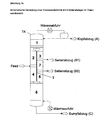
- a typical dividing wall column (TK) to be used in the process according to the invention in each case has a dividing wall (T) in the longitudinal direction of the column, forming an upper common column region (1), a lower common column region (6), an inlet part (2, 4) with reinforcement part (2) and stripping part (4), and a removal part ( 3, 5) with reinforcing part (5) and driven part (3), the feed of the mixture to be separated (feed) in the central region of the feed part (2, 4), the removal of the high boiler fraction via the bottom (bottom draw C), the discharge of the Low boiler fraction over head (topping A) and the removal of the medium boiler fraction from the central region of the removal part (3, 5) (side draw B) takes place.
- the dividing wall columns of the process according to the invention preferably have in each case from 30 to 100, in particular from 50 to 90, theoretical plates.
- the mixture comprising alkanolamines is worked up in dividing wall columns in which the alkanolamine (s) are obtained as side draw-off products, preferably with a purity of> 98.0% by weight, particularly ⁇ 99.0% by weight.
- the operating pressure of the columns is preferably in the range of 0.001 to 5 bar, particularly preferably 0.01 to 2 bar, more preferably 0.1 to 1.6 bar.
- Operating pressure in this document means the absolute pressure measured at the top of the column.
- the separation is carried out in two successive dividing wall columns, wherein the bottom draw stream of the first dividing wall column forms the feed stream for the second dividing wall column.
- the dividing wall columns (TK) are preceded by a conventional distillation column (K), in which lighter boilers are separated off via the top, the bottom draw stream forming the feed stream for the first dividing wall column.
- the upper common column region (1) of the dividing wall columns (TK) has 5 to 50%, preferably 20 to 35%, the reinforcing part (2) of the feed part (2, 4) of the column 5 to 50%, preferably 10 to 20%, the stripping section (4) of the feed section of the column 5 to 50%, preferably 20 to 35%, the reinforcing part (3) of the removal part (3, 5) of the column 5 to 50%, preferably 7 to 20%, the stripping section (5) of the removal part of the column 5 to 50%, preferably 20 to 35%, and the common lower portion (6) of the column 5 to 50%, preferably 20 to 35%, of the total number of theoretical plates (nth) of the column ,
- dividing wall columns (TK) in each case the sum of the number of theoretical plates of subregions (2) and (4) in the feed section 80 to 110%, preferably 90 to 100%, the sum of the number of stages of the subregions (3) and (5) in the sampling section.
- the inventive method is preferably characterized in that the feed point and the Soabzugsstelle the dividing wall columns for the separation of alkanolamine / s with respect to the position of the theoretical plates at different heights in the column are arranged by the feed point by 1 to 20, in particular 5 to 15 , theoretical plates different from the side trigger.
- the subregion of the dividing wall columns (TK) subdivided by the dividing wall (T) is preferably composed of the subregions 2, 3, 4 and 5 or parts thereof ordered packings or packing fitted and the partition in these sub-areas preferably designed to be heat-insulating.
- the alkanolamine or the alkanolamines are / are removed at the side take-off point in liquid form or in gaseous form.
- the vapor stream at the lower end of the partition walls (T) by the choice and / or dimensioning of Tiretrbauten and / or the installation pressure loss generating devices, such as diaphragms, adjusted so that the ratio of the vapor stream in the inlet part to that of the sampling 0.8 to 1.2, in particular 0.9 to 1.1, is.
- ratios referred to in this document with respect to certain streams refer to the weight.
- the liquid draining from the upper common area (1) of the dividing wall columns is collected in a collecting space arranged in the column or outside the column and deliberately divided by a fixed setting or regulation at the upper end of the dividing wall (T) such that the ratio of the liquid flow to the inlet part to the removal part to 0.1 to 2.0, in particular 0.1 to 1.0, z. B. 0.25 to 0.8, is.
- the liquid is preferably conveyed to the inlet part 2 via a pump or volume controlled via a static inlet height of at least 1 m and the control is adjusted so that the amount of liquid applied to the inlet part does not fall below 30% of the normal value.
- the dividing wall columns (TK) have sampling possibilities at the upper and lower end of the dividing wall (T) and samples are withdrawn from the columns continuously or at intervals in liquid or gaseous form and examined with respect to their composition.
- Compliance with the specification for the high boilers in the medium boiler fraction is preferably controlled by the distribution ratio of the liquid at the top of the partition.
- the distribution ratio of the liquid at the upper end of the partition walls (T) is adjusted so that the concentration of the key components for the high boiler fraction in the liquid at the upper end of the partition is 5 to 75%, preferably 10 to 40%, of the value Seitabzugs. is to be achieved, and the liquid distribution is set so that at higher levels of key components of the high boiler fraction more and at lower levels of key components of the high boiler fraction less liquid is directed to the inlet part.
- the specification for the low boilers in the medium boiler fraction is preferably regulated by the heating power.
- the heating power in the evaporator of the respective dividing wall column is adjusted so that the concentration of key components of the low boiler fraction in the liquid at the lower end of the partition walls (T) 10 to 99%, preferably 25 to 97.5%, of the value makes up in the soabzugs. is to be achieved, and the heating power is adjusted so that the higher the content of key components of the low boiler fraction increases the heating power and the lower content of key components of the low boiler fraction, the heating power is reduced.
- the one by actuators For example, allow valves, regulated fluid transfer.
- the liquid is first collected in collectors and from there into an internal or external collecting space.
- the inventive method is preferably characterized in that the distillate removal takes place temperature-controlled and is used as a control temperature, a measuring point in the sub-area 1 of the dividing wall column, which by 2 to 20, in particular 4 to 15, theoretical plates is located below the top of the column.
- the inventive method is preferably characterized in that the withdrawal of the bottom product takes place temperature-controlled and is used as control temperature a measuring point in the section 6 of the dividing wall column, which is arranged by 2 to 20, in particular 4 to 15, theoretical plates above the lower end of the column.
- the removal of the side product in the side take-off is controlled in a controlled manner, and the liquid level in the evaporator is used as the controlled variable.
- the partitions are not welded into the column, but are designed in the form of loosely inserted and adequately sealed sub-segments.
- a further variation of the process according to the invention for the distillative workup of the alkanolamines is that, instead of one of the dividing wall columns, which are to be preferred in a new building in terms of investment costs, an interconnection of two (conventional) distillation columns in the form of a thermal coupling is used (thermally coupled Columns corresponding to the energy requirement of a dividing wall column). This is especially beneficial if the columns are already present and / or the columns are to be operated at different pressures.
- both thermally coupled distillation columns are each equipped with its own evaporator and condenser.
- the two thermally coupled columns are preferably operated at different pressures and promoted only liquids in the connecting streams between the two columns. It is thus possible to choose circuit forms which allow only liquid connection streams to occur between the individual distillation columns.
- These special interconnections offer the advantage that the two distillation columns can be operated under different pressures with the advantage that they can be better adapted to the temperature levels of existing heating and cooling energies.
- the bottom stream of the first column of the two thermally coupled columns is partially or completely evaporated in an additional evaporator and then fed to the second column two-phase or in the form of a gaseous and a liquid stream.
- the feed stream (feed) to the column (s) is preferably partially or completely pre-evaporated and fed to the column (s) in two-phase or gaseous and liquid streams.
- Dividing wall columns and thermally coupled columns can be designed as packed columns with random packings or ordered packings or as tray columns.
- the present invention also provides a device for the continuous distillative separation of a mixture comprising monoisopropanolamine (MIPOA), diisopropanolamine (DIPOA) and triisopropanolamine (TIPOA), characterized by a configuration and column interconnection as defined above and in particular in the example given below.
- MIPOA monoisopropanolamine
- DIPOA diisopropanolamine
- TIPOA triisopropanolamine
- the invention relates to a device suitable for the separation of a mixture comprising monoisopropanolamine (MIPOA), diisopropanolamine (DIPOA) and triisopropanolamine (TIPOA), with a conventional distillation column (K 1), having a feed in the middle region, a top draw, which preferably leads to the reaction of PO with ammonia, a bottom draw, a feed of the bottom draw in the longitudinally divided region of a dividing wall column (TK 2), having a side draw for MIPOA in the longitudinally divided region, a top draw, which preferably leads to the reaction of PO with ammonia, a Bottom take-off, a feed of the bottom take-off from TK 2 in the longitudinally divided region of a dividing wall column (TK 3), comprising a side draw for DIPOA sym / asym mixture in the longitudinally divided region, a side draw for DIPOA-sym in the upper column region (1), a top draw and
- the APHA measurements were carried out in accordance with DIN ISO 6271.
- IPA isopropanolamines
- MIPOA monoisopropanolamine
- DIPOAsym and DIPOAasym diisopropanolamines
- TIPOA triisopropanolamine
- NH 3 and water are mixed and fed together with propylene oxide (PO) the tube reactor (55 bar, 110-140 ° C).
- PO propylene oxide
- Water-catalyzed liquid-phase synthesis of NH 3 with PO to IPOA is exothermic via a series of irreversible sequential reactions of NH 3 via MIPOA and DIPOA to TIPOA.
- the tubular reactor is divided into several cooling and heating zones. To dissipate the heat of reaction, the reactor is cooled in the first section with water and kept for complete reaction ( ⁇ 1 ppm PO) towards the end of the tube by heating to reaction temperature.
- the reaction is usually operated with a molar NH 3 excess between 3 and 8 in order to achieve the desired product mix MIPOA / DIPOA / TIPOA in a targeted manner.
- the mixing circuit about 20 wt .-% water are adjusted.
- K 1 (15 theoretical plates), water and excess NH 3 are separated overhead at a column pressure of 3 bar and returned to the mixing vessel.
- the bottom of K 1 forms the feed to the 1st dividing wall column TK 2 (50 theoretical plates).
- pure MIPOA is recovered at 200 mbar head pressure via a liquid side draw beyond the dividing wall and residual water is recycled overhead.
- the product mix can also be shifted by targeted recycling of DIPA towards TIPA (TIPA-rich mode of operation).
Description
Die vorliegende Erfindung betrifft eine Vorrichtung und ein Verfahren zur kontinuierlichen destillativen Auftrennung eines Gemisches enthaltend Monoisopropanolamin (MIPOA), Diisopropanolamin (DIPOA) und Triisopropanolamin (TIPOA).The present invention relates to an apparatus and a process for the continuous distillative separation of a mixture containing monoisopropanolamine (MIPOA), diisopropanolamine (DIPOA) and triisopropanolamine (TIPOA).
Für die destillative, z. B. kontinuierliche Zerlegung von Mehrstoffgemischen sind verschiedene Verfahrensvarianten gebräuchlich. Im einfachsten Fall wird das aufzutrennende Gemisch (Zulaufgemisch) in zwei Fraktionen, eine leichtsiedende Kopffraktion und eine schwersiedende Sumpffraktion, zerlegt.For the distillative, z. B. continuous decomposition of multicomponent mixtures are different process variants in use. In the simplest case, the mixture to be separated (feed mixture) is decomposed into two fractions, a low-boiling overhead fraction and a high-boiling bottom fraction.
Bei der Auftrennung von Zulaufgemischen in mehr als zwei Fraktionen müssen nach dieser Verfahrensvariante mehrere Destillationskolonnen eingesetzt werden. Um den apparativen Aufwand zu begrenzen, setzt man bei der Auftrennung von Vielstoffgemischen nach Möglichkeit Kolonnen mit flüssigen oder dampfförmigen Seitenabzügen ein.In the separation of feed mixtures into more than two fractions, a plurality of distillation columns must be used according to this process variant. In order to limit the expenditure on equipment, it is possible in the separation of multi-component mixtures, if possible, columns with liquid or vapor side draws.
Die Anwendungsmöglichkeit von Destillationskolonnen mit Seitenabzügen ist jedoch dadurch stark eingeschränkt, dass die an den Seitenabzugsstellen entnommenen Produkte selten oder nie völlig rein sind. Bei Seitenentnahmen im Verstärkungsteil der Kolonne, die üblicherweise in flüssiger Form erfolgen, enthält das Seitenprodukt noch Anteile an leichtsiedenden Komponenten, die über Kopf abgetrennt werden sollen. Entsprechendes gilt für Seitenentnahmen im Abtriebsteil der Kolonne, die meist dampfförmig erfolgen, bei denen das Seitenprodukt noch Hochsiederanteile aufweist.However, the application of distillation columns with side draws is severely limited by the fact that the products taken off at the side draw-off points are seldom or never completely pure. In side withdrawals in the enrichment section of the column, which usually take place in liquid form, the side product still contains portions of low-boiling components which are to be separated off via the top. The same applies to side withdrawals in the stripping section of the column, which usually take place in vapor form, in which the side product still has high boilers.
Die Verwendung von konventionellen Seitenabzugskolonnen ist daher auf Fälle begrenzt, in denen verunreinigte Seitenprodukte zulässig sind.The use of conventional side draw columns is therefore limited to cases where contaminated side products are allowed.
Eine Abhilfemöglichkeit bieten Trennwandkolonnen, bei denen auch die Seitenprodukte in hoher Reinheit gewonnen werden können (siehe z. B.
-
US 2,471,134 US 4,230 533 EP 122 367 A EP 126 288 A EP 133 510 A -
Chem. Eng. Technol. 10, (1987), Seiten 92 - 98 -
Chem.-Ing.-Tech. 61, (1989), Nr. 1, Seiten 16 - 25 -
Gas Separation and Purification 4 (1990), Seiten 109 - 114 -
Process Engineering 2 (1993), Seiten 33 - 34 -
Trans IChemE 72 (1994), Part A, Seiten 639 - 644 -
Chemical Engineering 7 (1997), 72 - 76
-
US 2,471,134 US 4,230 533 EP 122 367 A EP 126 288 A EP 133 510 A -
Chem. Eng. Technol. 10, (1987), pages 92-98 -
Chem-Ing.-Tech. 61, (1989), No. 1, pages 16-25 -
Gas Separation and Purification 4 (1990), pages 109-114 -
Process Engineering 2 (1993), pages 33-34 -
Trans IChemE 72 (1994), Part A, pp. 639-644 -
Chemical Engineering 7 (1997), 72-76
Bei dieser Bauart ist im mittleren Bereich oberhalb und unterhalb der Zulaufstelle und der Seitenentnahme eine Trennwand angebracht, die den Zulaufteil 2, 4 gegenüber dem Entnahmeteil 3, 5 abdichtet und in diesem Kolonnenteil eine Quervermischung von Flüssigkeits- und Brüdenströmen unterbindet. Hierdurch verringert sich bei der Auftrennung von Vielstoffgemischen die Zahl der insgesamt benötigten Destillationskolonnen. Wie bei konventionellen Seitenabzugskolonnen können auch bei Trennwandkolonnen Zwischenverdampfer und Zwischenkondensatoren eingesetzt werden. Zwischenkondensatoren werden bevorzugt am oberen Ende der Trennwand oder im gemeinsamen Kolonnenbereich 1 oberhalb der Trennwand angebracht. Zwischenverdampfer werden bevorzugt am unteren Ende der Trennwand oder im gemeinsamen Kolonnenbereich 6 unterhalb der Trennwand vorgesehen.In this design, a partition wall is mounted in the middle region above and below the feed point and the side removal, which seals the
Eine Trennwandkolonne kann bei gleichem Energieverbrauch auch durch die Anordnung von thermisch gekoppelten Destillationskolonnen ersetzt werden. Eine Beschreibung von thermisch gekoppelten Destillationskolonnen, die in verschiedener apparativer Gestaltung ausgeführt sein können, findet sich ebenfalls in den oben genannten Stellen in der Fachliteratur. Es ist auch möglich, die einzelnen Teilkolonnen komplett mit Verdampfern und Kondensatoren auszurüsten. Dies entspricht einer Trennwandkolonne mit einem Zwischenverdampfer und einem Zwischenkondensator. Ein besonderer Vorteil dieser speziellen Ausgestaltung ist, dass die einzelnen Kolonnen auch bei unterschiedlichen Drücken betrieben werden können. Dies ermöglicht es, zu hohe Temperaturspreizungen zu vermeiden und die Betriebstemperaturen besser an vorgegebene Heiz- und Kühlmedien anzupassen. Die Möglichkeiten für Energieverbundmaßnahmen werden verbessert.A dividing wall column can be replaced with the same energy consumption by the arrangement of thermally coupled distillation columns. A description of thermally coupled distillation columns, which may be embodied in various apparatus design, can also be found in the abovementioned points in the specialist literature. It is also possible to equip the individual sub-columns completely with evaporators and condensers. This corresponds to a dividing wall column with an intermediate evaporator and an intermediate condenser. A particular advantage of this particular embodiment is that the individual columns can also be operated at different pressures. This makes it possible to avoid too high temperature spreads and to better adapt the operating temperatures to given heating and cooling media. The possibilities for energy interconnections are improved.
In einer speziellen Ausgestaltung können bei Trennwandkolonnen und thermisch gekoppelten Destillationskolonnen statt einer auch zwei reine Seitenfraktionen entnommen werden. Der Entnahmeteil 3, 5 wird durch einen zwischengeschalteten Kolonnenbereich 7 erweitert (
Eine weitere Bauform von erfindungsgemäß einsetzbaren Trennwandkolonnen sieht vor, die Trennwand durchgehend entweder bis zum oberen oder unteren Ende der Destillationskolonne auszuführen (
Trennwandkolonnen und thermisch gekoppelte Destillationskolonnen bieten gegenüber der Anordnung von konventionellen Destillationskolonnen sowohl hinsichtlich des Energiebedarfs als auch der Investitionskosten Vorteile.Dividing wall columns and thermally coupled distillation columns offer advantages over the arrangement of conventional distillation columns both in terms of energy requirements and investment costs.
Für die Regelung von Trennwandkolonnen und thermisch gekoppelten Kolonnen werden verschiedene Regelungsstrategien beschrieben. Beschreibungen finden sich in:
-
US 4,230,533 DE 35 22 234 C2 EP 780 147 A -
Process Engineering 2 (1993), 33 - 34 -
Ind. Eng. Chem. Res. 34 (1995), 2094-2103
-
US 4,230,533 DE 35 22 234 C2 EP 780 147 A -
Process Engineering 2 (1993), 33-34 -
Ind. Eng. Chem. Res. 34 (1995), 2094-2103
Der vorliegenden Erfindung lag die Aufgabe zugrunde, ein verbessertes wirtschaftliches Verfahren zur Auftrennung eines Gemisches enthaltend Monoisopropanolamin (MIPOA), Diisopropanolamin (DIPOA) und Triisopropanolamin (TIPOA) aufzufinden. Die einzelnen Alkanolamine, Monoisopropanolamin (MIPOA), Diisopropanolamin (DIPOA) und Triisopropanolamin (TIPOA), sollten dabei jeweils in hoher Reinheit und unter Einhaltung weiterer Spezifikationsmerkmale, insbesondere Farbqualität, anfallen.It is an object of the present invention to provide an improved economical process for the separation of a mixture containing monoisopropanolamine (MIPOA), diisopropanolamine (DIPOA) and triisopropanolamine (TIPOA). The individual alkanolamines, monoisopropanolamine (MIPOA), diisopropanolamine (DIPOA) and triisopropanolamine (TIPOA) should in each case be obtained in high purity and in compliance with further specification features, in particular color quality.
Demgemäß wurde ein Verfahren zur kontinuierlichen destillativen Auftrennung eines Gemisches enthaltend Monoisopropanolamin (MIPOA), Diisopropanolamin (DIPOA) und Triisopropanolamin (TIPOA) gefunden, welches dadurch gekennzeichnet ist, dass in einer konventionellen Destillationskolonne (K 1) Leichtersieder über Kopf und ein Gemisch enthaltend die Isopropanolamine über Sumpf abgetrennt werden, wobei Letzteres einer ersten Trennwandkolonne (TK 2) weiter aufgearbeitet wird, in der MIPOA als Seitenabzugsstrom aus dem längsunterteilten Bereich und ein Gemisch enthaltend DIPOA und TIPOA über Sumpf abgetrennt werden, wobei Letzteres in einer zweiten Trennwandkolonne (TK 3) weiter aufgearbeitet wird, in der DIPOA als Seitenabzugsstrom aus dem längsunterteilten Bereich und TIPOA über Sumpf gewonnen werden. Siehe
In alternativen Ausführungsformen kann anstelle einer Trennwandkolonne eine Zusammenschaltung von zwei (konventionellen) Destillationskolonnen in Form einer thermischen Kopplung verwendet werden.In alternative embodiments, an interconnection of two (conventional) distillation columns in the form of a thermal coupling may be used instead of a dividing wall column.
Bei den ab- und aufzutrennenden Alkanolaminen handelt es sich um Monoisopropanolamin (MIPOA), Diisopropanolamin (DIPOA) und Triisopropanolamin (TIPOA).The alkanolamines to be separated and separated are monoisopropanolamine (MIPOA), diisopropanolamine (DIPOA) and triisopropanolamine (TIPOA).
Die Herstellung dieser Gemische kann nach verschiedenen in der Fachliteratur beschriebenen Verfahren erfolgen. Bei den Herstellverfahren wird Ammoniak z. B. im einbis zwanzigfachen molaren Überschuss bezogen auf Propylenoxid eingesetzt. Das Austragsgemisch dieser Umsetzungen, bestehend überwiegend aus ggf. unumgesetztem Ammoniak, ggf. Wasser, einem oder mehreren Alkanolaminen und Nebenprodukten, wird zunächst entspannt und ausgegast, anschließend werden Ammoniak und Wasser, jeweils teilweise oder vollständig, destillativ abgetrennt.The preparation of these mixtures can be carried out according to various methods described in the specialist literature. In the manufacturing process ammonia z. B. in one to twenty times the molar excess based on propylene oxide. The discharge mixture of these reactions, consisting predominantly of possibly unreacted ammonia, optionally water, one or more alkanolamines and by-products, is first depressurized and outgassed, then ammonia and water, in each case partially or completely, are separated off by distillation.
Es wurde gefunden, dass die weitere destillative Aufarbeitung und spezifikationsgerechte Reingewinnung des Alkanolamis oder der Alkanolamine besonders vorteilhaft hinsichtlich der Produktqualität gelingt, wenn die Aufarbeitung in Trennwandkolonnen oder thermisch gekoppelten Destillationskolonnen erfolgt und das/die Alkanolamin/e als Seitenfraktion/en entnommen werden. Diese Verfahrensgestaltung ermöglicht zudem niedrige Investitionskosten und einen geringen Energieverbrauch.It has been found that the further work-up by distillation and specification-compliant purification of the alkanolamines or alkanolamines is particularly advantageous in terms of product quality when working up in dividing wall columns or thermally coupled distillation columns and the alkanolamine (s) are taken off as side fraction (s). This process design also allows low investment costs and low energy consumption.
Eine typische, im erfindungsgemäßen Verfahren anzuwendende Trennwandkolonne (TK) (siehe
Die Trennwandkolonnen des erfindungsgemäßen Verfahrens weisen jeweils bevorzugt 30 bis 100, insbesondere 50 bis 90, theoretische Trennstufen auf.The dividing wall columns of the process according to the invention preferably have in each case from 30 to 100, in particular from 50 to 90, theoretical plates.
Das Gemisch enthaltend Alkanolamine wird in Trennwandkolonnen aufgearbeitet, in denen das/die Alkanolamin/e als Seitenabzugsprodukte bevorzugt mit einer Reinheit > 98,0 Gew.-%, besonders ≥ 99,0 % Gew.-%, gewonnen werden.The mixture comprising alkanolamines is worked up in dividing wall columns in which the alkanolamine (s) are obtained as side draw-off products, preferably with a purity of> 98.0% by weight, particularly ≥99.0% by weight.
Der Betriebsdruck der Kolonnen liegt bevorzugt im Bereich von 0,001 bis 5 bar, besonders bevorzugt 0,01 bis 2 bar, weiter besonders bevorzugt 0,1 bis 1,6 bar.The operating pressure of the columns is preferably in the range of 0.001 to 5 bar, particularly preferably 0.01 to 2 bar, more preferably 0.1 to 1.6 bar.
Unter Betriebsdruck ist in diesem Dokument der am Kopf der Kolonne gemessene absolute Druck zu verstehen.Operating pressure in this document means the absolute pressure measured at the top of the column.
Die Auftrennung wird in zwei hintereinandergeschalteten Trennwandkolonnen durchgeführt, wobei der Sumpfabzugstrom der ersten Trennwandkolonne den Zulaufstrom für die zweite Trennwandkolonne bildet.The separation is carried out in two successive dividing wall columns, wherein the bottom draw stream of the first dividing wall column forms the feed stream for the second dividing wall column.
Den Trennwandkolonnen (TK) ist eine konventionelle Destillationskolonne (K) vorgeschaltet, in der Leichtersieder über Kopf abgetrennt werden, wobei der Sumpfabzugstrom den Zulaufstrom für die erste Trennwandkolonne bildet.The dividing wall columns (TK) are preceded by a conventional distillation column (K), in which lighter boilers are separated off via the top, the bottom draw stream forming the feed stream for the first dividing wall column.
Insbesondere weist im erfindungsgemäßen Verfahren der obere gemeinsame Kolonnenbereich (1) der Trennwandkolonnen (TK) 5 bis 50 %, bevorzugt 20 bis 35 %, der Verstärkungsteil (2) des Zulaufteils (2, 4) der Kolonne 5 bis 50 %, bevorzugt 10 bis 20 %, der Abtriebsteil (4) des Zulaufteils der Kolonne 5 bis 50 %, bevorzugt 20 bis 35 %, der Verstärkungsteil (3) des Entnahmeteils (3, 5) der Kolonne 5 bis 50 %, bevorzugt 7 bis 20 %, der Abtriebsteil (5) des Entnahmeteils der Kolonne 5 bis 50 %, bevorzugt 20 bis 35 %, und der gemeinsame untere Bereich (6) der Kolonne 5 bis 50 %, bevorzugt 20 bis 35 %, der Gesamtzahl der theoretischen Trennstufen (nth) der Kolonne auf.In particular, in the process according to the invention, the upper common column region (1) of the dividing wall columns (TK) has 5 to 50%, preferably 20 to 35%, the reinforcing part (2) of the feed part (2, 4) of the
Insbesondere beträgt in den Trennwandkolonnen (TK) jeweils die Summe der Zahl der theoretischen Trennstufen der Teilbereiche (2) und (4) im Zulaufteil 80 bis 110 %, bevorzugt 90 bis 100 %, der Summe der Zahl der Trennstufen der Teilbereiche (3) und (5) im Entnahmeteil.In particular, in the dividing wall columns (TK) in each case the sum of the number of theoretical plates of subregions (2) and (4) in the feed section 80 to 110%, preferably 90 to 100%, the sum of the number of stages of the subregions (3) and (5) in the sampling section.
Das erfindungsgemäße Verfahren ist bevorzugt dadurch gekennzeichnet, dass die Zulaufstelle und die Seitenabzugsstelle der Trennwandkolonnen zur Abtrennung von Alkanolamin/en hinsichtlich der Lage der theoretischen Trennstufen auf unterschiedlicher Höhe in der Kolonne angeordnet sind, indem sich die Zulaufstelle um 1 bis 20, insbesondere 5 bis 15, theoretische Trennstufen von der Seitenabzugsstelle unterscheidet.The inventive method is preferably characterized in that the feed point and the Seitenabzugsstelle the dividing wall columns for the separation of alkanolamine / s with respect to the position of the theoretical plates at different heights in the column are arranged by the feed point by 1 to 20, in particular 5 to 15 , theoretical plates different from the side trigger.
Falls besonders hohe Anforderungen an die Reinheiten der Produkte gestellt werden, ist es günstig, die Trennwand mit einer thermischen Isolierung auszustatten. Eine Beschreibung der verschiedenen Möglichkeiten der thermischen Isolierung der Trennwand findet sich z. B. in
Bevorzugt ist der durch die Trennwand (T) unterteilte Teilbereich der Trennwandkolonnen (TK) bestehend aus den Teilbereichen 2, 3, 4 und 5 oder Teilen davon mit geordneten Packungen oder Füllkörpern bestückt und die Trennwand in diesen Teilbereichen bevorzugt wärmeisolierend ausgeführt.The subregion of the dividing wall columns (TK) subdivided by the dividing wall (T) is preferably composed of the
Im erfindungsgemäßen Verfahren wird/werden das Alkanolamin bzw. die Alkanolamine an der Seitenabzugsstelle in flüssiger Form oder gasförmig entnommen.In the process according to the invention, the alkanolamine or the alkanolamines are / are removed at the side take-off point in liquid form or in gaseous form.
Bevorzugt wird der Brüdenstrom am unteren Ende der Trennwände (T) durch die Wahl und/oder Dimensionierung der Trenneinbauten und/oder den Einbau druckverlusterzeugender Vorrichtungen, beispielsweise von Blenden, so eingestellt, dass das Verhältnis des Brüdenstroms im Zulaufteil zu dem des Entnahmeteils 0,8 bis 1,2, insbesondere 0,9 bis 1,1, beträgt.Preferably, the vapor stream at the lower end of the partition walls (T) by the choice and / or dimensioning of Trennentrbauten and / or the installation pressure loss generating devices, such as diaphragms, adjusted so that the ratio of the vapor stream in the inlet part to that of the sampling 0.8 to 1.2, in particular 0.9 to 1.1, is.
Die in diesem Dokument genannten Verhältnisse bezüglich bestimmter Ströme (z. B. Flüssigkeitsströme, Brüdenströme, Sumpfströme, Zulaufströme, Seitenabzugsströme) beziehen sich auf das Gewicht.The ratios referred to in this document with respect to certain streams (eg liquid streams, vapor streams, bottom streams, feed streams, side bleed streams) refer to the weight.
Bevorzugt wird die aus dem oberen gemeinsamen Bereich (1) der Trennwandkolonnen ablaufende Flüssigkeit in einem in der Kolonne oder außerhalb der Kolonne angeordneten Auffangraum gesammelt und gezielt durch eine Festeinstellung oder Regelung am oberen Ende der Trennwand (T) so aufgeteilt, dass das Verhältnis des Flüssigkeitsstroms zum Zulaufteil zu dem zum Entnahmeteil 0,1 bis 2,0, insbesondere 0,1 bis 1,0, z. B. 0,25 bis 0,8, beträgt.Preferably, the liquid draining from the upper common area (1) of the dividing wall columns is collected in a collecting space arranged in the column or outside the column and deliberately divided by a fixed setting or regulation at the upper end of the dividing wall (T) such that the ratio of the liquid flow to the inlet part to the removal part to 0.1 to 2.0, in particular 0.1 to 1.0, z. B. 0.25 to 0.8, is.
Im erfindungsgemäßen Verfahren wird bevorzugt die Flüssigkeit auf den Zulaufteil 2 über eine Pumpe gefördert oder über eine statische Zulaufhöhe von mindestens 1 m mengengeregelt aufgegeben und die Regelung so eingestellt, dass die auf den Zulaufteil aufgegebene Flüssigkeitsmenge nicht unter 30 % des Normalwertes sinkt.In the method according to the invention, the liquid is preferably conveyed to the
Im erfindungsgemäßen Verfahren wird bevorzugt die Aufteilung der aus dem Teilbereich 3 im Entnahmeteil der Trennwandkolonne ablaufenden Flüssigkeit auf den Seitenabzug und auf den Teilbereich 5 im Entnahmeteil der Kolonne durch eine Regelung, z. B. im Prozessleitsystem, so eingestellt, dass die auf den Teilbereich 5 aufgegebene Flüssigkeitsmenge nicht unter 30 % des Normalwertes sinkt.In the method according to the invention, it is preferable to divide the liquid draining from the
Bevorzugt ist weiterhin, dass die Trennwandkolonnen (TK) am oberen und unteren Ende der Trennwand (T) Probenahmemöglichkeiten aufweisen und aus den Kolonnen kontinuierlich oder in zeitlichen Abständen flüssig oder gasförmig Proben entnommen und hinsichtlich ihrer Zusammensetzung untersucht werden.It is furthermore preferred that the dividing wall columns (TK) have sampling possibilities at the upper and lower end of the dividing wall (T) and samples are withdrawn from the columns continuously or at intervals in liquid or gaseous form and examined with respect to their composition.
Bei der Trennung von Mehrstoffgemischen in eine Leichtsieder-, Mittelsieder- und Hochsiederfraktion existieren üblicherweise Spezifikationen über den maximal zulässigen Anteil an Leichtsiedern und Hochsiedern in der Mittelsiederfraktion. Hierbei werden entweder einzelne für das Trennproblem kritische Komponenten, sogenannte Schlüsselkomponenten, oder die Summe von mehreren Schlüsselkomponenten spezifiziert.When separating multicomponent mixtures into a low-boiling, medium-high and high-boiling fractions, there are usually specifications for the maximum permissible fraction of low-boiling and high-boiling fractions in the medium boiler fraction. Here are either specifying individual components critical to the separation problem, called key components, or the sum of several key components.
Die Einhaltung der Spezifikation für die Hochsieder in der Mittelsiederfraktion wird bevorzugt über das Aufteilungsverhältnis der Flüssigkeit am oberen Ende der Trennwand geregelt. Dabei wird das Aufteilungsverhältnis der Flüssigkeit am oberen Ende der Trennwände (T) so eingestellt, dass die Konzentration der Schlüsselkomponenten für die Hochsiederfraktion in der Flüssigkeit am oberen Ende der Trennwand 5 bis 75 %, bevorzugt 10 bis 40 %, des Wertes ausmacht, der im Seitenabzugsprodukt erzielt werden soll, und die Flüssigkeitsaufteilung dahingehend eingestellt wird, dass bei höheren Gehalten an Schlüsselkomponenten der Hochsiederfraktion mehr und bei niedrigeren Gehalten an Schlüsselkomponenten der Hochsiederfraktion weniger Flüssigkeit auf den Zulaufteil geleitet wird.Compliance with the specification for the high boilers in the medium boiler fraction is preferably controlled by the distribution ratio of the liquid at the top of the partition. In this case, the distribution ratio of the liquid at the upper end of the partition walls (T) is adjusted so that the concentration of the key components for the high boiler fraction in the liquid at the upper end of the partition is 5 to 75%, preferably 10 to 40%, of the value Seitabzugsprodukt is to be achieved, and the liquid distribution is set so that at higher levels of key components of the high boiler fraction more and at lower levels of key components of the high boiler fraction less liquid is directed to the inlet part.
Entsprechend wird die Spezifikation für die Leichtsieder in der Mittelsiederfraktion bevorzugt durch die Heizleistung geregelt. Hierbei wird die Heizleistung im Verdampfer der jeweiligen Trennwandkolonne so eingestellt, dass die Konzentration an Schlüsselkomponenten der Leichtsiederfraktion in der Flüssigkeit am unteren Ende der Trennwände (T) 10 bis 99 %, bevorzugt 25 bis 97,5 %, des Wertes ausmacht, der im Seitenabzugsprodukt erzielt werden soll, und die Heizleistung dahingehend eingestellt wird, dass bei höherem Gehalt an Schlüsselkomponenten der Leichtsiederfraktion die Heizleistung erhöht und bei niedrigerem Gehalt an Schlüsselkomponenten der Leichtsiederfraktion die Heizleistung verringert wird.Accordingly, the specification for the low boilers in the medium boiler fraction is preferably regulated by the heating power. In this case, the heating power in the evaporator of the respective dividing wall column is adjusted so that the concentration of key components of the low boiler fraction in the liquid at the lower end of the partition walls (T) 10 to 99%, preferably 25 to 97.5%, of the value makes up in the Seitenabzugsprodukt is to be achieved, and the heating power is adjusted so that the higher the content of key components of the low boiler fraction increases the heating power and the lower content of key components of the low boiler fraction, the heating power is reduced.
Zur Kompensation von Störungen der Zulaufmenge oder der Zulaufkonzentration erweist es sich zudem als vorteilhaft, durch entsprechende Regelvorschriften, z. B. im Prozessleitsystem, sicherzustellen, dass die Mengenströme der Flüssigkeiten, die auf die Kolonnenteile 2 und 5 (vgl.
Zur Entnahme und Aufteilung der Flüssigkeiten am oberen Ende der Trennwand und an der Seitenentnahmestelle eignen sich sowohl innenliegende als auch außerhalb der Kolonne angeordnete Auffangräume für die Flüssigkeit, die die Funktion einer Pumpenvorlage übernehmen oder für eine ausreichend hohe statische Flüssigkeitshöhe sorgen, die eine durch Stellorgane, beispielsweise Ventile, geregelte Flüssigkeitsweiterleitung ermöglichen. Bei der Verwendung von gepackten Kolonnen wird die Flüssigkeit zunächst in Sammlern gefasst und von dort aus in einen innenliegenden oder außenliegenden Auffangraum geleitet.For collecting and dividing the liquids at the upper end of the dividing wall and at the side extraction point, both internally and outside the column arranged collecting spaces for the liquid, which take over the function of a pump template or provide a sufficiently high static liquid level, the one by actuators, For example, allow valves, regulated fluid transfer. When using packed columns, the liquid is first collected in collectors and from there into an internal or external collecting space.
Das erfindungsgemäße Verfahren ist bevorzugt dadurch gekennzeichnet, dass die Destillatentnahme temperaturgeregelt erfolgt und als Regeltemperatur eine Messstelle im Teilbereich 1 der Trennwandkolonne verwendet wird, die um 2 bis 20, insbesondere 4 bis 15, theoretische Trennstufen unterhalb des oberen Endes der Kolonne angeordnet ist.The inventive method is preferably characterized in that the distillate removal takes place temperature-controlled and is used as a control temperature, a measuring point in the
Das erfindungsgemäße Verfahren ist bevorzugt dadurch gekennzeichnet, dass die Entnahme des Sumpfprodukts temperaturgeregelt erfolgt und als Regeltemperatur eine Messstelle im Teilbereich 6 der Trennwandkolonne verwendet wird, die um 2 bis 20, insbesondere 4 bis 15, theoretische Trennstufen oberhalb des unteren Endes der Kolonne angeordnet ist.The inventive method is preferably characterized in that the withdrawal of the bottom product takes place temperature-controlled and is used as control temperature a measuring point in the
In einer weiteren besonderen Ausgestaltung erfolgt die Entnahme des Seitenprodukts im Seitenabzug standgeregelt und als Regelgröße wird der Flüssigkeitsstand im Verdampfer verwendet.In a further particular embodiment, the removal of the side product in the side take-off is controlled in a controlled manner, and the liquid level in the evaporator is used as the controlled variable.
Bevorzugt ist, dass die Trennwände nicht in die Kolonne eingeschweißt sind, sondern in Form von lose gesteckten und adäquat abgedichteten Teilsegmenten gestaltet sind.It is preferred that the partitions are not welded into the column, but are designed in the form of loosely inserted and adequately sealed sub-segments.
Eine weitere erfindungsgemäße Variation des Verfahrens zur destillativen Aufarbeitung der Alkanolamine besteht darin, dass anstelle einer der genannten Trennwandkolonnen - die bei einem Neubau hinsichtlich der Investitionskosten zu bevorzugen sind - eine Zusammenschaltung von zwei (konventionellen) Destillationskolonnen in Form einer thermischen Kopplung verwendet wird (thermisch gekoppelte Kolonnen, die hinsichtlich des Energiebedarfs einer Trennwandkolonne entsprechen).
Dies ist vor allem dann günstig, wenn die Kolonnen schon vorhanden sind und/oder die Kolonnen bei verschiedenen Drücken betrieben werden sollen.A further variation of the process according to the invention for the distillative workup of the alkanolamines is that, instead of one of the dividing wall columns, which are to be preferred in a new building in terms of investment costs, an interconnection of two (conventional) distillation columns in the form of a thermal coupling is used (thermally coupled Columns corresponding to the energy requirement of a dividing wall column).
This is especially beneficial if the columns are already present and / or the columns are to be operated at different pressures.
Je nach der Trennstufenzahl der vorhandenen Kolonnen können die geeignetsten Formen der Zusammenschaltung gewählt werden.
Bevorzugt sind beide thermisch gekoppelten Destillationskolonnen jeweils mit einem eigenen Verdampfer und Kondensator ausgestattet.Depending on the number of separation stages of the existing columns, the most suitable forms of interconnection can be selected.
Preferably, both thermally coupled distillation columns are each equipped with its own evaporator and condenser.
Weiterhin werden bevorzugt die beiden thermisch gekoppelten Kolonnen bei verschiedenen Drücken betrieben und in den Verbindungsströmen zwischen den beiden Kolonnen nur Flüssigkeiten gefördert.
Es ist also möglich, Schaltungsformen zu wählen, die es erlauben, dass nur flüssige Verbindungsströme zwischen den einzelnen Destillationskolonnen auftreten. Diese speziellen Verschaltungen bieten den Vorteil, dass die beiden Destillationskolonnen unter verschiedenen Drücken betrieben werden können mit dem Vorteil, dass sie sich besser an die Temperaturniveaus vorhandener Heiz- und Kühlenergien anpassen lassen.Furthermore, the two thermally coupled columns are preferably operated at different pressures and promoted only liquids in the connecting streams between the two columns.
It is thus possible to choose circuit forms which allow only liquid connection streams to occur between the individual distillation columns. These special interconnections offer the advantage that the two distillation columns can be operated under different pressures with the advantage that they can be better adapted to the temperature levels of existing heating and cooling energies.
Bevorzugt wird der Sumpfstrom der ersten Kolonne der beiden thermisch gekoppelten Kolonnen in einem zusätzlichen Verdampfer teilweise oder vollständig verdampft und anschließend der zweiten Kolonne zweiphasig oder in Form eines gasförmigen und eines flüssigen Stromes zugeführt.Preferably, the bottom stream of the first column of the two thermally coupled columns is partially or completely evaporated in an additional evaporator and then fed to the second column two-phase or in the form of a gaseous and a liquid stream.
Im erfindungsgemäßen Verfahren wird bevorzugt der Zulaufstrom (Feed) zur Kolonne/zu den Kolonnen teilweise oder vollständig vorverdampft und der/den Kolonne/n zweiphasig oder in Form eines gasförmigen und eines flüssigen Stromes zugeführt.In the process according to the invention, the feed stream (feed) to the column (s) is preferably partially or completely pre-evaporated and fed to the column (s) in two-phase or gaseous and liquid streams.
Trennwandkolonnen und thermisch gekoppelte Kolonnen können als Packungskolonnen mit Füllkörpern oder geordneten Packungen oder als Bodenkolonnen ausgeführt werden.Dividing wall columns and thermally coupled columns can be designed as packed columns with random packings or ordered packings or as tray columns.
Bei der erfindungsgemäßen Reindestillation der Alkanolamine, die bevorzugt im Vakuum betrieben wird, empfiehlt es sich, Packungskolonnen einzusetzen. Dabei sind geordnete Blechpackungen mit einer spezifischen Oberfläche von 100 bis 500 m2/m3, bevorzugt etwa 250 bis 350 m2/m3, besonders geeignet.In the case of the pure distillation of the alkanolamines according to the invention, which is preferably operated in vacuo, it is advisable to use packed columns. In this case, ordered sheet metal packings having a specific surface area of 100 to 500 m 2 / m 3 , preferably about 250 to 350 m 2 / m 3 , are particularly suitable.
Gegenstand der vorliegenden Erfindung ist auch eine Vorrichtung zur kontinuierlichen destillativen Auftrennung eines Gemisches enthaltend Monoisopropanolamin (MIPOA), Diisopropanolamin (DIPOA) und Triisopropanolamin (TIPOA), gekennzeichnet durch eine Ausgestaltung und Kolonnenverschaltung wie vorstehend und insbesondere in dem weiter unten aufgeführten Beispiel definiert und beschrieben.The present invention also provides a device for the continuous distillative separation of a mixture comprising monoisopropanolamine (MIPOA), diisopropanolamine (DIPOA) and triisopropanolamine (TIPOA), characterized by a configuration and column interconnection as defined above and in particular in the example given below.
In einer besonderen Ausgestaltung betrifft die Erfindung eine Vorrichtung, geeignet zur Auftrennung eines Gemisches enthaltend Monoisopropanolamin (MIPOA), Diisopropanolamin (DIPOA) und Triisopropanolamin (TIPOA), mit einer konventionellen Destillationskolonne (K 1), aufweisend einen Zulauf im mittleren Bereich, einen Kopfabzug, der bevorzugt zur Umsetzung von PO mit Ammoniak zurückführt, einen Sumpfabzug, einer Zuführung des Sumpfabzugs im längsunterteilten Bereich einer Trennwandkolonne (TK 2), aufweisend einen Seitenabzug für MIPOA im längsunterteilten Bereich, einen Kopfabzug, der bevorzugt zur Umsetzung von PO mit Ammoniak zurückführt, einen Sumpfabzug, einer Zuführung des Sumpfabzugs von TK 2 im längsunterteilten Bereich einer Trennwandkolonne (TK 3), aufweisend einen Seitenabzug für DIPOA-sym/asym-Gemisch im längsunterteilten Bereich, einen Seitenabzug für DIPOA-sym im oberen Kolonnenbereich (1), einen Kopfabzug und einen Sumpfabzug für TIPOA. Siehe Abbildung 2.In a particular embodiment, the invention relates to a device suitable for the separation of a mixture comprising monoisopropanolamine (MIPOA), diisopropanolamine (DIPOA) and triisopropanolamine (TIPOA), with a conventional distillation column (K 1), having a feed in the middle region, a top draw, which preferably leads to the reaction of PO with ammonia, a bottom draw, a feed of the bottom draw in the longitudinally divided region of a dividing wall column (TK 2), having a side draw for MIPOA in the longitudinally divided region, a top draw, which preferably leads to the reaction of PO with ammonia, a Bottom take-off, a feed of the bottom take-off from
Die APHA-Messungen erfolgten gemäß DIN ISO 6271.The APHA measurements were carried out in accordance with DIN ISO 6271.
Die Bestimmung von Wasser-Gehalten erfolgte standardgemäß durch Karl-Fischer-Titration.The determination of water contents was carried out by standard Karl Fischer titration.
Die Ermittlung der Reinheit von Alkanolaminen erfolgte nach vorheriger Derivatisierung mit Trifluoressigsäureanhydrid mittels Gaschromatographie wie folgt:
- IPOA: Säule: CP SIL 8 CB - 25 m - 0,32 mm - 5 µm FD
- IPOA: Column: CP SIL 8 CB - 25 m - 0.32 mm - 5 μm FD
Alle ppm-Angaben beziehen sich auf das Gewicht (Gew.-ppm).All ppm data refer to the weight (ppm by weight).
Auftrennung eines Gemisches enthaltend die Isopropanolamine (IPOA) Monoisopropanolamin (MIPOA), Diisopropanolamine (DIPOAsym und DIPOAasym) und Triisopropanolamin (TIPOA)Separation of a mixture containing the isopropanolamines (IPOA) monoisopropanolamine (MIPOA), diisopropanolamines (DIPOAsym and DIPOAasym) and triisopropanolamine (TIPOA)
Im Mischkreis (25 bar, 40°C) werden NH3 und Wasser gemischt und zusammen mit Propylenoxid (PO) dem Rohrreaktor (55 bar, 110-140 °C) zugeführt. Die wasserkatalysierte Synthese in der Flüssigphase von NH3 mit PO zu IPOA läuft exotherm über eine Reihe von irreversiblen Folgereaktionen von NH3 über MIPOA und DIPOA zu TIPOA. Der Rohrreaktor ist in mehrere Kühl- und Heizzonen unterteilt. Zur Abfuhr der Reaktionswärme wird der Reaktor im ersten Abschnitt mit Wasser gekühlt und zum vollständigen Reaktionsablauf (< 1 ppm PO) gegen Rohrende durch Beheizen auf Reaktionstemperatur gehalten. Die Reaktion wird üblicherweise mit einem molaren NH3-Überschuss zwischen 3 und 8 betrieben, um gezielt das gewünschte Produktmix MIPOA/DIPOA/TIPOA zu erzielen. Im Mischkreis werden ca. 20 Gew.-% Wasser eingestellt. Aus dem Reaktionsgemisch werden in der Druckkolonne K 1 (15 theoretische Trennstufen) Wasser und überschüssiges NH3 über Kopf bei einem Kolonnendruck von 3 bar abgetrennt und zum Mischbehälter zurückgeführt. Der Sumpf der K 1 bildet den Zulauf zur 1. Trennwandkolonne TK 2 (50 theoretische Trennstufen). In der TK 2 wird bei 200 mbar Kopfdruck reines MIPOA über einen flüssigen Seitenabzug jenseits der Trennwand gewonnen und restliches Wasser über Kopf recycelt. In der 2. Trennwandkolonne TK 3 (60 theoretische Trennstufen) werden simultan bei 10 mbar Kopfdruck reines DIPOAsym (sym = symmetrisch) über einen flüssigen Seitenabzug im trennwandfreien Verstärkungsteil reindestilliert, eine vorgegebene DI-POAasym/DIPOAsym-Mischung (asym = asymmetrisch) über einen flüssigen Seitenabzug jenseits der Trennwand gewonnen und reines TIPOA über Sumpf der TK 3 abgetrennt. Über Kopf der TK 3 werden Nebenkomponenten (NK) ausgeschleust. Um die spezifizierten Farbqualitäten der Isopropanolamine (IPOA) zu gewährleisten, sollen in den Kolonnen K 1, TK 2 und TK 3 Sumpftemperaturen von 200 °C nicht überschritten werden.In the mixing circuit (25 bar, 40 ° C) NH 3 and water are mixed and fed together with propylene oxide (PO) the tube reactor (55 bar, 110-140 ° C). Water-catalyzed liquid-phase synthesis of NH 3 with PO to IPOA is exothermic via a series of irreversible sequential reactions of NH 3 via MIPOA and DIPOA to TIPOA. The tubular reactor is divided into several cooling and heating zones. To dissipate the heat of reaction, the reactor is cooled in the first section with water and kept for complete reaction (<1 ppm PO) towards the end of the tube by heating to reaction temperature. The reaction is usually operated with a molar NH 3 excess between 3 and 8 in order to achieve the desired product mix MIPOA / DIPOA / TIPOA in a targeted manner. In the mixing circuit about 20 wt .-% water are adjusted. From the reaction mixture in the pressure column K 1 (15 theoretical plates), water and excess NH 3 are separated overhead at a column pressure of 3 bar and returned to the mixing vessel. The bottom of
Zusätzlich zur Variation des NH3-Überschusses kann der Produktmix auch durch gezieltes Rückführen von DIPA in Richtung TIPA verschoben werden (TIPA-reiche Fahrweise). In addition to varying the NH 3 excess, the product mix can also be shifted by targeted recycling of DIPA towards TIPA (TIPA-rich mode of operation).
Claims (27)
- A process for continuous distillative separation of a mixture comprising monoisopropanolamine (MIPOA), diisopropanolamine (DIPOA) and triisopropanolamine (TIPOA), wherein, in a conventional distillation column (C 1), relatively low boilers are removed via the top and a mixture comprising the isopropanolamines is removed via the bottom, the latter being worked up further in a first dividing wall column (DWC 2) in which MIPOA is removed as a side draw stream from the longitudinally divided region and a mixture comprising DIPOA and TIPOA via the bottom, the latter being worked up further in a second dividing wall column (DWC 3) in which DIPOA is obtained as a side draw stream from the longitudinally divided region and TIPOA via the bottom.
- The process according to claim 1, wherein the mixture comprising the alkanolamines is a product obtained by reacting propylene oxide (PO) with ammonia and subsequent partial or complete removal of unconverted ammonia, with or without water.
- The process according to either of the preceding claims, wherein the operating pressure of the columns is in the range from 0.001 to 5 bar.
- The process according to any one of the preceding claims, wherein the dividing wall column (DWC) in each case has a dividing wall (DW) in the longitudinal direction of the column to form an upper common column region (1), a lower common column region (6), a feed section (2, 4) comprising rectifying section (2) and stripping section (4), and a withdrawal section (3, 5) comprising rectifying section (5) and stripping section (3), the mixture to be separated (feed) being fed in in the middle region of the feed section (2, 4), the high boiler fraction being removed via the bottom (bottom draw C), the low boiler fraction being removed via the top (top draw A) and the medium boiler fraction being removed from the middle region of the withdrawal section (3, 5) (side draw B).
- The process according to any one of the preceding claims, wherein the dividing wall columns each have 30 to 100 theoretical plates.
- The process according to either of the preceding claims 4 and 5, wherein, in the dividing wall columns (DWC), the sum of the number of theoretical plates of subregions (2) and (4) in the feed section is in each case 80 to 110% of the sum of the number of plates of subregions (3) and (5) in the withdrawal section.
- The process according to any one of claims 4 to 6, wherein the upper common column region (1) of the dividing wall columns (DWC) for removal of alkanolamine or alkanolamines has 5 to 50%, the rectifying section (2) of the feed section (2, 4) of the dividing wall column 5 to 50%, the stripping section (4) of the feed section of the dividing wall column 5 to 50%, the rectifying section (3) of the withdrawal section (3, 5) of the dividing wall column 5 to 50%, the stripping section (5) of the withdrawal section of the dividing wall column 5 to 50%, and the common lower region (6) of the column 5 to 50%, of the total number of theoretical plates of the dividing wall column.
- The process according to any one of claims 4 to 7, wherein the feed point and the side draw point of the dividing wall columns for removal of alkanolamine(s), with regard to the position of the theoretical plates, are arranged at different heights in the column, by virtue of the feed point differing by 1 to 20 theoretical plates from the side draw point.
- The process according to any one of claims 4 to 8, wherein the subregion of the dividing wall columns (DWC) which is divided by the dividing wall (DW) and consists of subregions 2, 3, 4 and 5 or parts thereof is equipped with structured packings or random packings, and the dividing wall is configured with thermal insulation in these subregions.
- The process according to any one of the preceding claims, wherein the alkanolamine or the alkanolamines is/are withdrawn in liquid form at the side draw point(s).
- The process according to any one of claims 1 to 9, wherein the alkanolamine or the alkanolamines is/are withdrawn in gaseous form at the side draw point(s).
- The process according to any one of claims 4 to 11, wherein the vapor stream at the lower end of the dividing walls (DW) is adjusted through the selection and/or dimensions of the separating internals and/or the installation of pressure dropgenerating devices such that the ratio of the vapor stream in the feed section relative to that of the withdrawal section is 0.8 to 1.2.
- The process according to any one of claims 4 to 12, wherein the liquid effluxing from the upper common region (1) of the dividing wall columns is collected in a collecting space arranged within the column or outside the column and is divided in a controlled manner by a fixed setting or regulator at the upper end of the dividing wall (DW) such that the ratio of the liquid stream to the feed section to that to the withdrawal section is 0.1 to 2.0.
- The process according to any one of claims 4 to 13, wherein the liquid is conveyed to the feed section 2 by means of a pump or introduced under quantitative control by means of a static feed head of at least 1 m, and the regulator is adjusted such that the amount of liquid introduced to the feed section does not fall below 30% of the normal value.
- The process according to any one of claims 4 to 14, wherein the division of the liquid effluxing from the subregion 3 in the withdrawal section of the dividing wall column between the side draw and the subregion 5 in the withdrawal section of the column is adjusted by a regulator such that the amount of liquid introduced to the subregion 5 does not fall below 30% of the normal value.
- The process according to any one of the preceding claims, wherein the division ratio of the liquid at the upper end of the dividing walls (DW) is adjusted such that the concentration of those components of the high boiler fraction for which a particular concentration limit is to be achieved in the side draw, in the liquid at the upper end of the dividing wall, amounts to 5 to 75% of the value which is to be achieved in the side draw product, and the liquid division is adjusted to the effect that more liquid is passed to the feed section in the event of higher contents of components of the high boiler fraction, and less in the event of lower contents of components of the high boiler fraction.
- The process according to any one of the preceding claims, wherein the heating output in the evaporator is adjusted such that the concentration of those components of the low boiler fraction for which a particular concentration limit is to be achieved in the side draw, at the lower end of the dividing walls (DW), is adjusted such that the concentration of components of the low boiler fraction in the liquid at the lower end of the dividing wall amounts to 10 to 99% of the value which is to be achieved in the side draw product, and the heating output is adjusted to the effect that the heating output is increased in the event of a higher content of components of the low boiler fraction and the heating output is reduced in the event of a lower content of components of the low boiler fraction.
- The process according to any one of claims 4 to 17, wherein the distillate is withdrawn under thermal control and the control temperature used is a measurement point in the subregion 1 of the column, which is arranged 2 to 20 theoretical plates below the upper end of the dividing wall column.
- The process according to any one of claims 4 to 18, wherein the bottom product is withdrawn under thermal control and the control temperature used is a measurement point in the subregion 6 of the dividing wall column, which is arranged 2 to 20 theoretical plates above the lower end of the dividing wall column.
- The process according to any one of the preceding claims, wherein the alkanolamine is withdrawn in the side draw under level control and the control parameter used is the liquid level in the evaporator.
- The process according to any one of the preceding claims, wherein the dividing walls are not welded into the columns but are instead configured in the form of loosely inserted and adequately sealed subsegments.
- The process according to any one of the preceding claims, wherein a connection of two distillation columns in the form of a thermal coupling is used instead of a dividing wall column.
- The process according to the preceding claim, wherein each thermally coupled distillation column is equipped with a dedicated evaporator and condenser.
- The process according to either of the two preceding claims, wherein the two thermally coupled columns are operated at different pressures and only liquids are conveyed in the connecting streams between the two columns.
- The process according to any one of the three preceding claims, wherein the bottom stream of the first column is evaporated partially or completely in an additional evaporator and then fed to the second column in biphasic form or in the form of a gaseous stream and of a liquid stream.
- The process according to any one of the preceding claims, wherein the feed stream (feed) to the column/to the columns is partially or completely preevaporated and is fed to the column(s) in biphasic form or in the form of a gaseous stream and of a liquid stream.
- An apparatus suitable for continuous distillative separation of a mixture comprising monoisopropanolamine (MIPOA), diisopropanolamine (DIPOA) and triisopropanolamine (TIPOA), comprising a conventional distillation column (K 1) having a feed in the middle region, a top draw, a bottom draw, a feed for the bottom draw in the longitudinally divided region of a dividing wall column (DWC 2) having a side draw for MIPOA in the longitudinally divided region, a top draw, a bottom draw, a feed for the bottom draw from DWC 2 in the longitudinally divided region of a dividing wall column (DWC 3) having a side draw for DIPOA-sym/asym mixture in the longitudinally divided region, a side draw for DIPOA-sym in the upper column region (1), a top draw and a bottom draw for TIPOA.
Priority Applications (1)
| Application Number | Priority Date | Filing Date | Title |
|---|---|---|---|
| EP09783090.5A EP2331225B1 (en) | 2008-09-17 | 2009-09-16 | Devices and method for continuous distillative separation of a mixture containing one or more alkanolamine(s) |
Applications Claiming Priority (3)
| Application Number | Priority Date | Filing Date | Title |
|---|---|---|---|
| EP08164480 | 2008-09-17 | ||
| PCT/EP2009/062016 WO2010031790A1 (en) | 2008-09-17 | 2009-09-16 | Devices and method for continuous distillative separation of a mixture containing one or more alkanolamine(s) |
| EP09783090.5A EP2331225B1 (en) | 2008-09-17 | 2009-09-16 | Devices and method for continuous distillative separation of a mixture containing one or more alkanolamine(s) |
Publications (2)
| Publication Number | Publication Date |
|---|---|
| EP2331225A1 EP2331225A1 (en) | 2011-06-15 |
| EP2331225B1 true EP2331225B1 (en) | 2014-02-26 |
Family
ID=41630072
Family Applications (1)
| Application Number | Title | Priority Date | Filing Date |
|---|---|---|---|
| EP09783090.5A Active EP2331225B1 (en) | 2008-09-17 | 2009-09-16 | Devices and method for continuous distillative separation of a mixture containing one or more alkanolamine(s) |
Country Status (7)
| Country | Link |
|---|---|
| US (2) | US8674140B2 (en) |
| EP (1) | EP2331225B1 (en) |
| JP (1) | JP5528454B2 (en) |
| CN (1) | CN102159291B (en) |
| ES (1) | ES2453067T3 (en) |
| RU (1) | RU2525306C9 (en) |
| WO (1) | WO2010031790A1 (en) |
Families Citing this family (29)
| Publication number | Priority date | Publication date | Assignee | Title |
|---|---|---|---|---|
| EA022826B1 (en) * | 2010-12-17 | 2016-03-31 | Басф Се | Process for preparing an n,n-dialkylethanolamine having high colour stability |
| KR101496488B1 (en) * | 2010-12-29 | 2015-02-26 | 주식회사 엘지화학 | Dividing wall column for production of high purity 2-ethylhexyl-acrylate, and preparation method of high purity 2-ethylhexyl-acrylate |
| JP5812457B2 (en) | 2011-09-19 | 2015-11-11 | エルジー・ケム・リミテッド | Dual-mode separation wall distillation column |
| CN102702000A (en) * | 2012-06-27 | 2012-10-03 | 淄博德信联邦化学工业有限公司 | Preparation method of triisopropanolamine |
| DE102013207282A1 (en) * | 2013-04-22 | 2014-11-06 | Wacker Chemie Ag | Process and apparatus for the distillative separation of a three- or multi-component mixture |
| US20150094507A1 (en) * | 2013-09-27 | 2015-04-02 | Uop Llc | Apparatuses and methods for isolating c8 aromatics |
| US9950972B2 (en) * | 2013-09-27 | 2018-04-24 | Uop Llc | Apparatuses and methods for forming C8 aromatic streams with selected amounts of C9 aromatics |
| CN103641680B (en) * | 2013-12-17 | 2015-12-30 | 江苏沿江化工资源开发研究院有限公司 | The method and apparatus of two extractive distillation column unification separating methyl acetate and methanol-ethanol-benzene-water mixed solution |
| CN106132920A (en) * | 2014-04-04 | 2016-11-16 | 沙特基础工业全球技术有限公司 | Minimize the water content in ethanolamine products stream stock |
| WO2015155667A1 (en) * | 2014-04-08 | 2015-10-15 | Sabic Global Technologies B.V. | Minimizing water content in ethanolamine product streams |
| WO2015181748A1 (en) * | 2014-05-27 | 2015-12-03 | Sabic Global Technologies B.V. | Production of tea 85% directly without blending with pure cut of dea 99% |
| WO2015181751A1 (en) | 2014-05-30 | 2015-12-03 | Sabic Global Technologies B.V. | Improved quality and color of ethanolamine product streams by reduced temperature at the triethanolamine column |
| EP2952237A1 (en) | 2014-06-02 | 2015-12-09 | Sulzer Chemtech AG | Method for purification of benzoic acid |
| DE102014220539A1 (en) * | 2014-10-09 | 2016-04-14 | Wacker Chemie Ag | Purification of chlorosilanes by distillation and adsorption |
| EP3386943B1 (en) | 2015-12-11 | 2024-01-03 | SABIC Global Technologies B.V. | Methods of reducing color in alkanolamine compositions |
| US11203568B2 (en) | 2015-12-29 | 2021-12-21 | Sabic Global Technologies B.V. | Methods of reducing color in alkanolamine compositions and compositions produced thereby |
| TWI737676B (en) * | 2016-02-04 | 2021-09-01 | 紐西蘭商藍瑟科技紐西蘭有限公司 | Product management in biological conversion processes |
| EP3301089A1 (en) | 2016-09-28 | 2018-04-04 | Basf Se | Method for purifying ethoxyquin |
| WO2018001862A1 (en) | 2016-06-29 | 2018-01-04 | Basf Se | Method for the purification of ethoxyquin |
| US10894223B2 (en) * | 2016-12-21 | 2021-01-19 | Basf Se | Process for isolating pure 2-ethylhexyl acrylate or pure 2-propylheptyl acrylate from the corresponding crude alkyl acrylate by distillation |
| CN110114335A (en) * | 2016-12-21 | 2019-08-09 | 巴斯夫欧洲公司 | The method of pure (methyl) tert-butyl acrylate is separated by distillation out from thick (methyl) tert-butyl acrylate |
| KR102521727B1 (en) * | 2016-12-21 | 2023-04-17 | 바스프 에스이 | Method for isolating pure n-butyl or isobutyl acrylate from crude n-butyl or isobutyl acrylate by distillation |
| CN107573227B (en) * | 2017-08-30 | 2020-07-21 | 中国石油大学(华东) | Equipment and method for preparing isophorone by acetone gas phase condensation |
| FI128517B (en) * | 2018-12-28 | 2020-07-15 | Neste Oyj | Apparatus and method for heat treating a feedstock comprising a lipid material |
| CN109529394A (en) * | 2019-01-10 | 2019-03-29 | 青海黄河上游水电开发有限责任公司光伏产业技术分公司 | A kind of next door rectifier unit and its rectificating method |
| WO2020261216A1 (en) * | 2019-06-27 | 2020-12-30 | Sabic Global Technologies B.V. | Process of separating glycol mixtures using dividing wall distillation column |
| CN112221181A (en) * | 2019-07-15 | 2021-01-15 | 中国石油化工股份有限公司 | Organic solvent recovery processing device and processing method |
| CN113230685B (en) * | 2021-05-08 | 2022-09-20 | 北京化工大学 | Tower of two partition wall towers of two reaction section |
| CN114377422A (en) * | 2022-01-12 | 2022-04-22 | 德艾柯工业技术(江苏)有限公司 | Purification process and equipment for polymer grade epsilon-caprolactone |
Family Cites Families (26)
| Publication number | Priority date | Publication date | Assignee | Title |
|---|---|---|---|---|
| US4230A (en) | 1845-10-11 | Burring-machine | ||
| US533A (en) | 1837-12-26 | Truss for hermta | ||
| US2471134A (en) | 1946-07-17 | 1949-05-24 | Standard Oil Dev Co | Fractionation apparatus |
| US3850760A (en) * | 1972-01-24 | 1974-11-26 | Ici Ltd | Separation of isopropyl-amines by plural stage distillation |
| BE834514A (en) * | 1974-10-24 | 1976-04-15 | PROCESS FOR PREPARING DIALKANOLAMINS | |
| SU767086A1 (en) * | 1975-06-23 | 1980-09-30 | Стерлитамакское Производственное Объединение "Каустик" | Method of isolating polyethylenepolyamines |
| US4230533A (en) | 1978-06-19 | 1980-10-28 | Phillips Petroleum Company | Fractionation method and apparatus |
| DE3302525A1 (en) * | 1983-01-26 | 1984-07-26 | Basf Ag, 6700 Ludwigshafen | DISTILLATION COLUMN FOR THE DISTILLATIVE DISASSEMBLY OF AN INLET PRODUCT MULTIPLE FRACTIONS |
| DE3314395A1 (en) | 1983-04-21 | 1984-10-25 | Basf Ag, 6700 Ludwigshafen | METHOD FOR CARRYING OUT CHEMICAL REACTIONS AND SIMULTANEOUSLY DISTILLATIVE DISASSEMBLY OF A PRODUCT MIXTURE IN MULTIPLE FRACTIONS BY MEANS OF A DISTILLATION COLUMN |
| DE3327952A1 (en) | 1983-08-03 | 1985-02-14 | Basf Ag, 6700 Ludwigshafen | METHOD FOR THE DISTILLATIVE DISASSEMBLY OF AN AZEOTROPIC MIXTURE MIXTURE - ANALOGUE OF AN EXTRACTIVE DISTILLATION - BY MEANS OF A DISTILLATION COLUMN |
| DE3522234C2 (en) | 1985-06-21 | 1994-02-17 | Basf Ag | Process for the energy-efficient operation of a distillation column |
| DE4328424A1 (en) | 1993-08-24 | 1995-03-02 | Basf Ag | Distillation column for separating a liquid mixture into several pure fractions |
| DE4414879C2 (en) | 1994-04-28 | 1998-10-29 | Basf Ag | Process for the preparation of color stable dialkylaminoethanol |
| JPH08245528A (en) | 1995-03-06 | 1996-09-24 | Daicel Chem Ind Ltd | Production of diethylaminoethanol |
| JPH08333310A (en) | 1995-06-08 | 1996-12-17 | Daicel Chem Ind Ltd | Production of monomethylaminoethanol |
| DE19547450A1 (en) | 1995-12-19 | 1997-06-26 | Basf Ag | Process for controlling a dividing wall column or a thermally coupled distillation column |
| FR2804109B1 (en) * | 2000-01-24 | 2002-08-16 | Bp Chemicals Snc | CONTINUOUS MANUFACTURING PROCESS OF TRIETHANOLAMINE, AND PRODUCT OBTAINED |
| DE10021624A1 (en) * | 2000-05-04 | 2001-11-08 | Basf Ag | Partition column |
| DE10233620A1 (en) * | 2002-07-24 | 2004-02-12 | Basf Ag | Continuous process for cutting a C4 cut |
| JP4205963B2 (en) | 2003-02-03 | 2009-01-07 | 株式会社日本触媒 | Method for producing high purity triethanolamine with excellent hue |
| TWI303242B (en) * | 2003-02-03 | 2008-11-21 | Nippon Catalytic Chem Ind | Process for producing high purity trialkanolamine |
| DE10346779A1 (en) * | 2003-10-08 | 2005-05-12 | Basf Ag | Process for the separation of triethanolamine from a mixture obtained by the reaction of ammonia with ethylene oxide |
| DE10349059A1 (en) | 2003-10-17 | 2005-05-19 | Basf Ag | Process for the distillative separation of mixtures containing ethylene amines |
| ATE463489T1 (en) | 2006-09-28 | 2010-04-15 | Basf Se | METHOD FOR THE CONTINUOUS DISTILLATIVE SEPARATION OF MIXTURES CONTAINING MORPHOLINE (MO), MONOAMINODIGLYCOL (ADG), AMMONIA AND WATER |
| US8293075B2 (en) * | 2006-09-28 | 2012-10-23 | Basf Se | Method for the continuous separation by distillation of mixtures that contain morphonline (MO), monoaminodiglycol (ADG), ammonia and water by means of distillation |
| JP5200023B2 (en) | 2006-09-28 | 2013-05-15 | ビーエーエスエフ ソシエタス・ヨーロピア | Method for continuously separating a mixture containing morpholine (MO), monoaminodiglycol (ADG), ammonia and water by distillation |
-
2009
- 2009-09-16 JP JP2011526517A patent/JP5528454B2/en not_active Expired - Fee Related
- 2009-09-16 WO PCT/EP2009/062016 patent/WO2010031790A1/en active Application Filing
- 2009-09-16 RU RU2011114821/05A patent/RU2525306C9/en not_active IP Right Cessation
- 2009-09-16 CN CN200980136310.3A patent/CN102159291B/en active Active
- 2009-09-16 EP EP09783090.5A patent/EP2331225B1/en active Active
- 2009-09-16 ES ES09783090.5T patent/ES2453067T3/en active Active
- 2009-09-16 US US13/119,511 patent/US8674140B2/en not_active Expired - Fee Related
-
2013
- 2013-10-18 US US14/057,017 patent/US9345988B2/en not_active Expired - Fee Related
Also Published As
| Publication number | Publication date |
|---|---|
| CN102159291B (en) | 2014-12-10 |
| JP5528454B2 (en) | 2014-06-25 |
| US20110168542A1 (en) | 2011-07-14 |
| US8674140B2 (en) | 2014-03-18 |
| US20140061020A1 (en) | 2014-03-06 |
| RU2011114821A (en) | 2012-10-27 |
| RU2525306C9 (en) | 2014-11-20 |
| CN102159291A (en) | 2011-08-17 |
| JP2012502889A (en) | 2012-02-02 |
| EP2331225A1 (en) | 2011-06-15 |
| US9345988B2 (en) | 2016-05-24 |
| WO2010031790A1 (en) | 2010-03-25 |
| RU2525306C2 (en) | 2014-08-10 |
| ES2453067T3 (en) | 2014-04-03 |
Similar Documents
| Publication | Publication Date | Title |
|---|---|---|
| EP2331225B1 (en) | Devices and method for continuous distillative separation of a mixture containing one or more alkanolamine(s) | |
| EP1680393B1 (en) | Method for the distillative separation of mixtures containing ethyleneamines | |
| EP1280787B1 (en) | Method for distillative separation of mixtures containing tetrahydrofuran, gamma-butyrolactone and/or 1,4-butanediol | |
| EP2162418B1 (en) | Continuous process for preparing neral in pure form | |
| EP2988841B1 (en) | Method and apparatus for the separation by distillation of a three- or multi-component mixture | |
| EP1931650A1 (en) | Method for the production of dioxolane | |
| DE102005032430A1 (en) | Process for the preparation of toluenediamine | |
| EP1813597A1 (en) | Method for producing di- and polyamides in the diphenylmethane family | |
| EP1746083B1 (en) | Process for the production of toluylene diamine | |
| EP2079718B1 (en) | Method for the continuous separation of mixtures comprising morpholine (mo), monoaminodiglycol (adg), ammonia, and water by means of distillation | |
| EP2077990B1 (en) | Method for the continuous separation by distillation of mixtures that contain morpholine (mo), monoaminodiglycol (adg), ammonia and water | |
| EP0524554B1 (en) | Process for thermal cleavage of carbamic acid esters | |
| WO2016083175A1 (en) | Producing a metal alkoxide using a reactive distillation process | |
| WO2005023743A1 (en) | Method for processing compositions containing 1,1,2,2-tetramethoxyethane and glyoxal dimethyl acetal | |
| EP3478660B1 (en) | Method for purifying ethoxyquin | |
| EP3755691B1 (en) | Method for the continuous destillative separation of mixtures comprising morpholine (mo), monoaminodiglycol (adg), ammonia, water and methoxyethanol (moe) | |
| EP3643699B1 (en) | Method for the purification of aniline | |
| EP0003570B1 (en) | Process for continuously working up solutions produced by phosgenating monoamines | |
| DE10223971A1 (en) | Continuous isolation of alpha,beta-unsaturated aldehyde, especially citral, used as fragrance or intermediate by rectifying crude mixture in feed and discharge columns coupled to prevent cross-mixing of vapor and condensate | |
| DE10330934A1 (en) | Continuous isolation of citronellal or citronellol from crude mixtures, for use e.g. as perfume components, involves rectification in a partition-wall column with upper and lower combining sections | |
| EP1690849B1 (en) | Process for preparing a carboxylic acid ester by reactif distillation | |
| DE10223970A1 (en) | Continuous isolation of dihydrocinnamaldehyde for use in perfume applications involves rectification in a system comprising a feed column and a take-off column with combination columns above and below | |
| EP4074684A1 (en) | Method for the energy-efficient production of alkali metal ethanolates | |
| EP3301089A1 (en) | Method for purifying ethoxyquin | |
| DE10223973A1 (en) | Continuous isolation of pure allylic alcohol, especially prenol, by rectification, using apparatus of low energy requirement including supply column, upper and lower collection columns and withdrawal column |
Legal Events
| Date | Code | Title | Description |
|---|---|---|---|
| PUAI | Public reference made under article 153(3) epc to a published international application that has entered the european phase |
Free format text: ORIGINAL CODE: 0009012 |
|
| 17P | Request for examination filed |
Effective date: 20110418 |
|
| AK | Designated contracting states |
Kind code of ref document: A1 Designated state(s): AT BE BG CH CY CZ DE DK EE ES FI FR GB GR HR HU IE IS IT LI LT LU LV MC MK MT NL NO PL PT RO SE SI SK SM TR |
|
| AX | Request for extension of the european patent |
Extension state: AL BA RS |
|
| DAX | Request for extension of the european patent (deleted) | ||
| 17Q | First examination report despatched |
Effective date: 20120127 |
|
| GRAP | Despatch of communication of intention to grant a patent |
Free format text: ORIGINAL CODE: EPIDOSNIGR1 |
|
| INTG | Intention to grant announced |
Effective date: 20130930 |
|
| GRAS | Grant fee paid |
Free format text: ORIGINAL CODE: EPIDOSNIGR3 |
|
| GRAA | (expected) grant |
Free format text: ORIGINAL CODE: 0009210 |
|
| AK | Designated contracting states |
Kind code of ref document: B1 Designated state(s): AT BE BG CH CY CZ DE DK EE ES FI FR GB GR HR HU IE IS IT LI LT LU LV MC MK MT NL NO PL PT RO SE SI SK SM TR |
|
| REG | Reference to a national code |
Ref country code: GB Ref legal event code: FG4D Free format text: NOT ENGLISH |
|
| REG | Reference to a national code |
Ref country code: CH Ref legal event code: EP |
|
| REG | Reference to a national code |
Ref country code: AT Ref legal event code: REF Ref document number: 653211 Country of ref document: AT Kind code of ref document: T Effective date: 20140315 |
|
| REG | Reference to a national code |
Ref country code: ES Ref legal event code: FG2A Ref document number: 2453067 Country of ref document: ES Kind code of ref document: T3 Effective date: 20140403 |
|
| REG | Reference to a national code |
Ref country code: IE Ref legal event code: FG4D Free format text: LANGUAGE OF EP DOCUMENT: GERMAN |
|
| REG | Reference to a national code |
Ref country code: DE Ref legal event code: R096 Ref document number: 502009008879 Country of ref document: DE Effective date: 20140410 |
|
| REG | Reference to a national code |
Ref country code: NL Ref legal event code: T3 |
|
| REG | Reference to a national code |
Ref country code: SK Ref legal event code: T3 Ref document number: E 16045 Country of ref document: SK |
|
| REG | Reference to a national code |
Ref country code: LT Ref legal event code: MG4D |
|
| PG25 | Lapsed in a contracting state [announced via postgrant information from national office to epo] |
Ref country code: NO Free format text: LAPSE BECAUSE OF FAILURE TO SUBMIT A TRANSLATION OF THE DESCRIPTION OR TO PAY THE FEE WITHIN THE PRESCRIBED TIME-LIMIT Effective date: 20140526 Ref country code: LT Free format text: LAPSE BECAUSE OF FAILURE TO SUBMIT A TRANSLATION OF THE DESCRIPTION OR TO PAY THE FEE WITHIN THE PRESCRIBED TIME-LIMIT Effective date: 20140226 Ref country code: IS Free format text: LAPSE BECAUSE OF FAILURE TO SUBMIT A TRANSLATION OF THE DESCRIPTION OR TO PAY THE FEE WITHIN THE PRESCRIBED TIME-LIMIT Effective date: 20140626 |
|
| PG25 | Lapsed in a contracting state [announced via postgrant information from national office to epo] |
Ref country code: PT Free format text: LAPSE BECAUSE OF FAILURE TO SUBMIT A TRANSLATION OF THE DESCRIPTION OR TO PAY THE FEE WITHIN THE PRESCRIBED TIME-LIMIT Effective date: 20140626 Ref country code: CY Free format text: LAPSE BECAUSE OF FAILURE TO SUBMIT A TRANSLATION OF THE DESCRIPTION OR TO PAY THE FEE WITHIN THE PRESCRIBED TIME-LIMIT Effective date: 20140226 Ref country code: SE Free format text: LAPSE BECAUSE OF FAILURE TO SUBMIT A TRANSLATION OF THE DESCRIPTION OR TO PAY THE FEE WITHIN THE PRESCRIBED TIME-LIMIT Effective date: 20140226 Ref country code: FI Free format text: LAPSE BECAUSE OF FAILURE TO SUBMIT A TRANSLATION OF THE DESCRIPTION OR TO PAY THE FEE WITHIN THE PRESCRIBED TIME-LIMIT Effective date: 20140226 |
|
| PG25 | Lapsed in a contracting state [announced via postgrant information from national office to epo] |
Ref country code: LV Free format text: LAPSE BECAUSE OF FAILURE TO SUBMIT A TRANSLATION OF THE DESCRIPTION OR TO PAY THE FEE WITHIN THE PRESCRIBED TIME-LIMIT Effective date: 20140226 Ref country code: HR Free format text: LAPSE BECAUSE OF FAILURE TO SUBMIT A TRANSLATION OF THE DESCRIPTION OR TO PAY THE FEE WITHIN THE PRESCRIBED TIME-LIMIT Effective date: 20140226 |
|
| PG25 | Lapsed in a contracting state [announced via postgrant information from national office to epo] |
Ref country code: DK Free format text: LAPSE BECAUSE OF FAILURE TO SUBMIT A TRANSLATION OF THE DESCRIPTION OR TO PAY THE FEE WITHIN THE PRESCRIBED TIME-LIMIT Effective date: 20140226 Ref country code: RO Free format text: LAPSE BECAUSE OF FAILURE TO SUBMIT A TRANSLATION OF THE DESCRIPTION OR TO PAY THE FEE WITHIN THE PRESCRIBED TIME-LIMIT Effective date: 20140226 Ref country code: CZ Free format text: LAPSE BECAUSE OF FAILURE TO SUBMIT A TRANSLATION OF THE DESCRIPTION OR TO PAY THE FEE WITHIN THE PRESCRIBED TIME-LIMIT Effective date: 20140226 Ref country code: EE Free format text: LAPSE BECAUSE OF FAILURE TO SUBMIT A TRANSLATION OF THE DESCRIPTION OR TO PAY THE FEE WITHIN THE PRESCRIBED TIME-LIMIT Effective date: 20140226 |
|
| REG | Reference to a national code |
Ref country code: DE Ref legal event code: R097 Ref document number: 502009008879 Country of ref document: DE |
|
| PG25 | Lapsed in a contracting state [announced via postgrant information from national office to epo] |
Ref country code: PL Free format text: LAPSE BECAUSE OF FAILURE TO SUBMIT A TRANSLATION OF THE DESCRIPTION OR TO PAY THE FEE WITHIN THE PRESCRIBED TIME-LIMIT Effective date: 20140226 |
|
| PLBE | No opposition filed within time limit |
Free format text: ORIGINAL CODE: 0009261 |
|
| STAA | Information on the status of an ep patent application or granted ep patent |
Free format text: STATUS: NO OPPOSITION FILED WITHIN TIME LIMIT |
|
| 26N | No opposition filed |
Effective date: 20141127 |
|
| REG | Reference to a national code |
Ref country code: DE Ref legal event code: R097 Ref document number: 502009008879 Country of ref document: DE Effective date: 20141127 |
|
| PG25 | Lapsed in a contracting state [announced via postgrant information from national office to epo] |
Ref country code: MC Free format text: LAPSE BECAUSE OF FAILURE TO SUBMIT A TRANSLATION OF THE DESCRIPTION OR TO PAY THE FEE WITHIN THE PRESCRIBED TIME-LIMIT Effective date: 20140226 Ref country code: LU Free format text: LAPSE BECAUSE OF FAILURE TO SUBMIT A TRANSLATION OF THE DESCRIPTION OR TO PAY THE FEE WITHIN THE PRESCRIBED TIME-LIMIT Effective date: 20140916 |
|
| REG | Reference to a national code |
Ref country code: CH Ref legal event code: PL |
|
| GBPC | Gb: european patent ceased through non-payment of renewal fee |
Effective date: 20140916 |
|
| PG25 | Lapsed in a contracting state [announced via postgrant information from national office to epo] |
Ref country code: SI Free format text: LAPSE BECAUSE OF FAILURE TO SUBMIT A TRANSLATION OF THE DESCRIPTION OR TO PAY THE FEE WITHIN THE PRESCRIBED TIME-LIMIT Effective date: 20140226 |
|
| REG | Reference to a national code |
Ref country code: IE Ref legal event code: MM4A |
|
| PG25 | Lapsed in a contracting state [announced via postgrant information from national office to epo] |
Ref country code: LI Free format text: LAPSE BECAUSE OF NON-PAYMENT OF DUE FEES Effective date: 20140930 Ref country code: GB Free format text: LAPSE BECAUSE OF NON-PAYMENT OF DUE FEES Effective date: 20140916 Ref country code: CH Free format text: LAPSE BECAUSE OF NON-PAYMENT OF DUE FEES Effective date: 20140930 |
|
| PG25 | Lapsed in a contracting state [announced via postgrant information from national office to epo] |
Ref country code: IE Free format text: LAPSE BECAUSE OF NON-PAYMENT OF DUE FEES Effective date: 20140916 |
|
| REG | Reference to a national code |
Ref country code: AT Ref legal event code: MM01 Ref document number: 653211 Country of ref document: AT Kind code of ref document: T Effective date: 20140916 |
|
| PG25 | Lapsed in a contracting state [announced via postgrant information from national office to epo] |
Ref country code: AT Free format text: LAPSE BECAUSE OF NON-PAYMENT OF DUE FEES Effective date: 20140916 |
|
| PG25 | Lapsed in a contracting state [announced via postgrant information from national office to epo] |
Ref country code: SM Free format text: LAPSE BECAUSE OF FAILURE TO SUBMIT A TRANSLATION OF THE DESCRIPTION OR TO PAY THE FEE WITHIN THE PRESCRIBED TIME-LIMIT Effective date: 20140226 |
|
| PG25 | Lapsed in a contracting state [announced via postgrant information from national office to epo] |
Ref country code: GR Free format text: LAPSE BECAUSE OF FAILURE TO SUBMIT A TRANSLATION OF THE DESCRIPTION OR TO PAY THE FEE WITHIN THE PRESCRIBED TIME-LIMIT Effective date: 20140527 Ref country code: BG Free format text: LAPSE BECAUSE OF FAILURE TO SUBMIT A TRANSLATION OF THE DESCRIPTION OR TO PAY THE FEE WITHIN THE PRESCRIBED TIME-LIMIT Effective date: 20140226 Ref country code: MT Free format text: LAPSE BECAUSE OF FAILURE TO SUBMIT A TRANSLATION OF THE DESCRIPTION OR TO PAY THE FEE WITHIN THE PRESCRIBED TIME-LIMIT Effective date: 20140226 |
|
| PG25 | Lapsed in a contracting state [announced via postgrant information from national office to epo] |
Ref country code: HU Free format text: LAPSE BECAUSE OF FAILURE TO SUBMIT A TRANSLATION OF THE DESCRIPTION OR TO PAY THE FEE WITHIN THE PRESCRIBED TIME-LIMIT; INVALID AB INITIO Effective date: 20090916 Ref country code: TR Free format text: LAPSE BECAUSE OF FAILURE TO SUBMIT A TRANSLATION OF THE DESCRIPTION OR TO PAY THE FEE WITHIN THE PRESCRIBED TIME-LIMIT Effective date: 20140226 |
|
| REG | Reference to a national code |
Ref country code: FR Ref legal event code: PLFP Year of fee payment: 8 |
|
| PGFP | Annual fee paid to national office [announced via postgrant information from national office to epo] |
Ref country code: NL Payment date: 20160926 Year of fee payment: 8 |
|
| PGFP | Annual fee paid to national office [announced via postgrant information from national office to epo] |
Ref country code: SK Payment date: 20160914 Year of fee payment: 8 Ref country code: FR Payment date: 20160927 Year of fee payment: 8 |
|
| PGFP | Annual fee paid to national office [announced via postgrant information from national office to epo] |
Ref country code: BE Payment date: 20160926 Year of fee payment: 8 |
|
| PGFP | Annual fee paid to national office [announced via postgrant information from national office to epo] |
Ref country code: ES Payment date: 20161024 Year of fee payment: 8 Ref country code: IT Payment date: 20160922 Year of fee payment: 8 |
|
| REG | Reference to a national code |
Ref country code: NL Ref legal event code: MM Effective date: 20171001 |
|
| REG | Reference to a national code |
Ref country code: SK Ref legal event code: MM4A Ref document number: E 16045 Country of ref document: SK Effective date: 20170916 |
|
| REG | Reference to a national code |
Ref country code: BE Ref legal event code: MM Effective date: 20170930 |
|
| PG25 | Lapsed in a contracting state [announced via postgrant information from national office to epo] |
Ref country code: NL Free format text: LAPSE BECAUSE OF NON-PAYMENT OF DUE FEES Effective date: 20171001 Ref country code: MK Free format text: LAPSE BECAUSE OF FAILURE TO SUBMIT A TRANSLATION OF THE DESCRIPTION OR TO PAY THE FEE WITHIN THE PRESCRIBED TIME-LIMIT Effective date: 20140226 |
|
| REG | Reference to a national code |
Ref country code: FR Ref legal event code: ST Effective date: 20180531 |
|
| PG25 | Lapsed in a contracting state [announced via postgrant information from national office to epo] |
Ref country code: SK Free format text: LAPSE BECAUSE OF NON-PAYMENT OF DUE FEES Effective date: 20170916 |
|
| PG25 | Lapsed in a contracting state [announced via postgrant information from national office to epo] |
Ref country code: BE Free format text: LAPSE BECAUSE OF NON-PAYMENT OF DUE FEES Effective date: 20170930 Ref country code: FR Free format text: LAPSE BECAUSE OF NON-PAYMENT OF DUE FEES Effective date: 20171002 Ref country code: IT Free format text: LAPSE BECAUSE OF NON-PAYMENT OF DUE FEES Effective date: 20170916 |
|
| REG | Reference to a national code |
Ref country code: ES Ref legal event code: FD2A Effective date: 20181019 |
|
| PG25 | Lapsed in a contracting state [announced via postgrant information from national office to epo] |
Ref country code: ES Free format text: LAPSE BECAUSE OF NON-PAYMENT OF DUE FEES Effective date: 20170917 |
|
| PGFP | Annual fee paid to national office [announced via postgrant information from national office to epo] |
Ref country code: DE Payment date: 20230928 Year of fee payment: 15 |