EP2330379B1 - An angle position sensor - Google Patents
An angle position sensor Download PDFInfo
- Publication number
- EP2330379B1 EP2330379B1 EP09813967.8A EP09813967A EP2330379B1 EP 2330379 B1 EP2330379 B1 EP 2330379B1 EP 09813967 A EP09813967 A EP 09813967A EP 2330379 B1 EP2330379 B1 EP 2330379B1
- Authority
- EP
- European Patent Office
- Prior art keywords
- air gap
- rotor core
- position sensor
- angular position
- sensor according
- Prior art date
- Legal status (The legal status is an assumption and is not a legal conclusion. Google has not performed a legal analysis and makes no representation as to the accuracy of the status listed.)
- Not-in-force
Links
Images






Classifications
-
- G—PHYSICS
- G01—MEASURING; TESTING
- G01D—MEASURING NOT SPECIALLY ADAPTED FOR A SPECIFIC VARIABLE; ARRANGEMENTS FOR MEASURING TWO OR MORE VARIABLES NOT COVERED IN A SINGLE OTHER SUBCLASS; TARIFF METERING APPARATUS; MEASURING OR TESTING NOT OTHERWISE PROVIDED FOR
- G01D5/00—Mechanical means for transferring the output of a sensing member; Means for converting the output of a sensing member to another variable where the form or nature of the sensing member does not constrain the means for converting; Transducers not specially adapted for a specific variable
- G01D5/12—Mechanical means for transferring the output of a sensing member; Means for converting the output of a sensing member to another variable where the form or nature of the sensing member does not constrain the means for converting; Transducers not specially adapted for a specific variable using electric or magnetic means
- G01D5/14—Mechanical means for transferring the output of a sensing member; Means for converting the output of a sensing member to another variable where the form or nature of the sensing member does not constrain the means for converting; Transducers not specially adapted for a specific variable using electric or magnetic means influencing the magnitude of a current or voltage
- G01D5/142—Mechanical means for transferring the output of a sensing member; Means for converting the output of a sensing member to another variable where the form or nature of the sensing member does not constrain the means for converting; Transducers not specially adapted for a specific variable using electric or magnetic means influencing the magnitude of a current or voltage using Hall-effect devices
- G01D5/145—Mechanical means for transferring the output of a sensing member; Means for converting the output of a sensing member to another variable where the form or nature of the sensing member does not constrain the means for converting; Transducers not specially adapted for a specific variable using electric or magnetic means influencing the magnitude of a current or voltage using Hall-effect devices influenced by the relative movement between the Hall device and magnetic fields
Definitions
- the present invention relates to a sensor device, and particularly to an angular position sensor device with a wide linearity range and good linearity.
- An angular position sensor as an important sensor device, is widely used in the automobile and other electromechanical control fields. How to broaden its linearity range and improve its linearity has always been a subject those skilled in the art are dedicated to.
- a commonly used angular position sensor uses a magnetic induction element to detect the magnetic field variation, which is then converted into the electrical signal output corresponding to the angular position.
- those skilled in the art have done a great deal of research, and obtained various design proposals about the magnetic circuit.
- the American patent specification US-5861745A disclosed on January 19, 1999 presents an angle measurement device, which obtains the complete linearity range bigger than 180o by making use of a radially magnetized ring magnet that rotates together with the measured object.
- US 6,414,482 discloses a sensor core used in a non-contact type rotational angle sensor constructed of an outer core made of a magnetic material, an inner core made of a magnetic material in a disc shape disposed coaxially with and inside the outer core, a first air gap produced between an inner peripheral surface of the outer core and an outer peripheral plane of the inner core, a second air gap produced extending in a radial direction of the outer core to the first air gap, and a plate-like magnet magnetized in its thickness direction and mounted in a mounting gap of the inner core.
- the inner peripheral surface of the outer core is provided with stepped portions so that the first air gap stepwise increases in dimension with approach toward the second air gap.
- a purpose of the present invention is to provide an angular position sensor, which is not only good in the linearity, but simpler in the manufacturing process and lower in the production cost as well.
- the present invention provides an angular position sensor including a rotor core as well as a stator core coaxially around this rotor core.
- a first air gap is provided between the rotor core and the stator core.
- the first air gap is a uniformly distributed ring air gap, with its size in the radial direction of the rotor core being called the width of the first air gap.
- the ratio of the width of the first air gap to the diameter of the rotor core is bigger than or equal to 1:5.
- a second air gap with a hard magnet therein is provided inside the rotor core, and a third air gap with a magnetic flux sensing element therein is provided inside the stator core.
- the second air gap may be designed to be linear along a certain diameter direction of the rotor core, with the size of the second air gap in this diameter direction being called its length and the size of the second air gap in the radial direction of the rotor core its width.
- the ratio of the length to the width of the second air gap may be bigger than or equal to 5:1.
- the second air gap may be filled with the hard magnet.
- the ratio of the width of the first air gap to that of the second air gap may be bigger than or equal to 2:1.
- the second air gap may be in parallel with the above-mentioned diameter and located at a side of the diameter.
- the second air gap may include a first portion and a second portion, which are in parallel with the above-mentioned diameter and located at both sides of this diameter.
- first portion and the second portion may be provided inside with a hard magnet, respectively, whose magnetic poles are set in the same direction.
- the second air gap may be located where the above-mentioned diameter is.
- the second air gap may be provided inside with two hard magnets symmetrical to the axis of the rotor core, with the magnetic poles of the two hard magnets set in the same direction.
- the second air gap may be provided in the middle with one hard magnet.
- the second air gap may include three portions uniformly distributed in three radial directions of the rotor core, with the two portions therein being provided with a first hard magnet and a second hard magnet, respectively.
- the magnetic poles of the first and the second hard magnets may be set in the opposite direction.
- the second air gap located at a certain diameter of the rotor core, may be of a shuttle-shaped design.
- the rotor core may include multiple rotor portions, with the above-mentioned second air gap formed between two adjacent rotor portions.
- stator core may include multiple stator portions, with the above-mentioned third air gap formed between two adjacent stator portions.
- the rotor core and the stator core may be made from soft magnetic material.
- the present invention by substituting the combination of the hard magnet and the rotor core for the prior art ring magnet, obtains good linearity within a wider range.
- the present invention is easy in assembly, as well as lower in cost and simplified in process due to no need for processing the more difficult ring magnet.
- the present invention can make the magnetic flux density where the magnetic flux sensing element is located be linear with the rotation angle within a wider range, thus obtaining a wider linearity range and better linearity as well as improving flexibility of the structure of the rotor core and the stator core.
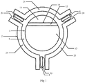
- FIG. 1 is a structural schematic drawing of the angular position sensor provided in Embodiment 1 of the present invention.
- this angle position sensor includes a rotor core 1 as well as a stator core 2 coaxially around this rotor core 1, and between the rotor core 1 and the stator core 2 is a first air gap 3.
- the inside of the rotor core 1 is provided with a second air gap 10, which is used for receiving a hard magnet 12, such that this hard magnet 12 can constitute a magnetic circuit together with the rotor core 1 and the stator core 2.
- a third air gap 20 where a magnetic flux sensing element 4 is located for measuring the magnetic flux and converting it into an electrical signal.
- the hard magnet 12 constitutes a magnetic circuit together with the rotor core 1 and the stator core 2, thus making the exterior magnetic field distribution of the rotor core 1 close to that of the magnetic circuit constituted by the ring magnet. It is discovered by further research that the size of the first air gap 3 relative to the rotor core 1 will affect the magnetic field distribution, i.e. affecting the linearity range and the linearity of the angular position sensor, which will be explained below in detail with reference to Figure 2 .
- Figure 2 is a section-enlarged schematic drawing of the rotor core 1 and the first air gap 3 in Figure 1 .
- the first air gap 3 is a uniformly distributed ring air gap, and its size in any radial direction of the rotor core 1 is called the width H of the first air gap, which usually determines the size of the first air gap 3 (taking no account of thickness of the rotor core 1); besides, in the drawing is also shown a certain diameter D of the rotor core, which usually determines the size of the rotor core 1 (taking no account of thickness of the rotor core 1).
- FIG. 3 shows the magnetic field distribution drawing of the angular position sensor in the above embodiment. It can be seen from the drawing that with the above setting, the line of magnetic force is distributed uniformly through the third air gap 20 (i.e. the position where the magnetic flux sensing element 4 (see Figure 1 ) is located) (as shown inside the dotted circle). Besides, when the rotor core 1 rotates with the measured object, the stator core 1 rotates relative to the stator core 2, and the hard magnet 12 also rotates together with the rotor core 1. Therefore, the magnetic flux through the magnetic flux sensing element 4 is increased or decreased accordingly, and the variation of the magnetic flux is basically linear with the rotation angle of the rotor core 1 relative to the stator core 2 within a certain range of the rotation angle.
- the rotor core 1 and the stator core 2 are usually made up of multiple pieces of soft magnetic material for the formation of an air gap between them.
- the rotor core 1 is made up of two pieces of soft magnetic material, such a design being simpler. Certainly, three or more pieces can also be used, so long as their exterior magnetic field distribution can meet the requirement. Please see Figure 1 for details.
- the rotor core 1 is composed of two rotor portions 11 and 13, between which is a second air gap 10 filled with the hard magnet 12.
- the stator core 2 in this embodiment uses three pieces of soft magnetic material (i.e. being composed of three stator portions 21, 23 and 25), and thus the third air gap 20 where the magnetic flux sensing element 4 is fixed is formed between two adjacent stator portions.
- the number of the stator portion is unlimited to that mentioned above. It can be two or more than three and thus two or more magnetic flux sensing elements 4 can be provided correspondingly, it is optional with no effect on the substance of the present invention.
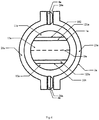
- FIG. 4 is a structural schematic drawing of the angular position sensor provided in Embodiment 2 of the present invention.
- its rotor core 1 a is composed of three rotor portions 11 a, 13a and 15a, and thus the second air gap is formed between two adjacent rotor portions.
- the second air gap as shown in the drawing includes a first portion 102 and a second portion 104, which are in parallel with the diameter Da, located at both sides of the diameter Da, and provided inside with hard magnetic bodies 121 a and 123a.
- the magnetic poles of the hard magnetic bodies 121a and 123a are set in the same direction (for example, if the N poles of the hard magnetic bodies 121a and 123a are both inwardly perpendicular to the principal plane, then the S poles are both outwardly perpendicular to the principal plane; or vice versa), such that the hard magnetic bodies 121a and 123a can constitute a magnetic circuit together with the rotor core 1 a and the stator core 2a.
- the stator core 2a is composed of two stator portions 21 a and 23, and thus the third air gap 20a is formed between them, as shown in the drawing.
- the two magnetic flux sensing elements 4a are placed in the third air gap 20a.
- FIG. 5 is a structural schematic drawing of the angular position sensor provided in Embodiment 3 of the present invention.
- the structure of its stator core 2b is the same with that in Embodiment 2, and will no longer be described here in detail.
- its rotor core 1 b is composed of two symmetrical rotor portions 11 b and 13b, that is, the second air gap 10b is located where the diameter Db is.
- the second air gap 10b is provided in the middle with one hard magnetic body 12b, which is used for constituting a magnetic circuit together with the rotor core 1 b and the stator core 2b.
- FIG. 6 is a structural schematic drawing of the angular position sensor provided in Embodiment 4 of the present invention.
- the structure of the rotor core 1c and the stator core 2c is basically the same with that in Embodiment 3, with the difference only in how the hard magnet is set inside the second air gap 10c. That is, the second air gap 10c is provided inside with two hard magnetic bodies 12c, which are symmetrically positioned relative to the axis of the rotor core 1 c, with their magnetic poles set in the same direction, such that the two hard magnetic bodies 12c can constitute a magnetic circuit together with the rotor core 1 c and the stator core 2c.
- the second air gap is designed to be linear along a certain diameter direction of the rotor core.
- the second air gaps in Embodiments 1 and 2 are in parallel with a certain diameter of the rotor core; and the second air gaps in Embodiments 3 and 4 are located where a certain diameter of the rotor core is.
- the size of the hard magnet has a certain influence on the linearity of the angular position sensor, i.e. the more slender the hard magnet is, the better the linearity of the angular position sensor will be.
- the size of the hard magnet can be set according to the size of the second air gap.
- the size of the second air gap in the above-mentioned diameter direction is called its length, and the size of the second air gap in the radial direction of the rotor core its width.
- the second air gap 10 is in parallel with the diameter D of the rotor core and located at a side of the diameter D, with its size in this diameter direction X being called its length L and its size in the radial direction Y of the rotor core its width S.
- the ratio of the length L to the width S of the second air gap 10 is bigger than or equal to 5:1, which in this section means the ratio of length to width of the hard magnet 12 is bigger than or equal to 5:1, the requirement of the linearity of the angular position sensor can then be met.
- the bigger the ratio of length to width of the hard magnetic material is, the better the linearity of the angular position sensor will be.
- the ratio as required is acceptable, such as 12:1.
- the ratio of the width H of the first air gap 3 to the width S of the second air gap 10 also has a certain influence on the linearity of the angular position sensor, that is, the bigger the width ratio is, the better the linearity of the angular position sensor will be.
- the width H of the first air gap 3 is already small enough, usually a few millimetres (e.g. 4 mm). Therefore, in consideration of the processing difficulty, the ratio could not be infinitely big. It is discovered by research that the requirement can be met when the ratio is equal to 2:1. Therefore, the ratio of the width H of the first air gap 3 to the width S of the second air gap 10 is bigger than or equal to 2:1.
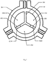
- FIG. 7 is a structural schematic drawing of the angular position sensor provided in Embodiment 5 of the present invention.
- the structure of the stator core 2 in this embodiment is the same with that in Embodiment 1, and will no longer be described here in detail. They are different in the structure of the rotor core 1 d.
- the rotor core 1 d is composed of three rotor portions 11 d, 13d and 15d, between which forms a second air gap.
- this second air gap includes three portions 101, 103 and 105 uniformly distributed in three radial directions of the rotor core 1 d, wherein the two portions 103 and 105 therein are provided inside with a first hard magnet 121d and a second hard magnet 122d, respectively, to constitute a magnetic circuit together with the rotor core 1 d and the stator core 2d.
- the magnetic poles of the first hard magnet 121 d and the second hard magnet 122d are set in the opposite direction, so as to prevent the line of magnetic force from being closed inside the rotor core 1 d.
- the second air gap 10e is different from those in the above embodiments mainly in shape that it is a shuttle-shaped air gap located at a certain diameter of the rotor core 1 e. It is filled with a hard magnet 12e, so as to constitute a magnetic circuit together with the rotor core 1 e and the stator core 2e. It is further explained in this embodiment that the reasonable setting of the ratio of the width H of the first air gap to the diameter D of the rotor core allows for more flexible design of the rotor core. That is, with the shape of the second air gap slightly changed, the line of magnetic force where the magnetic flux sensing element is located can still be distributed relatively uniformly, making the angular position sensor obtain good linearity within a wider range.
- FIG 9 is a schematic drawing of the relation between the magnetic induction intensity and the rotation angle obtained according to one embodiment of the present invention. As shown in the drawing, the magnetic induction intensity B obtains the better linearity when the rotation angle A is between 60o and 300o, and it comes to the complete linearity range bigger than 180o.
- the angular position sensor according to the present invention includes a rotor core as well as a stator core coaxially around this rotor core, wherein a first air gap is provided between the rotor core and the stator core, a second air gap with a hard magnet therein is provided inside the rotor core, and a third air gap with a magnetic flux sensing element therein is provided inside the stator core.
Landscapes
- Physics & Mathematics (AREA)
- General Physics & Mathematics (AREA)
- Transmission And Conversion Of Sensor Element Output (AREA)
- Measurement Of Length, Angles, Or The Like Using Electric Or Magnetic Means (AREA)
Description
- The present invention relates to a sensor device, and particularly to an angular position sensor device with a wide linearity range and good linearity.
- An angular position sensor, as an important sensor device, is widely used in the automobile and other electromechanical control fields. How to broaden its linearity range and improve its linearity has always been a subject those skilled in the art are dedicated to. A commonly used angular position sensor uses a magnetic induction element to detect the magnetic field variation, which is then converted into the electrical signal output corresponding to the angular position. In order to improve its output linearity relative to the rotation angle of the measured object and broaden the linearity range, those skilled in the art have done a great deal of research, and obtained various design proposals about the magnetic circuit.
- For example, the American patent specification
US-5861745A disclosed on January 19, 1999 presents an angle measurement device, which obtains the complete linearity range bigger than 180º by making use of a radially magnetized ring magnet that rotates together with the measured object. In this solution, however, the wider the required linearity range is, the bigger the ring magnet will be, thus increasing the cost of raw material; besides, the magnet material is more difficult to be processed than other metal materials, especially the more complicated ring magnet that is adopted in this solution, whose accuracy is difficult to be guaranteed during processing and positioning, which will increase the processing cost in the production process. -
US 6,414,482 discloses a sensor core used in a non-contact type rotational angle sensor constructed of an outer core made of a magnetic material, an inner core made of a magnetic material in a disc shape disposed coaxially with and inside the outer core, a first air gap produced between an inner peripheral surface of the outer core and an outer peripheral plane of the inner core, a second air gap produced extending in a radial direction of the outer core to the first air gap, and a plate-like magnet magnetized in its thickness direction and mounted in a mounting gap of the inner core. The inner peripheral surface of the outer core is provided with stepped portions so that the first air gap stepwise increases in dimension with approach toward the second air gap. - The invention is defined in the attached independent claim to which reference should now be made. Further, optional features may be found in the sub-claims appended thereto.
- A purpose of the present invention is to provide an angular position sensor, which is not only good in the linearity, but simpler in the manufacturing process and lower in the production cost as well.
- In order to achieve the above purpose, the present invention provides an angular position sensor including a rotor core as well as a stator core coaxially around this rotor core. A first air gap is provided between the rotor core and the stator core. The first air gap is a uniformly distributed ring air gap, with its size in the radial direction of the rotor core being called the width of the first air gap. The ratio of the width of the first air gap to the diameter of the rotor core is bigger than or equal to 1:5. A second air gap with a hard magnet therein is provided inside the rotor core, and a third air gap with a magnetic flux sensing element therein is provided inside the stator core.
- Furthermore, the second air gap may be designed to be linear along a certain diameter direction of the rotor core, with the size of the second air gap in this diameter direction being called its length and the size of the second air gap in the radial direction of the rotor core its width.
- Furthermore, the ratio of the length to the width of the second air gap may be bigger than or equal to 5:1.
- Furthermore, the second air gap may be filled with the hard magnet.
- Furthermore, the ratio of the width of the first air gap to that of the second air gap may be bigger than or equal to 2:1.
- Furthermore, the second air gap may be in parallel with the above-mentioned diameter and located at a side of the diameter.
- Furthermore, the second air gap may include a first portion and a second portion, which are in parallel with the above-mentioned diameter and located at both sides of this diameter.
- Furthermore, the first portion and the second portion may be provided inside with a hard magnet, respectively, whose magnetic poles are set in the same direction.
- Furthermore, the second air gap may be located where the above-mentioned diameter is.
- Furthermore, the second air gap may be provided inside with two hard magnets symmetrical to the axis of the rotor core, with the magnetic poles of the two hard magnets set in the same direction.
- Furthermore, the second air gap may be provided in the middle with one hard magnet.
- Furthermore, the second air gap may include three portions uniformly distributed in three radial directions of the rotor core, with the two portions therein being provided with a first hard magnet and a second hard magnet, respectively.
- Furthermore, the magnetic poles of the first and the second hard magnets may be set in the opposite direction.
- Furthermore, the second air gap, located at a certain diameter of the rotor core, may be of a shuttle-shaped design.
- Furthermore, the rotor core may include multiple rotor portions, with the above-mentioned second air gap formed between two adjacent rotor portions.
- Furthermore, the stator core may include multiple stator portions, with the above-mentioned third air gap formed between two adjacent stator portions.
- Furthermore, the rotor core and the stator core may be made from soft magnetic material.
- In summary, the present invention, by substituting the combination of the hard magnet and the rotor core for the prior art ring magnet, obtains good linearity within a wider range. Compared with the prior art, the present invention is easy in assembly, as well as lower in cost and simplified in process due to no need for processing the more difficult ring magnet. Moreover, by changing the size of the air gap and the hard magnet, the present invention can make the magnetic flux density where the magnetic flux sensing element is located be linear with the rotation angle within a wider range, thus obtaining a wider linearity range and better linearity as well as improving flexibility of the structure of the rotor core and the stator core.
-
-
Figure 1 is a structural schematic drawing of the angular position sensor provided inEmbodiment 1 of the present invention. -
Figure 2 is a section-enlarged schematic drawing of therotor core 1 and thefirst air gap 3 inFigure 1 . -
Figure 3 is a magnetic field distribution drawing of the angular position sensor provided inEmbodiment 1 of the present invention. -
Figure 4 is a structural schematic drawing of the angular position sensor provided inEmbodiment 2 of the present invention. -
Figure 5 is a structural schematic drawing of the angular position sensor provided inEmbodiment 3 of the present invention. -
Figure 6 is a structural schematic drawing of the angular position sensor provided inEmbodiment 4 of the present invention. -
Figure 7 is a structural schematic drawing of the angular position sensor provided in Embodiment 5 of the present invention. -
Figure 8 is a structural schematic drawing of the angular position sensor provided in Embodiment 6 of the present invention. -
Figure 9 is a schematic drawing of the relation between the magnetic induction intensity and the rotation angle obtained according to one embodiment of the present invention. - In order to make purposes and characteristics of the present invention more obvious and more understandable, the embodiments of the present invention will further be described below with reference to drawings.
- Reference is made to
Figure 1 which is a structural schematic drawing of the angular position sensor provided inEmbodiment 1 of the present invention. As shown in the drawing, this angle position sensor includes arotor core 1 as well as astator core 2 coaxially around thisrotor core 1, and between therotor core 1 and thestator core 2 is afirst air gap 3. The inside of therotor core 1 is provided with asecond air gap 10, which is used for receiving ahard magnet 12, such that thishard magnet 12 can constitute a magnetic circuit together with therotor core 1 and thestator core 2. Also, inside thestator core 2 is athird air gap 20, where a magneticflux sensing element 4 is located for measuring the magnetic flux and converting it into an electrical signal. - With this magnetic circuit design, the
hard magnet 12 constitutes a magnetic circuit together with therotor core 1 and thestator core 2, thus making the exterior magnetic field distribution of therotor core 1 close to that of the magnetic circuit constituted by the ring magnet. It is discovered by further research that the size of thefirst air gap 3 relative to therotor core 1 will affect the magnetic field distribution, i.e. affecting the linearity range and the linearity of the angular position sensor, which will be explained below in detail with reference toFigure 2 . - Reference is made to
Figure 2 which is a section-enlarged schematic drawing of therotor core 1 and thefirst air gap 3 inFigure 1 . As shown in the drawing, thefirst air gap 3 is a uniformly distributed ring air gap, and its size in any radial direction of therotor core 1 is called the width H of the first air gap, which usually determines the size of the first air gap 3 (taking no account of thickness of the rotor core 1); besides, in the drawing is also shown a certain diameter D of the rotor core, which usually determines the size of the rotor core 1 (taking no account of thickness of the rotor core 1). It is discovered by research that when the ratio of the width H of the first air gap to the diameter D of the rotor core is bigger than or equal to 1:5, the exterior magnetic field distribution of therotor core 1 can already meet the requirement, i.e. obtaining the good linearity within a wider range. It is discovered by the further research that with the above ratio increasing, the linearity of the angular position sensor will become better, while the magnetic field intensity weaker. Therefore, in practice those skilled in the art can set the ratio as required, which is usually smaller than 1:1. - Reference is made to
Figure 3 which shows the magnetic field distribution drawing of the angular position sensor in the above embodiment. It can be seen from the drawing that with the above setting, the line of magnetic force is distributed uniformly through the third air gap 20 (i.e. the position where the magnetic flux sensing element 4 (seeFigure 1 ) is located) (as shown inside the dotted circle). Besides, when therotor core 1 rotates with the measured object, thestator core 1 rotates relative to thestator core 2, and thehard magnet 12 also rotates together with therotor core 1. Therefore, the magnetic flux through the magneticflux sensing element 4 is increased or decreased accordingly, and the variation of the magnetic flux is basically linear with the rotation angle of therotor core 1 relative to thestator core 2 within a certain range of the rotation angle. - The
rotor core 1 and thestator core 2 are usually made up of multiple pieces of soft magnetic material for the formation of an air gap between them. In this embodiment, for example, therotor core 1 is made up of two pieces of soft magnetic material, such a design being simpler. Certainly, three or more pieces can also be used, so long as their exterior magnetic field distribution can meet the requirement. Please seeFigure 1 for details. Therotor core 1 is composed of tworotor portions second air gap 10 filled with thehard magnet 12. Thestator core 2 in this embodiment uses three pieces of soft magnetic material (i.e. being composed of threestator portions third air gap 20 where the magneticflux sensing element 4 is fixed is formed between two adjacent stator portions. Likewise, the number of the stator portion is unlimited to that mentioned above. It can be two or more than three and thus two or more magneticflux sensing elements 4 can be provided correspondingly, it is optional with no effect on the substance of the present invention. - In addition, it has been explained in the above description that, with the ratio of the width H of the first air gap to the diameter D of the rotor core reasonably set, the line of magnetic force where the magnetic
flux sensing element 4 is located is distributed uniformly, making the angular position sensor obtain good linearity within a wider range, thus improving flexibility of the structure of therotor core 1 and thestator core 2. It will be specifically described in the following embodiments. - Reference is made to
Figure 4 which is a structural schematic drawing of the angular position sensor provided inEmbodiment 2 of the present invention. As shown in the drawing, its rotor core 1 a is composed of threerotor portions first portion 102 and asecond portion 104, which are in parallel with the diameter Da, located at both sides of the diameter Da, and provided inside with hardmagnetic bodies magnetic bodies magnetic bodies magnetic bodies stator core 2a. In addition, thestator core 2a is composed of twostator portions third air gap 20a is formed between them, as shown in the drawing. Correspondingly, the two magneticflux sensing elements 4a are placed in thethird air gap 20a. -
Figure 5 is a structural schematic drawing of the angular position sensor provided inEmbodiment 3 of the present invention. As shown in the drawing, the structure of itsstator core 2b is the same with that inEmbodiment 2, and will no longer be described here in detail. However, its rotor core 1 b is composed of twosymmetrical rotor portions second air gap 10b is located where the diameter Db is. In addition, thesecond air gap 10b is provided in the middle with one hardmagnetic body 12b, which is used for constituting a magnetic circuit together with the rotor core 1 b and thestator core 2b. -
Figure 6 is a structural schematic drawing of the angular position sensor provided inEmbodiment 4 of the present invention. As shown in the drawing, the structure of therotor core 1c and thestator core 2c is basically the same with that inEmbodiment 3, with the difference only in how the hard magnet is set inside thesecond air gap 10c. That is, thesecond air gap 10c is provided inside with two hardmagnetic bodies 12c, which are symmetrically positioned relative to the axis of therotor core 1 c, with their magnetic poles set in the same direction, such that the two hardmagnetic bodies 12c can constitute a magnetic circuit together with therotor core 1 c and thestator core 2c. - In the above four embodiments, the second air gap is designed to be linear along a certain diameter direction of the rotor core. For example, the second air gaps in
Embodiments Embodiments Embodiment 1 as an example for convenience, and please seeFigure 2 for details. Thesecond air gap 10 is in parallel with the diameter D of the rotor core and located at a side of the diameter D, with its size in this diameter direction X being called its length L and its size in the radial direction Y of the rotor core its width S. It is discovered by research that when the ratio of the length L to the width S of thesecond air gap 10 is bigger than or equal to 5:1, which in this section means the ratio of length to width of thehard magnet 12 is bigger than or equal to 5:1, the requirement of the linearity of the angular position sensor can then be met. In addition, the bigger the ratio of length to width of the hard magnetic material is, the better the linearity of the angular position sensor will be. However, due to restriction of the practical production process, the ratio as required is acceptable, such as 12:1. - It is discovered by the further research that the ratio of the width H of the
first air gap 3 to the width S of thesecond air gap 10 also has a certain influence on the linearity of the angular position sensor, that is, the bigger the width ratio is, the better the linearity of the angular position sensor will be. In practice, however, the width H of thefirst air gap 3 is already small enough, usually a few millimetres (e.g. 4 mm). Therefore, in consideration of the processing difficulty, the ratio could not be infinitely big. It is discovered by research that the requirement can be met when the ratio is equal to 2:1. Therefore, the ratio of the width H of thefirst air gap 3 to the width S of thesecond air gap 10 is bigger than or equal to 2:1. - Reference is made to
Figure 7 which is a structural schematic drawing of the angular position sensor provided in Embodiment 5 of the present invention. The structure of thestator core 2 in this embodiment is the same with that inEmbodiment 1, and will no longer be described here in detail. They are different in the structure of therotor core 1 d. Therotor core 1 d is composed of threerotor portions portions rotor core 1 d, wherein the twoportions hard magnet 121d and a secondhard magnet 122d, respectively, to constitute a magnetic circuit together with therotor core 1 d and thestator core 2d. In addition, the magnetic poles of the firsthard magnet 121 d and the secondhard magnet 122d are set in the opposite direction, so as to prevent the line of magnetic force from being closed inside therotor core 1 d. - Reference is made to
Figure 8 which is a structural schematic drawing of the angular position sensor provided in Embodiment 6 of the present invention. In this embodiment, thesecond air gap 10e is different from those in the above embodiments mainly in shape that it is a shuttle-shaped air gap located at a certain diameter of the rotor core 1 e. It is filled with ahard magnet 12e, so as to constitute a magnetic circuit together with the rotor core 1 e and thestator core 2e. It is further explained in this embodiment that the reasonable setting of the ratio of the width H of the first air gap to the diameter D of the rotor core allows for more flexible design of the rotor core. That is, with the shape of the second air gap slightly changed, the line of magnetic force where the magnetic flux sensing element is located can still be distributed relatively uniformly, making the angular position sensor obtain good linearity within a wider range. - It can be seen from the embodiments of the present invention that, by substituting a certain combination of the hard magnetic material and the soft magnetic material for the prior art ring magnet, one can obtain the exterior magnetic field effect that is close to what the ring magnet produces and can further be improved by the change of the size of the air gap and the hard magnetic material, such that the magnetic flux density where the magnetic flux sensing element is located is directly proportional to the rotation angle of the rotor core relative to the stator core within a wider range for better linearity.
-
Figure 9 is a schematic drawing of the relation between the magnetic induction intensity and the rotation angle obtained according to one embodiment of the present invention. As shown in the drawing, the magnetic induction intensity B obtains the better linearity when the rotation angle A is between 60º and 300º, and it comes to the complete linearity range bigger than 180º. - What is mentioned above is only for illustration, and will not limit the present invention. The extent of protection of the present invention should be determined by the terms of the claims.
- The angular position sensor according to the present invention includes a rotor core as well as a stator core coaxially around this rotor core, wherein a first air gap is provided between the rotor core and the stator core, a second air gap with a hard magnet therein is provided inside the rotor core, and a third air gap with a magnetic flux sensing element therein is provided inside the stator core. It is obvious that the present invention, by substituting the combination of the hard magnet and the rotor core for the design of ring magnet in the prior art, obtains the good linearity within a wider range. Compared with the prior art, the present invention is easy in assembly, as well as lower in cost and simplified in process due to no need for processing the more difficult ring magnet. Thus, it possesses practical applicability in Industry.
Claims (13)
- An angular position sensor, comprising a rotor core (1, 1 a, 1 b, 1 c, 1 d) and a stator core (2, 2a, 2b, 2c, 2d) coaxially around the rotor core, wherein:a first air gap (3) is provided between the rotor core and the stator core, which is a uniformly distributed ring air gap, with its size in the radial direction of the rotor core being called width of the first air gap, and the ratio of its width to the diameter of the rotor core being bigger than or equal to 1:5;a second air gap (10) with a hard magnet (12) therein is provided inside the rotor core; anda third air gap (20) with a magnetic flux sensing element (4) therein is provided inside the stator core;characterized in that the ratio of the length to the width of the second air gap is bigger than or equal to 5:1 and in that the ratio of the width of the first air gap (3) to that of the second air gap (10) is bigger than or equal to 2:1.
- The angular position sensor according to claim 1, characterized in that the second air gap (10) is designed to be linear along a certain diameter direction of the rotor core, with the size of the second air gap in this diameter direction being called its length and the size of the second air gap in the radial direction of the rotor core its width.
- The angular position sensor according to claim 1, characterized in that the second air gap (10) is filled with the hard magnet (12).
- The angular position sensor according to claim 2, characterized in that the second air gap (10) is in parallel with the above-mentioned diameter and located at one side of the diameter.
- The angular position sensor according to claim 2, characterized in that the second air gap (10) includes a first portion (102) and a second portion (104), which are in parallel with the above-mentioned diameter and located at both sides of this diameter; the inside of the above-mentioned first portion and second portion may be provided with a hard magnet, respectively, whose magnetic poles are set in the same direction.
- The angular position sensor according to claim 2, characterized in that the second air gap (10) is located where the above-mentioned diameter is.
- The angular position sensor according to claim 6, characterized in that the second air gap (10) is provided inside with two hard magnets symmetrical to the axis of the rotor core, magnetic poles of the two hard magnets being set in the same direction.
- The angular position sensor according to claim 6, characterized in that the second air gap (10) is provided in the middle with one hard magnet.
- The angular position sensor according to claim 1, characterized in that the second air gap (10) includes three portions (101, 103, 105) uniformly distributed in three radial directions of the rotor core, with two portions therein being provided with a first hard magnet and a second hard magnet (121d, 122d), respectively;
the magnetic poles of the first and the second hard magnets may be set in the opposite direction. - The angular position sensor according to claim 1, characterized in that the second air gap (10), located at a certain diameter of the rotor core, is of a shuttle-shaped design.
- The angular position sensor according to claim 1, characterized in that the rotor core includes multiple rotor portions (11, 13), with the above-mentioned second air gap formed between two adjacent rotor portions.
- The angular position sensor according to claim 1, characterized in that the stator core includes multiple stator portions (21, 23, 25), with the above-mentioned third air gap formed between two adjacent stator portions.
- The angular position sensor according to claim 1, characterized in that the rotor core and the stator core are made from soft magnetic material.
Applications Claiming Priority (2)
| Application Number | Priority Date | Filing Date | Title |
|---|---|---|---|
| CN 200810200016 CN101358833B (en) | 2008-09-17 | 2008-09-17 | Angle and position sensor |
| PCT/CN2009/001029 WO2010031246A1 (en) | 2008-09-17 | 2009-09-15 | An angle position sensor |
Publications (3)
| Publication Number | Publication Date |
|---|---|
| EP2330379A1 EP2330379A1 (en) | 2011-06-08 |
| EP2330379A4 EP2330379A4 (en) | 2014-11-19 |
| EP2330379B1 true EP2330379B1 (en) | 2017-04-05 |
Family
ID=40331350
Family Applications (1)
| Application Number | Title | Priority Date | Filing Date |
|---|---|---|---|
| EP09813967.8A Not-in-force EP2330379B1 (en) | 2008-09-17 | 2009-09-15 | An angle position sensor |
Country Status (4)
| Country | Link |
|---|---|
| US (1) | US8766627B2 (en) |
| EP (1) | EP2330379B1 (en) |
| CN (1) | CN101358833B (en) |
| WO (1) | WO2010031246A1 (en) |
Families Citing this family (4)
| Publication number | Priority date | Publication date | Assignee | Title |
|---|---|---|---|---|
| CN101358833B (en) * | 2008-09-17 | 2011-01-12 | 联合汽车电子有限公司 | Angle and position sensor |
| CN102564253A (en) * | 2010-12-17 | 2012-07-11 | 联创汽车电子有限公司 | Hall angle/position sensor |
| JP2018182161A (en) * | 2017-04-18 | 2018-11-15 | Tdk株式会社 | Magnet, magnet structure, and rotation angle detector |
| CN120928565B (en) * | 2025-10-13 | 2025-12-12 | 上海卫星互联网研究院有限公司 | A magnetic circuit module, a microelectromechanical system rotating mirror, and a laser communication terminal |
Family Cites Families (14)
| Publication number | Priority date | Publication date | Assignee | Title |
|---|---|---|---|---|
| US4568846A (en) * | 1983-10-28 | 1986-02-04 | Welco Industries | Permanent magnet laminated rotor with conductor bars |
| FR2670286B1 (en) * | 1990-12-05 | 1993-03-26 | Moving Magnet Tech | MAGNETIC POSITION AND SPEED SENSOR WITH HALL PROBE. |
| US5789917A (en) * | 1990-12-05 | 1998-08-04 | Moving Magnet Technologie Sa | Magnetic position sensor with hall probe formed in an air gap of a stator |
| US6259180B1 (en) * | 1996-07-02 | 2001-07-10 | Schlenker Enterprises, Ltd. | Motor including embedded permanent magnet rotor and method for making the same |
| DE19630764A1 (en) | 1995-09-29 | 1997-04-03 | Bosch Gmbh Robert | Contact free identification device for relative movement |
| DE19634281C2 (en) * | 1996-08-24 | 2000-01-27 | Bosch Gmbh Robert | Measuring device for contactless detection of an angle of rotation or a linear movement |
| US6141482A (en) | 1997-11-13 | 2000-10-31 | Foto Fantasy, Inc. | Method for saving, accessing and reprinting a digitized photographic image |
| JP3491596B2 (en) * | 1999-06-28 | 2004-01-26 | 株式会社デンソー | Rotation angle detector |
| US6414482B1 (en) * | 1999-11-11 | 2002-07-02 | Aisan Kogyo Kabushiki Kaisha | Non-contact type rotational angle sensor and sensor core used in the sensor |
| JP3596667B2 (en) * | 2000-01-26 | 2004-12-02 | 株式会社デンソー | Rotation angle detector |
| ITTO20010182A1 (en) * | 2001-03-02 | 2002-09-02 | Fiat Ricerche | SYNCHRONOUS TYPE ELECTRIC MACHINE. |
| US6693424B2 (en) | 2001-06-08 | 2004-02-17 | Denso Corporation | Magnetic rotation angle sensor |
| CN201281584Y (en) * | 2008-09-17 | 2009-07-29 | 联合汽车电子有限公司 | Angle and position sensor |
| CN101358833B (en) * | 2008-09-17 | 2011-01-12 | 联合汽车电子有限公司 | Angle and position sensor |
-
2008
- 2008-09-17 CN CN 200810200016 patent/CN101358833B/en active Active
-
2009
- 2009-09-15 WO PCT/CN2009/001029 patent/WO2010031246A1/en not_active Ceased
- 2009-09-15 EP EP09813967.8A patent/EP2330379B1/en not_active Not-in-force
- 2009-09-15 US US13/119,482 patent/US8766627B2/en active Active
Also Published As
| Publication number | Publication date |
|---|---|
| US20110234211A1 (en) | 2011-09-29 |
| CN101358833B (en) | 2011-01-12 |
| US8766627B2 (en) | 2014-07-01 |
| WO2010031246A1 (en) | 2010-03-25 |
| CN101358833A (en) | 2009-02-04 |
| EP2330379A4 (en) | 2014-11-19 |
| EP2330379A1 (en) | 2011-06-08 |
Similar Documents
| Publication | Publication Date | Title |
|---|---|---|
| EP2988100B1 (en) | Electronic water meter | |
| KR101426877B1 (en) | Rotation angle detection device, rotary machine, and rotation angle detection method | |
| US7021160B2 (en) | Apparatus for sensing position and/or torque | |
| CN102066879B (en) | Magnetic encoder and actuator | |
| DE112004002011B4 (en) | Magnetic encoder and actuator | |
| CN102822632A (en) | Position sensor | |
| CN103154687A (en) | Device comprising a torque sensor and a rotation angle sensor | |
| US20190086236A1 (en) | Magnetic sensor device and method for determining a rotation speed, a direction of rotation, and/or a rotation angle of a magnetic component about a rotation axis | |
| US8766627B2 (en) | Angle position sensor | |
| US20090146651A1 (en) | Rotation angle sensor | |
| CN115979409B (en) | Angular Vibration Sensor and Angular Vibration Detection Method Based on Magnetohydrodynamics | |
| JPH04331302A (en) | Measuring apparatus for measuring angle of rotation | |
| JP5666324B2 (en) | Current sensor | |
| JP5898864B2 (en) | motor | |
| JPH03179216A (en) | Magnetic rotation sensor and manufacture thereof | |
| JP2009271054A (en) | Position detecting device and rotary linear motion motor with the same | |
| US20040250632A1 (en) | Apparatus for sensing position and/or torque | |
| CN201281584Y (en) | Angle and position sensor | |
| JP5249174B2 (en) | Rotation angle sensor | |
| JP2011513757A (en) | Angle measurement system | |
| JP4382927B2 (en) | Relative rotation angle detector | |
| JPH0674838A (en) | Strain detecting device, shield for strain detecting device, and passive shaft | |
| RU72319U1 (en) | MAGNET CORNER CONVERTER | |
| JPH09127142A (en) | Sensor ring | |
| JP2002343638A (en) | Magnet material for encoder |
Legal Events
| Date | Code | Title | Description |
|---|---|---|---|
| PUAI | Public reference made under article 153(3) epc to a published international application that has entered the european phase |
Free format text: ORIGINAL CODE: 0009012 |
|
| 17P | Request for examination filed |
Effective date: 20110411 |
|
| AK | Designated contracting states |
Kind code of ref document: A1 Designated state(s): AT BE BG CH CY CZ DE DK EE ES FI FR GB GR HR HU IE IS IT LI LT LU LV MC MK MT NL NO PL PT RO SE SI SK SM TR |
|
| AX | Request for extension of the european patent |
Extension state: AL BA RS |
|
| DAX | Request for extension of the european patent (deleted) | ||
| A4 | Supplementary search report drawn up and despatched |
Effective date: 20141020 |
|
| RIC1 | Information provided on ipc code assigned before grant |
Ipc: G01B 7/30 20060101AFI20141014BHEP Ipc: G01D 5/12 20060101ALI20141014BHEP Ipc: G01D 5/14 20060101ALI20141014BHEP |
|
| 17Q | First examination report despatched |
Effective date: 20150703 |
|
| REG | Reference to a national code |
Ref country code: DE Ref legal event code: R079 Ref document number: 602009045283 Country of ref document: DE Free format text: PREVIOUS MAIN CLASS: G01B0007300000 Ipc: G01D0005140000 |
|
| RIC1 | Information provided on ipc code assigned before grant |
Ipc: G01D 5/14 20060101AFI20160425BHEP |
|
| GRAP | Despatch of communication of intention to grant a patent |
Free format text: ORIGINAL CODE: EPIDOSNIGR1 |
|
| INTG | Intention to grant announced |
Effective date: 20160622 |
|
| RIN1 | Information on inventor provided before grant (corrected) |
Inventor name: SCHOEPKE, MANUEL Inventor name: CHEN, YAN Inventor name: WANG, CHUNJIAN Inventor name: DENG, YU Inventor name: ZHANG, SHUN |
|
| GRAJ | Information related to disapproval of communication of intention to grant by the applicant or resumption of examination proceedings by the epo deleted |
Free format text: ORIGINAL CODE: EPIDOSDIGR1 |
|
| GRAP | Despatch of communication of intention to grant a patent |
Free format text: ORIGINAL CODE: EPIDOSNIGR1 |
|
| INTC | Intention to grant announced (deleted) | ||
| INTG | Intention to grant announced |
Effective date: 20161103 |
|
| GRAS | Grant fee paid |
Free format text: ORIGINAL CODE: EPIDOSNIGR3 |
|
| GRAA | (expected) grant |
Free format text: ORIGINAL CODE: 0009210 |
|
| AK | Designated contracting states |
Kind code of ref document: B1 Designated state(s): AT BE BG CH CY CZ DE DK EE ES FI FR GB GR HR HU IE IS IT LI LT LU LV MC MK MT NL NO PL PT RO SE SI SK SM TR |
|
| REG | Reference to a national code |
Ref country code: GB Ref legal event code: FG4D |
|
| REG | Reference to a national code |
Ref country code: CH Ref legal event code: EP |
|
| REG | Reference to a national code |
Ref country code: AT Ref legal event code: REF Ref document number: 882253 Country of ref document: AT Kind code of ref document: T Effective date: 20170415 |
|
| REG | Reference to a national code |
Ref country code: IE Ref legal event code: FG4D |
|
| REG | Reference to a national code |
Ref country code: DE Ref legal event code: R096 Ref document number: 602009045283 Country of ref document: DE |
|
| REG | Reference to a national code |
Ref country code: NL Ref legal event code: MP Effective date: 20170405 |
|
| REG | Reference to a national code |
Ref country code: LT Ref legal event code: MG4D |
|
| REG | Reference to a national code |
Ref country code: AT Ref legal event code: MK05 Ref document number: 882253 Country of ref document: AT Kind code of ref document: T Effective date: 20170405 |
|
| PG25 | Lapsed in a contracting state [announced via postgrant information from national office to epo] |
Ref country code: NL Free format text: LAPSE BECAUSE OF FAILURE TO SUBMIT A TRANSLATION OF THE DESCRIPTION OR TO PAY THE FEE WITHIN THE PRESCRIBED TIME-LIMIT Effective date: 20170405 |
|
| PG25 | Lapsed in a contracting state [announced via postgrant information from national office to epo] |
Ref country code: FI Free format text: LAPSE BECAUSE OF FAILURE TO SUBMIT A TRANSLATION OF THE DESCRIPTION OR TO PAY THE FEE WITHIN THE PRESCRIBED TIME-LIMIT Effective date: 20170405 Ref country code: AT Free format text: LAPSE BECAUSE OF FAILURE TO SUBMIT A TRANSLATION OF THE DESCRIPTION OR TO PAY THE FEE WITHIN THE PRESCRIBED TIME-LIMIT Effective date: 20170405 Ref country code: NO Free format text: LAPSE BECAUSE OF FAILURE TO SUBMIT A TRANSLATION OF THE DESCRIPTION OR TO PAY THE FEE WITHIN THE PRESCRIBED TIME-LIMIT Effective date: 20170705 Ref country code: GR Free format text: LAPSE BECAUSE OF FAILURE TO SUBMIT A TRANSLATION OF THE DESCRIPTION OR TO PAY THE FEE WITHIN THE PRESCRIBED TIME-LIMIT Effective date: 20170706 Ref country code: ES Free format text: LAPSE BECAUSE OF FAILURE TO SUBMIT A TRANSLATION OF THE DESCRIPTION OR TO PAY THE FEE WITHIN THE PRESCRIBED TIME-LIMIT Effective date: 20170405 Ref country code: LT Free format text: LAPSE BECAUSE OF FAILURE TO SUBMIT A TRANSLATION OF THE DESCRIPTION OR TO PAY THE FEE WITHIN THE PRESCRIBED TIME-LIMIT Effective date: 20170405 Ref country code: HR Free format text: LAPSE BECAUSE OF FAILURE TO SUBMIT A TRANSLATION OF THE DESCRIPTION OR TO PAY THE FEE WITHIN THE PRESCRIBED TIME-LIMIT Effective date: 20170405 |
|
| PG25 | Lapsed in a contracting state [announced via postgrant information from national office to epo] |
Ref country code: LV Free format text: LAPSE BECAUSE OF FAILURE TO SUBMIT A TRANSLATION OF THE DESCRIPTION OR TO PAY THE FEE WITHIN THE PRESCRIBED TIME-LIMIT Effective date: 20170405 Ref country code: PL Free format text: LAPSE BECAUSE OF FAILURE TO SUBMIT A TRANSLATION OF THE DESCRIPTION OR TO PAY THE FEE WITHIN THE PRESCRIBED TIME-LIMIT Effective date: 20170405 Ref country code: SE Free format text: LAPSE BECAUSE OF FAILURE TO SUBMIT A TRANSLATION OF THE DESCRIPTION OR TO PAY THE FEE WITHIN THE PRESCRIBED TIME-LIMIT Effective date: 20170405 Ref country code: BG Free format text: LAPSE BECAUSE OF FAILURE TO SUBMIT A TRANSLATION OF THE DESCRIPTION OR TO PAY THE FEE WITHIN THE PRESCRIBED TIME-LIMIT Effective date: 20170705 Ref country code: IS Free format text: LAPSE BECAUSE OF FAILURE TO SUBMIT A TRANSLATION OF THE DESCRIPTION OR TO PAY THE FEE WITHIN THE PRESCRIBED TIME-LIMIT Effective date: 20170805 |
|
| REG | Reference to a national code |
Ref country code: DE Ref legal event code: R097 Ref document number: 602009045283 Country of ref document: DE |
|
| PG25 | Lapsed in a contracting state [announced via postgrant information from national office to epo] |
Ref country code: DK Free format text: LAPSE BECAUSE OF FAILURE TO SUBMIT A TRANSLATION OF THE DESCRIPTION OR TO PAY THE FEE WITHIN THE PRESCRIBED TIME-LIMIT Effective date: 20170405 Ref country code: EE Free format text: LAPSE BECAUSE OF FAILURE TO SUBMIT A TRANSLATION OF THE DESCRIPTION OR TO PAY THE FEE WITHIN THE PRESCRIBED TIME-LIMIT Effective date: 20170405 Ref country code: SK Free format text: LAPSE BECAUSE OF FAILURE TO SUBMIT A TRANSLATION OF THE DESCRIPTION OR TO PAY THE FEE WITHIN THE PRESCRIBED TIME-LIMIT Effective date: 20170405 Ref country code: RO Free format text: LAPSE BECAUSE OF FAILURE TO SUBMIT A TRANSLATION OF THE DESCRIPTION OR TO PAY THE FEE WITHIN THE PRESCRIBED TIME-LIMIT Effective date: 20170405 Ref country code: CZ Free format text: LAPSE BECAUSE OF FAILURE TO SUBMIT A TRANSLATION OF THE DESCRIPTION OR TO PAY THE FEE WITHIN THE PRESCRIBED TIME-LIMIT Effective date: 20170405 |
|
| PLBE | No opposition filed within time limit |
Free format text: ORIGINAL CODE: 0009261 |
|
| STAA | Information on the status of an ep patent application or granted ep patent |
Free format text: STATUS: NO OPPOSITION FILED WITHIN TIME LIMIT |
|
| PG25 | Lapsed in a contracting state [announced via postgrant information from national office to epo] |
Ref country code: IT Free format text: LAPSE BECAUSE OF FAILURE TO SUBMIT A TRANSLATION OF THE DESCRIPTION OR TO PAY THE FEE WITHIN THE PRESCRIBED TIME-LIMIT Effective date: 20170405 Ref country code: SM Free format text: LAPSE BECAUSE OF FAILURE TO SUBMIT A TRANSLATION OF THE DESCRIPTION OR TO PAY THE FEE WITHIN THE PRESCRIBED TIME-LIMIT Effective date: 20170405 |
|
| 26N | No opposition filed |
Effective date: 20180108 |
|
| REG | Reference to a national code |
Ref country code: CH Ref legal event code: PL |
|
| PG25 | Lapsed in a contracting state [announced via postgrant information from national office to epo] |
Ref country code: MC Free format text: LAPSE BECAUSE OF FAILURE TO SUBMIT A TRANSLATION OF THE DESCRIPTION OR TO PAY THE FEE WITHIN THE PRESCRIBED TIME-LIMIT Effective date: 20170405 Ref country code: SI Free format text: LAPSE BECAUSE OF FAILURE TO SUBMIT A TRANSLATION OF THE DESCRIPTION OR TO PAY THE FEE WITHIN THE PRESCRIBED TIME-LIMIT Effective date: 20170405 |
|
| REG | Reference to a national code |
Ref country code: IE Ref legal event code: MM4A |
|
| REG | Reference to a national code |
Ref country code: BE Ref legal event code: MM Effective date: 20170930 |
|
| PG25 | Lapsed in a contracting state [announced via postgrant information from national office to epo] |
Ref country code: LU Free format text: LAPSE BECAUSE OF NON-PAYMENT OF DUE FEES Effective date: 20170915 |
|
| REG | Reference to a national code |
Ref country code: FR Ref legal event code: ST Effective date: 20180531 |
|
| PG25 | Lapsed in a contracting state [announced via postgrant information from national office to epo] |
Ref country code: IE Free format text: LAPSE BECAUSE OF NON-PAYMENT OF DUE FEES Effective date: 20170915 Ref country code: LI Free format text: LAPSE BECAUSE OF NON-PAYMENT OF DUE FEES Effective date: 20170930 Ref country code: CH Free format text: LAPSE BECAUSE OF NON-PAYMENT OF DUE FEES Effective date: 20170930 |
|
| PG25 | Lapsed in a contracting state [announced via postgrant information from national office to epo] |
Ref country code: FR Free format text: LAPSE BECAUSE OF NON-PAYMENT OF DUE FEES Effective date: 20171002 Ref country code: BE Free format text: LAPSE BECAUSE OF NON-PAYMENT OF DUE FEES Effective date: 20170930 |
|
| PG25 | Lapsed in a contracting state [announced via postgrant information from national office to epo] |
Ref country code: MT Free format text: LAPSE BECAUSE OF NON-PAYMENT OF DUE FEES Effective date: 20170915 |
|
| PG25 | Lapsed in a contracting state [announced via postgrant information from national office to epo] |
Ref country code: HU Free format text: LAPSE BECAUSE OF FAILURE TO SUBMIT A TRANSLATION OF THE DESCRIPTION OR TO PAY THE FEE WITHIN THE PRESCRIBED TIME-LIMIT; INVALID AB INITIO Effective date: 20090915 |
|
| PG25 | Lapsed in a contracting state [announced via postgrant information from national office to epo] |
Ref country code: CY Free format text: LAPSE BECAUSE OF NON-PAYMENT OF DUE FEES Effective date: 20170405 |
|
| PG25 | Lapsed in a contracting state [announced via postgrant information from national office to epo] |
Ref country code: MK Free format text: LAPSE BECAUSE OF FAILURE TO SUBMIT A TRANSLATION OF THE DESCRIPTION OR TO PAY THE FEE WITHIN THE PRESCRIBED TIME-LIMIT Effective date: 20170405 |
|
| PG25 | Lapsed in a contracting state [announced via postgrant information from national office to epo] |
Ref country code: TR Free format text: LAPSE BECAUSE OF FAILURE TO SUBMIT A TRANSLATION OF THE DESCRIPTION OR TO PAY THE FEE WITHIN THE PRESCRIBED TIME-LIMIT Effective date: 20170405 |
|
| PG25 | Lapsed in a contracting state [announced via postgrant information from national office to epo] |
Ref country code: PT Free format text: LAPSE BECAUSE OF FAILURE TO SUBMIT A TRANSLATION OF THE DESCRIPTION OR TO PAY THE FEE WITHIN THE PRESCRIBED TIME-LIMIT Effective date: 20170405 |
|
| REG | Reference to a national code |
Ref country code: DE Ref legal event code: R082 Ref document number: 602009045283 Country of ref document: DE Representative=s name: HL KEMPNER PATENTANWAELTE, SOLICITORS (ENGLAND, DE Ref country code: DE Ref legal event code: R082 Ref document number: 602009045283 Country of ref document: DE Representative=s name: HL KEMPNER PATENTANWALT, RECHTSANWALT, SOLICIT, DE |
|
| PGFP | Annual fee paid to national office [announced via postgrant information from national office to epo] |
Ref country code: GB Payment date: 20220920 Year of fee payment: 14 Ref country code: DE Payment date: 20220621 Year of fee payment: 14 |
|
| REG | Reference to a national code |
Ref country code: DE Ref legal event code: R119 Ref document number: 602009045283 Country of ref document: DE |
|
| GBPC | Gb: european patent ceased through non-payment of renewal fee |
Effective date: 20230915 |
|
| PG25 | Lapsed in a contracting state [announced via postgrant information from national office to epo] |
Ref country code: GB Free format text: LAPSE BECAUSE OF NON-PAYMENT OF DUE FEES Effective date: 20230915 |
|
| PG25 | Lapsed in a contracting state [announced via postgrant information from national office to epo] |
Ref country code: GB Free format text: LAPSE BECAUSE OF NON-PAYMENT OF DUE FEES Effective date: 20230915 Ref country code: DE Free format text: LAPSE BECAUSE OF NON-PAYMENT OF DUE FEES Effective date: 20240403 |