EP2330320A2 - Motor-driven actuator - Google Patents
Motor-driven actuator Download PDFInfo
- Publication number
- EP2330320A2 EP2330320A2 EP20110157095 EP11157095A EP2330320A2 EP 2330320 A2 EP2330320 A2 EP 2330320A2 EP 20110157095 EP20110157095 EP 20110157095 EP 11157095 A EP11157095 A EP 11157095A EP 2330320 A2 EP2330320 A2 EP 2330320A2
- Authority
- EP
- European Patent Office
- Prior art keywords
- lock bolt
- motor
- rotation
- cam
- output shaft
- Prior art date
- Legal status (The legal status is an assumption and is not a legal conclusion. Google has not performed a legal analysis and makes no representation as to the accuracy of the status listed.)
- Withdrawn
Links
Images


Classifications
-
- B—PERFORMING OPERATIONS; TRANSPORTING
- B60—VEHICLES IN GENERAL
- B60R—VEHICLES, VEHICLE FITTINGS, OR VEHICLE PARTS, NOT OTHERWISE PROVIDED FOR
- B60R1/00—Optical viewing arrangements; Real-time viewing arrangements for drivers or passengers using optical image capturing systems, e.g. cameras or video systems specially adapted for use in or on vehicles
- B60R1/02—Rear-view mirror arrangements
- B60R1/06—Rear-view mirror arrangements mounted on vehicle exterior
- B60R1/062—Rear-view mirror arrangements mounted on vehicle exterior with remote control for adjusting position
- B60R1/07—Rear-view mirror arrangements mounted on vehicle exterior with remote control for adjusting position by electrically powered actuators
- B60R1/074—Rear-view mirror arrangements mounted on vehicle exterior with remote control for adjusting position by electrically powered actuators for retracting the mirror arrangements to a non-use position alongside the vehicle
-
- B—PERFORMING OPERATIONS; TRANSPORTING
- B60—VEHICLES IN GENERAL
- B60R—VEHICLES, VEHICLE FITTINGS, OR VEHICLE PARTS, NOT OTHERWISE PROVIDED FOR
- B60R25/00—Fittings or systems for preventing or indicating unauthorised use or theft of vehicles
- B60R25/01—Fittings or systems for preventing or indicating unauthorised use or theft of vehicles operating on vehicle systems or fittings, e.g. on doors, seats or windscreens
- B60R25/02—Fittings or systems for preventing or indicating unauthorised use or theft of vehicles operating on vehicle systems or fittings, e.g. on doors, seats or windscreens operating on the steering mechanism
- B60R25/021—Fittings or systems for preventing or indicating unauthorised use or theft of vehicles operating on vehicle systems or fittings, e.g. on doors, seats or windscreens operating on the steering mechanism restraining movement of the steering column or steering wheel hub, e.g. restraining means controlled by ignition switch
- B60R25/0215—Fittings or systems for preventing or indicating unauthorised use or theft of vehicles operating on vehicle systems or fittings, e.g. on doors, seats or windscreens operating on the steering mechanism restraining movement of the steering column or steering wheel hub, e.g. restraining means controlled by ignition switch using electric means, e.g. electric motors or solenoids
- B60R25/02153—Fittings or systems for preventing or indicating unauthorised use or theft of vehicles operating on vehicle systems or fittings, e.g. on doors, seats or windscreens operating on the steering mechanism restraining movement of the steering column or steering wheel hub, e.g. restraining means controlled by ignition switch using electric means, e.g. electric motors or solenoids comprising a locking member radially and linearly moved towards the steering column
-
- F—MECHANICAL ENGINEERING; LIGHTING; HEATING; WEAPONS; BLASTING
- F16—ENGINEERING ELEMENTS AND UNITS; GENERAL MEASURES FOR PRODUCING AND MAINTAINING EFFECTIVE FUNCTIONING OF MACHINES OR INSTALLATIONS; THERMAL INSULATION IN GENERAL
- F16H—GEARING
- F16H1/00—Toothed gearings for conveying rotary motion
- F16H1/02—Toothed gearings for conveying rotary motion without gears having orbital motion
- F16H1/04—Toothed gearings for conveying rotary motion without gears having orbital motion involving only two intermeshing members
- F16H1/12—Toothed gearings for conveying rotary motion without gears having orbital motion involving only two intermeshing members with non-parallel axes
- F16H1/16—Toothed gearings for conveying rotary motion without gears having orbital motion involving only two intermeshing members with non-parallel axes comprising worm and worm-wheel
-
- F—MECHANICAL ENGINEERING; LIGHTING; HEATING; WEAPONS; BLASTING
- F16—ENGINEERING ELEMENTS AND UNITS; GENERAL MEASURES FOR PRODUCING AND MAINTAINING EFFECTIVE FUNCTIONING OF MACHINES OR INSTALLATIONS; THERMAL INSULATION IN GENERAL
- F16H—GEARING
- F16H57/00—General details of gearing
- F16H57/12—Arrangements for adjusting or for taking-up backlash not provided for elsewhere
- F16H2057/126—Self-adjusting during operation, e.g. by a spring
- F16H2057/127—Self-adjusting during operation, e.g. by a spring using springs
-
- F—MECHANICAL ENGINEERING; LIGHTING; HEATING; WEAPONS; BLASTING
- F16—ENGINEERING ELEMENTS AND UNITS; GENERAL MEASURES FOR PRODUCING AND MAINTAINING EFFECTIVE FUNCTIONING OF MACHINES OR INSTALLATIONS; THERMAL INSULATION IN GENERAL
- F16H—GEARING
- F16H57/00—General details of gearing
- F16H57/02—Gearboxes; Mounting gearing therein
- F16H57/021—Shaft support structures, e.g. partition walls, bearing eyes, casing walls or covers with bearings
- F16H57/022—Adjustment of gear shafts or bearings
-
- Y—GENERAL TAGGING OF NEW TECHNOLOGICAL DEVELOPMENTS; GENERAL TAGGING OF CROSS-SECTIONAL TECHNOLOGIES SPANNING OVER SEVERAL SECTIONS OF THE IPC; TECHNICAL SUBJECTS COVERED BY FORMER USPC CROSS-REFERENCE ART COLLECTIONS [XRACs] AND DIGESTS
- Y10—TECHNICAL SUBJECTS COVERED BY FORMER USPC
- Y10T—TECHNICAL SUBJECTS COVERED BY FORMER US CLASSIFICATION
- Y10T70/00—Locks
- Y10T70/50—Special application
- Y10T70/5611—For control and machine elements
- Y10T70/5646—Rotary shaft
- Y10T70/565—Locked stationary
- Y10T70/5655—Housing-carried lock
- Y10T70/5659—Dead bolt
-
- Y—GENERAL TAGGING OF NEW TECHNOLOGICAL DEVELOPMENTS; GENERAL TAGGING OF CROSS-SECTIONAL TECHNOLOGIES SPANNING OVER SEVERAL SECTIONS OF THE IPC; TECHNICAL SUBJECTS COVERED BY FORMER USPC CROSS-REFERENCE ART COLLECTIONS [XRACs] AND DIGESTS
- Y10—TECHNICAL SUBJECTS COVERED BY FORMER USPC
- Y10T—TECHNICAL SUBJECTS COVERED BY FORMER US CLASSIFICATION
- Y10T74/00—Machine element or mechanism
- Y10T74/19—Gearing
- Y10T74/19623—Backlash take-up
-
- Y—GENERAL TAGGING OF NEW TECHNOLOGICAL DEVELOPMENTS; GENERAL TAGGING OF CROSS-SECTIONAL TECHNOLOGIES SPANNING OVER SEVERAL SECTIONS OF THE IPC; TECHNICAL SUBJECTS COVERED BY FORMER USPC CROSS-REFERENCE ART COLLECTIONS [XRACs] AND DIGESTS
- Y10—TECHNICAL SUBJECTS COVERED BY FORMER USPC
- Y10T—TECHNICAL SUBJECTS COVERED BY FORMER US CLASSIFICATION
- Y10T74/00—Machine element or mechanism
- Y10T74/19—Gearing
- Y10T74/19642—Directly cooperating gears
- Y10T74/19698—Spiral
- Y10T74/19828—Worm
- Y10T74/19837—Intermittent motion
-
- Y—GENERAL TAGGING OF NEW TECHNOLOGICAL DEVELOPMENTS; GENERAL TAGGING OF CROSS-SECTIONAL TECHNOLOGIES SPANNING OVER SEVERAL SECTIONS OF THE IPC; TECHNICAL SUBJECTS COVERED BY FORMER USPC CROSS-REFERENCE ART COLLECTIONS [XRACs] AND DIGESTS
- Y10—TECHNICAL SUBJECTS COVERED BY FORMER USPC
- Y10T—TECHNICAL SUBJECTS COVERED BY FORMER US CLASSIFICATION
- Y10T74/00—Machine element or mechanism
- Y10T74/21—Elements
- Y10T74/2186—Gear casings
Definitions
- the present invention relates to a motor-driven actuator used for vehicles, and the like.
- a motor-driven actuator is housed in a motor-driven steering lock device by which a steering shaft of a vehicle is locked or unlocked by driving force of a motor.
- a motor-driven steering lock device of this type of the prior arts is shown in Japanese Laid-Open Patent Application Gazette No. 2000-015984 .
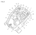
- This motor-driven steering lock device 100 is equipped with a case 103 comprising a case body 101 and a case cover 102 that covers a lower portion of the case body 101 as shown in Figs. 10 , 11 and 12 .
- a motor 104 a worm 106 that transmits rotation of an output shaft 105 of the motor 104, a worm wheel 107 that engages with this worm 106, a cam mechanism intergraded by rotation of the worm wheel 107, and a lock bolt 108 for locking that is moved linearly by this cam mechanism.
- Said worm wheel 107 is in a nearly cylindrical shape and is held rotatably within the case 103 by cylindrical parts 101a and 102a provided in the case body 101 and case cover 102 respectively.
- the lock bolt 108 is arranged to a direction of a rotating shaft in a manner to be able to go to and fro.
- case cover 102 is equipped with an engaging groove 114 to which an engaging convex portion 113 engages slidably in order to prevent the lock bolt 108 from moving together with the worm wheel 107, said convex portion being provided on an outer circumference of the lock bolt 108.
- Said cam mechanism comprises a cam groove 109 provided on a slant to the circumferential direction to an outer circumference of a cylindrical part 108a of the lock bolt 108, and a cam follower 111 held in a longitudinal groove 110 provided in an inner circumference of the worm wheel 107.
- Said cam mechanism is constituted wherein when the worm 106 and the worm wheel 107 are rotated by rotation of the motor 104, the lock bolt 108 moves to and fro a thrusting hole 112 of lock bolt of the case 103 by the movement of the cam follower 111 within the cam groove 109, and intergrades between a locked position engaging with the steering shaft (not shown) and an unlocked position not engaging with the steering shaft.
- thrust load is generated to the worm 106 by mating with the worm wheel 107, said worm being mounted on an output shaft of the motor.
- ends 117 and 118 of the case 103 are constituted as adjacent to a front end and rear end of the output shaft 105, thereby the rattling of the output shaft 105 of the motor to the direction of the thrust is prevented.
- ends 117 and 118 of the case 103 are constituted as adjacent to a front end and rear end of the output shaft 105, thereby the rattling of the output shaft 105 of the motor to the direction of the thrust is prevented.
- it is required to provide some gap between the outputs axis 105 of the motor and the ends 117 and 118 of the case 103.
- the lock bolt 108 is positioned to the case body 101 as the result, because the lock bolt 108 is constituted to be held inside the worm wheel 107, said worm wheel being held in the case body 101.
- the lock bolt 108 rotates slightly when the worm wheel 107 rotates, and there occurs a problem of loud hitting sound harsh to a user, generated by hitting of the engagement convex 113 and the engagement groove 114.
- a first preferred aim of the present invention is to provide a motor-driven actuator that prevents rattling of an output shaft of a motor and occurrence of hitting sound generated by the output shaft when the motor is driven.
- a second preferred aim of the present invention is to provide a motor-driven actuator that diminishes the generation of hitting sound due to error in case of assembling when the motor is driven.
- the motor-driven actuator provides inside a case a motor with an output shaft, a worm attached to said output shaft, and a rotation member equipped with a worm wheel that mates with said worm, wherein a bearing member equipped with a regulating face adjacent to a top end of said output shaft are provided, said bearing member being intergraded by biasing force of a spring that said regulating face pushes the top end of said output shaft into the direction of thrust of the output shaft.
- a gap between the output shaft of the motor and the bearing member can be reduced by moving the bearing member by the biasing force of the spring.
- This motor-driven actuator can be equipped with a motor cover, said cover holding said motor in a prescribed position in said case and having a fixed portion to prevent movement of said bearing member by assembling it to said case.
- This structure can prevent displacement of the bearing member during operation because the movement of the bearing member is prevented by the fixed portion of the motor cover assembled to the case, and because the bearing member is fixed to the case body in the status adjacent to the top end of the output shaft.
- This motor-driven actuator can be equipped with a housing in said case, said housing accommodating said bearing member movably, wherein operating direction of said bearing member biased by the biasing force of said spring in said housing can be set to cross with the direction of thrust of the output shaft of said motor.
- load to a fixed part of the fixed portion and the bearing member is reduced and release of the fixed situation of the bearing member by the fixed portion can be prevented.
- said regulating face of the bearing member can be provided in a manner to face orthogonally with the direction of trust of said output shaft, and the operating direction of said bearing member can be inclined at a prescribed angle to the regulating face.
- a center of the output shaft can be received by the regulating face in the front and deflection of the center of the output shaft can be prevented when the motor is driven, whereby improper mating of the worm and worm wheel can be prevented.
- the motor-driven actuator for steering locking for vehicles is provided with a lock bolt engaging with a steering shaft to prevent rotation of a steering; a rotation member holding said lock bolt inside to and fro to the direction of rotation; a cam mechanism having a cam groove and a cam follower and moving said lock bolt to the direction of the rotating shaft of said rotation member by moving said cam follower in said cam groove by the rotation of said rotation member, said cam groove disposed a one side of said lock bolt and said rotation member and inclined to the circumferential direction, and said cam follower disposed at the other side and sliding in said cam groove; a case body equipped with a lock bolt thrusting hole to trust said lock bolt externally; and a case cover closing an opening of said case body; wherein a rotation holding portion to hold rotatably said rotation member, and a rotation prevention portion engaging with an engagement portion of said lock bolt to prevent rotation of said lock bolt are disposed on the side of said case body.
- both of the rotation member and the lock bolt are positioned to the case body by equipping the rotation holding portion by which the rotation member holding the lock bolt to and fro is held rotatably at the side of the case body in which the lock bolt thrusting hole is equipped.
- rotation preventing portion is equipped at the side of the case body, said portion preventing rotation of the lock bolt, displacement of the lock bolt to the rotation preventing portion can be lesser.
- a gap between an engagement portion of the lock bolt and the rotation preventing portion can be set smaller.
- hitting sound can be lower in case of hitting by rotation of the lock bolt, and thereby comfort of a user can be enhanced.
- width of the lock bolt can be smaller and interference of the engagement portion with the rotation member can be prevented when assembled with the rotation member, by which easy assembling can be enhanced.
- rattling to the direction of thrust of the output shaft of the motor can be surely prevented and hitting sound by the output shaft can be prevented as a result when the motor is driven.
- displacement of the lock bolt to the rotation preventing portion can be lesser by equipping the rotation preventing portion at the side of the case body in which the rotation member and the lock bolt are positioned, said portion preventing the rotation of the lock bolt.
- a gap between an engagement portion of the lock bolt and the rotation preventing portion can be set smaller.
- hitting sound can be lesser in case of hitting by rotation of the lock bolt, and thereby comfort of a user can be enhanced.
- Figs. 1 and 2 show a motor-driven steering lock device (hereinafter referred to as "lock device") for which a motor-driven actuator according to the embodiment of the present invention is employed.
- lock device a motor-driven steering lock device for which a motor-driven actuator according to the embodiment of the present invention is employed.
- This lock device is disposed around a steering shaft rotating by rotating operation of a steering (not shown), and operated in communication with operation of a push switch or card key to start or stop an engine, etc.
- An engagement recess is formed on the steering shaft at a prescribed position to the circumferential direction as in the prior art.
- the lock device is equipped with a case 3 comprising a case body 1 with one end opened and a case cover 2, and inside them, a lock bolt 4, a rotation member 5, a cam mechanism to convert rotating movement of said rotation member 5 to to-and-fro movement of the lock bolt 4, a motor 6 that is an actuator, a motor cover 7, and a control panel 8 to control the operation of said motor 6.
- Said case body 1 as shown in Fig. 3 , is comprised of a container in a rectangular shape with one end opened, wherein a motor disposing portion 11 to dispose the motor 6, a lock mechanism disposing portion 12 to dispose the lock bolt 4 and the rotation member 5, a screw hole 13 to screw and fix the case cover 2, a boss for panel 14 to screw and fix the control panel 8, and a screw hole 15 for motor cover to screw and fix the motor cover 7 are formed.
- Said motor disposing portion 11 is for disposing the motor 6, and as shown in Figs. 3 and 5 , a motor housing recess 16 along a contour of the motor 6, a worm housing recess 17 housing a worm 69 attached to an output shaft 68 of the motor 6 in communication with the motor housing recess 16, and a shaft holding portion18 in an approximate U shape of the cross section, said portion rotatably holding a top end of the output shaft 68 of the motor 6 are formed linearly.
- a first housing portion 19 (housing portion) is provided at a front end of the shaft holding portion 18 (at a side opposing to the motor housing recess 16) in communication with said shaft holding portion 18, said housing portion housing a first bearing member 71 movably as described hereinbelow.
- the first housing portion 19 is disposed in recess in a nearly triangle shape, and has a first side 19a, a second side 19b and a third side 19c, said first side 19a being facing the end side of the shaft holding portion 18 and equipped in a longitudinal direction of the worm housing recess 17, that is, orthogonally with the direction of thrust of the output shaft 68 of the motor 6 when the motor 6 is attached, and the second side 19b being equipped at a slant at a prescribed angle to the first side 19a opposing said first side 19a, and the third side 19c being equipped nearly orthogonally to said second side 19b.
- a second housing portion 20 (illustrated in Fig. 5 ) is provided at the rear end of the motor housing recess 16, said portion being formed with the motor disposing portion 11 extended with a prescribed length at a position corresponding to the rear end of the output shaft 68 of the motor 6.
- Said lock mechanism disposing portion 12 is for disposing the lock bolt 4 and the rotation member 5, and equipped with a lock bolt thrusting hole 22 thrusting along the direction of attachment of the case cover 2.
- a rotation holding portion 23 is equipped around said lock bolt thrusting hole 22, said portion being projecting inwards to form a ring shape around a center of said lock bolt thrusting hole 22 to support the rotation member 5 rotatably.
- Two rotation preventing holes 24 (rotation preventing portion and lock bolt holding portion) are provided at opposing positions sandwiching said lock bolt thrusting hole 22 in the rotation holding portion 23, said holes 24 holding an engagement portion 50 of the lock bolt 4 (described below) in a manner moving to-and-fro.
- These rotation preventing holes 24 are with nearly square cross section and bored in parallel with the trusting direction of the lock bolt thrusting hole 22, said holes 24 being inclining to the opposing face as a face at the side to the diameter moves to the rear, and being set so as the cross sectional shape of an opening to be largest.
- a step 25 on which an upper face of the rotation member 5 abuts at a circumference of the rotation holding portion 23 is equipped and a regulating convex 26 is equipped at a prescribed position of the circumference of the step 25, said convex 26 regulating a scope of rotation of rotatable members and projecting to the direction of the diameter.
- Said case cover 2 is for closing an opening of the case body 1 and is equipped with a screw thrusting hole 31 at a position corresponding to the screw hole 13 of the case body 1 as shown in Fig. 4 .
- This case cover 2 is equipped with a cylindrical recess 3 at a position corresponding to the rotation holding portion 23 of the lock mechanism disposing portion 12, said recess holding a lower face of the rotation member 5.
- a spring attachment shaft 33 is equipped in projection at the center of the bottom of the cylindrical recess 32, said shaft 33 attaching and mating with outwards a spring 44 for lock bolt biasing the lock bolt 4 to the advancing direction.
- case cover 2 is equipped with a notch 34 at a side wall orthogonal with a side wall positioned at an opposite side to the cylindrical recess 32, said notch 34 being for exposing a connector 91 for electric connection.
- Said lock bolt 4 is disposed inside the rotation member 5 in a manner moving to-and-fro to the direction of the rotating shaft of the rotation member 5 and comprised of a lock member 41 in a shape of a square pole and a cam member 42, said lock member being able to thrust into the lock bolt thrusting hole 22 and said cam member moving said lock member to-and-fro as shown in Figs. 1 , 2 and 4 .
- An engagement convex 43 is equipped at an upper end of the lock member 41, said convex being thrust into and engaged with the engagement recess of the steering shaft.
- This lock member 41 is moved to-and-fro by the motor 6 via the rotation member 5 and the cam mechanism between a locked position and unlocked position, said locked position being advanced to the side of the steering shaft and engaging with the engagement recess, and the unlocked position going back and releasing the engagement.
- the engagement convex 43 is not coincident in the circumferential direction to the engagement recess, it is biased by the spring 44 for lock bolt to the advancing direction, and if coincident, it is advanced and engaged by the biasing force.
- an attachment convex 45 is projected and disposed at the lower position of the lock member 41 in order to be connected with the cam member 42.
- This attachment convex 45 is with a rectangular cross section, and a connecting hole 46 is equipped orthogonally with the axial direction.
- Said cam member 42 is in a nearly cylindrical shape disposed inside the rotation member 5 as hereinafter described.
- a thrusting hole 47 is equipped in the cam member 42, said hole thrusting from an upper end to lower end along the axial center of the lock member 41.
- This thrusting hole 47 is in a rectangular shape, the upper of which is coincident with the attachment convex 45, and the cam member 42 is equipped with a connecting hole 49 at a position corresponding to the connecting hole 46, said hole 49 thrusting a connecting pin 48.
- a lower portion of the thrusting hole 47 is in a conic shape in which an end of the spring 44 for lock member as a biasing member is inserted.
- An end of the spring 44 for lock bolt is positioned by an end of the lock member 41 attached to an upper portion of the thrusting hole 47.
- two engagement portions 50 are projected and disposed at an upper face of the cam member 42 at an opposing position sandwiching the thrusting hole 47, said portions advancing to-and-fro to the rotation preventing hole 24 of the case body 1, engaging to the circumferential direction and preventing rotation of the cam member 42 to the case body 1.
- These engagement portions 50 are in a shape substantially similar with the shape of the rotation preventing hole 24 of the case body 1, and equipped slightly smaller than the rotation preventing hole 24.
- these engagement portions 50 are projected and equipped in parallel with the advancing direction of the lock member 41 along a face substantially coincident with the outer circumference of the cam member 42, and formed with a tapered shape inclining to the opposing face as the face inside the radial direction advances to the projecting direction.
- engagement portions 50 are formed longer than the moving distance from the locked position to the unlocked position of the lock bolt 4. Even if the lock bolt 4 moves to the unlocked position, an engageable status of the rotation preventing hole 24 and the engagement portions 50 are maintained.
- the cam member 42 is preventing from inclining to an operating axis of the lock bolt 4 since the engagement portions 50 are held by the outer side of the rotation preventing hole 24 to the radial direction.
- a pair of cam grooves 51, 52 are equipped on the circumference of the cam member 42, opposing to the radial direction, said grooves being recessed in a nearly hemicycle shape and rotating in a spiral shape.
- the first cam groove 51 on one side is equipped displacing to the advancing direction of the lock bolt 4 against the second cam groove 52 on the other side, more than the height of the second cam groove 52, and displaced 180° to the circumferential direction.
- These cam grooves 51, 52 convert the rotating force of the rotation member 5 to linear movement of the lock bolt 4 via said cam member 42.
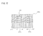
- Fig. 8 shows a development elevation of the outer circumference of the cam member 42, and vertical lines with equal interval in the drawing show angular lines every 10 degree.
- Upper and lower directions in the drawing show the height direction, and the upper side is equivalent to a top end of the lock bolt 4 (that is, steering shaft side) and the lower side to a rear side of the lock bolt 4.
- a prescribed area of one end (lower) of these cam grooves 51, 52 is set in advance at a locked area 53 (starting point) of the steering shaft by the lock bolt 4, and a prescribed area of other end (upper) as an unlocked area 54 (terminating point) of the steering shaft by the lock bolt 4.
- interference of the first cam groove 51 and the second cam groove 52 can be prevented since the first cam groove 51 is disposed displacing to the to-and-fro direction of the lock bolt 4 more than the height of the upper and lower direction from the locked area 53 to the unlocked area 54 of the second cam groove 52, and inclining angle and length of an inclining portion 55 of each of the cam grooves 51, 52 can be set freely.
- Said rotation member 5 is in a cylindrical shape with an inner diameter slightly larger than the cam member 42, and supported rotatably to the circumferential direction in a manner to be sandwiched between the case body 1 and the case cover 2 without being moved to the radial direction.
- the rotation member 5 is equipped with outer coupling portion 61 on one end (upper), said portion coupling with the outer circumferential portion of the rotation holding portion 23 of the case body 1.
- a worm wheel portion 62 is equipped on the upper portion of the rotation member 5, said portion projecting in the cross sectional shape of L from the outer circumference of the outer coupling portion 61 to the diametrical direction and forming a plurality of helical gears (not shown) extending along the radial direction outer-circumferentially.
- This worm wheel portion 62 rotates the rotation member 5 around the center of the axis line by engaging with dents of a worm 69 disposed to extend to the direction of the tangent line at the attaching condition to the case body 1 as shown in Fig. 5 .
- a regulating receptor 63 (shown in Fig. 4 ) is projected and equipped on the upper face of the worm wheel portion 62, said receptor engaging with the regulating convex 26 of the case body 1 and regulating the scope of rotation of the rotation member 5.
- a pair of longitudinal grooves 64, 65 is equipped on the inner circumference of the rotation member 5, said grooves extending along the radial direction from the lower end, and being recessed in nearly semicircle shape.
- the longitudinal groove 64 of one side is equipped extending to the position corresponding to the second cam groove 52, and the longitudinal groove 65 of other side is equipped extending to the position corresponding to the first cam groove 51, upper longer than the longitudinal groove 64 of one side.
- Said cam follower 67 is comprised of a steel ball in the spherical shape, and is disposed to each longitudinal grooves 64, 65 of the rotation member 5 respectively as shown in Fig. 2 .
- lock bolt 4 is moved to-and-fro along the center of the rotating shaft of the rotation member 5 via said cam member 42.
- this embodiment is constituted wherein rotating force of the rotation member 5 is transmitted to the lock bolt 4, the cam groove 51, 52 are equipped on the lock bolt 4, and the cam follower 67 is disposed between the rotating member 5 and cam member 42, operating as a cam mechanism to move said lock bolt 4 between the locked position and unlocked position.
- Said motor 6 is a power source to move the lock bolt 4 and is disposed at the motor housing recess 16 of the case body 1 via the motor cover 7.
- This motor 6 can conduct normal rotation to advance the lock bolt 4 and reverse rotation to set back the lock bolt 4.
- the output shaft 68 is equipped with the worm 69, said worm being a screw gear with spiral dents (not shown) along the radial direction outer-circumferentially.
- the top end and rear end of the output shaft 68 abut on a first bearing member 71 and second bearing member 77 described hereinbelow, and regulate rattling to the direction of thrust of the output shaft 68.
- the first bearing member 71 is housed in the first housing portion 19 of the case body 1, and abuts on the top end of the output shaft 68 of the motor 6, and prevents rattling generated to the direction of thrust of the output shaft 68, said member being formed with resin material such as polyacetal.
- the first bearing member 71 is a bloc with the cross section of a wedge, and a spring positioning portion 72 is projected and equipped on a broader end section, said portion positioning a spring 75 and the interval between both sides becomes narrower as it goes to the other end.
- Opposing angle of both sides is set similar with the opposing angle of the first side 19a and the second side 19b of the first housing portion 19, and a face corresponding to the first side 19a is a regulating face 74 abutting on the top end of the output shaft 68 of the motor 6 (see Fig. 5 ).
- the first bearing member 71 when the first bearing member 71 is disposed along the first side 19a of the first housing portion 19, it is constituted so that the regulating face 74 faces at all times orthogonally with the direction of thrust of the output shaft 68 of the motor 6.
- first bearing member 71 is inclining to the side of the motor 6 as the second side 19b of the first housing portion 19 goes to the advancing direction, and biased by biasing force of the spring 75 along the direction of the face of the second side 19b.
- the first bearing member 71 intergrades to push the output shaft 68 of the motor 6 toward the direction of thrust by biasing force of the spring 75.
- the upper face of the first bearing member 71 is equipped with a deformed portion 76 deformable, on which a mountain of the output shaft 68 of the motor 6 extending to the direction of thrust is arranged in plural orthogonally with the direction of thrust.
- the second bearing member 77 is housed in the second housing portion 20 of the case body 1 and abuts on the rear end of the output shaft 68 of the motor 6, and prevents rattling generated to the direction of thrust of the output shaft 68, said member being formed with resin material such as polyacetal.
- This second bearing member 77 is in a shape of substantial cuboid and inserted and fixed in the second housing portion 20.
- the motor cover 7 is to accommodate the motor 6 undetachably in the motor disposing portion 11 of the case body 1 wherein, as shown in Fig. 6 , a motor housing recess 81 along the contour of the motor 6, motor holding portion 82 abutting on a part of the motor 6, a worm housing recess 83 to accommodate the worm 69, and an shaft holding portion 84 to prevent the output shaft 68 of the motor 6 from slipping out from the shaft holding portion 18 are formed in linear arrangement from the rear end to the top end.
- a fixing portion 85 is equipped on a front of the shaft holding portion 84, said fixing portion projecting a contour line with a lozenged cross section.
- This fixing portion 85 is pushed to the deformed portion 76 of the first bearing member 71 when the motor cover 7 is assembled to the case body 1.
- the deformed portion 76 of the first bearing member 71 is deformed and the fixing portion 85 is broken into the deformed portion 76, and the first bearing member 71 is fixed at its position, whereby displacement of the first bearing member 71 prevented.
- an electrode thrusting hole 86 is equipped in the motor housing recess 81, said hole thrusting the a motor electrode (not shown) extending from the control panel 8 and connected to plus and minus terminals of the motor 6.
- a second bearing member holding portion 87 is projected and equipped on the rear side of the motor housing recess 81, said portion abutting on the second bearing member 77 and prevent falling out of the second bearing member 77.
- a thrusting hole 88 is equipped on the side of the worm housing recess 83, said hole thrusting and disposing the lock bolt 4 and rotation member 5.
- Screw holes 89 are formed at the position corresponding to the screw holes 15 for motor cover of case body 1 respectively.
- Said control panel 8 is implemented with a micro computer (CPU) (not shown) controlling the movement of the motor 6, a micro switch (not shown) to detect the advancing position of the lock bolt 4 by the rotation bolt 5, a connector 91 to connect to a main micro computer (ECU) mounted on a vehicle, and a motor electrode (not shown) to be connected to an external battery by the connector 91.
- CPU central processing unit
- ECU main micro computer
- this control panel 8 is equipped with a thrusting hole 92, said hole thrusting and disposing said lock bolt 4 and rotation member 5, and at the position corresponding to the boss 14 for panel of the case body a screw hole 93 is formed to cramp screws when assembled to the case body 1.
- the lock bolt 4 and cam follower 67 are assembled to the rotation member 5 at first, said lock bolt connecting integrally the lock member 41 and cam member 42.
- the lock bolt 4 is assembled thrusting from the lower opening to the upper opening of the rotation member 5.
- the engagement portion 50 of the lock bolt 4 does not interfere with the rotation member 50 when assembled because the engagement portion 50 of the lock bolt is projected and equipped to the projecting side of the lock member 41.
- the motor cover 7 is disposed and fixed to the case body 1 by screw cramping.
- control panel 8 is disposed at the opening of the case body 1 and fixed to the case body 1 by screw cramping.
- case cover 2 is attached and fixed to the case body 1 by screw cramping.
- a gap between the first bearing member 71 and the top end of the output shaft 68 can be determined appropriately.
- first bearing member 71 is disposed movably to the first housing portion 19 to the crossing direction with the direction of thrust of the output shaft 68, part of load applying to the first bearing member 71 is received by the second side 19b of the first housing portion 19, and the remaining load acts the first bearing member 71 to oppose the biasing force of the spring 75 even if strong load acts the output shaft 68 of the motor 6 to the direction of thrust.
- the center of the axis of the output shaft 68 can be received at the front and displacement of the center of the axis of the output shaft 68 can be prevented when the motor is activated.
- the lock device according to this embodiment is assembled as mentioned above.
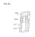
- the second bearing member 77 is constituted as shown in Fig. 5a , an appropriate gap can be disposed between the first and second bearing members 71, 77 and the output shaft 68 of the motor 6.
- the second bearing member 77 is put in an interim housing condition that its top end is inserted in the second housing portion 20, and the rear end of the output shaft 68 is abutted on a position of a dotted line 68a as shown in Fig. 5a .
- the front end of the output shaft 68 is abutted on the first bearing member 71.
- an appropriate gap as a bearing can be disposed between the first and second bearing members 71, 77 and the output shaft 68 corresponding to the recess 77a of the second bearing member 77.
- an interval of 0.2mm between the first bearing member 71 and the output shaft 68 can be set.
- the motor 6 is driven in reverse rotation in order to put the lock device in the locked condition.
- the worm 69 attached to the output shaft 68 rotates counterclockwise seen from the motor 6, and the rotation member 5 in which the worm wheel 62 engages with the worm 69 starts to rotate to the locked direction (in Fig. 5 , counterclockwise direction).
- the top end of the lock bolt 4 advances to and engages with the engagement recess of the steering shaft, and the rotation of the steering shaft is regulated and the steering is put in a locked condition.
- This rotation of the lock bolt 4 is prevented by engagement of the engagement portion 50 of the lock bolt 4 with the rotation prevention hole 24, however, if there is a gap between the engagement portion 50 and the rotation prevention hole 24, the scope of rotation of the lock bolt 4 becomes larger, and hitting sound becomes louder when the engagement portion 50 hit the rotation prevention hole 24.
- the rotation member 5 is coupled outwards with the rotation holding portion 23 disposed at the case body 1 and held as rotatably, and the lock bolt 4 is held by the circumferential face of the rotation member 5.
- the lock bolt 4 is in a condition that it is positioned indirectly by the case body 1 via the rotation member 5.
- a point of action to which force is applied from the cam follower 67 is displaced to the direction of the acting axis of the lock bolt 4 since two cam grooves 51, 52 are disposed displacing to the direction of the acting axis of the lock bolt 4.
- the gap between the engagement portion 50 and the circumferential radial side of the rotation prevention hole 24 displacement of the lock bolt 4 to the rotation prevention hole 24 can be smaller by disposing the rotation prevention hole 24 at the side of the case body 1 by the same reason mentioned above. As a result, the gap between the engagement portion 50 and the circumferential radial side of the rotation prevention hole 24 can be smaller. By this, inclination of the lock bolt 4 can be further prevented.
- the steering lock device according to the present invention is not limited to the construction of the embodiment mentioned above but may be subject to various change.
- lock member 41 and cam member 42 are connected to form the lock bolt 4, while the lock member 41 and cam member 42 can be integrally formed.
- the cam mechanism is constituted with the cam grooves 51, 52 disposed on the lock bolt 4, and the cam follower 67 disposed between the rotation member 5 and cam member 42.
- the cam mechanism can be constituted by that the cam grooves 51, 52 are disposed on an inner circumference of the rotation member 5 and the cam follower 67 is fixed on the side of the lock bolt 4.
- cam follower 67 is not limited to steel balls in a spherical shape but pins or the like can be fixed on the rotation member 5 or lock bolt 4, for example.
- the first cam groove 51 is constituted to be disposed displacing to the advancing direction of the lock bolt 4 against the second cam groove 52, higher than the height of the second cam groove 52, but not limited to it: the first cam groove 51 can be disposed displacing slightly to the advancing direction of the lock bolt 4 (lower than the height of the second cam groove 52).
- the engagement portion 50 of the lock bolt 4 is projected and equipped in parallel with the advancing direction of the lock member 41 and the rotation prevention portion of the case body 1 is constituted as the rotation prevention hole 24 to receive said engagement portion 50 but without limitation to it: the engagement portion 50 can be a recess and the rotation prevention portion can be a convex projecting to the engagement portion 50, for example.
- the regulating face of the first bearing member 71 can be equipped inclining the output shaft 68 at a prescribed angle to a face orthogonal with the direction of thrust.
- the deformed portion 76 is equipped on the first bearing member 71 and the fixed portion 85 is equipped on the motor cover 7 as well, but not without limitation to it: for example, a rubber or double adhesive tape or the like is affixed on the motor cover 7 or the first bearing member 71 and thereby the first bearing member 71 is fixed by cohesion or adhesion of the members of the other part.
- the motor can be held undetachably to the case body by the case cover closing the opening of the case body and said fixed portion can be equipped on the case cover.
- the structure of the present invention can be employed for a motor-driven actuator in every field.
Landscapes
- Engineering & Computer Science (AREA)
- Mechanical Engineering (AREA)
- Multimedia (AREA)
- Lock And Its Accessories (AREA)
- Connection Of Motors, Electrical Generators, Mechanical Devices, And The Like (AREA)
Abstract
Description
- The present invention relates to a motor-driven actuator used for vehicles, and the like.
- A motor-driven actuator is housed in a motor-driven steering lock device by which a steering shaft of a vehicle is locked or unlocked by driving force of a motor.
- A motor-driven steering lock device of this type of the prior arts is shown in Japanese Laid-Open Patent Application Gazette No.
2000-015984 - This motor-driven
steering lock device 100 is equipped with acase 103 comprising acase body 101 and acase cover 102 that covers a lower portion of thecase body 101 as shown inFigs. 10 ,11 and12 . - In said
case 103, amotor 104, aworm 106 that transmits rotation of anoutput shaft 105 of themotor 104, aworm wheel 107 that engages with thisworm 106, a cam mechanism intergraded by rotation of theworm wheel 107, and alock bolt 108 for locking that is moved linearly by this cam mechanism. - Said
worm wheel 107 is in a nearly cylindrical shape and is held rotatably within thecase 103 bycylindrical parts 101a and 102a provided in thecase body 101 andcase cover 102 respectively. - Inside the
worm wheel 107, thelock bolt 108 is arranged to a direction of a rotating shaft in a manner to be able to go to and fro. - Further, the
case cover 102 is equipped with anengaging groove 114 to which an engagingconvex portion 113 engages slidably in order to prevent thelock bolt 108 from moving together with theworm wheel 107, said convex portion being provided on an outer circumference of thelock bolt 108. - Said cam mechanism comprises a
cam groove 109 provided on a slant to the circumferential direction to an outer circumference of acylindrical part 108a of thelock bolt 108, and acam follower 111 held in alongitudinal groove 110 provided in an inner circumference of theworm wheel 107. Said cam mechanism is constituted wherein when theworm 106 and theworm wheel 107 are rotated by rotation of themotor 104, thelock bolt 108 moves to and fro athrusting hole 112 of lock bolt of thecase 103 by the movement of thecam follower 111 within thecam groove 109, and intergrades between a locked position engaging with the steering shaft (not shown) and an unlocked position not engaging with the steering shaft. - In the motor-driven
steering lock device 100 disclosed in this Publication of Patent Application, thrust load is generated to theworm 106 by mating with theworm wheel 107, said worm being mounted on an output shaft of the motor. - For example, in
Fig. 10 , when the output shaft andworm 106 are rotated normally in a manner that theworm wheel 107 is rotated counterclockwise, thrust reactive force applied to theworm 106 from theworm wheel 107 acts to the direction of the thrust toward a side from which theoutput shaft 105 is projected from the motor. - On the other hand, when the
output shaft 105 andworm 106 are rotated reversely in order for theworm wheel 107 to rotate clockwise, the thrust reactive force applied to theworm 106 from theworm wheel 107 acts theoutput shaft 105 to the direction of the trust toward the motor. - This reversal movement of the motor generates to the
output shaft 105 of the motor the rattling to the direction of the thrust. It is one cause of a shorter life of the motor. - In this motor-driven
steering lock device 100,ends case 103, said case housing the motor, are constituted as adjacent to a front end and rear end of theoutput shaft 105, thereby the rattling of theoutput shaft 105 of the motor to the direction of the thrust is prevented. However, due to dispersion of dimensions of thecase 103 when manufactured, it is required to provide some gap between theoutputs axis 105 of the motor and theends case 103. - By this reason, when a gap becomes larger due to the dispersion of dimensions, the structure of the motor-driven
steering lock device 100 in the Publication of Patent Application above can not prevent the rattling caused by the gap to the direction of the thrust. - Accordingly, there has been a problem that hitting sound (percussive noise) generated by hitting of the
output shaft 105 to thecase 103 cannot be prevented when the motor is driven. - Further, in the structure of the motor-driven
steering lock device 100 as mentioned above, when thecase body 101 and acase cover 102 is assembled to form thecase 103, it is difficult to match the rotating shaft of respectivecylindrical part 101a and 102a, said cylindrical parts holding theworm wheel 107 rotatably, due to error in case of assembling, etc. since thecase body 101 and thecase cover 102 are constituted separately. - To absorb this mismatch of the rotating shafts, some gap is provided between the
cylindrical part 102a at the side of thecase cover 102 and theworm wheel 107, while theworm wheel 107 that accommodates thelock bolt 108 inside is held rotatably by the cylindrical part 101a at the side of thecase body 101 because thelock bolt 108 pierces into the lockbolt thrusting hole 112 of thecase body 101. - In this case, the
lock bolt 108 is positioned to thecase body 101 as the result, because thelock bolt 108 is constituted to be held inside theworm wheel 107, said worm wheel being held in thecase body 101. - Accordingly, likewise as mentioned above, as there might be displacement in case of assembling between an engagement convex 113 of the
lock bolt 108, said convex being positioned in thecase body 1, and anengagement groove 114 of thecase cover 102 due to affect of error in case of assembling of thecase body 101 and thecase cover 102, it is required to provide some gap between the engagement convex 113 and theengagement groove 114. - However, if such a gap is provided, the
lock bolt 108 rotates slightly when theworm wheel 107 rotates, and there occurs a problem of loud hitting sound harsh to a user, generated by hitting of the engagement convex 113 and theengagement groove 114. - In view of the problems mentioned above, a first preferred aim of the present invention is to provide a motor-driven actuator that prevents rattling of an output shaft of a motor and occurrence of hitting sound generated by the output shaft when the motor is driven.
- Further, a second preferred aim of the present invention is to provide a motor-driven actuator that diminishes the generation of hitting sound due to error in case of assembling when the motor is driven.
- In a first aspect of the invention, the motor-driven actuator
according to the present invention provides inside a case a motor with an output shaft, a worm attached to said output shaft, and a rotation member equipped with a worm wheel that mates with said worm, wherein a bearing member equipped with a regulating face adjacent to a top end of said output shaft are provided, said bearing member being intergraded by biasing force of a spring that said regulating face pushes the top end of said output shaft into the direction of thrust of the output shaft. - According to this motor-driven actuator, a gap between the output shaft of the motor and the bearing member can be reduced by moving the bearing member by the biasing force of the spring.
- By this, a gap of the output shaft of the motor can be reduced by the regulating face of the bearing member, and thereby rattling of the output shaft to the direction of thrust can be prevented surely.
- As a result, generation of hitting sound by the output shaft when the motor is driven can be prevented.
- This motor-driven actuator can be equipped with a motor cover, said cover holding said motor in a prescribed position in said case and having a fixed portion to prevent movement of said bearing member by assembling it to said case.
- This structure can prevent displacement of the bearing member during operation because the movement of the bearing member is prevented by the fixed portion of the motor cover assembled to the case, and because the bearing member is fixed to the case body in the status adjacent to the top end of the output shaft.
- This motor-driven actuator can be equipped with a housing in said case, said housing accommodating said bearing member movably, wherein operating direction of said bearing member biased by the biasing force of said spring in said housing can be set to cross with the direction of thrust of the output shaft of said motor.
- If set as above, a part of loading applied to the bearing member is received by the side of the housing and the remaining load operates to the bearing member as to oppose the biasing force of the spring even if strong thrust load operates to the output shaft of the motor to the direction of trust since the bearing member is arranged movably in the housing to the crossing direction with the direction of thrust of the output shaft.
- That is, displacement of the bearing member can be prevented since the load operating to the direction to move the bearing member as opposing the biasing force of the spring is reduced.
- Further, load to a fixed part of the fixed portion and the bearing member is reduced and release of the fixed situation of the bearing member by the fixed portion can be prevented.
- In the motor-driven actuator, said regulating face of the bearing member can be provided in a manner to face orthogonally with the direction of trust of said output shaft, and the operating direction of said bearing member can be inclined at a prescribed angle to the regulating face.
- If constituted as above, a center of the output shaft can be received by the regulating face in the front and deflection of the center of the output shaft can be prevented when the motor is driven, whereby improper mating of the worm and worm wheel can be prevented.
- Further, in a second aspect of the invention, the motor-driven
actuator for steering locking for vehicles according to the present invention is provided with a lock bolt engaging with a steering shaft to prevent rotation of a steering; a rotation member holding said lock bolt inside to and fro to the direction of rotation; a cam mechanism having a cam groove and a cam follower and moving said lock bolt to the direction of the rotating shaft of said rotation member by moving said cam follower in said cam groove by the rotation of said rotation member, said cam groove disposed a one side of said lock bolt and said rotation member and inclined to the circumferential direction, and said cam follower disposed at the other side and sliding in said cam groove; a case body equipped with a lock bolt thrusting hole to trust said lock bolt externally; and a case cover closing an opening of said case body; wherein a rotation holding portion to hold rotatably said rotation member, and a rotation prevention portion engaging with an engagement portion of said lock bolt to prevent rotation of said lock bolt are disposed on the side of said case body. - According to the motor-driven steering lock device, both of the rotation member and the lock bolt are positioned to the case body by equipping the rotation holding portion by which the rotation member holding the lock bolt to and fro is held rotatably at the side of the case body in which the lock bolt thrusting hole is equipped.
- If the rotation preventing portion is equipped at the side of the case body, said portion preventing rotation of the lock bolt, displacement of the lock bolt to the rotation preventing portion can be lesser.
- By this, a gap between an engagement portion of the lock bolt and the rotation preventing portion can be set smaller.
- As a result, hitting sound can be lower in case of hitting by rotation of the lock bolt, and thereby comfort of a user can be enhanced.
- It is favorable in the motor-driven steering lock device that said engagement portion is equipped projecting in the advancing direction of said lock bolt.
- By this, width of the lock bolt can be smaller and interference of the engagement portion with the rotation member can be prevented when assembled with the rotation member, by which easy assembling can be enhanced.
- As stated above, according to the motor-driven actuator of the present invention, rattling to the direction of thrust of the output shaft of the motor can be surely prevented and hitting sound by the output shaft can be prevented as a result when the motor is driven.
- Further, according to the motor-driven actuator of the present invention, displacement of the lock bolt to the rotation preventing portion can be lesser by equipping the rotation preventing portion at the side of the case body in which the rotation member and the lock bolt are positioned, said portion preventing the rotation of the lock bolt.
- By this, a gap between an engagement portion of the lock bolt and the rotation preventing portion can be set smaller.
- As a result, hitting sound can be lesser in case of hitting by rotation of the lock bolt, and thereby comfort of a user can be enhanced.
- In the drawings:
-
Fig. 1 is an exploded perspective view showing a motor-driven steering lock device employing a motor-driven actuator according to an embodiment of the present invention; -
Fig. 2 is a cross sectional view showing a locked status of the motor-driven steering lock device inFig. 1 ; -
Fig. 3 is a perspective view seen from an opening side of a case body; -
Fig. 4 is an exploded perspective view of a cam mechanism and a case cover; -
Fig. 5 is a bottom view seen from lower portion ofFig. 2 in which the case cover and a motor cover are removed; -
Fig. 5a is a perspective view of a second bearing member equipped in the motor-driven steering lock device mentioned above; -
Fig. 6 is a perspective view of the motor cover; -
Fig. 7 is a bottom view showing a status of attaching the motor cover inFig. 5 ; -
Fig. 8 is a development elevation of an outer circumference of a cam member of a lock bolt; -
Fig. 9 is a cross sectional view of an unlocked status of the motor-driven steering lock device inFig. 1 ; -
Fig. 10 is a transverse sectional view of a motor-driven steering lock device according to the prior art; -
Fig. 11 is a longitudinal sectional view of a motor-driven steering lock device according to the prior art; and -
Fig. 12 is a development elevation of an outer circumference of a lock bolt of a motor-driven steering lock device according to the prior art. - Now, embodiment of the present invention is described referring to the drawings.
-
Figs. 1 and2 show a motor-driven steering lock device (hereinafter referred to as "lock device") for which a motor-driven actuator according to the embodiment of the present invention is employed. - This lock device is disposed around a steering shaft rotating by rotating operation of a steering (not shown), and operated in communication with operation of a push switch or card key to start or stop an engine, etc.
- An engagement recess is formed on the steering shaft at a prescribed position to the circumferential direction as in the prior art.
- The lock device according to this embodiment is equipped with a
case 3 comprising acase body 1 with one end opened and acase cover 2, and inside them, alock bolt 4, arotation member 5, a cam mechanism to convert rotating movement of saidrotation member 5 to to-and-fro movement of thelock bolt 4, amotor 6 that is an actuator, amotor cover 7, and acontrol panel 8 to control the operation of saidmotor 6. - Said
case body 1, as shown inFig. 3 , is comprised of a container in a rectangular shape with one end opened, wherein amotor disposing portion 11 to dispose themotor 6, a lockmechanism disposing portion 12 to dispose thelock bolt 4 and therotation member 5, ascrew hole 13 to screw and fix thecase cover 2, a boss forpanel 14 to screw and fix thecontrol panel 8, and ascrew hole 15 for motor cover to screw and fix themotor cover 7 are formed. - Said
motor disposing portion 11 is for disposing themotor 6, and as shown inFigs. 3 and5 , amotor housing recess 16 along a contour of themotor 6, aworm housing recess 17 housing aworm 69 attached to anoutput shaft 68 of themotor 6 in communication with themotor housing recess 16, and a shaft holding portion18 in an approximate U shape of the cross section, said portion rotatably holding a top end of theoutput shaft 68 of themotor 6 are formed linearly. - A first housing portion 19 (housing portion) is provided at a front end of the shaft holding portion 18 (at a side opposing to the motor housing recess 16) in communication with said
shaft holding portion 18, said housing portion housing afirst bearing member 71 movably as described hereinbelow. - The
first housing portion 19 is disposed in recess in a nearly triangle shape, and has afirst side 19a, asecond side 19b and athird side 19c, saidfirst side 19a being facing the end side of theshaft holding portion 18 and equipped in a longitudinal direction of theworm housing recess 17, that is, orthogonally with the direction of thrust of theoutput shaft 68 of themotor 6 when themotor 6 is attached, and thesecond side 19b being equipped at a slant at a prescribed angle to thefirst side 19a opposing saidfirst side 19a, and thethird side 19c being equipped nearly orthogonally to saidsecond side 19b. - On the other hand, a second housing portion 20 (illustrated in
Fig. 5 ) is provided at the rear end of themotor housing recess 16, said portion being formed with themotor disposing portion 11 extended with a prescribed length at a position corresponding to the rear end of theoutput shaft 68 of themotor 6. - Said lock
mechanism disposing portion 12 is for disposing thelock bolt 4 and therotation member 5, and equipped with a lockbolt thrusting hole 22 thrusting along the direction of attachment of thecase cover 2. - Further, a
rotation holding portion 23 is equipped around said lockbolt thrusting hole 22, said portion being projecting inwards to form a ring shape around a center of said lockbolt thrusting hole 22 to support therotation member 5 rotatably. - Two rotation preventing holes 24 (rotation preventing portion and lock bolt holding portion) are provided at opposing positions sandwiching said lock
bolt thrusting hole 22 in therotation holding portion 23, saidholes 24 holding anengagement portion 50 of the lock bolt 4 (described below) in a manner moving to-and-fro. - These
rotation preventing holes 24 are with nearly square cross section and bored in parallel with the trusting direction of the lockbolt thrusting hole 22, saidholes 24 being inclining to the opposing face as a face at the side to the diameter moves to the rear, and being set so as the cross sectional shape of an opening to be largest. - Further, a
step 25 on which an upper face of therotation member 5 abuts at a circumference of therotation holding portion 23 is equipped and a regulating convex 26 is equipped at a prescribed position of the circumference of thestep 25, said convex 26 regulating a scope of rotation of rotatable members and projecting to the direction of the diameter. - Said
case cover 2 is for closing an opening of thecase body 1 and is equipped with ascrew thrusting hole 31 at a position corresponding to thescrew hole 13 of thecase body 1 as shown inFig. 4 . - This case cover 2 is equipped with a
cylindrical recess 3 at a position corresponding to therotation holding portion 23 of the lockmechanism disposing portion 12, said recess holding a lower face of therotation member 5. - A
spring attachment shaft 33 is equipped in projection at the center of the bottom of thecylindrical recess 32, saidshaft 33 attaching and mating with outwards aspring 44 for lock bolt biasing thelock bolt 4 to the advancing direction. - Further, the
case cover 2 is equipped with anotch 34 at a side wall orthogonal with a side wall positioned at an opposite side to thecylindrical recess 32, saidnotch 34 being for exposing aconnector 91 for electric connection. - Said
lock bolt 4 is disposed inside therotation member 5 in a manner moving to-and-fro to the direction of the rotating shaft of therotation member 5 and comprised of alock member 41 in a shape of a square pole and acam member 42, said lock member being able to thrust into the lockbolt thrusting hole 22 and said cam member moving said lock member to-and-fro as shown inFigs. 1 ,2 and4 . - An engagement convex 43 is equipped at an upper end of the
lock member 41, said convex being thrust into and engaged with the engagement recess of the steering shaft. - This
lock member 41 is moved to-and-fro by themotor 6 via therotation member 5 and the cam mechanism between a locked position and unlocked position, said locked position being advanced to the side of the steering shaft and engaging with the engagement recess, and the unlocked position going back and releasing the engagement. - Further, if the engagement convex 43 is not coincident in the circumferential direction to the engagement recess, it is biased by the
spring 44 for lock bolt to the advancing direction, and if coincident, it is advanced and engaged by the biasing force. - As shown in
Fig. 2 , an attachment convex 45 is projected and disposed at the lower position of thelock member 41 in order to be connected with thecam member 42. - This attachment convex 45 is with a rectangular cross section, and a connecting
hole 46 is equipped orthogonally with the axial direction. - Said
cam member 42 is in a nearly cylindrical shape disposed inside therotation member 5 as hereinafter described. - A thrusting
hole 47 is equipped in thecam member 42, said hole thrusting from an upper end to lower end along the axial center of thelock member 41. - This thrusting
hole 47 is in a rectangular shape, the upper of which is coincident with the attachment convex 45, and thecam member 42 is equipped with a connectinghole 49 at a position corresponding to the connectinghole 46, saidhole 49 thrusting a connectingpin 48. - Further, a lower portion of the thrusting
hole 47 is in a conic shape in which an end of thespring 44 for lock member as a biasing member is inserted. - An end of the
spring 44 for lock bolt is positioned by an end of thelock member 41 attached to an upper portion of the thrustinghole 47. - Further, two
engagement portions 50 are projected and disposed at an upper face of thecam member 42 at an opposing position sandwiching the thrustinghole 47, said portions advancing to-and-fro to therotation preventing hole 24 of thecase body 1, engaging to the circumferential direction and preventing rotation of thecam member 42 to thecase body 1. - These
engagement portions 50 are in a shape substantially similar with the shape of therotation preventing hole 24 of thecase body 1, and equipped slightly smaller than therotation preventing hole 24. - More specifically, these
engagement portions 50 are projected and equipped in parallel with the advancing direction of thelock member 41 along a face substantially coincident with the outer circumference of thecam member 42, and formed with a tapered shape inclining to the opposing face as the face inside the radial direction advances to the projecting direction. - Further, these
engagement portions 50 are formed longer than the moving distance from the locked position to the unlocked position of thelock bolt 4. Even if thelock bolt 4 moves to the unlocked position, an engageable status of therotation preventing hole 24 and theengagement portions 50 are maintained. Thecam member 42 is preventing from inclining to an operating axis of thelock bolt 4 since theengagement portions 50 are held by the outer side of therotation preventing hole 24 to the radial direction. - A pair of
cam grooves cam member 42, opposing to the radial direction, said grooves being recessed in a nearly hemicycle shape and rotating in a spiral shape. Thefirst cam groove 51 on one side is equipped displacing to the advancing direction of thelock bolt 4 against thesecond cam groove 52 on the other side, more than the height of thesecond cam groove 52, and displaced 180° to the circumferential direction. Thesecam grooves rotation member 5 to linear movement of thelock bolt 4 via saidcam member 42. -
Fig. 8 shows a development elevation of the outer circumference of thecam member 42, and vertical lines with equal interval in the drawing show angular lines every 10 degree. Upper and lower directions in the drawing show the height direction, and the upper side is equivalent to a top end of the lock bolt 4 (that is, steering shaft side) and the lower side to a rear side of thelock bolt 4. - A prescribed area of one end (lower) of these
cam grooves lock bolt 4, and a prescribed area of other end (upper) as an unlocked area 54 (terminating point) of the steering shaft by thelock bolt 4. - And, inclining angle of the inclining
portion 55 between these lockedarea 53 andunlocked area 54 sets the speed of moving to-and-fro of thelock bolt 4. - In this embodiment, interference of the
first cam groove 51 and thesecond cam groove 52 can be prevented since thefirst cam groove 51 is disposed displacing to the to-and-fro direction of thelock bolt 4 more than the height of the upper and lower direction from the lockedarea 53 to theunlocked area 54 of thesecond cam groove 52, and inclining angle and length of an incliningportion 55 of each of thecam grooves - By this reason, it is not necessary to change the inclining angle of the inclining
portion 55 along the way due to shortage of a space, and the angle can be set at certain angle. - As mentioned above, if the inclining angle of the inclining
portion 55 is set constant, generation of hitting sound of acam follower 67 with a step can be eliminated since thecam follower 67 does not hit the step in process of inclining. - Said
rotation member 5 is in a cylindrical shape with an inner diameter slightly larger than thecam member 42, and supported rotatably to the circumferential direction in a manner to be sandwiched between thecase body 1 and thecase cover 2 without being moved to the radial direction. - More concretely, as shown in
Figs. 2 and4 , therotation member 5 is equipped withouter coupling portion 61 on one end (upper), said portion coupling with the outer circumferential portion of therotation holding portion 23 of thecase body 1. - Further, a
worm wheel portion 62 is equipped on the upper portion of therotation member 5, said portion projecting in the cross sectional shape of L from the outer circumference of theouter coupling portion 61 to the diametrical direction and forming a plurality of helical gears (not shown) extending along the radial direction outer-circumferentially. - This
worm wheel portion 62 rotates therotation member 5 around the center of the axis line by engaging with dents of aworm 69 disposed to extend to the direction of the tangent line at the attaching condition to thecase body 1 as shown inFig. 5 . - Further, a regulating receptor 63 (shown in
Fig. 4 ) is projected and equipped on the upper face of theworm wheel portion 62, said receptor engaging with the regulating convex 26 of thecase body 1 and regulating the scope of rotation of therotation member 5. - Furthermore, a pair of
longitudinal grooves rotation member 5, said grooves extending along the radial direction from the lower end, and being recessed in nearly semicircle shape. - The
longitudinal groove 64 of one side is equipped extending to the position corresponding to thesecond cam groove 52, and thelongitudinal groove 65 of other side is equipped extending to the position corresponding to thefirst cam groove 51, upper longer than thelongitudinal groove 64 of one side. - Said
cam follower 67 is comprised of a steel ball in the spherical shape, and is disposed to eachlongitudinal grooves rotation member 5 respectively as shown inFig. 2 . - When the
rotation member 5 is rotated in the condition that projecting portions form thelongitudinal grooves cam groove cam member 42, it slides along eachcam groove cam member 42 regulated not to rotate by rotation of thelongitudinal grooves - Accordingly, the
lock bolt 4 is moved to-and-fro along the center of the rotating shaft of therotation member 5 via saidcam member 42. - As described above, this embodiment is constituted wherein rotating force of the
rotation member 5 is transmitted to thelock bolt 4, thecam groove lock bolt 4, and thecam follower 67 is disposed between the rotatingmember 5 andcam member 42, operating as a cam mechanism to move saidlock bolt 4 between the locked position and unlocked position. - Said
motor 6 is a power source to move thelock bolt 4 and is disposed at themotor housing recess 16 of thecase body 1 via themotor cover 7. - This
motor 6 can conduct normal rotation to advance thelock bolt 4 and reverse rotation to set back thelock bolt 4. As shown inFig. 5 , theoutput shaft 68 is equipped with theworm 69, said worm being a screw gear with spiral dents (not shown) along the radial direction outer-circumferentially. - The top end and rear end of the
output shaft 68 abut on afirst bearing member 71 andsecond bearing member 77 described hereinbelow, and regulate rattling to the direction of thrust of theoutput shaft 68. - The
first bearing member 71 is housed in thefirst housing portion 19 of thecase body 1, and abuts on the top end of theoutput shaft 68 of themotor 6, and prevents rattling generated to the direction of thrust of theoutput shaft 68, said member being formed with resin material such as polyacetal. - As shown in
Figs. 1 and5 , thefirst bearing member 71 is a bloc with the cross section of a wedge, and aspring positioning portion 72 is projected and equipped on a broader end section, said portion positioning aspring 75 and the interval between both sides becomes narrower as it goes to the other end. - Opposing angle of both sides is set similar with the opposing angle of the
first side 19a and thesecond side 19b of thefirst housing portion 19, and a face corresponding to thefirst side 19a is a regulatingface 74 abutting on the top end of theoutput shaft 68 of the motor 6 (seeFig. 5 ). - That is, when the
first bearing member 71 is disposed along thefirst side 19a of thefirst housing portion 19, it is constituted so that the regulatingface 74 faces at all times orthogonally with the direction of thrust of theoutput shaft 68 of themotor 6. - Further, the
first bearing member 71 is inclining to the side of themotor 6 as thesecond side 19b of thefirst housing portion 19 goes to the advancing direction, and biased by biasing force of thespring 75 along the direction of the face of thesecond side 19b. - Accordingly, the
first bearing member 71 intergrades to push theoutput shaft 68 of themotor 6 toward the direction of thrust by biasing force of thespring 75. - Furthermore, the upper face of the
first bearing member 71 is equipped with adeformed portion 76 deformable, on which a mountain of theoutput shaft 68 of themotor 6 extending to the direction of thrust is arranged in plural orthogonally with the direction of thrust. - The
second bearing member 77 is housed in thesecond housing portion 20 of thecase body 1 and abuts on the rear end of theoutput shaft 68 of themotor 6, and prevents rattling generated to the direction of thrust of theoutput shaft 68, said member being formed with resin material such as polyacetal. - This second bearing
member 77 is in a shape of substantial cuboid and inserted and fixed in thesecond housing portion 20. - The
motor cover 7 is to accommodate themotor 6 undetachably in themotor disposing portion 11 of thecase body 1 wherein, as shown inFig. 6 , amotor housing recess 81 along the contour of themotor 6,motor holding portion 82 abutting on a part of themotor 6, aworm housing recess 83 to accommodate theworm 69, and anshaft holding portion 84 to prevent theoutput shaft 68 of themotor 6 from slipping out from theshaft holding portion 18 are formed in linear arrangement from the rear end to the top end. - A fixing
portion 85 is equipped on a front of theshaft holding portion 84, said fixing portion projecting a contour line with a lozenged cross section. - This fixing
portion 85 is pushed to thedeformed portion 76 of thefirst bearing member 71 when themotor cover 7 is assembled to thecase body 1. - By this, the
deformed portion 76 of thefirst bearing member 71 is deformed and the fixingportion 85 is broken into thedeformed portion 76, and thefirst bearing member 71 is fixed at its position, whereby displacement of thefirst bearing member 71 prevented. - Further, an
electrode thrusting hole 86 is equipped in themotor housing recess 81, said hole thrusting the a motor electrode (not shown) extending from thecontrol panel 8 and connected to plus and minus terminals of themotor 6. - Furthermore, a second bearing
member holding portion 87 is projected and equipped on the rear side of themotor housing recess 81, said portion abutting on thesecond bearing member 77 and prevent falling out of thesecond bearing member 77. - Furthermore, a thrusting
hole 88 is equipped on the side of theworm housing recess 83, said hole thrusting and disposing thelock bolt 4 androtation member 5. - Screw holes 89 are formed at the position corresponding to the screw holes 15 for motor cover of
case body 1 respectively. - Said
control panel 8 is implemented with a micro computer (CPU) (not shown) controlling the movement of themotor 6, a micro switch (not shown) to detect the advancing position of thelock bolt 4 by therotation bolt 5, aconnector 91 to connect to a main micro computer (ECU) mounted on a vehicle, and a motor electrode (not shown) to be connected to an external battery by theconnector 91. - Further, this
control panel 8 is equipped with a thrustinghole 92, said hole thrusting and disposing saidlock bolt 4 androtation member 5, and at the position corresponding to theboss 14 for panel of the case body ascrew hole 93 is formed to cramp screws when assembled to thecase body 1. - Detailed description on a method to detect an advancing position of the
lock bolt 4 by the micro switch is omitted since it has no direct relation with the present invention. - When the lock device with structure mentioned above is assembled, the
lock bolt 4 andcam follower 67 are assembled to therotation member 5 at first, said lock bolt connecting integrally thelock member 41 andcam member 42. - At this time, the
lock bolt 4 is assembled thrusting from the lower opening to the upper opening of therotation member 5. Theengagement portion 50 of thelock bolt 4 does not interfere with therotation member 50 when assembled because theengagement portion 50 of the lock bolt is projected and equipped to the projecting side of thelock member 41. - By this, easiness of assembling is enhanced and it is not required to form grooves, etc. on the
rotation member 5 to prevent the interference with theengagement portion 50. - Next, they are disposed on the lock
mechanism disposing portion 12 of the case body 1 (seeFig. 5 ). - After the
motor 6 is disposed to thecase body 1, thesecond bearing member 77, thefirst bearing member 71 and thespring 75 are successively assembled, and then themotor cover 7 is disposed and fixed to thecase body 1 by screw cramping. - Thereafter, the
control panel 8 is disposed at the opening of thecase body 1 and fixed to thecase body 1 by screw cramping. - Lastly, the
case cover 2 is attached and fixed to thecase body 1 by screw cramping. - In the lock device thus assembled, the top end of the
output shaft 68 of themotor 6 is held abutting on thefirst bearing member 71, and the rear end of saidoutput shaft 68 is held abutting on thesecond bearing member 77. - Further, since the
first bearing member 71 is intergraded to push theoutput shaft 68 to the direction of thrust by biasing force of thespring 75 when assembled, a gap between thefirst bearing member 71 and the top end of theoutput shaft 68 can be determined appropriately. - Thereafter, as shown in
Fig. 7 , since thefirst bearing member 71 is fixed to thecase body 1 in the condition that the fixedportion 85 of themotor cover 7 deforms and couples with thedeformed portion 76 of thefirst bearing member 71 and abuts on the top end of theoutput shaft 68 by assembling ofmotor cover 7, displacement of thefirst bearing member 71 is prevented during the operation. - As a result, rattling to the direction of thrust of the
output shaft 68 can be surely prevented. - Further, as the
first bearing member 71 is disposed movably to thefirst housing portion 19 to the crossing direction with the direction of thrust of theoutput shaft 68, part of load applying to thefirst bearing member 71 is received by thesecond side 19b of thefirst housing portion 19, and the remaining load acts thefirst bearing member 71 to oppose the biasing force of thespring 75 even if strong load acts theoutput shaft 68 of themotor 6 to the direction of thrust. - That is, load acting to the direction moving the
first bearing member 71 against the biasing force of thespring 75 can be diminished. - By this, load to a mating portion of the fixed
portion 85 and thedeformed portion 76 is diminished and further deformation of thedeformed portion 76 is prevented. By this, it is possible to maintain the mating condition of the fixedportion 85 and thedeformed portion 76, and to maintain the fixed condition of thefirst bearing member 71. - Furthermore, as the top end of the
output shaft 68 of themotor 6 is received by the regulatingface 74 orthogonally to the direction of trust, the center of the axis of theoutput shaft 68 can be received at the front and displacement of the center of the axis of theoutput shaft 68 can be prevented when the motor is activated. - Thereby, improper mating of the
worm 69 with theworm wheel 62 can be prevented. - The lock device according to this embodiment is assembled as mentioned above. When the
second bearing member 77 is constituted as shown inFig. 5a , an appropriate gap can be disposed between the first andsecond bearing members output shaft 68 of themotor 6. - That is, after the
motor 6 is disposed to thecase body 1, thesecond bearing member 77, first bearingmember 71 andspring 75 are assembled successively. At this time, thesecond bearing member 77 is put in an interim housing condition that its top end is inserted in thesecond housing portion 20, and the rear end of theoutput shaft 68 is abutted on a position of a dotted line 68a as shown inFig. 5a . - The front end of the
output shaft 68 is abutted on thefirst bearing member 71. - When the
motor cover 7 is disposed, thesecond bearing member 77 is pushed by the secondbearing holding portion 87 and thesecond bearing member 77 is surely housed in thesecond housing portion 20. - If assembled as above, movement of the
first bearing member 71 is fixed by the fixedportion 85, and at the same time the rear end of theoutput shaft 68 of themotor 6 can abut on the bottom of arecess 77a of thesecond bearing member 77 as aposition 68b shown inFig. 5a . - By this, an appropriate gap as a bearing can be disposed between the first and
second bearing members output shaft 68 corresponding to therecess 77a of thesecond bearing member 77. For example, an interval of 0.2mm between thefirst bearing member 71 and theoutput shaft 68 can be set. - Next, operation of the lock device with the structure mentioned above is described.
- When the lock device is in a locked condition as shown in
Fig 2 , theworm 69 attached to theoutput shaft 68 rotates clockwise as seen from the side of themotor 6, by normal rotation of themotor 6, and therotation member 5 in which theworm wheel portion 62 engages with theworm 69 starts to rotate to the unlocked direction (inFig. 5 , clockwise direction). - At this time, reactive thrust force applied from the
worm wheel portion 62 to theworm 69 acts to the direction of thrust pointing theoutput shaft 68 of themotor 6 to thesecond bearing member 77. As the rear end of theoutput shaft 68 of themotor 6 abuts on thesecond bearing member 77 without any gap, theoutput shaft 68 does not rattle. - When the
rotation member 5 starts to rotate in this way, thecam follower 67 residing in the lockedarea 53 inFig. 8 moves sliding or rotating in thecam grooves cam follower 67 is placed at the end of thelongitudinal grooves lock bolt 4 is in a not rotatable condition that theengagement portion 50 engages with therotation prevention hole 24, thelock bolt 4 starts to move downwards by rotation of therotation member 5. - When the
cam follower 67 moves along the incliningportion 55 of thecam grooves lock bolt 4 goes back from the locked position. - When the
rotation member 5 rotates at about 250 degree, it is detected by the micro switch (not shown) that therotation member 5 rotates to the unlocked position. The normal rotation of themotor 6 is stopped upon receipt of the switch signal while thecam follower 67 moves a little bit in theunlocked area 54 from the motor stopping position B of thecam grooves motor 6 and therotation member 5. - At this time, the
lock bolt 4 goes back to the unlocked position where the top end is pulled in thecover body 1 as shown inFig. 9 . - Thus, if the
lock bolt 4 moves to the unlocked position from the locked position, the engagement of the top end of thelock bolt 4 with the engagement recess of the steering shaft is released, and the steering is in an unlocked conditions upon release of regulated rotation of the steering shaft. - On the other hand, the
motor 6 is driven in reverse rotation in order to put the lock device in the locked condition. - Thereby, the
worm 69 attached to theoutput shaft 68 rotates counterclockwise seen from themotor 6, and therotation member 5 in which theworm wheel 62 engages with theworm 69 starts to rotate to the locked direction (inFig. 5 , counterclockwise direction). - At this time, reactive thrust force applied to the
worm 69 from theworm wheel 62 acts to the direction of thrust pointing theoutput shaft 68 of themotor 6 to thefirst bearing member 71. As the top end of theoutput shaft 68 of themotor 6 abuts on thefirst bearing member 71 without any gap, theoutput shaft 68 does not rattle. - When the
rotation member 5 starts to rotate in this way, thecam follower 67 residing in theunlocked area 54 inFig. 8 moves sliding or rotating in thecam grooves lock bolt 4 starts to move upwards by rotation of therotation member 5 and biasing force of thespring 44 for lock bolt. - When the
rotation member 5 rotates at about 250 degree, it is detected by the micro switch (not shown) that therotation member 5 rotates to the locked position. The reverse rotation of themotor 6 is stopped upon receipt of the switch signal while thecam follower 67 moves a little bit in the lockedarea 53 from the motor stopping position A of thecam grooves motor 6 and therotation member 5. - Thereby, the top end of the
lock bolt 4 advances to and engages with the engagement recess of the steering shaft, and the rotation of the steering shaft is regulated and the steering is put in a locked condition. - As the
grooves lock bolt 4 are disposed inclining to the circumferential direction, turning force to rotate to the same direction with therotation member 5 is applied to thelock bolt 4 when thecam follower 67 moves in thecam grooves rotation member 5. - This rotation of the
lock bolt 4 is prevented by engagement of theengagement portion 50 of thelock bolt 4 with therotation prevention hole 24, however, if there is a gap between theengagement portion 50 and therotation prevention hole 24, the scope of rotation of thelock bolt 4 becomes larger, and hitting sound becomes louder when theengagement portion 50 hit therotation prevention hole 24. - In contrast, in the lock device according to this embodiment, the
rotation member 5 is coupled outwards with therotation holding portion 23 disposed at thecase body 1 and held as rotatably, and thelock bolt 4 is held by the circumferential face of therotation member 5. - That is, the
lock bolt 4 is in a condition that it is positioned indirectly by thecase body 1 via therotation member 5. - Accordingly, disposing of the
rotation prevention hole 24 on the side of thecase body 1 allows displacement of thelock bolt 4 to therotation prevention hole 24 to be lesser. - By this, it is possible to set a gap smaller between the
engagement portion 50 of thelock bolt 4 and therotation prevention hole 24, and to minimize hitting sound of theengagement portion 50 of thelock bolt 4 with therotation prevention hole 24. - Further, according to the lock device in this embodiment, a point of action to which force is applied from the
cam follower 67 is displaced to the direction of the acting axis of thelock bolt 4 since twocam grooves lock bolt 4. - Force to move the
lock bolt 4 along the acting axis and force to push thelock bolt 4 inside to the radial direction are applied since the cross sectional shape of thecam grooves - By this, force acts the
lock bolt 4 to incline the acting axis of thelock bolt 4. However, inclination of thelock bolt 4 can be prevented since theengagement portion 50 disposed on thelock bolt 4 is held by outer face to the radial direction of therotation prevention hole 24 that is the lock bolt holding portion, and malfunction due to scratch, etc. of thelock member 41 with the lockbolt thrusting hole 22 arising from the inclination of thelock bolt 4 can be prevented. - Further, as to the gap between the
engagement portion 50 and the circumferential radial side of therotation prevention hole 24, displacement of thelock bolt 4 to therotation prevention hole 24 can be smaller by disposing therotation prevention hole 24 at the side of thecase body 1 by the same reason mentioned above. As a result, the gap between theengagement portion 50 and the circumferential radial side of therotation prevention hole 24 can be smaller. By this, inclination of thelock bolt 4 can be further prevented. - The steering lock device according to the present invention is not limited to the construction of the embodiment mentioned above but may be subject to various change.
- For example, in the embodiment mentioned above, the
lock member 41 andcam member 42 are connected to form thelock bolt 4, while thelock member 41 andcam member 42 can be integrally formed. - In the embodiment mentioned above, the cam mechanism is constituted with the
cam grooves lock bolt 4, and thecam follower 67 disposed between therotation member 5 andcam member 42. But it is not limited to such structure: for example, the cam mechanism can be constituted by that thecam grooves rotation member 5 and thecam follower 67 is fixed on the side of thelock bolt 4. - Further, the
cam follower 67 is not limited to steel balls in a spherical shape but pins or the like can be fixed on therotation member 5 orlock bolt 4, for example. - In the embodiment mentioned above, the
first cam groove 51 is constituted to be disposed displacing to the advancing direction of thelock bolt 4 against thesecond cam groove 52, higher than the height of thesecond cam groove 52, but not limited to it: thefirst cam groove 51 can be disposed displacing slightly to the advancing direction of the lock bolt 4 (lower than the height of the second cam groove 52). - Even if constituted thus, interference of the
first cam groove 51 with thesecond cam groove 52 can be prevented since a prescribed space can be disposed between thefirst cam groove 51 and thesecond cam groove 52, and degree of freedom to set the inclining angle and length of each of thecam grooves - In the embodiment mentioned above, the
engagement portion 50 of thelock bolt 4 is projected and equipped in parallel with the advancing direction of thelock member 41 and the rotation prevention portion of thecase body 1 is constituted as therotation prevention hole 24 to receive saidengagement portion 50 but without limitation to it: theengagement portion 50 can be a recess and the rotation prevention portion can be a convex projecting to theengagement portion 50, for example. - In the embodiment mentioned above, it is constituted by that biasing force of the
spring 75 is applied to thefirst bearing member 71 to itself, and theoutput shaft 68 of themotor 6 is abutted on the regulating face orthogonal with theoutput shaft 68, and theoutput shaft 68 is moved to push to the direction of thrust, but not without limitation to it: for example, the regulating face of thefirst bearing member 71 can be equipped inclining theoutput shaft 68 at a prescribed angle to a face orthogonal with the direction of thrust. - In the embodiment mentioned above, it is constituted by that the
deformed portion 76 is equipped on thefirst bearing member 71 and the fixedportion 85 is equipped on themotor cover 7 as well, but not without limitation to it: for example, a rubber or double adhesive tape or the like is affixed on themotor cover 7 or thefirst bearing member 71 and thereby thefirst bearing member 71 is fixed by cohesion or adhesion of the members of the other part. - Further, the motor can be held undetachably to the case body by the case cover closing the opening of the case body and said fixed portion can be equipped on the case cover.
- In the embodiment mentioned above show an example in which the motor-driven actuator according to the present invention is employed for a steering lock device for a vehicle, but without limitation to it, the structure of the present invention can be employed for a motor-driven actuator in every field.
-
- 1. A motor-driven actuator characterized by that:
- said motor-driven actuator provided with a motor with an output shaft, a worm attached to said output shaft, and a rotation member equipped with a worm wheel that mates with said worm inside a case; wherein
- a bearing member equipped with a regulating face adjacent to a top end of said output shaft and intergrading by biasing force of a spring in a manner said regulating face pushes the top end of said output shaft into the direction of thrust
- is provided.
- 2. A motor-driven actuator according to
clause 1 characterized by that a motor cover to hold said motor at a prescribed position in said case is provided, and said motor cover is equipped with a fixed portion to prevent the movement of said bearing members by attachment to said case. - 3. A motor-driven actuator according to
clause - 4. A motor-driven actuator according to
clause 3 characterized by that the regulating face of said bearing member is disposed to cross orthogonally with the direction of thrust of said output shaft and the direction of movement of said bearing member is inclined at a prescribed angle to said regulating face.
Claims (2)
- A motor-driven actuator characterized in that:said motor-driven actuator for steering lock for a vehicle is equipped with a lock bolt engaging with a steering shaft to prevent rotation of a steering:a rotation member holding said lock bolt inside to and fro to the direction of rotation;a cam mechanism having a cam groove and a cam follower and moving said lock bolt to the direction of the rotating shaft of said rotation member by moving said cam follower in said cam groove by the rotation of said rotation member, and said cam groove disposed a one side of said lock bolt and said rotation member and inclined to the circumferential direction and said cam follower disposed at the other side and sliding in said cam groove;a case body equipped with a lock bolt thrusting hole to trust said lock bolt externally; anda case cover closing an opening of said case body;wherein a rotation holding portion to hold rotatably said rotation member, anda rotation prevention portion engaging with an engagement portion of said lock bolt to prevent rotation of said lock bolt are disposed on the side of said case body.
- A motor driven actuator according to claim 1 characterized by that said engagement portion is disposed projecting in the advancing direction of said lock bolt.
Applications Claiming Priority (3)
| Application Number | Priority Date | Filing Date | Title |
|---|---|---|---|
| JP2007283978 | 2007-10-31 | ||
| JP2007283979A JP2009107550A (en) | 2007-10-31 | 2007-10-31 | Electric steering lock device |
| EP20080253296 EP2055530B1 (en) | 2007-10-31 | 2008-10-09 | Motor-driven actuator |
Related Parent Applications (1)
| Application Number | Title | Priority Date | Filing Date |
|---|---|---|---|
| EP08253296.1 Division | 2008-10-09 |
Publications (2)
| Publication Number | Publication Date |
|---|---|
| EP2330320A2 true EP2330320A2 (en) | 2011-06-08 |
| EP2330320A3 EP2330320A3 (en) | 2011-11-02 |
Family
ID=40352394
Family Applications (2)
| Application Number | Title | Priority Date | Filing Date |
|---|---|---|---|
| EP20110157095 Withdrawn EP2330320A3 (en) | 2007-10-31 | 2008-10-09 | Motor-driven actuator |
| EP20080253296 Active EP2055530B1 (en) | 2007-10-31 | 2008-10-09 | Motor-driven actuator |
Family Applications After (1)
| Application Number | Title | Priority Date | Filing Date |
|---|---|---|---|
| EP20080253296 Active EP2055530B1 (en) | 2007-10-31 | 2008-10-09 | Motor-driven actuator |
Country Status (2)
| Country | Link |
|---|---|
| US (1) | US8205517B2 (en) |
| EP (2) | EP2330320A3 (en) |
Families Citing this family (17)
| Publication number | Priority date | Publication date | Assignee | Title |
|---|---|---|---|---|
| JP4797110B1 (en) * | 2010-05-27 | 2011-10-19 | 日立アロカメディカル株式会社 | Ultrasonic diagnostic equipment |
| KR101209793B1 (en) * | 2010-08-31 | 2012-12-10 | 현대자동차주식회사 | Open and close system for fuel door of vehicles |
| JP5809831B2 (en) * | 2011-04-04 | 2015-11-11 | 株式会社アルファ | Steering lock device |
| JP5770515B2 (en) * | 2011-04-04 | 2015-08-26 | 株式会社アルファ | Steering lock device |
| DE102011116068A1 (en) * | 2011-07-22 | 2013-01-24 | Kiekert Ag | Fuel filler door lock |
| KR101276245B1 (en) * | 2011-07-26 | 2013-06-20 | 현대모비스 주식회사 | Double Rack gear structure for sustain Pop-Up Monitor |
| KR101334956B1 (en) | 2011-10-10 | 2013-12-05 | 주식회사 대동 | Apparatus for Electronic Steering Column Lock of vehicles and Mounting method of the same |
| GB2510189A (en) * | 2013-01-29 | 2014-07-30 | Johnson Electric Sa | Vibration Safe Motor Fixation in an Actuator |
| CN104124093B (en) | 2013-04-26 | 2018-07-31 | 株式会社有信 | Lenkradschlossvorrichtung |
| CN104141485B (en) * | 2013-05-10 | 2017-04-26 | 华豫宁股份有限公司 | Actuation motor set of electronic lock |
| NL2011552C2 (en) * | 2013-10-03 | 2015-04-07 | Mci Mirror Controls Int Nl Bv | MIRROR ADJUSTMENT DEVICE WITH GAME REPRESSION. |
| JP6058525B2 (en) * | 2013-12-11 | 2017-01-11 | 株式会社東海理化電機製作所 | Steering lock device |
| US11000940B2 (en) | 2014-10-07 | 2021-05-11 | Arvind Kumar Tirchirapolly PARAMASIVAN | Automated fastener assembly |
| US11149846B2 (en) | 2017-07-18 | 2021-10-19 | Dus Operating Inc. | Actuator assembly for a transmission shifter |
| US20190024789A1 (en) * | 2017-07-18 | 2019-01-24 | Dura Operating, Llc | Actuator assembly for a transmission shifter |
| US10955051B2 (en) | 2017-07-18 | 2021-03-23 | Dura Operating, Llc | Actuator assembly for a transmission shifter |
| NL2023038B1 (en) * | 2019-04-30 | 2020-11-23 | Mci Mirror Controls Int Netherlands B V | Adjustment tool |
Citations (1)
| Publication number | Priority date | Publication date | Assignee | Title |
|---|---|---|---|---|
| JP2006015984A (en) | 2004-06-04 | 2006-01-19 | Yuhshin Co Ltd | Electric steering lock device |
Family Cites Families (16)
| Publication number | Priority date | Publication date | Assignee | Title |
|---|---|---|---|---|
| US2108262A (en) * | 1933-11-03 | 1938-02-15 | Dain Mfg Company | Worm and worm gear assembly |
| US2877658A (en) * | 1957-02-11 | 1959-03-17 | Nat Broach & Mach | Compensated worm, worm gear device |
| US3690194A (en) * | 1971-05-14 | 1972-09-12 | Gen Motors Corp | Work drive mechanism |
| IT950189B (en) | 1972-03-15 | 1973-06-20 | Magneti Marelli Spa | DEVICE FOR DRIVING AND RE-TAKING THE AXIAL PLAY OF THE SCREWS OF THE SCREW REDUCERS WITHOUT END PARTICULARLY FOR SMALL POWER DUCTING MOTORS |
| JPS58112850A (en) * | 1981-12-26 | 1983-07-05 | Kokusan Kinzoku Kogyo Co Ltd | Steering lock device for car |
| DE4116368A1 (en) | 1991-05-18 | 1992-11-19 | Swf Auto Electric Gmbh | Electromotor for driving motor vehicle windscreen wiper - has integral spring and loading resilient wedge which biases motor shaft |
| EP0563410B1 (en) * | 1992-03-27 | 1995-05-24 | Siemens Aktiengesellschaft | Device for self-adjusting axial backlash of a motor shaft |
| FR2689936B1 (en) | 1992-04-09 | 1994-07-08 | Peugeot | INTEGRATED RAMP DEVICE FOR THE RECYCLING OF EXHAUST GASES FROM AN INTERNAL COMBUSTION ENGINE. |
| DE19513970C2 (en) | 1995-04-13 | 1998-07-16 | Webasto Karosseriesysteme | Device for driving sunroofs, window regulators and the like |
| DE19520886C1 (en) * | 1995-06-08 | 1996-10-02 | Brose Fahrzeugteile | Worm gear for vehicle, especially seat adjustment |
| FR2771469B1 (en) | 1997-11-27 | 2000-02-04 | Meritor Light Vehicle Sys Ltd | GEAR MOTOR FOR DRIVING VEHICLE EQUIPMENT SUCH AS A WINDOW REGULATOR WITH REMOVAL OF THE AXIAL CLEARANCE OF ITS SHAFT LINE |
| DE10121714C1 (en) * | 2001-05-04 | 2003-01-02 | Huf Huelsbeck & Fuerst Gmbh | Lock, in particular for locking the steering spindle of a motor vehicle |
| US6805024B1 (en) * | 2001-10-09 | 2004-10-19 | Valeo Electrical Systems, Inc. | End play restriction wedge |
| WO2003099613A2 (en) * | 2002-05-23 | 2003-12-04 | Methode Electronics, Inc. | Steering lock device |
| US7065993B2 (en) * | 2004-06-04 | 2006-06-27 | U-Shin Ltd. | Motor-driven steering lock device |
| DE102005021050B3 (en) * | 2005-05-06 | 2006-11-30 | Huf Hülsbeck & Fürst Gmbh & Co. Kg | Steering spindle locking device for motor vehicle, has control unit in rotation region, in which locking bolt of switch is operated, and having counter surface, with which inclined surface limits groove to accommodate protrusion of blot |
-
2008
- 2008-10-09 EP EP20110157095 patent/EP2330320A3/en not_active Withdrawn
- 2008-10-09 EP EP20080253296 patent/EP2055530B1/en active Active
- 2008-10-29 US US12/260,909 patent/US8205517B2/en not_active Expired - Fee Related
Patent Citations (1)
| Publication number | Priority date | Publication date | Assignee | Title |
|---|---|---|---|---|
| JP2006015984A (en) | 2004-06-04 | 2006-01-19 | Yuhshin Co Ltd | Electric steering lock device |
Also Published As
| Publication number | Publication date |
|---|---|
| US8205517B2 (en) | 2012-06-26 |
| US20090107274A1 (en) | 2009-04-30 |
| EP2055530B1 (en) | 2012-08-08 |
| EP2330320A3 (en) | 2011-11-02 |
| EP2055530A2 (en) | 2009-05-06 |
| EP2055530A3 (en) | 2011-04-20 |
Similar Documents
| Publication | Publication Date | Title |
|---|---|---|
| US8205517B2 (en) | Motor-driven actuator | |
| US7762110B2 (en) | Steering lock unit | |
| JP5073414B2 (en) | Steering lock device | |
| US6695118B2 (en) | Reverse input blocking clutch and clutch device using the same | |
| US7007525B2 (en) | Electric steering lock device | |
| US8646296B2 (en) | Steering locking device | |
| EP2543546B1 (en) | Vehicle outside mirror device | |
| JP4629751B2 (en) | Steering lock device | |
| US9878668B2 (en) | Vehicle outside mirror device | |
| JP5072860B2 (en) | Auto release lock for automotive locking mechanism | |
| JP2008303699A (en) | Key equipped with swing bolt and its actuator assembly | |
| US10619715B2 (en) | Linear actuator | |
| KR100909016B1 (en) | Car exterior mirror device | |
| EP2574504A1 (en) | Vehicle outside mirror device | |
| JP4786497B2 (en) | Steering lock device | |
| JP2009107550A (en) | Electric steering lock device | |
| JP5222236B2 (en) | Steering lock device | |
| JP5204620B2 (en) | Electric actuator device | |
| CN112539269A (en) | Parking lock | |
| JP2009107551A (en) | Electric steering lock device | |
| JP5047753B2 (en) | Steering lock device | |
| JP7175176B2 (en) | electric steering lock device | |
| JP7175175B2 (en) | electric steering lock device | |
| CN210859783U (en) | Parking lock device | |
| CN109383446B (en) | Steering lock device |
Legal Events
| Date | Code | Title | Description |
|---|---|---|---|
| PUAI | Public reference made under article 153(3) epc to a published international application that has entered the european phase |
Free format text: ORIGINAL CODE: 0009012 |
|
| AC | Divisional application: reference to earlier application |
Ref document number: 2055530 Country of ref document: EP Kind code of ref document: P |
|
| AK | Designated contracting states |
Kind code of ref document: A2 Designated state(s): DE FR GB |
|
| PUAL | Search report despatched |
Free format text: ORIGINAL CODE: 0009013 |
|
| AK | Designated contracting states |
Kind code of ref document: A3 Designated state(s): DE FR GB |
|
| RIC1 | Information provided on ipc code assigned before grant |
Ipc: B60R 25/02 20060101ALI20110928BHEP Ipc: B60R 1/074 20060101ALI20110928BHEP Ipc: F16H 55/24 20060101AFI20110928BHEP |
|
| STAA | Information on the status of an ep patent application or granted ep patent |
Free format text: STATUS: THE APPLICATION IS DEEMED TO BE WITHDRAWN |
|
| 18D | Application deemed to be withdrawn |
Effective date: 20120503 |