EP2330291A2 - System und Verfahren zur Anordnung von Windturbinenschaufeln - Google Patents
System und Verfahren zur Anordnung von Windturbinenschaufeln Download PDFInfo
- Publication number
- EP2330291A2 EP2330291A2 EP10192152A EP10192152A EP2330291A2 EP 2330291 A2 EP2330291 A2 EP 2330291A2 EP 10192152 A EP10192152 A EP 10192152A EP 10192152 A EP10192152 A EP 10192152A EP 2330291 A2 EP2330291 A2 EP 2330291A2
- Authority
- EP
- European Patent Office
- Prior art keywords
- wind turbine
- cradle
- turbine blade
- root
- tip
- Prior art date
- Legal status (The legal status is an assumption and is not a legal conclusion. Google has not performed a legal analysis and makes no representation as to the accuracy of the status listed.)
- Withdrawn
Links
- 238000000034 method Methods 0.000 title claims abstract description 21
- 230000000295 complement effect Effects 0.000 description 11
- 238000012986 modification Methods 0.000 description 2
- 230000004048 modification Effects 0.000 description 2
- 230000003466 anti-cipated effect Effects 0.000 description 1
Images



Classifications
-
- B—PERFORMING OPERATIONS; TRANSPORTING
- B60—VEHICLES IN GENERAL
- B60P—VEHICLES ADAPTED FOR LOAD TRANSPORTATION OR TO TRANSPORT, TO CARRY, OR TO COMPRISE SPECIAL LOADS OR OBJECTS
- B60P3/00—Vehicles adapted to transport, to carry or to comprise special loads or objects
- B60P3/40—Vehicles adapted to transport, to carry or to comprise special loads or objects for carrying long loads, e.g. with separate wheeled load supporting elements
-
- F—MECHANICAL ENGINEERING; LIGHTING; HEATING; WEAPONS; BLASTING
- F03—MACHINES OR ENGINES FOR LIQUIDS; WIND, SPRING, OR WEIGHT MOTORS; PRODUCING MECHANICAL POWER OR A REACTIVE PROPULSIVE THRUST, NOT OTHERWISE PROVIDED FOR
- F03D—WIND MOTORS
- F03D13/00—Assembly, mounting or commissioning of wind motors; Arrangements specially adapted for transporting wind motor components
- F03D13/40—Arrangements or methods specially adapted for transporting wind motor components
-
- Y—GENERAL TAGGING OF NEW TECHNOLOGICAL DEVELOPMENTS; GENERAL TAGGING OF CROSS-SECTIONAL TECHNOLOGIES SPANNING OVER SEVERAL SECTIONS OF THE IPC; TECHNICAL SUBJECTS COVERED BY FORMER USPC CROSS-REFERENCE ART COLLECTIONS [XRACs] AND DIGESTS
- Y02—TECHNOLOGIES OR APPLICATIONS FOR MITIGATION OR ADAPTATION AGAINST CLIMATE CHANGE
- Y02E—REDUCTION OF GREENHOUSE GAS [GHG] EMISSIONS, RELATED TO ENERGY GENERATION, TRANSMISSION OR DISTRIBUTION
- Y02E10/00—Energy generation through renewable energy sources
- Y02E10/70—Wind energy
- Y02E10/72—Wind turbines with rotation axis in wind direction
Definitions
- the present invention generally involves wind turbine blades.
- the present invention discloses and enables systems and methods for arranging at least two wind turbine blades for storage and/or transport.
- Wind turbines are well known in the art for converting kinetic energy from the wind to mechanical or electrical energy, and wind turbine blades exist in various shapes and sizes.
- some blades include a root at one end and a tip at the opposite end.
- the blade root attaches to a rotor, and the blade extends radially outward from the blade root to the blade tip.
- the blade may have a rounded or curved leading edge (i.e., the edge facing the direction of rotation) and a tapered or pointed trailing edge (i.e., the edge facing away from the direction of rotation), producing a blade with an aerodynamic or airfoil shape.
- the blade may be curved from the blade root to the blade tip, creating a convex surface on the top of the blade (i.e., the surface of the blade facing toward the oncoming wind) and a concave surface on the back of the blade (i.e., the surface of the blade facing away from the oncoming wind).
- wind turbine blades vary, depending on the size of the wind turbine, anticipated wind speeds, and other design considerations.
- wind turbine blades may extend greater than 100 feet, have an effective width of 9 feet or greater, curve more than 6 feet from blade root to blade tip, and weigh more than 13,000 pounds.
- State and local transportation regulations include limits regarding the maximum allowed width and height of items transported on public roads.
- the maximum allowable width is typically 81 ⁇ 2 feet, and the maximum allowable height ranges between 131 ⁇ 2 and 14 feet, depending on the location.
- the maximum allowable width is typically 3.5 meters, and the maximum allowable height is 4.45 meters.
- the size, shape, and weight of wind turbine blades generally requires that wind turbine blades be transported individually so as to not exceed the allowable size limits, increasing the cost of transporting wind turbine blades.
- One embodiment of the present invention is a system for arranging first and second wind turbine blades.
- the system includes a first root cradle and a second root cradle opposed to the first root cradle and separated from the first root cradle.
- the system further includes a first support proximate to the second root cradle, a first tip cradle rotatably connected to the first support, and a second tip cradle proximate to the first root cradle.
- Another embodiment of the present invention is a method for arranging at least two wind turbine blades.
- the method includes transferring a first wind turbine blade proximate to a first root cradle and rotating the first wind turbine blade at least 90 degrees so that the first wind turbine blade is angled approximately 20 to 90 degrees with respect to a horizon and a trailing edge of the first wind turbine blade is lower than a leading edge of the first wind turbine blade.
- the method further includes transferring a second wind turbine blade proximate to a second root cradle and nesting the second wind turbine blade with the first wind turbine blade.
- a method for arranging at least two wind turbine blades includes transferring a first wind turbine blade proximate to a first root cradle and rotating the first wind turbine blade so that the first wind turbine blade is angled approximately 20 to 90 degrees with respect to a horizon and a trailing edge of the first wind turbine blade is lower than a leading edge of the first wind turbine blade.
- the method further includes transferring a second wind turbine blade proximate to a second root cradle and rotating the second wind turbine blade so that the second wind turbine blade is angled approximately 20 to 90 degrees with respect to the horizon and a trailing edge of the second wind turbine blade is higher than a leading edge of the second wind turbine blade.
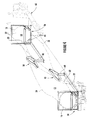
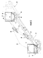
- FIGS 1 through 4 provide perspective views of a system 10 for arranging first and second wind turbine blades 12, 14 for transport and/or storage according to one embodiment of the present invention.
- Each wind turbine blade 12, 14 generally includes a blade root 16, 18 at one end and a blade tip 20, 22 at the opposite end.
- Each blade root 16, 18 is generally round in cross-section and includes bolts, screws, studs 24, or other structure known in the art for attaching a wind turbine blade to a rotor of a wind turbine.
- the wind turbine blades 12, 14 typically extend up to 80-120 feet, or more, and gradually curve from the blade root to the blade tip, creating a convex 26 surface on one side and a concave 28 surface on the opposite side.
- wind turbine blades 12, 14 may have a rounded leading edge 30 (i.e., the edge facing the direction of rotation) and a tapered trailing edge 32 (i.e., the edge facing away from the direction of rotation) that combine to give the wind turbine blades 12, 14 an aerodynamic or airfoil shape.
- Wind turbine blades often include additional internal structural support behind the leading edge 30 to facilitate transferring and transporting the relatively heavy and fragile wind turbine blades.
- each blade root 16, 18 is near or proximate to the blade tip 22, 20 of the opposite wind turbine blade, and each leading edge 30 is near or proximate to the trailing edge 32 of the opposite wind turbine blade.
- the wind turbine blades are nested so that the convex surface 26 of one wind turbine blade faces the concave surface 28 of the other wind turbine blade.
- the system 10 shown in Figures 1 through 4 generally includes first and second root cradles 34, 36 and first and second tip cradles 38, 40.
- the root cradles 34, 36 and tip cradles 38, 40 provide support and cushioning for the blade roots 16, 18 and blade tips 20, 22, respectively, during transport and/or storage.
- the first root cradle 34 and the first tip cradle 38 refer to the structures that support the first wind turbine blade 12
- the second root cradle 36 and the second tip cradle 40 refer to the structures that support the second wind turbine blade 14.
- the first and second root cradles 34, 36 are opposed to each other and are separated by a distance that may be approximately equal to the length of the wind turbine blades.
- the first tip cradle 38 is located closer to or proximate to the second root cradle 36 to support and cushion the blade tip 20 of the first wind turbine blade 12, and the second tip cradle 40 is located closer to or proximate to the first root cradle 34 to support and cushion the blade tip 22 of the second wind turbine blade 14.
- the root cradles 34, 36 and tip cradles 38, 40 generally include cushions 44 or pads that form a seating surface which conforms to the exterior surface of the blade root or blade tip.
- the cushions 44 or pads may be configured to completely or partially surround the blade roots 16, 18 and/or blade tips 20, 22.
- a strap, banding, or other suitable device may be used to hold the wind turbine blades 12, 14 in place.
- the first and second tip cradles 38, 40 may include complementary padded surfaces 46 shaped to conform to the shape of the wind turbine blades 12, 14.
- the complementary padded surfaces 46 define a first end 48 and a second end 50 in each tip cradle 38, 40.
- the first end 48 of each tip cradle 38, 40 is shaped to conform to and support the leading edge 30 of the wind turbine blades 12, 14.
- the second end 50 of each tip cradle 38, 40 is shaped to conform to and support the trailing edge of the wind turbine blades 12, 14.
- the second end 50 may include additional cushions 52 to further protect the trailing edge 32 of the wind turbine blades 12, 14, which is typically more delicate and prone to damage during transport and/or storage than the leading edges 30.
- the complementary padded surfaces 46 may further include a hinge 54 at the first end 48 and a hasp 56 or latch at the second end 50.
- the hinge 54 allows the complementary padded surfaces 46 to be pivotally separated or opened to receive a wind turbine blade. The complementary padded surfaces 46 may then be brought back together or closed and held in place by the hasp 56 or latch to hold the wind turbine blade in place.
- the first and second tip cradles 38, 40 may be rotatably or pivotally connected to a first and second support 58, 60, respectively.
- the first and/or second supports 58, 60 may be rotatably or pivotally connected to either or both of the first and/or second root cradles 34, 36.
- the first and second supports 58, 60 may be a stanchion, rod, pole, or similar structure known to one of ordinary skill in the art for supporting the weight of the blade tip of a wind turbine blade.
- a ratchet 62, gear, bearing, or similar structure between each tip cradle 38, 40 and the associated support 58, 60 allows each tip cradle 38, 40 to rotate or pivot about the respective support 58, 60.
- the first support 58 is typically closer to or proximate to the second root cradle 36
- the second support 60 is typically closer to or proximate to the first root cradle 34.
- the first and/or second supports 58, 60 may be structurally connected to either or both of the first and/or second root cradles 34, 36, as shown in Figures 1 through 4 .
- the first and second supports 58, 60 may be structurally separated from both the first and second root cradles 34, 36.
- the first and second supports 58, 60 may be attached to the spine or bed of a commercial carrier 68.
- wind turbine blades Due to the weight of wind turbine blades 12, 14 and the relative fragility of the trailing edge 32 of wind turbine blades, wind turbine blades are typically lifted and moved by cranes, hoists, or similar devices with the leading edge 30 down.
- the complementary padded surfaces 46 of the first tip cradle 38 may be opened, and the first wind turbine blade 12 may then be transferred proximate to the first root cradle 34 with the leading edge 30 down.
- the blade tip 20 may then be positioned in the first tip cradle 38, and the complementary padded surfaces 46 of the first tip cradle 38 may then be closed and held shut by the hasp 56.
- the first wind turbine blade 12 may then be rotated to the position shown in Figure 2 , with the first tip cradle 38 protecting and supporting the leading 30 and trailing 32 edges while the first wind turbine blade 12 is rotated.
- the complementary padded surfaces 46 of the first tip cradle 38 define a first support plane 64 angled approximately 20 to 90 degrees with respect to a horizontal line 65.
- the first support plane 64 may be angled approximately 30 to 80 degrees, 40 to 70 degrees, or 45 degrees with respect to the horizontal line 65.
- the first tip cradle 38 supports the first wind turbine blade 12 with the first end 48 of the first tip cradle 38 higher than the second end 50 of the first tip cradle 38.
- the complementary padded surfaces 46 of the second tip cradle 40 may be opened, and the second wind turbine blade 14 may then be transferred proximate to the second root cradle 36 with the leading edge 30 down.
- the blade tip 22 may then be positioned in the second tip cradle 40, and the complementary padded surfaces 46 of the second tip cradle 40 may then be closed and held shut by the hasp 56.
- the second wind turbine blade 14 may then be rotated, if necessary, to the position shown in Figure 3 , with the second tip cradle 40 protecting and supporting the leading 30 and trailing 32 edges while the second wind turbine blade 14 is rotated.
- the complementary surfaces 46 of the second tip cradle 40 define a second support plane 66 angled approximately 20 to 90 degrees with respect to the horizontal line 65.
- the second support plane 66 may be angled approximately 30 to 80 degrees, 40 to 70 degrees, or 45 degrees with respect to the horizontal line 65.
- the first tip cradle 38 may be at a higher elevation than the second tip cradle 40.
- This difference in elevation between the first and second tip cradles 38, 40 may be accomplished by a difference in length between the first and second supports 58, 60.
- the location of the pivotal connection between each tip cradle 38, 40 and its associated support 58, 60 may be adjusted to achieve the same difference in elevation between the first and second tip cradles 38, 40.
- the difference in elevation between the first and second tip cradles 38, 40 enhances the ability of the system 10 to nest the first and second wind turbine blades 12, 14 closer together to reduce the resulting width and height of the system 10 and wind turbine blades 12, 14.
- Figure 4 shows the system 10 with wind turbine blades 12, 14 loaded on the commercial carrier 68 for transport over public roads and/or storage.
- the first and second tip cradles 38, 40 and the first and second root cradles 34, 36 support the first and second wind turbine blades 12, 14 at an angle approximately 20 to 90 degrees with respect to the horizontal line 65.
- the first and second wind turbine blades 12, 14 may be angled approximately 30 to 80 degrees, 40 to 70 degrees, or 45 degrees with respect to the horizontal line 65.
- the system 10 arranges the first and second wind turbine blades 12, 14 to reduce width and height of the system 10 and wind turbine blades 12, 14 during transportation and/or storage.
- Figure 6 shows an end view of the system 10 (in phantom) and wind turbine blades 12, 14 shown in Figure 4 .
- a shipping area 70 for the system 10 and the wind turbine blades 12, 14 is defined as the maximum width and height of the outer perimeter of the system 10 and wind turbine blades 12, 14.
- the shipping area 70 is shown in Figure 6 as a dashed box circumscribing the outer perimeter of the system 10 and wind turbine blades 12, 14. With the first 12 and second 14 wind turbine blades arranged approximately diagonally by the system 10, the shipping area has a maximum width of 81 ⁇ 2 feet and a maximum height of 131 ⁇ 2 feet. It will be appreciated that the shipping area 70 defined by the system 10 and wind turbine blades 12, 14 may fit within or extend beyond the width and height of the commercial carrier 68. As a result, the system 10 arranges the wind turbine blades 12, 14 for transportation and/or storage without exceeding state and local transportation regulations regarding the maximum width and height of items transported on public roads.
Landscapes
- Engineering & Computer Science (AREA)
- Mechanical Engineering (AREA)
- Health & Medical Sciences (AREA)
- Public Health (AREA)
- Transportation (AREA)
- Life Sciences & Earth Sciences (AREA)
- Sustainable Development (AREA)
- Sustainable Energy (AREA)
- Chemical & Material Sciences (AREA)
- Combustion & Propulsion (AREA)
- General Engineering & Computer Science (AREA)
- Wind Motors (AREA)
Applications Claiming Priority (1)
| Application Number | Priority Date | Filing Date | Title |
|---|---|---|---|
| US12/632,199 US8177462B2 (en) | 2009-12-07 | 2009-12-07 | System and method for arranging wind turbine blades |
Publications (1)
| Publication Number | Publication Date |
|---|---|
| EP2330291A2 true EP2330291A2 (de) | 2011-06-08 |
Family
ID=43501149
Family Applications (1)
| Application Number | Title | Priority Date | Filing Date |
|---|---|---|---|
| EP10192152A Withdrawn EP2330291A2 (de) | 2009-12-07 | 2010-11-23 | System und Verfahren zur Anordnung von Windturbinenschaufeln |
Country Status (3)
| Country | Link |
|---|---|
| US (1) | US8177462B2 (de) |
| EP (1) | EP2330291A2 (de) |
| CN (1) | CN102086847A (de) |
Cited By (3)
| Publication number | Priority date | Publication date | Assignee | Title |
|---|---|---|---|---|
| DE102011113482A1 (de) | 2011-09-13 | 2013-03-14 | Nordex Energy Gmbh | Schutzeinrichtung für ein Rotorblatt einer Windenergieanlage |
| EP2669507A1 (de) * | 2012-06-01 | 2013-12-04 | Siemens Aktiengesellschaft | Transportieren und Stapeln von einander gegenüber und übereinander liegenden gebogenen Schaufeln |
| EP2912305B1 (de) | 2012-10-26 | 2021-03-03 | LM WP Patent Holding A/S | Verfahren und system zum transport und zur lagerung von mindestens zwei windturbinenschaufeln |
Families Citing this family (9)
| Publication number | Priority date | Publication date | Assignee | Title |
|---|---|---|---|---|
| NZ590008A (en) * | 2008-05-23 | 2012-06-29 | Siemens Ag | A mounting bracket device for mounting a blade of a wind turbine to a transport |
| DK3026258T3 (da) | 2010-08-12 | 2019-10-28 | Lm Wp Patent Holding As | Transport- og lagringssystem til vindmøllevinger |
| EP2487363A1 (de) * | 2011-01-31 | 2012-08-15 | Siemens Aktiengesellschaft | Hubsystem und Verfahren zum Heben von Rotorschaufeln von Windturbinen |
| US8602700B2 (en) * | 2012-02-16 | 2013-12-10 | General Electric Company | Shipping fixture and method for transporting rotor blades |
| EP3098435B1 (de) * | 2012-10-26 | 2025-01-29 | LM Wind Power A/S | Verfahren und system zum transport und zur lagerung von mindestens zwei windturbinenschaufeln |
| US10066606B2 (en) * | 2014-03-31 | 2018-09-04 | Vestas Wind Systems A/S | Stacking wind turbine blades for sea transport |
| EP3169893B1 (de) * | 2014-07-17 | 2021-01-13 | LM WP Patent Holding A/S | Modulares system für den transport von windturbinenschaufeln |
| CN109642546B (zh) * | 2016-09-02 | 2021-03-16 | Lm风力发电国际技术有限公司 | 用于风力涡轮机叶片的运输和存储系统 |
| EP4112927B1 (de) * | 2021-06-28 | 2024-04-03 | Siemens Gamesa Renewable Energy A/S | Handhabungsanordnung |
Family Cites Families (15)
| Publication number | Priority date | Publication date | Assignee | Title |
|---|---|---|---|---|
| US1996695A (en) * | 1933-05-09 | 1935-04-02 | Jr William J Bigley | Transportation method and means |
| US2335692A (en) | 1943-01-30 | 1943-11-30 | Thomas W Murray | Supporting table and jack |
| US2725241A (en) * | 1952-02-28 | 1955-11-29 | Jr Talbert A Leonard | Wing carrying device for transporting aircraft wings |
| US2808288A (en) | 1954-01-25 | 1957-10-01 | Spencer Safford Loadcraft Inc | Vehicle transportation and storage capsule |
| US4341494A (en) * | 1980-02-13 | 1982-07-27 | Norca Corporation | Variable-length reduced pivot for railway car |
| US4750785A (en) * | 1987-06-22 | 1988-06-14 | Helton Jesse D | Truss transportation trailer |
| US5683213A (en) | 1996-04-29 | 1997-11-04 | High Concrete Structures, Inc. | Loading fixture |
| GB0109515D0 (en) | 2001-04-17 | 2001-06-06 | Neg Micon As | A method for transporting a set of large longitudinal items, a package system to be used by the method and use of such a package system |
| DE10200401A1 (de) * | 2002-01-08 | 2003-07-24 | Aloys Wobben | Vorrichtung zum Handhaben von Stückgütern |
| US20030175089A1 (en) | 2002-03-13 | 2003-09-18 | Preben Almind | Transport container for wind turbine blades |
| DK177128B1 (da) | 2003-07-10 | 2011-12-19 | Lm Glasfiber As | Transport og opbevaring af forkrumme vindmøllevinger |
| DK176923B1 (da) * | 2004-06-29 | 2010-05-17 | Vamdrup Specialtransp Aps | Fremgangsmåde til transport af en lang vindmøllevinge samt et køretøj til transport heraf |
| US20070177954A1 (en) * | 2006-01-31 | 2007-08-02 | General Electric Company | Method and apparatus for containing and/or transporting rotor blades |
| US7713007B2 (en) | 2007-05-31 | 2010-05-11 | General Electric Company | Method and apparatus for containing, storing and/or transporting curved wind turbine rotor blades |
| US7967536B2 (en) | 2008-05-02 | 2011-06-28 | Gamesa Innovation & Technology, S.L. | Blade transportation |
-
2009
- 2009-12-07 US US12/632,199 patent/US8177462B2/en not_active Expired - Fee Related
-
2010
- 2010-11-23 EP EP10192152A patent/EP2330291A2/de not_active Withdrawn
- 2010-12-07 CN CN201010592421XA patent/CN102086847A/zh active Pending
Non-Patent Citations (1)
| Title |
|---|
| None |
Cited By (5)
| Publication number | Priority date | Publication date | Assignee | Title |
|---|---|---|---|---|
| DE102011113482A1 (de) | 2011-09-13 | 2013-03-14 | Nordex Energy Gmbh | Schutzeinrichtung für ein Rotorblatt einer Windenergieanlage |
| EP2570654A2 (de) | 2011-09-13 | 2013-03-20 | Nordex Energy GmbH | Schutzeinrichtung für ein Rotorblatt einer Windenergieanlage |
| DE102011113482B4 (de) * | 2011-09-13 | 2013-04-18 | Nordex Energy Gmbh | Schutzeinrichtung für ein Rotorblatt einer Windenergieanlage |
| EP2669507A1 (de) * | 2012-06-01 | 2013-12-04 | Siemens Aktiengesellschaft | Transportieren und Stapeln von einander gegenüber und übereinander liegenden gebogenen Schaufeln |
| EP2912305B1 (de) | 2012-10-26 | 2021-03-03 | LM WP Patent Holding A/S | Verfahren und system zum transport und zur lagerung von mindestens zwei windturbinenschaufeln |
Also Published As
| Publication number | Publication date |
|---|---|
| US20110135417A1 (en) | 2011-06-09 |
| US8177462B2 (en) | 2012-05-15 |
| CN102086847A (zh) | 2011-06-08 |
Similar Documents
| Publication | Publication Date | Title |
|---|---|---|
| US8177462B2 (en) | System and method for arranging wind turbine blades | |
| US8511921B2 (en) | System and method for arranging wind turbine blades | |
| CN106536919B (zh) | 用于运输风力涡轮机叶片的模块系统 | |
| US10781834B2 (en) | Method and system for transporting and storing at least two wind turbine blades | |
| US8562302B2 (en) | Wind turbine blade with integrated handling mechanism attachment bores | |
| US7713007B2 (en) | Method and apparatus for containing, storing and/or transporting curved wind turbine rotor blades | |
| EP2411300B1 (de) | Verpackungsverfahren und system für drei windgeneratorschaufeln | |
| CN100540887C (zh) | 用于运输风力涡轮机转子叶片的包装装置 | |
| EP2239459A2 (de) | Transportsystem zum Transport eines Holms | |
| US20070177954A1 (en) | Method and apparatus for containing and/or transporting rotor blades | |
| CN107667223B (zh) | 用于风力涡轮机转子叶片的模块化运输和存储系统 | |
| BR102014009598A2 (pt) | Arranjo de suporte de pá de turbina eólica e método de manipular um número de pás de turbinas eólicas | |
| US9168858B2 (en) | Two or three wind turbine blades as one unit | |
| CN204197598U (zh) | 一种夹板式风电叶片运输支架 | |
| CN113446165A (zh) | 风力涡轮机部件运输装置 |
Legal Events
| Date | Code | Title | Description |
|---|---|---|---|
| PUAI | Public reference made under article 153(3) epc to a published international application that has entered the european phase |
Free format text: ORIGINAL CODE: 0009012 |
|
| AK | Designated contracting states |
Kind code of ref document: A2 Designated state(s): AL AT BE BG CH CY CZ DE DK EE ES FI FR GB GR HR HU IE IS IT LI LT LU LV MC MK MT NL NO PL PT RO RS SE SI SK SM TR |
|
| AX | Request for extension of the european patent |
Extension state: BA ME |
|
| STAA | Information on the status of an ep patent application or granted ep patent |
Free format text: STATUS: THE APPLICATION IS DEEMED TO BE WITHDRAWN |
|
| 18D | Application deemed to be withdrawn |
Effective date: 20130601 |
|
| P01 | Opt-out of the competence of the unified patent court (upc) registered |
Effective date: 20230522 |