EP2330045A2 - Container with height-adjustable base - Google Patents
Container with height-adjustable base Download PDFInfo
- Publication number
- EP2330045A2 EP2330045A2 EP10015324A EP10015324A EP2330045A2 EP 2330045 A2 EP2330045 A2 EP 2330045A2 EP 10015324 A EP10015324 A EP 10015324A EP 10015324 A EP10015324 A EP 10015324A EP 2330045 A2 EP2330045 A2 EP 2330045A2
- Authority
- EP
- European Patent Office
- Prior art keywords
- spindle
- container
- container according
- spindles
- drive
- Prior art date
- Legal status (The legal status is an assumption and is not a legal conclusion. Google has not performed a legal analysis and makes no representation as to the accuracy of the status listed.)
- Withdrawn
Links
Images

Classifications
-
- B—PERFORMING OPERATIONS; TRANSPORTING
- B65—CONVEYING; PACKING; STORING; HANDLING THIN OR FILAMENTARY MATERIAL
- B65D—CONTAINERS FOR STORAGE OR TRANSPORT OF ARTICLES OR MATERIALS, e.g. BAGS, BARRELS, BOTTLES, BOXES, CANS, CARTONS, CRATES, DRUMS, JARS, TANKS, HOPPERS, FORWARDING CONTAINERS; ACCESSORIES, CLOSURES, OR FITTINGS THEREFOR; PACKAGING ELEMENTS; PACKAGES
- B65D83/00—Containers or packages with special means for dispensing contents
- B65D83/0005—Containers or packages provided with a piston or with a movable bottom or partition having approximately the same section as the container
- B65D83/0011—Containers or packages provided with a piston or with a movable bottom or partition having approximately the same section as the container moved by a screw-shaft
-
- B—PERFORMING OPERATIONS; TRANSPORTING
- B65—CONVEYING; PACKING; STORING; HANDLING THIN OR FILAMENTARY MATERIAL
- B65D—CONTAINERS FOR STORAGE OR TRANSPORT OF ARTICLES OR MATERIALS, e.g. BAGS, BARRELS, BOTTLES, BOXES, CANS, CARTONS, CRATES, DRUMS, JARS, TANKS, HOPPERS, FORWARDING CONTAINERS; ACCESSORIES, CLOSURES, OR FITTINGS THEREFOR; PACKAGING ELEMENTS; PACKAGES
- B65D21/00—Nestable, stackable or joinable containers; Containers of variable capacity
- B65D21/08—Containers of variable capacity
-
- B—PERFORMING OPERATIONS; TRANSPORTING
- B65—CONVEYING; PACKING; STORING; HANDLING THIN OR FILAMENTARY MATERIAL
- B65G—TRANSPORT OR STORAGE DEVICES, e.g. CONVEYORS FOR LOADING OR TIPPING, SHOP CONVEYOR SYSTEMS OR PNEUMATIC TUBE CONVEYORS
- B65G1/00—Storing articles, individually or in orderly arrangement, in warehouses or magazines
- B65G1/02—Storage devices
- B65G1/04—Storage devices mechanical
- B65G1/06—Storage devices mechanical with means for presenting articles for removal at predetermined position or level
- B65G1/07—Storage devices mechanical with means for presenting articles for removal at predetermined position or level the upper article of a pile being always presented at the same predetermined level
Definitions
- the invention relates to a container with height adjustable bottom.
- Such containers are for example from the DE 10 2004 048 428 A1 known. They serve, in particular, always to present merchandise in a readily visible and easily removable manner by raising the container bottom with increasing emptying of the container. To adjust the height of the floor, for example, serve motor-driven scissor lift or pneumatic cushion.
- the invention has for its object to provide a new container with height adjustable bottom, which allows a more accurate, smoother adjustment of the ground level than the known such containers.
- the task of this solution container according to the invention is characterized by at least one spindle with a spindle nut and a drive for rotating the spindle or spindle nut, wherein the spindle nut or the spindle moves the container bottom translating by adjusting its height.
- Such a lifting device which is based on a spindle and a spindle nut, allows the container bottom to be displaced exactly vertically without jamming. While it would be possible to rotate the spindle nut for its translational displacement on an axially fixed spindle or to move the container bottom with a fixed spindle nut under axial displacement of the rotated spindle by the spindle itself, in a preferred embodiment of the invention, the drive for rotation the spindle and the spindle nut displaced on the spindle provided for translational movement of the container bottom.
- the container a plurality of spindles, each with a spindle nut and the drive comprises a drive train for common rotation of the spindles or spindle nuts.
- each spindle could be assigned a separate drive motor, the drive motors being synchronized with one another.
- the preferably endless drive train may be e.g. to act a chain or a toothed belt, which engages or on a coaxial to the spindle chain or gear. This means that all spindles or spindle nuts can be rotated exactly synchronously thanks to the common drive train.
- the spindles are arranged on the edge of the container bottom and in particular in each case in a corner region of the container bottom, so that they do not protrude disturbingly into the container space.
- the spindles are mounted at its lower end easily rotatable about the spindle axis.
- the spindles at their lower end on a rounding or tip, which ensures a smooth rotation.
- the spindle nuts may be rigidly or rotatably connected to the container bottom.
- the container bottom can only rest on the spindle nuts.
- the container bottom comprises, for example, two carriers, which preferably intersect.
- Such a container bottom can be made extremely stable, which contributes to the tilt-free height adjustment of the soil.
- the spindle nuts are connected to ends of the carrier.
- the spindles are suitably guided by at least one coaxial spindle guide, wherein such spindle guides can be mounted next to the spindle nuts at the ends of the carrier.
- a bearing member for supporting the spindles, may be provided near its upper end and bearing members near its lower end, with a drive wheel, preferably sprocket, meshing with the drive train for commonly rotating the spindles between the bearing members near the lower end End is arranged.
- the arrangement of the drive wheel between the close-lying bearing elements gives the spindle drive a high, its proper function ensuring dimensional stability.
- a gear preferably a sprocket, for the rotary drive of the relevant spindle by a motor / gear unit.
- the arrangement of this gear between the close-lying bearing elements ensures a high dimensional stability.
- the bearing elements arranged near the lower spindle element are expediently arranged on an extension piece coupled to the remaining spindle. This measure allows a convenient installation of the relevant drive elements.
- a gear for rotating the relevant spindle can be provided manually or with the aid of an engageable rotary drive.
- a transmission which is preferably designed as a worm gear with a rotatable by hand or by the rotary drive worm drive shaft can be used as an alternative to the aforementioned drive.
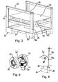
- a cuboid container has vertical side walls 1 to 4 and a container bottom 5.
- the container bottom 5 comprises, in addition to a continuous bottom wall 8, two intersecting supports 6 and 7 arranged below the bottom wall.
- a vertical spindle 9 is arranged with a spindle nut 10 rotatable on the spindle.
- the four spindle nuts 10 are each rigidly connected to one end of the respective carrier 6 and 7.
- Above the spindle nuts 10 each have a spindle guide 11 is provided, which is also rigidly connected to the respective carrier end.
- the chain 13 is engaged with a drive sprocket 14 of an electric motor / gear unit 15.
- each have a further spindle guide 16 is formed below the sprockets 9 .
- the lower, rounded end of the spindles 9 is seated in each case on a bearing block 17.
- the motor / gear unit 15, the four spindle guides 16 and the four bearing blocks 17 are mounted on a support frame of the container (not shown) arranged below the container bottom 15.
- the spindles 9 each have at their upper end face a recess 18, e.g. with a hexagonal or square cross section for engagement of a turning tool.
- the motor / gear unit 15 can be put into operation or one of the spindles 9 are rotated by hand. In both cases, a synchronous rotation of all four sprockets 12 through the chain 13. This results in a uniform displacement of the four spindle nuts 10 on the spindles 9 and thus one, at all four corners even and tilt-free raising or lowering of the container bottom 5.
- the Intersecting beams 6 and 7 give the container bottom a high stability, which additionally promotes a tilt-free, smooth vertical movement of the container bottom 5 together with the spindle guides 11,16.
- FIG. 3 shown container with a bottom 5a is formed like a frame with open side walls.
- Two of the side walls consist only of vertical frame members 19 and 20 and horizontal frame members 21 and 22.
- At the other two sides of the container upper horizontal frame parts are missing, so that from these sides a loaded on the container height addition range 23 is inserted into the container and on the Floor 5a can be discontinued.
- the side walls could be convertible around horizontal axes.
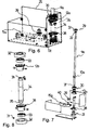
- the horizontal frame parts 21,22 are formed by a box profile, while the vertical frame parts each have a U-profile with different lengths U-legs.
- each foot part 24 is attached in the form of an open-topped box.
- Outwardly facing side walls 25 and 26 of the foot parts protrude in height beyond the remaining side walls and form tabs for fastening on the outside on a base frame formed by the frame parts 21 and two further frame parts 27.
- bearing elements 29 to 31 are respectively provided, wherein the bearing elements 29 are arranged near the upper end of the spindle and the bearing elements 30,31 near the lower end of the spindle.
- the bearing elements 29 to 31 each consist of a retaining ring 32 with a seat for receiving a ball bearing 33rd
- the spindle 9a comprises a thread-free extension piece 34 which engages with a coaxial with the spindle axis end pin 35 in the ball bearing 33 of the lowermost bearing element 31.
- a coaxial with the spindle axis Stirneinsenkung 36 is provided for the engagement of an end pin 37 at the lower end of the upper spindle part.
- the extension piece 34 carries near its upper end below the bearing member 30 a first sprocket 12a and near its lower end above the bearing member 31 a second sprocket 38.
- the sprockets 12a of all four spindles are interconnected by a circumferential chain (not shown).
- the sprocket 38 of one of the four spindles is connected via a chain (not shown) in connection with a sprocket 39, which sits on a drive pin 40 of a motor / gear unit 15a.
- gear 41 is arranged coaxially with the spindle axis on one of the four spindles 9a at its upper end above the bearing element 29 in question.
- the gear 41 is engaged with a worm drive shaft 42 which is axially fixed at its ends by pivot members 43 and 44.
- the pivot bearing elements can be secured at 46 within the vertical and / or horizontal frame members 19,20,22 by screws.
- Via an end-side engagement opening 45, the shaft 42 for example by means of a tool, possibly electromechanical tool, rotatable.
- the corresponding spindle 9a can be set in rotation via the said chain drive comprising the sprockets 38 and 39. Via the sprocket 12a and the chain (not shown) this rotation is also transmitted to the remaining three spindles.
- the spindle nuts 10a move smoothly up or down. Accordingly, the bottom 5a raises or lowers.
- the bearing elements 29 to 31 are connected via their retaining ring 32 with the relevant frame parts or the bottom of the foot part 24. According stable, the spindles 9a are stored. The entire drive remains dimensionally stable.
- the bottom 5a can also be adjusted via the worm drive comprising the gear 41 and the worm shaft 42, by hand or with the aid of a power tool.
Landscapes
- Engineering & Computer Science (AREA)
- Mechanical Engineering (AREA)
- Cultivation Receptacles Or Flower-Pots, Or Pots For Seedlings (AREA)
- Warehouses Or Storage Devices (AREA)
- Food-Manufacturing Devices (AREA)
- Filling Of Jars Or Cans And Processes For Cleaning And Sealing Jars (AREA)
Abstract
Description
Die Erfindung betrifft einen Behälter mit höhenverstellbarem Boden.The invention relates to a container with height adjustable bottom.
Derartige Behälter sind beispielsweise aus der
Bei solchen Behältern besteht das Problem, den möglichst nahe an die vertikalen Seitenwände heranreichenden Behälterboden exakt vertikal und dadurch verkantungsfrei anheben bzw. absenken zu können.In such containers, there is the problem of being able to raise or lower the container bottom, which is as close as possible to the vertical side walls, exactly vertically and thus free from jamming.
Der Erfindung liegt die Aufgabe zugrunde, einen neuen Behälter mit höhenverstellbarem Boden zu schaffen, der eine exaktere, problemlosere Verstellung der Bodenhöhe als die bekannten derartigen Behälter ermöglicht.The invention has for its object to provide a new container with height adjustable bottom, which allows a more accurate, smoother adjustment of the ground level than the known such containers.
Der diese Aufgabe lösende Behälter nach der Erfindung ist gekennzeichnet durch wenigstens eine Spindel mit einer Spindelmutter und einem Antrieb zur Drehung der Spindel oder Spindelmutter, wobei die Spindelmutter oder die Spindel den Behälterboden unter Verstellung seiner Höhe translatorisch bewegt.The task of this solution container according to the invention is characterized by at least one spindle with a spindle nut and a drive for rotating the spindle or spindle nut, wherein the spindle nut or the spindle moves the container bottom translating by adjusting its height.
Durch eine solche, auf einer Spindel und einer Spindelmutter basierenden Hebeeinrichtung lässt sich der Behälterboden exakt vertikal verkantungsfrei verschieben. Während es möglich wäre, die Spindelmutter zu ihrer translatorischen Verschiebung auf einer in axialer Richtung feststehenden Spindel zu drehen oder den Behälterboden bei feststehender Spindelmutter unter axialer Verschiebung der gedrehten Spindel durch die Spindel selbst zu verschieben, ist in einer bevorzugten Ausführungsform der Erfindung der Antrieb zur Drehung der Spindel und die auf der Spindel verschobene Spindelmutter zur translatorischen Bewegung des Behälterbodens vorgesehen.Such a lifting device, which is based on a spindle and a spindle nut, allows the container bottom to be displaced exactly vertically without jamming. While it would be possible to rotate the spindle nut for its translational displacement on an axially fixed spindle or to move the container bottom with a fixed spindle nut under axial displacement of the rotated spindle by the spindle itself, in a preferred embodiment of the invention, the drive for rotation the spindle and the spindle nut displaced on the spindle provided for translational movement of the container bottom.
Während im einfachsten Fall eine einzige, z.B. zu einem runden Behälterboden koaxiale Spindel, die in den Behälterraum hineinragt, zur Verstellung des Behälterbodens genügen kann, weist in der bevorzugten Ausführungsform der Erfindung der Behälter mehrere Spindeln mit je einer Spindelmutter auf und der Antrieb umfasst einen Antriebsstrang zur gemeinsamen Drehung der Spindeln oder Spindelmuttern. Alternativ zu einem Antriebsstrang zur gemeinsamen Drehung könnte jeder Spindel ein gesonderter Antriebsmotor zugeordnet sein, wobei die Antriebsmotoren untereinander synchronisiert sind.While in the simplest case a single, e.g. to a round container bottom coaxial spindle, which projects into the container space, may be sufficient for adjusting the container bottom, has in the preferred embodiment of the invention, the container a plurality of spindles, each with a spindle nut and the drive comprises a drive train for common rotation of the spindles or spindle nuts. As an alternative to a drive train for common rotation, each spindle could be assigned a separate drive motor, the drive motors being synchronized with one another.
Bei dem vorzugsweise endlosen Antriebsstrang kann es sich z.B. um eine Kette oder einen Zahnriemen handeln, die bzw. der an einem zur Spindel koaxialen Ketten- bzw. Zahnrad angreift. So lassen sich durch den gemeinsamen Antriebsstrang alle Spindeln oder Spindelmuttern exakt synchron drehen.The preferably endless drive train may be e.g. to act a chain or a toothed belt, which engages or on a coaxial to the spindle chain or gear. This means that all spindles or spindle nuts can be rotated exactly synchronously thanks to the common drive train.
Vorzugsweise sind die Spindeln am Rand des Behälterbodens und insbesondere jeweils in einem Eckenbereich des Behälterbodens angeordnet, so dass sie nicht störend in den Behälterraum hineinragen. Zweckmäßig sind die Spindeln an ihrem unteren Ende leichtgängig um die Spindelachse drehbar gelagert. Insbesondere weisen die Spindeln an ihrem unteren Ende eine Rundung oder Spitze auf, die eine leichtgängige Drehung sichert.Preferably, the spindles are arranged on the edge of the container bottom and in particular in each case in a corner region of the container bottom, so that they do not protrude disturbingly into the container space. Appropriately, the spindles are mounted at its lower end easily rotatable about the spindle axis. In particular, the spindles at their lower end on a rounding or tip, which ensures a smooth rotation.
In weiterer Ausgestaltung der Erfindung können die Spindelmuttern starr oder drehbeweglich mit dem Behälterboden verbunden sein. In einer Ausführungsform kann der Behälterboden auf den Spindelmuttern nur aufliegen.In a further embodiment of the invention, the spindle nuts may be rigidly or rotatably connected to the container bottom. In one embodiment, the container bottom can only rest on the spindle nuts.
In einer Ausführungsform der Erfindung umfasst der Behälterboden z.B. zwei Träger, die sich vorzugsweise kreuzen. Ein solcher Behälterboden kann außerordentlich stabil ausgebildet sein, was zur verkantungsfreien Höhenverstellung des Bodens beiträgt.In one embodiment of the invention, the container bottom comprises, for example, two carriers, which preferably intersect. Such a container bottom can be made extremely stable, which contributes to the tilt-free height adjustment of the soil.
Zweckmäßig sind die Spindelmuttern mit Enden der Träger verbunden.Suitably, the spindle nuts are connected to ends of the carrier.
Die Spindeln sind zweckmäßig durch wenigstens eine koaxiale Spindelführung geführt, wobei solche Spindelführungen neben den Spindelmuttern an den Enden der Träger angebracht sein können.The spindles are suitably guided by at least one coaxial spindle guide, wherein such spindle guides can be mounted next to the spindle nuts at the ends of the carrier.
In einer weiteren Ausführungsform der Erfindung können zur Lagerung der Spindeln ein Lagerelement nahe ihrem oberen Ende und Lagerelemente nahe ihrem unteren Ende vorgesehen sein, wobei ein mit dem Antriebsstrang zur gemeinsamen Drehung der Spindeln im Eingriff stehendes Antriebsrad, vorzugsweise Kettenrad, zwischen den Lagerelementen nahe dem unteren Ende angeordnet ist. Die Anordnung des Antriebsrads zwischen den nahe beieinander liegenden Lagerelementen verleiht dem Spindelantrieb eine hohe, dessen einwandfreie Funktion sichernde Formstabilität.In another embodiment of the invention, for supporting the spindles, a bearing member may be provided near its upper end and bearing members near its lower end, with a drive wheel, preferably sprocket, meshing with the drive train for commonly rotating the spindles between the bearing members near the lower end End is arranged. The arrangement of the drive wheel between the close-lying bearing elements gives the spindle drive a high, its proper function ensuring dimensional stability.
Zwischen den Lagerelementen nahe dem unteren Ende von wenigstens einer der Spindeln kann ferner ein Zahnrad, vorzugsweise ein Kettenrad, für den Drehantrieb der betreffenden Spindel durch eine Motor-/Getriebeeinheit vorgesehen sein. Auch die Anordnung dieses Zahnrades zwischen den nahe beieinander liegenden Lagerelementen sichert eine hohe Formstabilität.Between the bearing elements near the lower end of at least one of the spindles may also be provided a gear, preferably a sprocket, for the rotary drive of the relevant spindle by a motor / gear unit. The arrangement of this gear between the close-lying bearing elements ensures a high dimensional stability.
Zweckmäßig sind die nahe dem unteren Spindelelement angeordneten Lagerelemente auf einem an die übrige Spindel angekoppelten Verlängerungsstück angeordnet. Diese Maßnahme erlaubt eine bequeme Montage der betreffenden Antriebselemente.The bearing elements arranged near the lower spindle element are expediently arranged on an extension piece coupled to the remaining spindle. This measure allows a convenient installation of the relevant drive elements.
Nahe dem oberen Ende von wenigstens einer der Spindeln kann ein Getriebe zur Drehung der betreffenden Spindel manuell oder mit Hilfe eines ankoppelbaren Drehantriebs vorgesehen sein. Ein solches Getriebe, das vorzugsweise als Schneckengetriebe mit einer von Hand oder durch den Drehantrieb drehbaren Schneckenantriebswelle ausgebildet ist, kann alternativ zu dem vorangehend genannten Antrieb eingesetzt werden.Near the upper end of at least one of the spindles, a gear for rotating the relevant spindle can be provided manually or with the aid of an engageable rotary drive. Such a transmission, which is preferably designed as a worm gear with a rotatable by hand or by the rotary drive worm drive shaft can be used as an alternative to the aforementioned drive.
Die Erfindung wird nachfolgend anhand eines Ausführungsbeispiels und der beiliegenden, sich auf dieses Ausführungsbeispiel beziehenden Zeichnungen weiter erläutert. Es zeigen:
- Fig. 1
- eine Schemadarstellung eines erfindungsgemäßen Behälters in einer Drauf- sicht,
- Fig. 2
- eine Detailansicht des Behälters von
Fig. 1 , die einen unteren Eckenbereich erfasst, - Fig. 3
- ein weiteres Ausführungsbeispiel für einen erfindungsgemäßen Behälter,
- Fig. 4
- einen unteren Eckenbereich des Behälters von
Fig. 3 mit einer Spindel, - Fig. 5
- ein zur Anordnung am oberen Ende der Spindel von
Fig. 2 vorgesehenes Schneckengetriebe, - Fig. 6
- den in
Fig. 5 gezeigten unteren Eckenbereich in vergrößerter Darstellung, - Fig. 7
- den unteren Eckenbereich mit der Spindel von
Fig. 4 in einer Explosions- darstellung, und - Fig. 8
- eine Detaildarstellung der Ansicht von
Fig. 7 .
- Fig. 1
- a schematic representation of a container according to the invention in a plan view,
- Fig. 2
- a detailed view of the container of
Fig. 1 that captures a lower corner area, - Fig. 3
- a further embodiment of a container according to the invention,
- Fig. 4
- a lower corner portion of the container of
Fig. 3 with a spindle, - Fig. 5
- a to the arrangement at the upper end of the spindle of
Fig. 2 provided worm gear, - Fig. 6
- the in
Fig. 5 shown lower corner area in an enlarged view, - Fig. 7
- the lower corner area with the spindle of
Fig. 4 in an exploded view, and - Fig. 8
- a detailed view of the view from
Fig. 7 ,
Ein quaderförmiger Behälter weist vertikale Seitenwände 1 bis 4 und einen Behälterboden 5 auf. Der Behälterboden 5 umfasst in dem gezeigten Ausführungsbeispiel neben einer durchgehenden Bodenwand 8 zwei sich kreuzende, unter der Bodenwand angeordnete Träger 6 und 7.A cuboid container has vertical side walls 1 to 4 and a
In den vier Eckenbereichen des Behälters ist jeweils eine vertikale Spindel 9 mit einer auf der Spindel drehbaren Spindelmutter 10 angeordnet. Die vier Spindelmuttern 10 sind jeweils starr mit einem Ende der betreffenden Träger 6 und 7 verbunden. Oberhalb der Spindelmuttern 10 ist jeweils eine Spindelführung 11 vorgesehen, die ebenfalls starr mit dem jeweiligen Trägerende verbunden ist.In the four corner regions of the container in each case a
Unterhalb des Behälterbodens 5 weist jede der Spindeln 9 ein zur Spindeldrehachse koaxiales Kettenrad 12 auf. Alle vier Kettenräder 12 verbindet ein endloser, in dem betreffenden Ausführungsbeispiel durch eine Kette 13 gebildeter Antriebsstrang. Die Kette 13 steht im Eingriff mit einem Antriebskettenrad 14 einer elektrischen Motor-/ Getriebeeinheit 15.Below the
Unterhalb der Kettenräder 9 ist jeweils eine weitere Spindelführung 16 gebildet. Das untere, abgerundete Ende der Spindeln 9 sitzt jeweils auf einem Lagerblock 17 auf. Die Motor-/Getriebeeinheit 15, die vier Spindelführungen 16 und die vier Lagerblöcke 17 sind an einem unterhalb des Behälterbodens 15 angeordneten Trägergestell des Behälters (nicht gezeigt) angebracht.Below the
Die Spindeln 9 weisen an ihrer oberen Stirnfläche jeweils eine Einsenkung 18 z.B. mit einem Sechs- oder Vierkantquerschnitt für den Eingriff eines Drehwerkzeugs auf.The
Zur Verstellung der Höhe des Behälterbodens 5 kann die Motor-/Getriebeeinheit 15 in Betrieb genommen oder eine der Spindeln 9 von Hand gedreht werden. In beiden Fällen erfolgt synchron eine Drehung aller vier Kettenräder 12 durch die Kette 13. Hierdurch ergibt sich eine gleichmäßige Verschiebung der vier Spindelmuttern 10 auf den Spindeln 9 und damit eine, an allen vier Ecken gleichmäßige und verkantungsfreie Anhebung oder Absenkung des Behälterbodens 5. Die sich kreuzenden Träger 6 und 7 verleihen dem Behälterboden eine hohe Stabilität, die zusätzlich zusammen mit den Spindelführungen 11,16 eine verkantungsfreie, leichtgängige Vertikalbewegung des Behälterbodens 5 fördert.To adjust the height of the
Ein in
Die horizontalen Rahmenteile 21,22 sind durch ein Kastenprofil gebildet, während die vertikalen Rahmenteile jeweils ein U-Profil mit unterschiedlich langen U-Schenkeln aufweisen.The
An den unteren vier Behälterecken ist jeweils ein Fußteil 24 in Form eines nach oben offenen Kastens angebracht. Nach außen weisende Seitenwände 25 und 26 der Fußteile ragen in der Höhe über die übrigen Seitenwände hinaus und bilden Laschen zur außenseitigen Befestigung an einem durch die Rahmenteile 21 und zwei weitere Rahmenteile 27 gebildeten Grundrahmen.At the bottom four container corners each
Innerhalb der vertikalen Rahmenschenkel 19,20 erstreckt sich jeweils eine Spindel 9a, auf der eine durch Drehung der Spindel vertikal bewegbare Spindelmutter 10α sitzt. Wie
Zur Halterung und drehbaren Lagerung der Spindel 9a sind jeweils drei Lagerelemente 29 bis 31 vorgesehen, wobei die Lagerelemente 29 nahe dem oberen Ende der Spindel und die Lagerelemente 30,31 nahe dem unteren Spindelende angeordnet sind. Die Lagerelemente 29 bis 31 bestehen aus je einem Haltering 32 mit einem Sitz für die Aufnahme eines Kugellagers 33.For mounting and rotatable mounting of the
Die Spindel 9a umfasst ein gewindefreier Verlängerungsstück 34, das mit einem zur Spindelachse koaxialen Endzapfen 35 in das Kugellager 33 des untersten Lagerelements 31 eingreift. Am oberen Ende des Verlängerungsstücks ist eine zur Spindelachse koaxiale Stirneinsenkung 36 für den Eingriff eines Endzapfens 37 am unteren Ende des oberen Spindelteils vorgesehen.The
Das Verlängerungsstück 34 trägt nahe seinem oberen Ende unterhalb des Lagerelements 30 ein erstes Kettenrad 12a und nahe seinem unteren Ende über dem Lagerelement 31 ein zweites Kettenrad 38. Die Kettenräder 12a aller vier Spindeln sind über eine (nicht gezeigte) umlaufende Kette miteinander verbunden. Das Kettenrad 38 von einer der vier Spindeln steht über eine (nicht gezeigte) Kette in Verbindung mit einem Kettenrad 39, das auf einem Antriebszapfen 40 einer Motor-/ Getriebeeinheit 15a sitzt.The
Ein in
Durch die Motor-/Getriebeeinheit 15a lässt sich über den genannten, die Kettenräder 38 und 39 umfassenden Kettenantrieb die entsprechende Spindel 9a in Drehung versetzen. Über das Kettenrad 12a und die (nicht gezeigte) Kette wird diese Drehung auch auf die übrigen drei Spindeln übertragen. Die Spindelmuttern 10a bewegen sich gleichmäßig nach oben oder unten. Entsprechend hebt oder senkt sich der Boden 5a.By means of the motor /
Die Lagerelemente 29 bis 31 sind über ihren Haltering 32 mit den betreffenden Rahmenteilen bzw. dem Boden des Fußteils 24 verbunden. Entsprechend stabil sind die Spindeln 9a gelagert. Der gesamte Antrieb bleibt formstabil.The bearing
Der Boden 5a lässt sich ferner über den das Zahnrad 41 und die Schneckenwelle 42 umfassenden Schneckenantrieb verstellen, von Hand oder mit Hilfe eines Elektrowerkzeugs.The bottom 5a can also be adjusted via the worm drive comprising the
Claims (15)
gekennzeichnet durch wenigstens eine Spindel (9) mit einer Spindelmutter (10) und einem Antrieb (12-15, 18) zur Drehung der Spindel (9) oder Spindelmutter, wobei die Spindelmutter (10) oder Spindel den Behälterboden (5) unter Verstellung seiner Höhe translatorisch bewegt.Container with height adjustable bottom (5),
characterized by at least one spindle (9) with a spindle nut (10) and a drive (12-15, 18) for rotating the spindle (9) or spindle nut, wherein the spindle nut (10) or spindle the container bottom (5) by adjusting its Height translationally moved.
dadurch gekennzeichnet,
dass der Antrieb (12-15, 18) zur Drehung der Spindel (9) und die Spindelmutter (10) zur translatorischen Bewegung des Behälterbodens (5) vorgesehen ist.Container according to claim 1,
characterized,
in that the drive (12-15, 18) for rotating the spindle (9) and the spindle nut (10) for translational movement of the container bottom (5) are provided.
dadurch gekennzeichnet,
dass mehrere Spindeln (9) mit je einer Spindelmutter (10) vorgesehen sind und der Antrieb (12-15, 18) einen Antriebsstrang (13) zur gemeinsamen Drehung der Spindeln (9) oder Spindelmuttern umfasst.Container according to claim 1 or 2,
characterized,
in that a plurality of spindles (9) each having a spindle nut (10) are provided and the drive (12-15, 18) comprises a drive train (13) for common rotation of the spindles (9) or spindle nuts.
dadurch gekennzeichnet,
dass der, vorzugsweise endlose, Antriebsstrang eine Kette (13) oder einen Zahnriemen umfasst.Container according to claim 3,
characterized,
in that the, preferably endless, drive train comprises a chain (13) or a toothed belt.
dadurch gekennzeichnet,
dass die Spindeln (9) am Rand des Behälterbodens (5) und insbesondere jeweils in einem Eckenbereich des Behälters angeordnet sind.Container according to claim 3 or 4,
characterized,
that the spindles (9) are arranged at the edge of the container bottom (5) and in particular in each case in a corner region of the container.
dadurch gekennzeichnet,
dass die Spindeln (9) an ihrem unteren Ende um die Spindelachse drehbar gelagert sind.Container according to one of claims 3 to 5,
characterized,
that the spindles (9) are rotatably mounted at its lower end about the spindle axis.
dadurch gekennzeichnet,
dass die Spindelmutter starr oder drehbeweglich mit dem Behälterboden (5) verbunden ist.Container according to one of claims 1 to 6,
characterized,
that the spindle nut is rigidly or rotatably connected to the container bottom (5).
dadurch gekennzeichnet,
dass der Behälterboden (5) eine durchgehende Bodenwand (8) abstützende Träger (6,7) umfasst, die sich vorzugsweise kreuzen.Container according to one of claims 1 to 7,
characterized,
in that the container bottom (5) comprises a carrier (6, 7) supporting through the bottom wall (8), which preferably cross each other.
dadurch gekennzeichnet,
dass die Spindelmuttern (10) mit den Enden der Träger (6,7) verbunden sind.Container according to claim 8,
characterized,
in that the spindle nuts (10) are connected to the ends of the carriers (6, 7).
dadurch gekennzeichnet,
dass wenigstens eine die Spindel umgebende Spindelführung (11,16) vorgesehen ist und insbesondere an den Enden der Träger (6,7) neben der Spindelmutter (10) eine Spindelführung (11) angebracht ist.Container according to one of claims 1 to 9,
characterized,
is that at least one surrounding the spindle spindle guide (11,16) is provided and in particular at the ends of the beams (6,7) next to the spindle nut (10), a spindle guide (11) attached.
dadurch gekennzeichnet,
dass zur Lagerung der Spindel (9a) ein Lagerelement (29) nahe ihrem oberen Ende sowie Lagerelemente (30,31) nahe ihrem unteren Ende vorgesehen sind, und dass ein mit dem Antriebsstrang zur gemeinsamen Drehung der Spindeln (9a) im Eingriff stehendes Antriebsrad, vorzugsweise Kettenrad (12a), zwischen den Lagerelementen (30,31) nahe dem unteren Spindelende angeordnet ist.Container according to one of claims 3 to 10,
characterized,
in that for supporting the spindle (9a) a bearing element (29) near its upper end and bearing elements (30, 31) near its lower end are provided, and in that a drive wheel engaging with the drive train for the common rotation of the spindles (9a), preferably sprocket (12a) is arranged between the bearing elements (30,31) near the lower end of the spindle.
dadurch gekennzeichnet,
dass zwischen den Lagerelementen (30,31) nahe dem unteren Spindelende von wenigstens einer der Spindeln (9a) ferner ein Zahnrad, vorzugsweise Kettenrad (38), für den Drehantrieb der betreffenden Spindel (9a) durch eine Motor-/ Getriebeeinheit (15a) vorgesehen ist.Container according to claim 11,
characterized,
in that between the bearing elements (30, 31) close to the lower spindle end of at least one of the spindles (9a) there is further provided a gear wheel, preferably sprocket wheel (38) for rotationally driving the relevant spindle (9a) by a motor / gear unit (15a) is.
dadurch gekennzeichnet,
dass die nahe dem unteren Spindelende vorgesehenen Lagerelemente (30,31) auf einem an die übrige Spindel (9a) angekoppelten Verlängerungsstück (34) angeordnet sind.Container according to claim 11 or 12,
characterized,
in that the bearing elements (30, 31) provided near the lower spindle end are arranged on an extension piece (34) coupled to the remaining spindle (9a).
dadurch gekennzeichnet,
dass nahe dem oberen Ende von wenigstens einer der Spindeln (9a) ein Getriebe zur Drehung der betreffenden Spindel (9a) manuell oder durch einen ankoppelbaren elektromechanischen Drehantrieb vorgesehen ist.Container according to one of claims 11 to 13,
characterized,
in that, close to the upper end of at least one of the spindles (9a), a gear for rotating the respective spindle (9a) is provided manually or by means of a couplable electromechanical rotary drive.
dadurch gekennzeichnet,
dass das Getriebe ein Schneckengetriebe mit einer manuell oder durch den Drehantrieb drehbaren Schneckenantriebswelle (42) ist.Container according to claim 14,
characterized,
that the transmission is a worm gear to a rotatable manually or by the rotary drive worm drive shaft (42).
Applications Claiming Priority (2)
| Application Number | Priority Date | Filing Date | Title |
|---|---|---|---|
| DE102009057044 | 2009-12-07 | ||
| DE102010023595.4A DE102010023595B4 (en) | 2009-12-07 | 2010-06-12 | Container with height adjustable bottom |
Publications (2)
| Publication Number | Publication Date |
|---|---|
| EP2330045A2 true EP2330045A2 (en) | 2011-06-08 |
| EP2330045A3 EP2330045A3 (en) | 2012-07-04 |
Family
ID=43856108
Family Applications (1)
| Application Number | Title | Priority Date | Filing Date |
|---|---|---|---|
| EP10015324A Withdrawn EP2330045A3 (en) | 2009-12-07 | 2010-12-06 | Container with height-adjustable base |
Country Status (2)
| Country | Link |
|---|---|
| EP (1) | EP2330045A3 (en) |
| DE (2) | DE102010023595B4 (en) |
Cited By (7)
| Publication number | Priority date | Publication date | Assignee | Title |
|---|---|---|---|---|
| CN103612813A (en) * | 2013-11-29 | 2014-03-05 | 苏州市亿达净化实验室设备有限公司 | Laboratory storage box with adjustable space |
| CN109747927A (en) * | 2018-11-21 | 2019-05-14 | 吴江市格瑞福金属制品有限公司 | A kind of logistics pallet being moved easily |
| CN112208919A (en) * | 2020-11-04 | 2021-01-12 | 王秋兰 | Packing box with lifting function |
| CN113460448A (en) * | 2021-05-24 | 2021-10-01 | 申博 | Medicine storage tray based on possess and prevent solidification function |
| CN113978944A (en) * | 2021-11-02 | 2022-01-28 | 王世影 | Cosmetic production is with disinfection pure water jar |
| WO2022022771A1 (en) * | 2020-07-31 | 2022-02-03 | Willibald Hergeth | Pallet with movable loading base |
| CN114261917A (en) * | 2021-12-01 | 2022-04-01 | 华北理工大学 | Mechanical jack |
Families Citing this family (2)
| Publication number | Priority date | Publication date | Assignee | Title |
|---|---|---|---|---|
| DE102011056041B4 (en) | 2011-12-05 | 2015-09-10 | Frank Hessemer | Containers, in particular for the transport and presentation of goods for sale |
| CN107098078A (en) * | 2017-06-16 | 2017-08-29 | 大连鸿菘实业有限公司 | Multipurpose transport case |
Citations (1)
| Publication number | Priority date | Publication date | Assignee | Title |
|---|---|---|---|---|
| DE102004048428A1 (en) | 2004-10-05 | 2006-04-13 | Hessemer, Frank | Container includes lifting device for raising container base, in which lifting device is arranged covering cushion which can be expanded with internal fluid pressure |
Family Cites Families (11)
| Publication number | Priority date | Publication date | Assignee | Title |
|---|---|---|---|---|
| GB191217581A (en) * | 1912-07-29 | 1913-02-06 | George Washington Maley | Improvements in Grocery Bins and the like. |
| DE546531C (en) * | 1930-09-20 | 1932-03-15 | Arnold Bruemmer | Sales container for groceries or the like. |
| US3361510A (en) * | 1966-03-31 | 1968-01-02 | Edward P. Mcdermott | Filing cabinet elevator |
| NL8003860A (en) * | 1980-07-03 | 1982-02-01 | Brinkers Gerardus Cornelis | LIFTING SYSTEM WITH LEGAL GUIDANCE. |
| EP0249300A1 (en) * | 1986-06-12 | 1987-12-16 | BRINKERS, Gerardus Cornelis | Collapsible supporting device for supporting a vertically adjustable lifting platform in a display container, and display container provided with such a device |
| US4954760A (en) * | 1988-10-28 | 1990-09-04 | Max G. Futch | Self leveling dispenser |
| DE4031883C2 (en) * | 1990-10-08 | 1998-06-10 | Koettgen Lagertechnik Gmbh & C | Pick-up and drop-off system for pallets and containers |
| DE29716164U1 (en) * | 1997-09-09 | 1997-11-20 | Benikowski, Rolf, 59514 Welver | Sales shelf for holding standard pallets |
| ATA10122001A (en) * | 2001-06-29 | 2002-12-15 | Sladek Leopold | HEIGHT-ADJUSTABLE CARRIER PLATE |
| US7445126B2 (en) * | 2003-11-20 | 2008-11-04 | Pacific Bin Corporation | Self-adjusting goods display system and method |
| DE202006009979U1 (en) * | 2006-06-23 | 2007-11-08 | A.C.A. Gmbh Edv & Cnc-Technik | Carrying device for flat screens |
-
2010
- 2010-06-12 DE DE102010023595.4A patent/DE102010023595B4/en active Active
- 2010-12-06 EP EP10015324A patent/EP2330045A3/en not_active Withdrawn
- 2010-12-06 DE DE202010017848U patent/DE202010017848U1/en not_active Expired - Lifetime
Patent Citations (1)
| Publication number | Priority date | Publication date | Assignee | Title |
|---|---|---|---|---|
| DE102004048428A1 (en) | 2004-10-05 | 2006-04-13 | Hessemer, Frank | Container includes lifting device for raising container base, in which lifting device is arranged covering cushion which can be expanded with internal fluid pressure |
Cited By (9)
| Publication number | Priority date | Publication date | Assignee | Title |
|---|---|---|---|---|
| CN103612813A (en) * | 2013-11-29 | 2014-03-05 | 苏州市亿达净化实验室设备有限公司 | Laboratory storage box with adjustable space |
| CN103612813B (en) * | 2013-11-29 | 2016-12-07 | 苏州市亿达净化实验室设备有限公司 | A kind of Laboratory storage box of adjustable space |
| CN109747927A (en) * | 2018-11-21 | 2019-05-14 | 吴江市格瑞福金属制品有限公司 | A kind of logistics pallet being moved easily |
| WO2022022771A1 (en) * | 2020-07-31 | 2022-02-03 | Willibald Hergeth | Pallet with movable loading base |
| CN112208919A (en) * | 2020-11-04 | 2021-01-12 | 王秋兰 | Packing box with lifting function |
| CN113460448A (en) * | 2021-05-24 | 2021-10-01 | 申博 | Medicine storage tray based on possess and prevent solidification function |
| CN113978944A (en) * | 2021-11-02 | 2022-01-28 | 王世影 | Cosmetic production is with disinfection pure water jar |
| CN114261917A (en) * | 2021-12-01 | 2022-04-01 | 华北理工大学 | Mechanical jack |
| CN114261917B (en) * | 2021-12-01 | 2023-08-22 | 华北理工大学 | Mechanical jack |
Also Published As
| Publication number | Publication date |
|---|---|
| DE102010023595B4 (en) | 2016-10-06 |
| DE202010017848U1 (en) | 2012-10-24 |
| EP2330045A3 (en) | 2012-07-04 |
| DE102010023595A1 (en) | 2011-06-09 |
Similar Documents
| Publication | Publication Date | Title |
|---|---|---|
| EP2330045A2 (en) | Container with height-adjustable base | |
| DE3842078C2 (en) | ||
| EP2699123B1 (en) | Drawer frame having a tilt adjustment | |
| EP1882580B1 (en) | Interchangeable container | |
| DE102016109792A1 (en) | Electric lifting device | |
| EP2594157A2 (en) | Telescopic lifting column of a piece of furniture | |
| DE102007029176A1 (en) | The refrigerator | |
| AT504408B1 (en) | HEIGHT-ADJUSTABLE SUPPORT FOR DOUBLE FLOORS | |
| EP2126251B1 (en) | Parking apparatus for motor vehicles | |
| EP4126590B1 (en) | Longitudinal adjusting device for a vehicle seat | |
| EP3170775B1 (en) | Intermediate storage for piece goods | |
| EP3033968B1 (en) | Oven | |
| EP2994021B1 (en) | Slatted base with an electric motor drive | |
| DE19920672B4 (en) | Linear actuator | |
| EP0697296A1 (en) | Lift and transport device for heavy loads | |
| DE102012220753A1 (en) | Coffee machine with removable spindle brewing unit | |
| EP2208675A1 (en) | Strapping machine | |
| DE4227844C2 (en) | Height adjustment device for worktops | |
| EP2712516A2 (en) | Lifting system for a vertically adjustable workstation system and workplace system with such a lifting system | |
| EP3730003B1 (en) | Drawer with drawer guide unit and furniture | |
| EP0132448B1 (en) | Table with adjustable table top | |
| DE20103688U1 (en) | Lift table | |
| DE10358678A1 (en) | Method and device for the rapid removal and installation of aircraft seats | |
| DE20200623U1 (en) | extending table | |
| EP2058255B1 (en) | Device for shaking a good in the form of sheet layers |
Legal Events
| Date | Code | Title | Description |
|---|---|---|---|
| PUAI | Public reference made under article 153(3) epc to a published international application that has entered the european phase |
Free format text: ORIGINAL CODE: 0009012 |
|
| AK | Designated contracting states |
Kind code of ref document: A2 Designated state(s): AL AT BE BG CH CY CZ DE DK EE ES FI FR GB GR HR HU IE IS IT LI LT LU LV MC MK MT NL NO PL PT RO RS SE SI SK SM TR |
|
| AX | Request for extension of the european patent |
Extension state: BA ME |
|
| PUAL | Search report despatched |
Free format text: ORIGINAL CODE: 0009013 |
|
| AK | Designated contracting states |
Kind code of ref document: A3 Designated state(s): AL AT BE BG CH CY CZ DE DK EE ES FI FR GB GR HR HU IE IS IT LI LT LU LV MC MK MT NL NO PL PT RO RS SE SI SK SM TR |
|
| AX | Request for extension of the european patent |
Extension state: BA ME |
|
| RIC1 | Information provided on ipc code assigned before grant |
Ipc: B65D 21/08 20060101AFI20120529BHEP Ipc: B65D 83/00 20060101ALI20120529BHEP Ipc: B65G 1/07 20060101ALI20120529BHEP |
|
| STAA | Information on the status of an ep patent application or granted ep patent |
Free format text: STATUS: THE APPLICATION IS DEEMED TO BE WITHDRAWN |
|
| 18D | Application deemed to be withdrawn |
Effective date: 20130105 |