EP2329978A1 - Assembly including a sun-roof and a sun-screen - Google Patents
Assembly including a sun-roof and a sun-screen Download PDFInfo
- Publication number
- EP2329978A1 EP2329978A1 EP09014901A EP09014901A EP2329978A1 EP 2329978 A1 EP2329978 A1 EP 2329978A1 EP 09014901 A EP09014901 A EP 09014901A EP 09014901 A EP09014901 A EP 09014901A EP 2329978 A1 EP2329978 A1 EP 2329978A1
- Authority
- EP
- European Patent Office
- Prior art keywords
- sunshade
- drive
- bow
- closed position
- sunroof
- Prior art date
- Legal status (The legal status is an assumption and is not a legal conclusion. Google has not performed a legal analysis and makes no representation as to the accuracy of the status listed.)
- Granted
Links
Images
Classifications
-
- B—PERFORMING OPERATIONS; TRANSPORTING
- B60—VEHICLES IN GENERAL
- B60J—WINDOWS, WINDSCREENS, NON-FIXED ROOFS, DOORS, OR SIMILAR DEVICES FOR VEHICLES; REMOVABLE EXTERNAL PROTECTIVE COVERINGS SPECIALLY ADAPTED FOR VEHICLES
- B60J7/00—Non-fixed roofs; Roofs with movable panels, e.g. rotary sunroofs
- B60J7/0007—Non-fixed roofs; Roofs with movable panels, e.g. rotary sunroofs moveable head-liners, screens, curtains or blinds for ceilings
- B60J7/0015—Non-fixed roofs; Roofs with movable panels, e.g. rotary sunroofs moveable head-liners, screens, curtains or blinds for ceilings roller blind
-
- B—PERFORMING OPERATIONS; TRANSPORTING
- B60—VEHICLES IN GENERAL
- B60J—WINDOWS, WINDSCREENS, NON-FIXED ROOFS, DOORS, OR SIMILAR DEVICES FOR VEHICLES; REMOVABLE EXTERNAL PROTECTIVE COVERINGS SPECIALLY ADAPTED FOR VEHICLES
- B60J7/00—Non-fixed roofs; Roofs with movable panels, e.g. rotary sunroofs
- B60J7/0007—Non-fixed roofs; Roofs with movable panels, e.g. rotary sunroofs moveable head-liners, screens, curtains or blinds for ceilings
- B60J7/003—Non-fixed roofs; Roofs with movable panels, e.g. rotary sunroofs moveable head-liners, screens, curtains or blinds for ceilings one or more sliding rigid plate or lammellae
Definitions
- the invention relates to a sunroof sunshade assembly for a vehicle.
- a releasable by a sunroof or optionally also a closed by a glass roof opening in a vehicle roof is usually provided with a sun protection element that can move the vehicle occupants to protect against sunlight so that it covers the opening or the glass roof inside completely or partially.
- a sun protection element that can move the vehicle occupants to protect against sunlight so that it covers the opening or the glass roof inside completely or partially.
- Such sun protection is also important because incident solar radiation can dazzle the driver. In this case, even a small gap between the front end of the sun protection element and the edge of the roof opening may prove disturbing, can still occur through the blinding sunshine. It is therefore desirable that the front end of the sunshade element in its closed position completely covers the front part of the roof opening to the interior.
- sun protection assemblies have increasingly prevailed, in which the sun protection element moved by a motor, that is no longer moved by manual operation. Tolerances that add up in the assembly can lead to the fact that the end position of the front end of the sun protection element varies within a tolerance path. Such tolerances arise, for example, from the movement of the force-transmitting drive element, which moves the sun protection element and which is usually a tensile and pressure-rigid cable guided. Further tolerances arise at the use of a roller blind as a sun protection element during winding and unwinding of the blinds or even by shell tolerances.
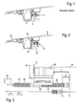
- FIG. 1 shown where a front end of a sunshade element 1 moved in its closed position over an upper end of a headliner 2 and a between the headliner 2 and the roof frame 3 existing gap is covered by a panel 4.
- a sunroof sunshade assembly for a vehicle has a sunshade element which is displaceable in an opening and a closing direction, which has a bow in the region of its free, front end and in which at least one force-transmitting drive element is provided connected to the bow and with a drive to move the sun protection element in a closed position.
- the front end of the sunshade element occupies a predetermined closed position in the closed position.
- At least one elastic intermediate element is provided, which is arranged in the force flow between the drive and the front end of the sunshade element.
- the drive is designed so that, after the front end of the sun protection element has reached the closed position, the drive element continues to move into a predetermined end position in which the intermediate element is elastically deformed.
- an elastic coupling between the front end of the sun protection element and the drive element which makes it possible to compensate for the tolerances in the displacement of the sun protection element in that the drive element is moved after reaching an end position to a position in which it is ensured that taking into account all tolerances, the sunshade element has reached its closed position.
- the End position of the drive element is the position at which the solar control element has just reached the closed position without inaccuracies of the system.
- the sun protection element remains in its closed position as soon as it has reached it.
- the further movement of the drive element is absorbed solely by the elastic intermediate element. In this way, a tolerance range in the range of about 10 mm can be compensated without problems.
- the clear width of the roof opening need not be artificially reduced by a panel to avoid that a gap between the front end of the sunshade element and the edge the roof opening could persist.
- the intermediate element when the sunshade element is in an open position, the intermediate element is more relaxed than in the closed position, so that the entire compression path of the intermediate element, which of course preferably corresponds to the maximum required tolerance path, can be used to compensate for tolerances in the drive path.
- the intermediate element is preferably designed as a compression spring, but can also be realized in the form of a tension spring.
- the closed position may advantageously coincide with a position in which the front end of the sun protection element rests against a portion of a headliner of the vehicle.
- the roof opening is closed in any case by sun protection element and headliner.
- the headliner may form a stop for the front end of the sunshade element.
- a force applied by the drive to the drive element force is greater than the spring force of the intermediate element. If the front end of the sunshade element is restrained by a stop, for example by abutment with a portion of the headliner, further forward movement of the drive element can be translated into compression of the intermediate element without further movement of the forward end of the sunshield element.
- the drive element is a tensile and pressure-rigid cable.
- the drive element could also be embodied in other ways, for example integrated in a roller blind (eg a self-winding spring steel strip at the edge of the roller blind).
- a sun protection element comes, for example, a flexible roller blind or a rigid solar panel in question.
- the principle of the invention is equally well implemented in both cases.
- the bow is arranged displaceably relative to the drive element. If the sunshade element is in its closed position and its front end is in the closed position, another method of the drive element is converted by the drive only into a movement of the drive element, while the hoop remains in its position. In this case, the bow can be firmly connected to the sun protection element.
- the intermediate element may be arranged, for example, between a stop fixed to the drive element and the bow, with maximum permissible displacement by the specified tolerance path between the drive element and the bow.
- the stop is e.g. formed at a free end of the drive element. The relative displacement is absorbed by compression of the intermediate element.
- the intermediate element relaxes again and, for example, automatically returns the bow to its starting position.
- the intermediate element can be, for example, a spiral spring, which surrounds the drive element.
- the bow is preferably fixedly attached to the intermediate element, so that the drive element can move relative to the bow against the resistance of the intermediate element.
- Between the bow and the drive element is advantageous only a linear movement in the direction of displacement, but no movement perpendicular to this direction possible so that an exact positioning of the drive element, the bow and the front end of the sun protection element is possible.
- the at least one elastic intermediate element is arranged between the front end of the sunshade element and the bow.
- the front end of the sunshade element therefore moves relative to the bow.
- the bow can be firmly connected to the drive element in this embodiment, while the front end of the Sun protection element should be arranged relative to the bow and relative to the body of the sun protection element to the tolerance path movable.
- the sun protection element may have a substantially rigid end element at the front end, which preferably extends over the entire width of the sun protection element.
- the one or more elastic intermediate elements are advantageously arranged so that a uniform across the width force application of the final element is given.
- a plurality of coil springs may be arranged as intermediate elements next to each other.
- At least one first guide part is formed in the end element and at least one second guide part cooperating therewith is formed in the bow, wherein the guide parts are displaceable relative to one another.
- recesses such as slots or holes in the bow and webs in the closing element (or vice versa) may be provided. It is advantageous if the intermediate elements are accommodated in the form of coil springs on a portion of the webs, since the intermediate elements are held in this way the same firm and deformable only in a linear direction.
- the invention also relates to a method for displacing a sunshade element of a sunroof sunshade assembly for a vehicle, which method is particularly suitable for one of the above-described sunroof sunshade assemblies.
- a free front end of the sun protection element is in a closed position against a stop, and a drive element is moved to move the sun protection element in the closed position by a drive in a predetermined end position.
- the predetermined end position corresponds to a position in which an elastic intermediate element arranged in the force flow between the front end of the sunshade element and the drive element is compressed by an amount within a predetermined tolerance path.
- the drive element is therefore moved further than it actually to reach the closed position of the free front end of the sunshade element would be required.
- the additional movement path is not converted into a movement of the front end of the sunshade element, but in a compression of the elastic intermediate element.
- the predetermined end position of the drive element can advantageously be specified by the drive. For example, it may correspond to a predetermined number of revolutions of an electric motor.
- the predetermined end position should be chosen so that in any case a compression of the intermediate element occurs.
- the intermediate element relaxes, and the bow or the end element of the sun protection element is preferably moved back into its starting position due to the restoring force provided by the intermediate element.
- FIG. 2 is a sunroof sunshade assembly 10 installed in a vehicle roof 12, not shown.
- a roof opening 14 is formed, which can be released or closed by a sunroof, not shown.
- a sun protection element 16 is arranged (in FIG. 2 indicated) that the roof opening 14 can cover.
- the sunshade element 16 has a transverse to the vehicle longitudinal axis, extending along the entire sunshade element 16 extending bow 20 which with a drive element 22 not shown here (see Figures 3 . 4 and 6 ), which transmits the power of a drive 24, for example in the form of an electric motor, to the sunshade element 16.
- a drive 24 for example in the form of an electric motor
- the front end 18 of the sun protection member 16 is in its closed position against a stop 26, which is formed in this case by a portion of the upper end of a headliner 28.
- FIG. 1 Compared with the prior art, the in FIG. 1 is shown here is that the headliner 28 a good distance further to the front end of the roof opening 14 (in the Figures 1 and 2 to the left) can be arranged. As a result, increased by the invention, the inside width of the roof opening 14 with respect to the known from the prior art assembly.
- the sunshade element When moving to the closed position, the sunshade element approaches the headliner 28 until, in the closed position, the front end 18 of the sunshade element 16 is in direct contact with a section of the headliner 28. At this point, of course, another stop could be provided on another vehicle-fixed component as the headliner 28.
- the sunshade element 16 may be a roller blind that is folded or wound at its other end, not shown, but it may also be a rigid component that is displaced under the roof skin.
- the bow 20 is in the region of the front end 18 of the sun protection element 16 (which is only indicated here) connected to the drive element 22, that it is mounted linearly displaceable relative to this.
- the drive element 22 is in this case a tensile and pressure-rigid cable.
- the bow 20 has a mounting portion 30 which engages around the drive element 22 and which is attached to an elastic intermediate element 32 designed as a spiral spring.
- the elastic intermediate element 32 in turn extends between the attachment portion 30 on the bow 20 and a drive element fixed Stop 34, to which it is also attached. Against the spring force of the elastic intermediate element 32, the bow 20 can be moved along the drive element 22, in particular in the direction of the stop 34, ie in the FIG. 3 to the right.
- the bow 20 and the sun protection element 16 are rigidly connected together here.
- the drive element 22 preferably extends in a guide rail, not shown. Normally, a drive element 22 is provided in each case on both sides of the sunshade element 16 in a guide rail. This construction can also be used here.
- the spring force of the intermediate resilient member 32 is selected to be greater than the force needed to move the sunshade member 16 from its open to closed position. In this movement, therefore, the sun protection element 16 is moved as if the bow 20 is rigidly connected to the drive element 22.
- the front end 18 of the sun protection element 16 comes into contact with the stop 26, which is formed here by a portion of the headliner 28.
- the front end 18 has reached its closed position, and the drive member 22 its ideal end position E i .
- the drive 24 is adjusted so that the movement of the drive element 22 is continued in the closing direction via this ideal end position E i .
- the drive moves the drive element 22 further in the closing direction until it has reached a predetermined end position E v .
- the two end positions E i , E v are in the FIG. 3 shown schematically at the rear free end of the drive member 22.
- the presetting of the predetermined end position E v occurs, for example, in that the number of revolutions of an electric motor, which forms the drive 24, is specified.
- the predetermined end position E v varies within a tolerance range T, which is approximately 10 mm.
- the intermediate element 32 is designed such that it can completely compensate this tolerance range T by its compression. Concretely, of course, only the actual difference D between the preset end position E v and the ideal end position E i is compensated.
- the compression of the elastic intermediate element 32 takes place in that the sun protection element 16 is retained at its front end 18 on the stop 26, whereby the bow 20 is held in this position. Since the bow 20 is movable relative to the drive element 22, the drive element 22 moves relative to the bow 20 to the left (in FIG. 3 ). In this case, the elastic intermediate element 32 is compressed. This movement takes place until the drive element 22 has taken the predetermined end position E v .
- the drive 24 moves the drive element 22 in the opposite direction (to the right in FIG. 3 ).
- the resilient intermediate member 32 relaxes, so that the bow 20 is returned to its original position, then moves the entire group of drive element 22, intermediate member 32, bow 20 and sun protection element 16 together without relative movement further in the opening direction.
- a second elastic intermediate element 35 may be provided, which is arranged between the bow 20 and a front stop, which is fastened to the drive element 22.
- the intermediate element 35 (here also a spiral spring) is compressed at the end of the opening movement when the bow 20 has moved against a stop. Even with the opening movement so a tolerance compensation is achieved by a further movement of the drive member 22.
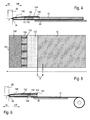
- FIGS. 4 to 7 show a second embodiment in which the elastic intermediate member 132 between the front end 18 of the sun protection element 16 and the bow 120 is arranged.
- the sunshade element 16 has at its front end 18 a closing element 140 which is designed as a rigid component which extends over the entire width of the sunshade element 16.
- the final element 140 and the bow 120 are mutually displaceable.
- the drive element 22 is in this case firmly connected to the bow 120, so that it is not movable relative to the body of the sun protection element 16 or the drive element 22.
- the intermediate elements 132 are all arranged between the closing element 140 and the bow 120.
- the closing element 140 and the bow 120 are connected to each other by first and second guide parts 142, 144 in such a way that they are guided linearly displaceable relative to one another.
- the first guide parts 142 are here formed by webs, one for each elastic intermediate element 132, which are formed integrally with the closing element 140 and which protrude in the direction of displacement of this.
- To each of the webs of one of the intermediate elements 132 is arranged, which are formed here as a spiral spring.
- respective corresponding recesses are formed as second guide parts 144, into which the webs protrude.
- the bow 120 and the closing element 140 are displaceable relative to each other, but guided in their movement with each other.
- a stop 146 is formed, against which one end of the elastic intermediate element 132 abuts.
- the elastic intermediate element 132 Upon a relative movement of closing element 140 and bow 120 towards each other, the elastic intermediate element 132 is compressed. When the force subsides, the intermediate element 132 relaxes and pushes the bow 120 and closing element 140 apart again to the original initial position in which the intermediate element 132 is relaxed.
- the drive 24 moves the drive element 22 in the opposite direction, in the FIGS. 4 to 6 to the right.
- the elastic intermediate elements 132 relax, so that the bow 120 and closing element 140 again assume their starting position relative to each other, and then the sun protection element 16 is moved into its open position.
- FIG. 4 shows the invention for a rigid sun protection element 16, for example in the form of a sunroof
- FIG. 6 shows the implementation of a flexible roller blind, which is arranged at its second end in a roller blind.
Landscapes
- Engineering & Computer Science (AREA)
- Mechanical Engineering (AREA)
- Operating, Guiding And Securing Of Roll- Type Closing Members (AREA)
- Power-Operated Mechanisms For Wings (AREA)
Abstract
Description
Die Erfindung betrifft eine Schiebedach-Sonnenschutzbaugruppe für ein Fahrzeug.The invention relates to a sunroof sunshade assembly for a vehicle.
Eine durch ein Schiebedach freigebbare oder gegebenenfalls auch eine durch ein Glasdach verschlossene Öffnung in einem Fahrzeugdach ist meist mit einem Sonnenschutzelement versehen, das die Fahrzeuginsassen zum Schutz vor Sonneneinstrahlung so verschieben können, dass es die Öffnung oder das Glasdach innenseitig ganz oder teilweise abdeckt. Ein derartiger Sonnenschutz ist auch deshalb wichtig, weil einfallende Sonnenstrahlung den Fahrer blenden kann. Dabei kann sich auch bereits ein kleiner Spalt zwischen dem vorderen Ende des Sonnenschutzelements und dem Rand der Dachöffnung als störend erweisen, durch den immer noch blendende Sonnenstrahlung einfallen kann. Es ist daher gewünscht, dass das vordere Ende des Sonnenschutzelements in seiner Schließposition den vorderen Teil der Dachöffnung zum Innenraum vollständig abdeckt.A releasable by a sunroof or optionally also a closed by a glass roof opening in a vehicle roof is usually provided with a sun protection element that can move the vehicle occupants to protect against sunlight so that it covers the opening or the glass roof inside completely or partially. Such sun protection is also important because incident solar radiation can dazzle the driver. In this case, even a small gap between the front end of the sun protection element and the edge of the roof opening may prove disturbing, can still occur through the blinding sunshine. It is therefore desirable that the front end of the sunshade element in its closed position completely covers the front part of the roof opening to the interior.
In den letzten Jahren haben sich zunehmend Sonnenschutzbaugruppen durchgesetzt, bei denen das Sonnenschutzelement durch einen Motor bewegt, also nicht mehr durch Handbetätigung verschoben wird. Toleranzen, die sich in der Baugruppe addieren, können hier dazu führen, dass die Endstellung des vorderen Endes des Sonnenschutzelements innerhalb eines Toleranzwegs variiert. Derartige Toleranzen ergeben sich beispielsweise aus der Bewegung des kraftübertragenden Antriebselements, das das Sonnenschutzelement bewegt und das in der Regel ein zugfestes und drucksteif geführtes Kabel ist. Weitere Toleranzen ergeben sich bei der Verwendung eines Rollos als Sonnenschutzelement beim Auf- und Abwickeln des Rollos oder aber auch durch Rohbautoleranzen.In recent years, sun protection assemblies have increasingly prevailed, in which the sun protection element moved by a motor, that is no longer moved by manual operation. Tolerances that add up in the assembly can lead to the fact that the end position of the front end of the sun protection element varies within a tolerance path. Such tolerances arise, for example, from the movement of the force-transmitting drive element, which moves the sun protection element and which is usually a tensile and pressure-rigid cable guided. Further tolerances arise at the use of a roller blind as a sun protection element during winding and unwinding of the blinds or even by shell tolerances.
Um diese Toleranzen zu kompensieren, wurde bisher am vorderen Ende der Dachöffnung eine Verkleidung angebracht, die das vordere Ende des Sonnenschutzelements in seiner Schließposition überdeckt, um sicherzustellen, dass hier kein Spalt frei bleibt. Der Nachteil dieser Lösung ist allerdings, dass die lichte Weite der Dachöffnung reduziert wird und somit sich für die Fahrzeuginsassen der Eindruck einer kleineren Dachöffnung ergibt.To compensate for these tolerances, a cladding was previously applied to the front end of the roof opening, which covers the front end of the sun protection element in its closed position to ensure that no gap remains free here. The disadvantage of this solution, however, is that the clear width of the roof opening is reduced, thus resulting in the impression of a smaller roof opening for the vehicle occupants.
Eine derartige bekannte Lösung ist in
Es ist Aufgabe der Erfindung, eine Schiebedach-Sonnenschutzbaugruppe für ein Fahrzeug zu schaffen, bei dem im Wesentlichen die ganze lichte Weite der Dachöffnung im geöffneten Zustand des Sonnenschutzelements offen liegt.It is an object of the invention to provide a sunroof sunshade assembly for a vehicle, in which substantially the entire inside width of the roof opening in the open state of the sunshade element is open.
Erfindungsgemäß wird das folgendermaßen realisiert: Eine Schiebedach-Sonnenschutzbaugruppe für ein Fahrzeug hat ein Sonnenschutzelement, das in eine Öffnungs- und eine Schließrichtung verschiebbar ist, das im Bereich seines freien, vorderen Endes einen Spriegel aufweist und bei dem wenigstens ein kraftübertragendes Antriebselement vorgesehen ist, das mit dem Spriegel und mit einem Antrieb verbunden ist, um das Sonnenschutzelement in eine geschlossene Stellung zu verschieben. Das vordere Ende des Sonnenschutzelements nimmt in der geschlossenen Stellung eine vorbestimmte Schließposition ein. Es ist wenigstens ein elastisches Zwischenelement vorgesehen, das im Kraftfluss zwischen dem Antrieb und dem vorderen Ende des Sonnenschutzelements angeordnet ist. Dabei ist der Antrieb so ausgelegt, dass er, nachdem das vordere Ende des Sonnenschutzelements die Schließposition erreicht hat, das Antriebselement in eine vorbestimmte Endstellung weiterbewegt, in der das Zwischenelement elastisch deformiert ist.According to the invention, this is realized as follows: A sunroof sunshade assembly for a vehicle has a sunshade element which is displaceable in an opening and a closing direction, which has a bow in the region of its free, front end and in which at least one force-transmitting drive element is provided connected to the bow and with a drive to move the sun protection element in a closed position. The front end of the sunshade element occupies a predetermined closed position in the closed position. At least one elastic intermediate element is provided, which is arranged in the force flow between the drive and the front end of the sunshade element. In this case, the drive is designed so that, after the front end of the sun protection element has reached the closed position, the drive element continues to move into a predetermined end position in which the intermediate element is elastically deformed.
Es ist erfindungsgemäß eine elastische Kopplung zwischen dem vorderen Ende des Sonnenschutzelements und dem Antriebselement vorgesehen, die es erlaubt, die Toleranzen im Verschiebeweg des Sonnenschutzelements dadurch auszugleichen, dass das Antriebselement nach Erreichen einer Endstellung bis in eine Position weiterbewegt wird, in der sichergestellt ist, dass unter Berücksichtigung aller Toleranzen das Sonnenschutzelement seine Schließposition erreicht hat. Die Endstellung des Antriebselements ist die Position, bei der ohne Ungenauigkeiten des Systems das Sonnenschutzelement die Schließposition gerade erreicht hat. Das Sonnenschutzelement verharrt in seiner Schließposition, sobald es diese erreicht hat. Die weitere Bewegung des Antriebselements wird allein vom elastischen Zwischenelement aufgenommen. Auf diese Weise lässt sich ein Toleranzweg im Bereich von etwa 10 mm ohne Probleme ausgleichen.It is provided according to the invention an elastic coupling between the front end of the sun protection element and the drive element, which makes it possible to compensate for the tolerances in the displacement of the sun protection element in that the drive element is moved after reaching an end position to a position in which it is ensured that taking into account all tolerances, the sunshade element has reached its closed position. The End position of the drive element is the position at which the solar control element has just reached the closed position without inaccuracies of the system. The sun protection element remains in its closed position as soon as it has reached it. The further movement of the drive element is absorbed solely by the elastic intermediate element. In this way, a tolerance range in the range of about 10 mm can be compensated without problems.
Da sichergestellt ist, dass bei jedem Schließen des Sonnenschutzelements dessen vorderes Ende exakt in der Schließposition endet, braucht die lichte Weite der Dachöffnung nicht künstlich durch eine Verkleidung verkleinert zu werden, um zu vermeiden, dass ein Spalt zwischen dem vorderen Ende des Sonnenschutzelements und dem Rand der Dachöffnung bestehen bleiben könnte.Since it is ensured that with each closing of the sunshade element whose front end terminates exactly in the closed position, the clear width of the roof opening need not be artificially reduced by a panel to avoid that a gap between the front end of the sunshade element and the edge the roof opening could persist.
Vorzugsweise ist das Zwischenelement, wenn sich das Sonnenschutzelement in einer geöffneten Stellung befindet, entspannter als in der Schließposition, sodass der gesamte Kompressionsweg des Zwischenelements, der natürlich vorzugsweise dem maximal benötigten Toleranzweg entspricht, zum Ausgleich von Toleranzen im Antriebsweg genutzt werden kann.Preferably, when the sunshade element is in an open position, the intermediate element is more relaxed than in the closed position, so that the entire compression path of the intermediate element, which of course preferably corresponds to the maximum required tolerance path, can be used to compensate for tolerances in the drive path.
Das Zwischenelement ist bevorzugt als Druckfeder ausgebildet, kann aber auch in Form einer Zugfeder realisiert sein.The intermediate element is preferably designed as a compression spring, but can also be realized in the form of a tension spring.
Die Schließposition kann vorteilhaft mit einer Position zusammenfallen, in der das vordere Ende des Sonnenschutzelements an einem Abschnitt eines Dachhimmels des Fahrzeugs anliegt. Auf diese Weise ist die Dachöffnung auf jeden Fall durch Sonnenschutzelement und Dachhimmel verschlossen. Der Dachhimmel kann einen Anschlag für das vordere Ende des Sonnenschutzelements bilden.The closed position may advantageously coincide with a position in which the front end of the sun protection element rests against a portion of a headliner of the vehicle. In this way, the roof opening is closed in any case by sun protection element and headliner. The headliner may form a stop for the front end of the sunshade element.
Dabei ist vorzugsweise eine vom Antrieb auf das Antriebselement aufgebrachte Kraft größer als die Federkraft des Zwischenelements. Wird das vordere Ende des Sonnenschutzelements durch einen Anschlag zurückgehalten, beispielsweise durch die Anlage an einem Abschnitt des Dachhimmels, kann eine weitere Vorwärtsbewegung des Antriebselements in eine Kompression des Zwischenelements umgesetzt werden, ohne dass eine weitere Bewegung des vorderen Endes des Sonnenschutzelements erfolgt.In this case, preferably a force applied by the drive to the drive element force is greater than the spring force of the intermediate element. If the front end of the sunshade element is restrained by a stop, for example by abutment with a portion of the headliner, further forward movement of the drive element can be translated into compression of the intermediate element without further movement of the forward end of the sunshield element.
In einer bevorzugten Ausführungsform der Erfindung ist das Antriebselement ein zugfestes und drucksteif geführtes Kabel. Natürlich könnte das Antriebselement auch auf andere Weise, etwa in ein Rollo integriert, ausgeführt sein (z.B. ein selbstaufrollendes Federstahlband am Rand des Rollos).In a preferred embodiment of the invention, the drive element is a tensile and pressure-rigid cable. Of course, the drive element could also be embodied in other ways, for example integrated in a roller blind (eg a self-winding spring steel strip at the edge of the roller blind).
Als Sonnenschutzelement kommt beispielsweise ein flexibles Rollo oder auch ein starres Sonnenpaneel infrage. Das Prinzip der Erfindung ist in beiden Fällen gleichermaßen gut umzusetzen.As a sun protection element comes, for example, a flexible roller blind or a rigid solar panel in question. The principle of the invention is equally well implemented in both cases.
In einer ersten bevorzugten Ausführungsform der Erfindung ist der Spriegel relativ zum Antriebselement verschiebbar angeordnet. Befindet sich das Sonnenschutzelement in seiner geschlossenen Stellung und dessen vorderes Ende in der Schließposition, so wird ein weiteres Verfahren des Antriebselements durch den Antrieb nur in eine Bewegung des Antriebselements umgesetzt, während der Spriegel an seiner Position verharrt. In diesem Fall kann der Spriegel fest mit dem Sonnenschutzelement verbunden sein.In a first preferred embodiment of the invention, the bow is arranged displaceably relative to the drive element. If the sunshade element is in its closed position and its front end is in the closed position, another method of the drive element is converted by the drive only into a movement of the drive element, while the hoop remains in its position. In this case, the bow can be firmly connected to the sun protection element.
Das Zwischenelement kann beispielsweise zwischen einem antriebselementfesten Anschlag und dem Spriegel angeordnet sein, wobei maximal eine Verschiebung um den festgelegten Toleranzweg zwischen Antriebselement und Spriegel zugelassen ist. Der Anschlag ist z.B. an einem freien Ende des Antriebselements ausgebildet. Die Relativverschiebung wird durch Kompression des Zwischenelements aufgenommen.The intermediate element may be arranged, for example, between a stop fixed to the drive element and the bow, with maximum permissible displacement by the specified tolerance path between the drive element and the bow. The stop is e.g. formed at a free end of the drive element. The relative displacement is absorbed by compression of the intermediate element.
Wenn sich das Sonnenschutzelement aus seiner geschlossenen wieder in eine geöffnete Stellung bewegt, entspannt sich das Zwischenelement wieder und stellt den Spriegel beispielsweise automatisch in seine Ausgangslage zurück.When the sun protection element moves from its closed back to an open position, the intermediate element relaxes again and, for example, automatically returns the bow to its starting position.
Das Zwischenelement kann beispielsweise eine Spiralfeder sein, die das Antriebselement umgreift.The intermediate element can be, for example, a spiral spring, which surrounds the drive element.
Der Spriegel ist dabei vorzugsweise fest am Zwischenelement befestigt, sodass sich das Antriebselement gegen den Widerstand des Zwischenelements relativ zum Spriegel bewegen kann. Zwischen dem Spriegel und dem Antriebselement ist vorteilhaft nur eine lineare Bewegung in Verschieberichtung, aber keine Bewegung senkrecht zu dieser Richtung möglich, damit eine exakte Positionierung des Antriebselements, des Spriegels und des vorderen Endes des Sonnenschutzelements möglich ist.The bow is preferably fixedly attached to the intermediate element, so that the drive element can move relative to the bow against the resistance of the intermediate element. Between the bow and the drive element is advantageous only a linear movement in the direction of displacement, but no movement perpendicular to this direction possible so that an exact positioning of the drive element, the bow and the front end of the sun protection element is possible.
Nach einer zweiten vorteilhaften Ausführungsform der Erfindung ist das wenigstens eine elastische Zwischenelement zwischen dem vorderen Ende des Sonnenschutzelements und dem Spriegel angeordnet. In diesem Fall bewegt sich bei einer Komprimierung des Zwischenelements also das vordere Ende des Sonnenschutzelements relativ zum Spriegel. Der Spriegel kann in diesem Ausführungsbeispiel fest mit dem Antriebselement verbunden sein, während das vordere Ende des Sonnenschutzelements relativ zum Spriegel und relativ zum Körper des Sonnenschutzelements um den Toleranzweg beweglich angeordnet sein sollte.According to a second advantageous embodiment of the invention, the at least one elastic intermediate element is arranged between the front end of the sunshade element and the bow. In this case, when the intermediate element is compressed, the front end of the sunshade element therefore moves relative to the bow. The bow can be firmly connected to the drive element in this embodiment, while the front end of the Sun protection element should be arranged relative to the bow and relative to the body of the sun protection element to the tolerance path movable.
Hierbei ist für eine präzise Positionierung vorteilhaft, wenn das vordere Ende des Sonnenschutzelements, das Zwischenelement und der Spriegel im Wesentlichen linear aufeinanderfolgend angeordnet sind. Auf diese Weise kann eine über das Antriebselement übertragene Kraft ohne Kraftkomponenten senkrecht zur Verschieberichtung in das Zwischenelement eingeleitet werden.In this case, it is advantageous for a precise positioning if the front end of the sun protection element, the intermediate element and the bow are arranged substantially linearly successively. In this way, transmitted via the drive element force can be introduced without force components perpendicular to the direction in the intermediate element.
Das Sonnenschutzelement kann dabei ein im Wesentlichen starres Abschlusselement am vorderen Ende aufweisen, das sich bevorzugt über die gesamte Breite des Sonnenschutzelements erstreckt. Das oder die elastischen Zwischenelemente sind vorteilhaft so angeordnet, dass eine über die Breite gleichmäßige Kraftbeaufschlagung des Abschlusselements gegeben ist. Hierbei können beispielsweise mehrere Spiralfedern als Zwischenelemente nebeneinander angeordnet sein.The sun protection element may have a substantially rigid end element at the front end, which preferably extends over the entire width of the sun protection element. The one or more elastic intermediate elements are advantageously arranged so that a uniform across the width force application of the final element is given. In this case, for example, a plurality of coil springs may be arranged as intermediate elements next to each other.
Vorzugsweise ist im Abschlusselement wenigstens ein erstes Führungsteil und im Spriegel wenigstens ein damit zusammenwirkendes zweites Führungsteil ausgebildet, wobei die Führungsteile gegeneinander verschiebbar sind. Beispielsweise können Ausnehmungen wie Schlitze oder Bohrungen im Spriegel und Stege im Abschlusselement (oder umgekehrt) vorgesehen sein. Hierbei ist es vorteilhaft, wenn die Zwischenelemente in Form von Spiralfedern an einem Abschnitt der Stege aufgenommen sind, da die Zwischenelemente auf diese Weise gleich fest gehalten und nur in linearer Richtung verformbar angeordnet sind.Preferably, at least one first guide part is formed in the end element and at least one second guide part cooperating therewith is formed in the bow, wherein the guide parts are displaceable relative to one another. For example, recesses such as slots or holes in the bow and webs in the closing element (or vice versa) may be provided. It is advantageous if the intermediate elements are accommodated in the form of coil springs on a portion of the webs, since the intermediate elements are held in this way the same firm and deformable only in a linear direction.
Die Erfindung betrifft auch ein Verfahren zum Verschieben eines Sonnenschutzelements einer Schiebedach-Sonnenschutzbaugruppe für ein Fahrzeug, wobei dieses Verfahren insbesondere für eine der oben beschriebenen Schiebedach-Sonnenschutzbaugruppen geeignet ist.The invention also relates to a method for displacing a sunshade element of a sunroof sunshade assembly for a vehicle, which method is particularly suitable for one of the above-described sunroof sunshade assemblies.
Dabei liegt ein freies vorderes Ende des Sonnenschutzelements in einer Schließposition an einem Anschlag an, und ein Antriebselement wird zum Verfahren des Sonnenschutzelements in die geschlossene Stellung durch einen Antrieb in eine vorbestimmte Endstellung bewegt. Die vorbestimmte Endstellung entspricht einer Position, in der ein im Kraftfluss zwischen dem vorderen Ende des Sonnenschutzelements und dem Antriebselement angeordnetes elastisches Zwischenelement um einen Betrag innerhalb eines vorbestimmten Toleranzwegs komprimiert ist.In this case, a free front end of the sun protection element is in a closed position against a stop, and a drive element is moved to move the sun protection element in the closed position by a drive in a predetermined end position. The predetermined end position corresponds to a position in which an elastic intermediate element arranged in the force flow between the front end of the sunshade element and the drive element is compressed by an amount within a predetermined tolerance path.
Das Antriebselement wird demnach weiter bewegt als es zum Erreichen der Schließposition des freien vorderen Endes des Sonnenschutzelements eigentlich erforderlich wäre. Der zusätzliche Bewegungsweg wird jedoch nicht in eine Bewegung des vorderen Endes des Sonnenschutzelements, sondern in eine Komprimierung des elastischen Zwischenelements umgesetzt.The drive element is therefore moved further than it actually to reach the closed position of the free front end of the sunshade element would be required. However, the additional movement path is not converted into a movement of the front end of the sunshade element, but in a compression of the elastic intermediate element.
Die vorbestimmte Endstellung des Antriebselements kann dabei vorteilhaft durch den Antrieb vorgegeben werden. Sie kann beispielsweise einer vorher festgelegten Anzahl von Umdrehungen eines Elektromotors entsprechen. Die vorbestimmte Endstellung sollte dabei so gewählt sein, dass in jedem Fall eine Komprimierung des Zwischenelements auftritt.The predetermined end position of the drive element can advantageously be specified by the drive. For example, it may correspond to a predetermined number of revolutions of an electric motor. The predetermined end position should be chosen so that in any case a compression of the intermediate element occurs.
Wird das Sonnenschutzelement wieder in seine geöffnete Stellung zurückverfahren, entspannt sich das Zwischenelement, und der Spriegel oder das Abschlusselement des Sonnenschutzelements werden bevorzugt aufgrund der durch das Zwischenelement gelieferten Rückstellkraft wieder in ihre Ausgangsstellung zurückbewegt.If the sun protection element is returned to its open position, the intermediate element relaxes, and the bow or the end element of the sun protection element is preferably moved back into its starting position due to the restoring force provided by the intermediate element.
Weitere Merkmale und Vorteile der Erfindung ergeben sich aus der nachfolgenden Beschreibung zweier Ausführungsbeispiele in Verbindung mit den beigefügten Zeichnungen. In diesen zeigen:
-
Figur 1 -
Figur 2 eine schematische Schnittansicht einer erfindungsgemäßen Schiebedach-Sonnenschutzbaugruppe; -
Figur 3 einen Ausschnitt aus einer erfindungsgemäßen Schiebedach-Sonnenschutzbaugruppe gemäß einer ersten Ausführungsform; -
Figur 4 -
Figur 5 dieBaugruppe aus Figur 4 in einer Draufsicht; und -
Figur 6 eine Variante der inFigur 4
-
FIG. 1 a schematic sectional view of a sunroof sunshade assembly according to the prior art; -
FIG. 2 a schematic sectional view of a sunroof sunshade assembly according to the invention; -
FIG. 3 a section of a sunroof sunshade assembly according to the invention according to a first embodiment; -
FIG. 4 a schematic sectional view of a section of a sunroof sunshade assembly according to the invention according to a second embodiment; -
FIG. 5 the module offFIG. 4 in a plan view; and -
FIG. 6 a variant of inFIG. 4 shown assembly in a schematic sectional view.
In
In der in
Verglichen mit dem Stand der Technik, der in
Beim Verfahren in die geschlossene Stellung fährt das Sonnenschutzelement an den Dachhimmel 28 heran, bis in der Schließposition das vordere Ende 18 des Sonnenschutzelements 16 in direktem Kontakt mit einem Abschnitt des Dachhimmels 28 ist. An dieser Stelle könnte natürlich auch ein anderer Anschlag an einem anderen fahrzeugfesten Bauteil als dem Dachhimmel 28 vorgesehen sein.When moving to the closed position, the sunshade element approaches the
Das Sonnenschutzelement 16 kann ein Rollo sein, das an seinem anderen, nicht gezeigten Ende gefaltet oder gewickelt aufgenommen ist, es kann aber auch ein starres Bauteil sein, das unter die Dachhaut verschoben wird.The
Bei der in
Der Spriegel 20 hat einen Befestigungsabschnitt 30, der das Antriebselement 22 umgreift und der an einem als Spiralfeder ausgebildeten elastischen Zwischenelement 32 befestigt ist. Das elastische Zwischenelement 32 wiederum erstreckt sich zwischen dem Befestigungsabschnitt 30 am Spriegel 20 und einem antriebselementfesten Anschlag 34, an dem es ebenfalls befestigt ist. Gegen die Federkraft des elastischen Zwischenelements 32 kann der Spriegel 20 entlang des Antriebselements 22 bewegt werden, insbesondere in Richtung zum Anschlag 34, also in der
Der Spriegel 20 und das Sonnenschutzelement 16 sind hier starr miteinander verbunden.The
Das Antriebselement 22 verläuft vorzugsweise in einer nicht gezeigten Führungsschiene. Normalerweise ist an beiden Seiten des Sonnenschutzelements 16 je ein Antriebselement 22 in einer Führungsschiene vorgesehen. Diese Konstruktion kann auch hier verwendet werden.The
Bei einer Bewegung des Sonnenschutzelements 16 in Schließrichtung hin zur geschlossenen Stellung (nach links in
Die Federkraft des elastischen Zwischenelements 32 ist so gewählt, dass sie größer ist als die Kraft, die benötigt wird, um das Sonnenschutzelement 16 aus seiner geöffneten in die geschlossene Stellung zu bewegen. Bei dieser Verfahrbewegung wird also das Sonnenschutzelement 16 so bewegt, als wäre der Spriegel 20 starr mit dem Antriebselement 22 verbunden.The spring force of the intermediate
Im Verlauf der Schließbewegung gelangt das vordere Ende 18 des Sonnenschutzelements 16 in Anlage an den Anschlag 26, der hier durch einen Abschnitt des Dachhimmels 28 gebildet ist. Damit hat das vordere Ende 18 seine Schließposition erreicht, und das Antriebselement 22 seine ideale Endstellung Ei. Der Antrieb 24 ist jedoch so eingestellt, dass die Bewegung des Antriebselements 22 in Schließrichtung über diese ideale Endstellung Ei fortgesetzt wird. Der Antrieb bewegt das Antriebselement 22 weiter in Schließrichtung, bis es eine vorbestimmte Endstellung Ev erreicht hat.In the course of the closing movement, the
Die beiden Endstellungen Ei, Ev sind in der
Das Voreinstellen der vorbestimmten Endstellung Ev geschieht beispielsweise dadurch, dass die Anzahl der Umdrehungen eines Elektromotors, der den Antrieb 24 bildet, vorgegeben wird. Abhängig von den Toleranzen der Positionen des Sonnenschutzelements 16 und des Antriebselements 22 oder auch von der Genauigkeit der Wicklung des aufgewickelten Teils eines Rollos variiert die vorgegebene Endstellung Ev innerhalb eines Toleranzbereichs T, der in etwa 10 mm beträgt.The presetting of the predetermined end position E v occurs, for example, in that the number of revolutions of an electric motor, which forms the
Das Zwischenelement 32 ist so ausgelegt, dass es durch seine Komprimierung diesen Toleranzbereich T vollständig ausgleichen kann. Konkret wird natürlich immer nur die aktuelle Differenz D zwischen der voreingestellten Endstellung Ev und der idealen Endstellung Ei ausgeglichen.The
Die Komprimierung des elastischen Zwischenelements 32 erfolgt dadurch, dass das Sonnenschutzelement 16 an seinem vorderen Ende 18 am Anschlag 26 zurückgehalten wird, wodurch auch der Spriegel 20 in dieser Position festgehalten wird. Da der Spriegel 20 gegenüber dem Antriebselement 22 beweglich ist, verfährt das Antriebselement 22 relativ zum Spriegel 20 nach links (in
Da stets ein Überfahren der idealen Endstellung Ei erfolgt, ist immer sichergestellt, dass das vordere Ende 18 des Sonnenschutzelements 16 tatsächlich in Anlage an den Anschlag 26 gelangt und somit die Dachöffnung 14 spaltfrei verschlossen wird.Since there is always a crossing of the ideal end position E i , it is always ensured that the
Wenn das Sonnenschutzelement 16 wieder in seine geöffnete Stellung verfahren wird, um die Dachöffnung 14 freizugeben, bewegt der Antrieb 24 das Antriebselement 22 in die entgegengesetzte Richtung (nach rechts in
Optional kann ein zweites elastisches Zwischenelement 35 vorgesehen sein, welches zwischen Spriegel 20 und einem vorderen Anschlag angeordnet ist, welcher am Antriebselement 22 befestigt ist. Im dargestellten Beispiel wird das Zwischenelement 35 (hier ebenfalls eine Spiralfeder) am Ende der Öffnungsbewegung komprimiert, wenn der Spriegel 20 gegen einen Anschlag gefahren ist. Auch bei der Öffnungsbewegung wird also ein Toleranzausgleich durch ein Weiterbewegen des Antriebselements 22 erreicht.Optionally, a second elastic
Die
Das Sonnenschutzelement 16 weist an seinem vorderen Ende 18 ein Abschlusselement 140 auf, das als starres Bauteil ausgebildet ist, das sich über die gesamte Breite des Sonnenschutzelements 16 erstreckt. Das Abschlusselement 140 und der Spriegel 120 sind gegeneinander verschiebbar ausgebildet. Das Antriebselement 22 ist in diesem Fall fest mit dem Spriegel 120 verbunden, sodass dieser weder gegenüber dem Körper des Sonnenschutzelements 16 noch dem Antriebselement 22 beweglich ist.The
Es sind mehrere elastische Zwischenelemente 132 vorgesehen, in diesem Fall fünf, die nebeneinander über die Breite des Sonnenschutzelements 16 gleichmäßig verteilt angeordnet sind, wie
Das Abschlusselement 140 und der Spriegel 120 sind durch erste und zweite Führungsteile 142, 144 miteinander so verbunden, dass sie geführt linear gegeneinander verschieblich sind. Die ersten Führungsteile 142 sind hier durch Stege gebildet, einer für jedes elastische Zwischenelement 132, die einstückig mit dem Abschlusselement 140 ausgebildet sind und die in Verschieberichtung von diesem abstehen. Um jeden der Stege ist eines der Zwischenelemente 132 angeordnet, die hier als Spiralfeder ausgebildet sind.The
Im Spriegel 120 sind als zweite Führungsteile 144 jeweils entsprechende Ausnehmungen ausgebildet, in die die Stege hineinragen. Auf diese Weise sind der Spriegel 120 und das Abschlusselement 140 relativ zueinander verschiebbar, aber in ihrer Bewegung geführt miteinander verbunden.In the
Am vorderen Ende jeder der Ausnehmungen im Spriegel 120 ist ein Anschlag 146 ausgebildet, an dem ein Ende des elastischen Zwischenelements 132 anliegt.At the front end of each of the recesses in the
Bei einer Relativbewegung von Abschlusselement 140 und Spriegel 120 aufeinander zu wird das elastische Zwischenelement 132 komprimiert. Wenn die Krafteinwirkung nachlässt, entspannt sich das Zwischenelement 132 und drückt Spriegel 120 und Abschlusselement 140 wieder auseinander bis in die ursprüngliche Ausgangslage, in der das Zwischenelement 132 entspannt ist.Upon a relative movement of closing
Es wäre natürlich auch möglich, mehr oder weniger elastische Zwischenelemente 132 vorzusehen oder die Anordnung von Stegen und Ausnehmungen umgekehrt zu verwirklichen.It would of course also be possible to provide more or less elastic
Zum Schließen wird das Sonnenschutzelement 16 durch den hier nicht gezeigten Antrieb 24 nach links in den
Bei der Bewegung in die entgegengesetzte Richtung zum Öffnen des Sonnenschutzelements 16 bewegt der Antrieb 24 das Antriebselement 22 in die entgegengesetzte Richtung, in den
Claims (13)
einem Sonnenschutzelement (16), das in eine Öffnungs- und eine Schließrichtung verschiebbar ist und das im Bereich seines freien, vorderen Endes (18) einen Spriegel (20; 120) aufweist,
wenigstens einem kraftübertragenden Antriebselement (22), das mit dem Spriegel (20; 120) und mit einem Antrieb (24) verbunden ist, um das Sonnenschutzelement (16) in eine geschlossene Stellung zu verschieben, wobei das vordere Ende (18) des Sonnenschutzelements (16) in der geschlossenen Stellung eine vorbestimmte Schließposition einnimmt, und
mit wenigstens einem elastischen Zwischenelement (32; 132), das im Kraftfluss zwischen dem Antrieb (24) und dem vorderen Ende (18) des Sonnenschutzelements (16) angeordnet ist,
wobei der Antrieb (24) so ausgelegt ist, dass er, nachdem das vordere Ende (18) des Sonnenschutzelements (16) die Schließposition erreicht hat, das Antriebselement (22) in eine vorbestimmte Endstellung (Ev) weiterbewegt, in der das Zwischenelement (32; 132) elastisch deformiert ist.Sunroof sunshade assembly for a vehicle, with
a sunshade element (16) which is displaceable in an opening and a closing direction and which has a bow (20; 120) in the region of its free front end (18),
at least one force-transmitting drive element (22) which is connected to the bow (20; 120) and to a drive (24) in order to move the sunshade element (16) into a closed position, the front end (18) of the sunshield element (18) 16) assumes a predetermined closed position in the closed position, and
with at least one elastic intermediate element (32; 132) which is arranged in the force flow between the drive (24) and the front end (18) of the sun protection element (16),
wherein the drive (24) is designed such that, after the front end (18) of the sunshade element (16) has reached the closed position, it moves the drive element (22) to a predetermined end position (E v ), in which the intermediate element ( 32, 132) is elastically deformed.
ein freies vorderes Ende (18) des Sonnenschutzelements (16) in einer Schließposition an einem Anschlag (26) anliegt und
ein Antriebselement (22) zum Verfahren des Sonnenschutzelements (16) in die geschlossene Stellung durch einen Antrieb (24) in eine vorbestimmte Endstellung (Ev) bewegt wird,
wobei die vorbestimmte Endstellung (Ev) einer Position entspricht, in der ein im Kraftfluss zwischen dem vorderen Ende (18) des Sonnenschutzelements (16) und dem Antriebselement (22) angeordnetes elastisches Zwischenelement (32; 132) um einen Betrag (D) innerhalb eines vorbestimmten Toleranzwegs (T) komprimiert ist.Method for displacing a sunshade element of a sunroof sunshade assembly (10) for a vehicle, in particular according to one of the preceding claims, in which
a free front end (18) of the sun protection element (16) in a closed position against a stop (26) and abuts
a drive element (22) for moving the sunshade element (16) into the closed position is moved by a drive (24) into a predetermined end position (E v ),
wherein the predetermined end position (E v ) corresponds to a position in which an elastic intermediate element (32, 132) arranged in the force flow between the front end (18) of the sun protection element (16) and the drive element (22) is displaced by an amount (D) within a predetermined tolerance path (T) is compressed.
Priority Applications (3)
| Application Number | Priority Date | Filing Date | Title |
|---|---|---|---|
| EP09014901A EP2329978B1 (en) | 2009-12-01 | 2009-12-01 | Assembly including a sun-roof and a sun-screen |
| CN201010570449.3A CN102079234B (en) | 2009-12-01 | 2010-11-24 | Sliding roof sunshade assembly |
| US12/955,967 US8573684B2 (en) | 2009-12-01 | 2010-11-30 | Sliding roof sunshade assembly |
Applications Claiming Priority (1)
| Application Number | Priority Date | Filing Date | Title |
|---|---|---|---|
| EP09014901A EP2329978B1 (en) | 2009-12-01 | 2009-12-01 | Assembly including a sun-roof and a sun-screen |
Publications (2)
| Publication Number | Publication Date |
|---|---|
| EP2329978A1 true EP2329978A1 (en) | 2011-06-08 |
| EP2329978B1 EP2329978B1 (en) | 2013-02-13 |
Family
ID=42111009
Family Applications (1)
| Application Number | Title | Priority Date | Filing Date |
|---|---|---|---|
| EP09014901A Not-in-force EP2329978B1 (en) | 2009-12-01 | 2009-12-01 | Assembly including a sun-roof and a sun-screen |
Country Status (3)
| Country | Link |
|---|---|
| US (1) | US8573684B2 (en) |
| EP (1) | EP2329978B1 (en) |
| CN (1) | CN102079234B (en) |
Cited By (1)
| Publication number | Priority date | Publication date | Assignee | Title |
|---|---|---|---|---|
| WO2019042820A1 (en) * | 2017-08-31 | 2019-03-07 | Webasto SE | Shade roller apparatus |
Families Citing this family (5)
| Publication number | Priority date | Publication date | Assignee | Title |
|---|---|---|---|---|
| EP2774793A1 (en) * | 2013-03-04 | 2014-09-10 | Webasto SE | Vehicle sliding roof device |
| DE102013008898A1 (en) * | 2013-05-27 | 2014-11-27 | Webasto SE | vehicle roof |
| PL3216637T3 (en) * | 2016-03-07 | 2020-06-29 | Webasto SE | Drive cable having a plastics cable body |
| DE102018101557A1 (en) * | 2017-08-03 | 2019-02-07 | Webasto SE | Roller blind arrangement with guide strips for roller blind |
| CN112878602B (en) * | 2021-01-26 | 2022-03-22 | 南京武家嘴门窗装饰有限公司 | Intelligent sunshade integrated system window |
Citations (3)
| Publication number | Priority date | Publication date | Assignee | Title |
|---|---|---|---|---|
| DE4041341A1 (en) * | 1990-12-21 | 1992-06-25 | Bayerische Motoren Werke Ag | Sun roller blind for curved vehicle window - has flexible gravity bar adapting to curvature when installed |
| DE202005020610U1 (en) * | 2005-12-28 | 2006-05-04 | Bos Gmbh & Co. Kg | Blind arrangement for e.g. roof, for motor vehicle, has holder which sets up stopper for pivot, if blind track is removed against effect of motor, so that pivot is held abutting against stoppers through bias of motor in slot |
| DE102005030973A1 (en) * | 2005-06-30 | 2007-01-11 | Webasto Ag | Roller blind arrangement for a motor vehicle |
Family Cites Families (5)
| Publication number | Priority date | Publication date | Assignee | Title |
|---|---|---|---|---|
| GB2147432B (en) * | 1983-09-28 | 1987-01-14 | Aisin Seiki | Controlling movement |
| CN2033358U (en) * | 1988-02-01 | 1989-03-01 | 林荣生 | Automatic sunshading device for car |
| JP3339695B2 (en) * | 1991-06-27 | 2002-10-28 | マツダ株式会社 | Control mechanism of sunroof device |
| DE69604428T2 (en) * | 1995-01-26 | 2000-05-31 | Inalfa Ind Bv | Sun roof for a vehicle |
| US6299245B1 (en) * | 1999-11-15 | 2001-10-09 | Honda Giken Kogyo Kabushiki Kaisha | Wind deflector and sunshade stopping system, and method of using same |
-
2009
- 2009-12-01 EP EP09014901A patent/EP2329978B1/en not_active Not-in-force
-
2010
- 2010-11-24 CN CN201010570449.3A patent/CN102079234B/en not_active Expired - Fee Related
- 2010-11-30 US US12/955,967 patent/US8573684B2/en not_active Expired - Fee Related
Patent Citations (3)
| Publication number | Priority date | Publication date | Assignee | Title |
|---|---|---|---|---|
| DE4041341A1 (en) * | 1990-12-21 | 1992-06-25 | Bayerische Motoren Werke Ag | Sun roller blind for curved vehicle window - has flexible gravity bar adapting to curvature when installed |
| DE102005030973A1 (en) * | 2005-06-30 | 2007-01-11 | Webasto Ag | Roller blind arrangement for a motor vehicle |
| DE202005020610U1 (en) * | 2005-12-28 | 2006-05-04 | Bos Gmbh & Co. Kg | Blind arrangement for e.g. roof, for motor vehicle, has holder which sets up stopper for pivot, if blind track is removed against effect of motor, so that pivot is held abutting against stoppers through bias of motor in slot |
Cited By (1)
| Publication number | Priority date | Publication date | Assignee | Title |
|---|---|---|---|---|
| WO2019042820A1 (en) * | 2017-08-31 | 2019-03-07 | Webasto SE | Shade roller apparatus |
Also Published As
| Publication number | Publication date |
|---|---|
| EP2329978B1 (en) | 2013-02-13 |
| US8573684B2 (en) | 2013-11-05 |
| CN102079234A (en) | 2011-06-01 |
| US20110127806A1 (en) | 2011-06-02 |
| CN102079234B (en) | 2015-02-25 |
Similar Documents
| Publication | Publication Date | Title |
|---|---|---|
| EP1449692B1 (en) | Sun shade system for a vehicle | |
| EP2329978B1 (en) | Assembly including a sun-roof and a sun-screen | |
| DE10057764B4 (en) | Window blind with variable shading effect | |
| DE102010018259B4 (en) | Vehicle roller blind assembly, assembly with a vehicle blind assembly, and roof assembly | |
| EP1900560B1 (en) | Sun blind system for sunroof | |
| EP2062780B1 (en) | Roller blind system | |
| EP3076826B1 (en) | Drive device for a movable furniture part | |
| EP2928712B1 (en) | Protective device, in particular shading device, for a vehicle interior of a motor vehicle | |
| DE212013000289U1 (en) | Roller shutter device for a vehicle | |
| EP2455247A1 (en) | Sliding roof systems | |
| DE102009035427B4 (en) | Roller blind arrangement, in particular for a vehicle, and roof arrangement | |
| EP1998971A1 (en) | Panel device for a sliding roof arrangement of a vehicle | |
| DE102011103527A1 (en) | sliding roof system | |
| DE102009040766B4 (en) | Shading system for a transparent roof surface of a vehicle | |
| DE102014215153A1 (en) | Shading device for a transparent surface part of a motor vehicle | |
| EP1885571B1 (en) | Darkening device comprising a roller blind for a light-permeable window | |
| DE102013009083B4 (en) | Roof module for a vehicle roof | |
| DE102012215433A1 (en) | Roller blind system for use in vehicle interior, has drive element that is engaged to pullout lever through joint, which permits rotational degree of freedom for connection between drive element and pullout lever | |
| DE102010062840A1 (en) | Wind protection device for convertible car, has wind deflector and cover hinged to wind deflector, where cover has fixing units for reversible locking in convertible car | |
| WO2021063602A1 (en) | Roof arrangement for a vehicle roof of a motor vehicle, guide rail and motor vehicle | |
| DE102019006789A1 (en) | Shading device | |
| DE102007051617A1 (en) | Blind device for daughter window of door of vehicle, has gear and actuating arm moving along adjusting range by gear, and actuating arm is engaged in window shade | |
| DE10205068A1 (en) | Sun protection assembly for a vehicle roof | |
| DE102018111548A1 (en) | Dimming device for a motor vehicle, guide rail, vehicle roof and motor vehicle | |
| DE102018105206A1 (en) | Dimming device for a motor vehicle, vehicle roof for a motor vehicle and motor vehicle |
Legal Events
| Date | Code | Title | Description |
|---|---|---|---|
| PUAI | Public reference made under article 153(3) epc to a published international application that has entered the european phase |
Free format text: ORIGINAL CODE: 0009012 |
|
| AK | Designated contracting states |
Kind code of ref document: A1 Designated state(s): AT BE BG CH CY CZ DE DK EE ES FI FR GB GR HR HU IE IS IT LI LT LU LV MC MK MT NL NO PL PT RO SE SI SK SM TR |
|
| AX | Request for extension of the european patent |
Extension state: AL BA RS |
|
| 17P | Request for examination filed |
Effective date: 20110606 |
|
| GRAP | Despatch of communication of intention to grant a patent |
Free format text: ORIGINAL CODE: EPIDOSNIGR1 |
|
| RIC1 | Information provided on ipc code assigned before grant |
Ipc: B60J 7/00 20060101AFI20120625BHEP |
|
| GRAS | Grant fee paid |
Free format text: ORIGINAL CODE: EPIDOSNIGR3 |
|
| GRAA | (expected) grant |
Free format text: ORIGINAL CODE: 0009210 |
|
| AK | Designated contracting states |
Kind code of ref document: B1 Designated state(s): AT BE BG CH CY CZ DE DK EE ES FI FR GB GR HR HU IE IS IT LI LT LU LV MC MK MT NL NO PL PT RO SE SI SK SM TR |
|
| REG | Reference to a national code |
Ref country code: GB Ref legal event code: FG4D Free format text: NOT ENGLISH |
|
| REG | Reference to a national code |
Ref country code: AT Ref legal event code: REF Ref document number: 596275 Country of ref document: AT Kind code of ref document: T Effective date: 20130215 |
|
| REG | Reference to a national code |
Ref country code: IE Ref legal event code: FG4D Free format text: LANGUAGE OF EP DOCUMENT: GERMAN |
|
| REG | Reference to a national code |
Ref country code: DE Ref legal event code: R096 Ref document number: 502009006194 Country of ref document: DE Effective date: 20130411 |
|
| REG | Reference to a national code |
Ref country code: NL Ref legal event code: T3 |
|
| REG | Reference to a national code |
Ref country code: LT Ref legal event code: MG4D |
|
| PG25 | Lapsed in a contracting state [announced via postgrant information from national office to epo] |
Ref country code: ES Free format text: LAPSE BECAUSE OF FAILURE TO SUBMIT A TRANSLATION OF THE DESCRIPTION OR TO PAY THE FEE WITHIN THE PRESCRIBED TIME-LIMIT Effective date: 20130524 Ref country code: NO Free format text: LAPSE BECAUSE OF FAILURE TO SUBMIT A TRANSLATION OF THE DESCRIPTION OR TO PAY THE FEE WITHIN THE PRESCRIBED TIME-LIMIT Effective date: 20130513 Ref country code: SE Free format text: LAPSE BECAUSE OF FAILURE TO SUBMIT A TRANSLATION OF THE DESCRIPTION OR TO PAY THE FEE WITHIN THE PRESCRIBED TIME-LIMIT Effective date: 20130213 Ref country code: BG Free format text: LAPSE BECAUSE OF FAILURE TO SUBMIT A TRANSLATION OF THE DESCRIPTION OR TO PAY THE FEE WITHIN THE PRESCRIBED TIME-LIMIT Effective date: 20130513 Ref country code: IS Free format text: LAPSE BECAUSE OF FAILURE TO SUBMIT A TRANSLATION OF THE DESCRIPTION OR TO PAY THE FEE WITHIN THE PRESCRIBED TIME-LIMIT Effective date: 20130613 Ref country code: LT Free format text: LAPSE BECAUSE OF FAILURE TO SUBMIT A TRANSLATION OF THE DESCRIPTION OR TO PAY THE FEE WITHIN THE PRESCRIBED TIME-LIMIT Effective date: 20130213 |
|
| PG25 | Lapsed in a contracting state [announced via postgrant information from national office to epo] |
Ref country code: PL Free format text: LAPSE BECAUSE OF FAILURE TO SUBMIT A TRANSLATION OF THE DESCRIPTION OR TO PAY THE FEE WITHIN THE PRESCRIBED TIME-LIMIT Effective date: 20130213 Ref country code: FI Free format text: LAPSE BECAUSE OF FAILURE TO SUBMIT A TRANSLATION OF THE DESCRIPTION OR TO PAY THE FEE WITHIN THE PRESCRIBED TIME-LIMIT Effective date: 20130213 Ref country code: GR Free format text: LAPSE BECAUSE OF FAILURE TO SUBMIT A TRANSLATION OF THE DESCRIPTION OR TO PAY THE FEE WITHIN THE PRESCRIBED TIME-LIMIT Effective date: 20130514 Ref country code: PT Free format text: LAPSE BECAUSE OF FAILURE TO SUBMIT A TRANSLATION OF THE DESCRIPTION OR TO PAY THE FEE WITHIN THE PRESCRIBED TIME-LIMIT Effective date: 20130613 Ref country code: SI Free format text: LAPSE BECAUSE OF FAILURE TO SUBMIT A TRANSLATION OF THE DESCRIPTION OR TO PAY THE FEE WITHIN THE PRESCRIBED TIME-LIMIT Effective date: 20130213 Ref country code: LV Free format text: LAPSE BECAUSE OF FAILURE TO SUBMIT A TRANSLATION OF THE DESCRIPTION OR TO PAY THE FEE WITHIN THE PRESCRIBED TIME-LIMIT Effective date: 20130213 |
|
| PG25 | Lapsed in a contracting state [announced via postgrant information from national office to epo] |
Ref country code: HR Free format text: LAPSE BECAUSE OF FAILURE TO SUBMIT A TRANSLATION OF THE DESCRIPTION OR TO PAY THE FEE WITHIN THE PRESCRIBED TIME-LIMIT Effective date: 20130213 |
|
| PG25 | Lapsed in a contracting state [announced via postgrant information from national office to epo] |
Ref country code: DK Free format text: LAPSE BECAUSE OF FAILURE TO SUBMIT A TRANSLATION OF THE DESCRIPTION OR TO PAY THE FEE WITHIN THE PRESCRIBED TIME-LIMIT Effective date: 20130213 Ref country code: SK Free format text: LAPSE BECAUSE OF FAILURE TO SUBMIT A TRANSLATION OF THE DESCRIPTION OR TO PAY THE FEE WITHIN THE PRESCRIBED TIME-LIMIT Effective date: 20130213 Ref country code: EE Free format text: LAPSE BECAUSE OF FAILURE TO SUBMIT A TRANSLATION OF THE DESCRIPTION OR TO PAY THE FEE WITHIN THE PRESCRIBED TIME-LIMIT Effective date: 20130213 Ref country code: RO Free format text: LAPSE BECAUSE OF FAILURE TO SUBMIT A TRANSLATION OF THE DESCRIPTION OR TO PAY THE FEE WITHIN THE PRESCRIBED TIME-LIMIT Effective date: 20130213 Ref country code: CZ Free format text: LAPSE BECAUSE OF FAILURE TO SUBMIT A TRANSLATION OF THE DESCRIPTION OR TO PAY THE FEE WITHIN THE PRESCRIBED TIME-LIMIT Effective date: 20130213 |
|
| PLBE | No opposition filed within time limit |
Free format text: ORIGINAL CODE: 0009261 |
|
| STAA | Information on the status of an ep patent application or granted ep patent |
Free format text: STATUS: NO OPPOSITION FILED WITHIN TIME LIMIT |
|
| PG25 | Lapsed in a contracting state [announced via postgrant information from national office to epo] |
Ref country code: IT Free format text: LAPSE BECAUSE OF FAILURE TO SUBMIT A TRANSLATION OF THE DESCRIPTION OR TO PAY THE FEE WITHIN THE PRESCRIBED TIME-LIMIT Effective date: 20130213 |
|
| 26N | No opposition filed |
Effective date: 20131114 |
|
| REG | Reference to a national code |
Ref country code: DE Ref legal event code: R097 Ref document number: 502009006194 Country of ref document: DE Effective date: 20131114 |
|
| BERE | Be: lapsed |
Owner name: ROOF SYSTEMS GERMANY G.M.B.H. Effective date: 20131231 |
|
| REG | Reference to a national code |
Ref country code: CH Ref legal event code: PL |
|
| GBPC | Gb: european patent ceased through non-payment of renewal fee |
Effective date: 20131201 |
|
| PG25 | Lapsed in a contracting state [announced via postgrant information from national office to epo] |
Ref country code: MC Free format text: LAPSE BECAUSE OF FAILURE TO SUBMIT A TRANSLATION OF THE DESCRIPTION OR TO PAY THE FEE WITHIN THE PRESCRIBED TIME-LIMIT Effective date: 20130213 Ref country code: LU Free format text: LAPSE BECAUSE OF FAILURE TO SUBMIT A TRANSLATION OF THE DESCRIPTION OR TO PAY THE FEE WITHIN THE PRESCRIBED TIME-LIMIT Effective date: 20131201 |
|
| REG | Reference to a national code |
Ref country code: IE Ref legal event code: MM4A |
|
| PG25 | Lapsed in a contracting state [announced via postgrant information from national office to epo] |
Ref country code: CH Free format text: LAPSE BECAUSE OF NON-PAYMENT OF DUE FEES Effective date: 20131231 Ref country code: BE Free format text: LAPSE BECAUSE OF NON-PAYMENT OF DUE FEES Effective date: 20131231 Ref country code: LI Free format text: LAPSE BECAUSE OF NON-PAYMENT OF DUE FEES Effective date: 20131231 Ref country code: IE Free format text: LAPSE BECAUSE OF NON-PAYMENT OF DUE FEES Effective date: 20131201 |
|
| PG25 | Lapsed in a contracting state [announced via postgrant information from national office to epo] |
Ref country code: GB Free format text: LAPSE BECAUSE OF NON-PAYMENT OF DUE FEES Effective date: 20131201 |
|
| PG25 | Lapsed in a contracting state [announced via postgrant information from national office to epo] |
Ref country code: SM Free format text: LAPSE BECAUSE OF FAILURE TO SUBMIT A TRANSLATION OF THE DESCRIPTION OR TO PAY THE FEE WITHIN THE PRESCRIBED TIME-LIMIT Effective date: 20130213 |
|
| PG25 | Lapsed in a contracting state [announced via postgrant information from national office to epo] |
Ref country code: TR Free format text: LAPSE BECAUSE OF FAILURE TO SUBMIT A TRANSLATION OF THE DESCRIPTION OR TO PAY THE FEE WITHIN THE PRESCRIBED TIME-LIMIT Effective date: 20130213 Ref country code: CY Free format text: LAPSE BECAUSE OF FAILURE TO SUBMIT A TRANSLATION OF THE DESCRIPTION OR TO PAY THE FEE WITHIN THE PRESCRIBED TIME-LIMIT Effective date: 20130213 |
|
| PG25 | Lapsed in a contracting state [announced via postgrant information from national office to epo] |
Ref country code: MK Free format text: LAPSE BECAUSE OF FAILURE TO SUBMIT A TRANSLATION OF THE DESCRIPTION OR TO PAY THE FEE WITHIN THE PRESCRIBED TIME-LIMIT Effective date: 20130213 Ref country code: HU Free format text: LAPSE BECAUSE OF FAILURE TO SUBMIT A TRANSLATION OF THE DESCRIPTION OR TO PAY THE FEE WITHIN THE PRESCRIBED TIME-LIMIT; INVALID AB INITIO Effective date: 20091201 |
|
| PG25 | Lapsed in a contracting state [announced via postgrant information from national office to epo] |
Ref country code: MT Free format text: LAPSE BECAUSE OF FAILURE TO SUBMIT A TRANSLATION OF THE DESCRIPTION OR TO PAY THE FEE WITHIN THE PRESCRIBED TIME-LIMIT Effective date: 20130213 |
|
| REG | Reference to a national code |
Ref country code: FR Ref legal event code: PLFP Year of fee payment: 7 |
|
| REG | Reference to a national code |
Ref country code: AT Ref legal event code: MM01 Ref document number: 596275 Country of ref document: AT Kind code of ref document: T Effective date: 20141201 |
|
| PG25 | Lapsed in a contracting state [announced via postgrant information from national office to epo] |
Ref country code: AT Free format text: LAPSE BECAUSE OF NON-PAYMENT OF DUE FEES Effective date: 20141201 |
|
| REG | Reference to a national code |
Ref country code: FR Ref legal event code: PLFP Year of fee payment: 8 |
|
| REG | Reference to a national code |
Ref country code: FR Ref legal event code: PLFP Year of fee payment: 9 |
|
| PGFP | Annual fee paid to national office [announced via postgrant information from national office to epo] |
Ref country code: NL Payment date: 20171115 Year of fee payment: 9 Ref country code: FR Payment date: 20171012 Year of fee payment: 9 |
|
| PGFP | Annual fee paid to national office [announced via postgrant information from national office to epo] |
Ref country code: DE Payment date: 20181120 Year of fee payment: 10 |
|
| REG | Reference to a national code |
Ref country code: NL Ref legal event code: MM Effective date: 20190101 |
|
| PG25 | Lapsed in a contracting state [announced via postgrant information from national office to epo] |
Ref country code: NL Free format text: LAPSE BECAUSE OF NON-PAYMENT OF DUE FEES Effective date: 20190101 |
|
| PG25 | Lapsed in a contracting state [announced via postgrant information from national office to epo] |
Ref country code: FR Free format text: LAPSE BECAUSE OF NON-PAYMENT OF DUE FEES Effective date: 20181231 |
|
| REG | Reference to a national code |
Ref country code: DE Ref legal event code: R119 Ref document number: 502009006194 Country of ref document: DE |
|
| PG25 | Lapsed in a contracting state [announced via postgrant information from national office to epo] |
Ref country code: DE Free format text: LAPSE BECAUSE OF NON-PAYMENT OF DUE FEES Effective date: 20200701 |