EP2062780B1 - Roller blind system - Google Patents
Roller blind system Download PDFInfo
- Publication number
- EP2062780B1 EP2062780B1 EP20080018456 EP08018456A EP2062780B1 EP 2062780 B1 EP2062780 B1 EP 2062780B1 EP 20080018456 EP20080018456 EP 20080018456 EP 08018456 A EP08018456 A EP 08018456A EP 2062780 B1 EP2062780 B1 EP 2062780B1
- Authority
- EP
- European Patent Office
- Prior art keywords
- roller blind
- guide rail
- vehicle
- shaft
- sheet
- Prior art date
- Legal status (The legal status is an assumption and is not a legal conclusion. Google has not performed a legal analysis and makes no representation as to the accuracy of the status listed.)
- Expired - Fee Related
Links
Images


Classifications
-
- B—PERFORMING OPERATIONS; TRANSPORTING
- B60—VEHICLES IN GENERAL
- B60R—VEHICLES, VEHICLE FITTINGS, OR VEHICLE PARTS, NOT OTHERWISE PROVIDED FOR
- B60R5/00—Compartments within vehicle body primarily intended or sufficiently spacious for trunks, suit-cases, or the like
- B60R5/04—Compartments within vehicle body primarily intended or sufficiently spacious for trunks, suit-cases, or the like arranged at rear of vehicle
- B60R5/044—Compartments within vehicle body primarily intended or sufficiently spacious for trunks, suit-cases, or the like arranged at rear of vehicle luggage covering means, e.g. parcel shelves
- B60R5/045—Compartments within vehicle body primarily intended or sufficiently spacious for trunks, suit-cases, or the like arranged at rear of vehicle luggage covering means, e.g. parcel shelves collapsible or transformable
- B60R5/047—Compartments within vehicle body primarily intended or sufficiently spacious for trunks, suit-cases, or the like arranged at rear of vehicle luggage covering means, e.g. parcel shelves collapsible or transformable collapsible by rolling-up
Definitions
- the invention relates to a roller blind system for a vehicle, in particular for covering a rear stowage space of the vehicle, with a rotatably mounted roller blind shaft, a wound on the roller blind and unwindable in a unwinding flexible sheet and a receiving device for fixing a blind shaft remote from the distal end of the flexible sheet in an at least partially completed state.
- Generic shade systems are known from the prior art. They are used, in particular, as cargo compartment covers, which prevent the possibility of being viewed from outside the vehicle in the luggage area of the vehicle. Other fields of application are the use as a separation net or sun visor.
- the fabric is rolled up by means of a spring means becomes.
- This spring means is usually in the form of a coil spring, which exerts a remindholomoment on the roller shaft.
- the stripped sheet is thereby subjected to a return force which retracts the sheet into the wound up state.
- it is secured in a functional state by fixing a distal end of the sheet by means of receiving devices provided therefor.
- the object of the invention is therefore to develop a generic shade system for a vehicle to the effect that with a low cost, a reliable electromotive control of the fabric is made possible.
- the roller blind shaft is directly driven by the electric motor.
- the electric motor can be controlled directly by means of dedicated switches, for example in the boot area.
- the engine is controlled by a control unit, which automatically takes over the control of the electric motor based on further data, such as the opening state of a tailgate.
- an electric motor is used, which has a cogging torque in the absence of energization, which prevents the unwound and secured by the receiving device sags.
- the roller shaft is preferably arranged in a cassette housing, wherein the electric motor can be provided inside or outside of this cassette housing.
- the receiving device has at least one movable stop, which is acted upon by a spring force of a spring means in the direction of the unwinding direction.
- a spring force of a spring means By this spring force, the flexible fabric is pulled in the direction of its unwound state. The effect is that the fabric is stretched and sagging is prevented.
- the tensioned state is maintained by the spring means and the stop which is moved in correspondence with the sheet. If by the electric motor, the sheet or a part thereof is wound on the roller shaft, so the spring means is further deflected due to the movement of the stop and thereby additionally stretched.
- the spring force of the spring means is so dimensioned that it is always lower than the motor motor applied by the electric motor, so that the engine power of the electric motor can always overcome the opposite spring force.
- the spring force is sufficiently large to hold the sheet in a visually properly tensioned state.
- any device is considered, which interacts with the distal end of the sheet or a fixedly assigned portion such that it is deflected by the electromotive winding of the sheet under increasing the tension of the spring means.
- the receiving device has at least one guide rail.
- the guide rail is provided in a possible embodiment for directly receiving an extension at the distal end of the flexible sheet.
- the distal end of the flexible sheet or a projection provided thereon can be secured to a guide carriage, which in turn is mounted in the guide rail and is guided by it.
- the guide rail also serves to receive the movable stop.
- the guide rail may be formed as a groove, in which engages an extension of the flexible sheet and / or in which the stop is movably guided.
- a particularly simple embodiment provides that the guide rail extends in alignment with the roller blind shaft.
- the guide rail is preferably designed with respect to its length such that the flexible sheet can always remain within the guide rail. Their length corresponds to at least the distance by which the distal end of the sheet is movable between a wound-up state and a state of unwound state. The distal end of the fabric is thus guided through the guide rail both in the compact storage state and in the unwound functional state.
- the guide rail is at least partially not aligned with the roller shaft. This makes it possible to realize comfort functions, such as in the case of a luggage compartment cover, a condition with raised distal end of the fabric to allow easy access to the underlying luggage.
- the guide rail is therefore preferably arranged in a vehicle column terminating the vehicle at the rear, in particular a C-pillar or a D-pillar. In such an embodiment, it is also considered advantageous if the rail is not provided for receiving the flexible sheet in its storage condition.
- the guide rail is preferably completely spaced from the roller blind, so that the intended operation provides that the fabric is first subtracted from the roller shaft or unwound by the electric motor and only then used in the guide rail.
- the movable stop is provided in the region of the guide rail, so that the distal end of the flexible sheet is subjected to force only by this stop when it is inserted into the guide rail.
- the distal end of the sheet can thus be handled independently of the stop, until it is in the guide rail or provided thereon Carriage is used. Only then does the spring-loaded stop unfold its effect.
- At least one further fixing means is preferably provided on the guide rail, preferably a deflectable holding pawl.
- This additional fixing means makes it possible to additionally secure the distal end of the flexible sheet in a defined functional state.
- the guide rail extends in the D-pillar of a combined vehicle and similar application fields where load compartment covers with a comfort feature described above application, such additional backup may preferably be provided in a horizontal position of the fabric.
- a spring motor is used, wherein the spring force is transmitted by the spring motor by means of a cable to the movable stop.
- the cable allows a particularly flexible arrangement of the spring motor.
- the stop is slidably provided in a groove of the guide rail, wherein it is considered to be particularly advantageous if this groove in its groove bottom has a groove following the opening, by means of which the stop out and / or can be connected to the cable.
- the cable can also be guided in the groove itself.
- the receiving device with the guide rail, the movable stop and the spring means is designed as a pre-assembly unit.
- the receiving device is considered when said components can first be interconnected before being assembled in their entirety in the vehicle.
- Such a preassembly unit is desired in view of a simple and fast vehicle production.
- the attachment of the pre-assembly on the vehicle is preferably carried out by a determination of the guide rail or a determination of the guide rail connected to the mounting portions on the vehicle. It is particularly preferred if a chassis accommodating the various components is provided, in which the guide rail is preferably provided in one piece.
- the roller blind shaft is removable without tools from a vehicle-fixed roller blind receptacle and can be used in this vehicle-mounted roller blind receptacle, wherein the electric motor is fixed to the vehicle.
- This design makes it possible to remove and insert the roller blind shaft without the need for electrical connection.
- the roller shaft which is preferably mounted in a detachable with the roller shaft cassette housing, is simultaneously separated mechanically from the electric motor of the drive when removing from the roller blind. This remains firmly mounted in the vehicle. He is preferably provided directly on or in the Rollowellenfact.
- the design of the roller blind as a tool-free removable roller shaft increases the flexibility of the vehicle, since the removal can be gained space. As Rollowellenability in the sense of this development, a recording of a cassette housing is considered, within which the roller blind shaft is mounted.
- a positive-acting coupling is preferably provided between the electric motor and a drive shaft of the roller shaft, which may also be identical to the roller shaft.
- This coupling can be axially coupled, for example, so that it is provided after the onset of the roller shaft, these first to move axially to the Form fit.
- this clutch comprises two meshing with each other in the inserted state of the roller blind gears, one of which is provided directly or indirectly on the electric motor and the other is provided on the drive shaft of the roller blind.
- the rollowellen workede gear is preferably provided directly on the roller shaft.
- the roller blind itself preferably has a radial receiving slot for insertion of the flexible sheet. Due to the fact that no coil spring or the like is required within the roller shaft, a very thin design of the roller blind shaft can be provided.
- the determination of the sheet to the roller shaft can be realized in the simplest case by the radial receiving slot through which the sheet is pushed before it is then wound up on the roller shaft.
- FIG. 1 shows the rear of a vehicle with a roller blind system according to the invention.
- the roller blind system has as essential components a vehicle-mounted cassette housing 10, within which a roller shaft 20 is rotatably mounted. On the roller shaft 20, a flexible sheet 30 is wound, which in the representation of FIG. 1 is shown in the developed state.
- an electric motor 12 is provided within the cassette housing 10, which is rotationally coupled by means of a gear, not shown, with the roller shaft 20 and so on Unwinding of the flexible sheet 30 of the roller shaft 20 and a winding of the flexible sheet 30 on the roller shaft 20 allowed.
- a guide rod 32 is provided, which extends over the entire width of the sheet 30 and extends beyond the sheet 30 in projections 32 a on the outside.
- the guide rails 40 are formed as a double profile. At a relative to the vehicle interior provided on the inside rectangular rectangular cross-section 42a is followed by a taper 42b and an outside approximately in a circular free cross section 42c.
- a carriage 50 is inserted, which has a receiving portion 52 and a cable pull 54 connected thereto.
- the receiving portion 52 is disposed in the inserted state of the carriage 50 in the rectangular cross-sectional portion 42 a, while the cable pull 54 is arranged in the circular cross-sectional portion 42 c.
- the receiving portion At the front end in the vehicle longitudinal direction, the receiving portion has a stop surface 52a.
- a cable 60 is connected to the carriage 50, the meaning of which below in connection with the FIG. 3 is explained.
- FIG. 3 shows in a schematic manner how the guide rail 40 and the carriage 50 are connected by means of the cable 60 with a spring motor 62.
- the cable 60 extends from the carriage 50 in the direction of extension of the guide rail 40 in the direction of the vehicle rear, is deflected there by means of a guide roller 64 and then flows in spring motor 62 shown only schematically.
- This spring motor 62 provides a force application of the carriage 50 in the direction of the second
- FIG. 1 leads the illustrated and described design to the possibility by means of the electric motor 12, the sheet 30 in an in FIG. 1 to be able to move in a high-traffic position shown in dashed lines.
- a part of the sheet 30 is wound by the electric motor 12 on the roller shaft 20, resulting in a reduction of the unwound portion of the sheet 30.
- the distal end 30a of the sheet 30 in the guide rail 40 is pulled up. This is done against the spring force of the spring motor 62 by the application of force to the carriage 50 in the direction 2 and by means of the stop 52 a care that the sheet does not sag even in this state shown in dashed lines.
- roller blind system shown is characterized in particular by the fact that the electric motor is provided on the roller shaft 30, where sufficient space is available. In the rear area of the vehicle to the receiving devices with the guide rails 40, however, only the structurally very inexpensive spring motor 62 is required.
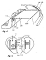
- FIG. 4 shows a second embodiment of a roller blind system according to the invention.
- This in turn is arranged in the rear region of a vehicle and in turn has a cassette housing 110 in which a roller shaft 120 is rotatably mounted in a manner not shown in detail.
- a sheet 130 is wound, which in Fig. 4 in the vehicle longitudinal direction to the rear of the roller shaft 120 is unwound.
- a support rod 132 is provided which extends laterally with extensions 132a over the sheet.
- Guide rails 140 are provided on the D pillars 148 of the vehicle.
- the cassette housing 110 is removable.
- vehicle-mounted seats 114 are provided on both sides of the cassette housing.
- the cartridge housing 110 can be inserted from above.
- a motor 112 for driving the roller shaft 120 is accommodated in the left-side receptacle 114 instead of the cartridge case 110.
- FIG. 5 shows the coupling portion between this left-side receiving device 114 and the cassette housing 110.
- the receiving device 114 shown on the left contains the electric motor 112, the output shaft 112a of which is led out towards the center of the vehicle out of the housing of the receiving device 114 and is provided there with a toothed wheel 112b.
- an approximately U-shaped web 118 is provided on this side of the receiving device 114.
- front end of the cassette housing 110 also webs 110a provided between which also a gear 111 is arranged.
- This gear 111 is rotatably connected by means of a shaft 111 a with the roller shaft 120 within the cassette housing 110.
- the cassette housing 110 can be inserted in the direction of the arrow 4 from above into the space defined by the U-shaped web 118 of the receiving device 114, wherein the two gears 111, 112b engage with each other.
- torque may be transmitted from the motor 112 within the receptacle 114 to the roller shaft 120 within the cartridge housing 110.
- the guide rail 140 is, as in the FIGS. 6a, 6b and 7 is formed as part of an integral assembly 190.
- This has a plastic housing 192, in which the groove 140 is integrally provided.
- the groove 140 transitions into an insertion region 140c, into which the extension 132a of the end-side support rod 132 of the fabric 130 can be inserted.
- a carriage 150 is arranged in the groove 140. Deviating from the embodiment of FIGS. 1 to 3 However, this carriage 150 to limit the mobility of the extensions 132, only one stop surface 152a.
- the abutment surface 150a is integrally connected to a cable pull holder 154.
- a cable pull 160 attached to the cable puller 154 is like the rear view of the FIG. 6b shows, connected to a spring motor 162, which is provided directly on the assembly 190.
- an additional retaining pawl 180 is provided at the lower end 140b of the groove 140. This holding pawl is acted upon by a force provided on the rear side spring 182. As a result, an additional securing of the extensions 132a in the lower end position can be achieved.
Description
Die Erfindung betrifft ein Rollosystem für ein Fahrzeug, insbesondere zur Abdeckung eines Heckstauraums des Fahrzeugs, mit einer drehbar gelagerten Rollowelle, einem auf der Rollowelle aufgewickelten und in eine Abwickelrichtung abwickelbaren flexiblen Flächengebilde und einer Aufnahmevorrichtung zur Festlegung eines der Rollowelle abgewandten distalen Endes des flexiblen Flächengebildes in einem zumindest teilweise abgewickelten Zustand.The invention relates to a roller blind system for a vehicle, in particular for covering a rear stowage space of the vehicle, with a rotatably mounted roller blind shaft, a wound on the roller blind and unwindable in a unwinding flexible sheet and a receiving device for fixing a blind shaft remote from the distal end of the flexible sheet in an at least partially completed state.
Gattungsgemäße Rollosysteme sind aus dem Stand der Technik bekannt. Sie werden insbesondere als Laderaumabdeckung genutzt, die verhindern, dass von außerhalb des Fahrzeugs in den Gepäckbereich des Fahrzeugs Einblick genommen werden kann. Andere Anwendungsfelder sind die Verwendung als Trennnetz oder Sonnenschutzblenden.Generic shade systems are known from the prior art. They are used, in particular, as cargo compartment covers, which prevent the possibility of being viewed from outside the vehicle in the luggage area of the vehicle. Other fields of application are the use as a separation net or sun visor.
Bei den aus dem Stand der Technik bekannten Rollosystemen ist vorgesehen, dass das Flächengebilde mittels eines Federmittels aufgerollt wird. Dieses Federmittel liegt zumeist in Form einer Wickelfeder vor, die ein Rückholmoment auf die Rollowelle ausübt. Das abgezogene Flächengebilde wird dadurch mit einer Rückholkraft beaufschlagt, die das Flächengebilde in den aufgewickelten Stauzustand zurückzieht. Um zu verhindern, dass das Flächengebilde durch das Rückholmoment ungewollt wieder aufgerollt wird, wird es in einem Funktionszustand gesichert, indem ein distales Ende des Flächengebildes mittels dafür vorgesehener Aufnahmevorrichtungen festgelegt wird.In the roller blind systems known from the prior art it is provided that the fabric is rolled up by means of a spring means becomes. This spring means is usually in the form of a coil spring, which exerts a Rückholomoment on the roller shaft. The stripped sheet is thereby subjected to a return force which retracts the sheet into the wound up state. In order to prevent the sheet being unintentionally rewound by the return spring moment, it is secured in a functional state by fixing a distal end of the sheet by means of receiving devices provided therefor.
Weiterhin ist aus dem Stand der Technik bekannt, beispielsweise aus der
Als nachteilig hieran wird angesehen, dass es nicht ohne weiteres möglich ist, mit nur einem Elektromotor auszukommen. Zwar zeigt die
Aufgabe der Erfindung ist es daher, ein gattungsgemäßes Rollosystem für ein Fahrzeug dahingehend weiterzubilden, dass mit einem geringen Aufwand eine zuverlässige elektromotorische Steuerung des Flächengebildes ermöglicht wird.The object of the invention is therefore to develop a generic shade system for a vehicle to the effect that with a low cost, a reliable electromotive control of the fabric is made possible.
Erfindungsgemäß wird dies durch ein Rollosystem gemäß dem Anspruch 1 erreicht, wobei ein Elektromotor zum Antrieb der Rollowelle vorgesehen ist.According to the invention this is achieved by a roller blind system according to claim 1, wherein an electric motor is provided for driving the roller shaft.
Somit wird direkt die Rollowelle durch den Elektromotor angetrieben. Je nach Drehrichtung gibt der Elektromotor das flexible Flächengebilde von der Rollowelle frei oder wickelt es auf dieser auf. Der Elektromotor kann unmittelbar mittels dafür vorgesehener Schalter, beispielsweise im Kofferraumbereich, gesteuert werden. Andere Ausführungsformen sehen vor, dass der Motor durch ein Steuergerät gesteuert wird, welches anhand weiterer Daten, wie beispielsweise dem Öffnungszustand einer Heckklappe, automatisch die Steuerung des Elektromotors übernimmt. Vorzugsweise findet ein Elektromotor Anwendung, der ein Rastmoment bei fehlender Bestromung aufweist, welches verhindert, dass das abgewickelte und durch die Aufnahmevorrichtung gesicherte Flächengebilde durchhängt. Die Rollowelle ist vorzugsweise in einem Kassettengehäuse angeordnet, wobei der Elektromotor innerhalb oder außerhalb dieses Kassettengehäuses vorgesehen sein kann.Thus, the roller blind shaft is directly driven by the electric motor. Depending on the direction of rotation of the electric motor releases the flexible sheet of the roller shaft or winds it on this. The electric motor can be controlled directly by means of dedicated switches, for example in the boot area. Other embodiments provide that the engine is controlled by a control unit, which automatically takes over the control of the electric motor based on further data, such as the opening state of a tailgate. Preferably, an electric motor is used, which has a cogging torque in the absence of energization, which prevents the unwound and secured by the receiving device sags. The roller shaft is preferably arranged in a cassette housing, wherein the electric motor can be provided inside or outside of this cassette housing.
Nachfolgend werden Weiterbildungen in Hinblick auf eine Aufnahmevorrichtung erläutert. Es ist allerdings bevorzugt, dass zwei identische oder weitgehend identische, spiegelbildlich beidseitig des Flächengebildes vorgesehene Aufnahmevorrichtungen vorgesehen sind.In the following, developments with regard to a receiving device will be explained. However, it is preferred that two identical or largely identical recording devices provided on both sides of the sheet in mirror image form are provided.
Die Aufnahmevorrichtung weist mindestens einen beweglichen Anschlag auf, der durch eine Federkraft eines Federmittels in Richtung der Abwickelrichtung kraftbeaufschlagt ist. Durch diese Federkraft wird das flexible Flächengebilde in Richtung seines abgewickelten Zustandes gezogen. Die Wirkung ist, dass das Flächengebilde gespannt wird und ein Durchhängen verhindert wird. Wenn durch den Elektromotor ein zusätzlicher Teil des Flächengebildes von der Rollowelle abgewickelt wird, werden durch das Federmittel und den Anschlag, der korrespondierend mit dem Flächengebilde mitbewegt wird, der gespannte Zustand aufrechterhalten. Wenn durch den Elektromotor das Flächengebilde oder ein Teil davon auf der Rollowelle aufgewickelt wird, so wird das Federmittel aufgrund der Bewegung des Anschlags weiter ausgelenkt und dadurch zusätzlich gespannt. Die Federkraft des Federmittels ist dabei so bemessen, dass sie stets geringer ist als die durch den Elektromotor aufbringbare Motorkraft, sodass die Motorkraft des Elektromotors die entgegengesetzte Federkraft stets überwinden kann. Die Federkraft ist jedoch ausreichend groß, um das Flächengebilde in einem optisch einwandfrei gespannten Zustand zu halten. Als beweglicher Anschlag im Sinne der Erfindung wird eine jede Vorrichtung angesehen, die mit dem distale Ende des Flächengebildes oder einem ihm fest zugeordneter Abschnitt derart wechselwirkt, dass sie durch das elektromotorische Aufwickeln des Flächengebildes unter Erhöhung der Spannung des Federmittels ausgelenkt wird. Unter der Kraftbeaufschlagung in Richtung der Abwickelrichtung wird im Zusammenhang mit dieser Erfindung verstanden, dass die Auslenkung des Federmittels beim Aufwickeln des Flächengebildes zunimmt und beim Abwickeln des Flächengebildes abnimmt, so dass die Kraftbeaufschlagung durch das Federmittel stets so gerichtet ist, dass sie ein Spannen des Flächengebildes bewirkt.The receiving device has at least one movable stop, which is acted upon by a spring force of a spring means in the direction of the unwinding direction. By this spring force, the flexible fabric is pulled in the direction of its unwound state. The effect is that the fabric is stretched and sagging is prevented. When an additional part of the sheet is unwound from the roller shaft by the electric motor, the tensioned state is maintained by the spring means and the stop which is moved in correspondence with the sheet. If by the electric motor, the sheet or a part thereof is wound on the roller shaft, so the spring means is further deflected due to the movement of the stop and thereby additionally stretched. The spring force of the spring means is so dimensioned that it is always lower than the motor motor applied by the electric motor, so that the engine power of the electric motor can always overcome the opposite spring force. However, the spring force is sufficiently large to hold the sheet in a visually properly tensioned state. As a movable stop in the context of the invention, any device is considered, which interacts with the distal end of the sheet or a fixedly assigned portion such that it is deflected by the electromotive winding of the sheet under increasing the tension of the spring means. Under the application of force in the direction of the unwinding direction is understood in the context of this invention that the deflection of the spring means increases during winding of the fabric and decreases during unwinding of the fabric, so that the application of force by the spring means is always directed so that it is a tensioning of the fabric causes.
Vorzugsweise weist die Aufnahmevorrichtung mindestens eine Führungsschiene auf. Die Führungsschiene ist bei einer möglichen Ausgestaltung dafür vorgesehen, einen Fortsatz am distalen Ende des flexiblen Flächengebildes unmittelbar aufzunehmen. Alternativ kann das distale Ende des flexiblen Flächengebildes oder ein daran vorgesehener Fortsatz an einem Führungsschlitten befestigt werden, der seinerseits in der Führungsschiene gelagert ist und durch diese geführt wird. Vorzugsweise dient die Führungsschiene darüber hinaus der Aufnahme des beweglichen Anschlags. Insbesondere kann die Führungsschiene als Nut ausgebildet sein, in die ein Fortsatz des flexiblen Flächengebildes eingreift und/oder in der der Anschlag beweglich geführt ist.Preferably, the receiving device has at least one guide rail. The guide rail is provided in a possible embodiment for directly receiving an extension at the distal end of the flexible sheet. Alternatively, the distal end of the flexible sheet or a projection provided thereon can be secured to a guide carriage, which in turn is mounted in the guide rail and is guided by it. Preferably, the guide rail also serves to receive the movable stop. In particular, the guide rail may be formed as a groove, in which engages an extension of the flexible sheet and / or in which the stop is movably guided.
Eine besonders einfache Ausgestaltung sieht vor, dass die Führungsschiene fluchtend zur Rollowelle verläuft. Dies ist beispielsweise als besonders einfache Variante für Laderaumabdeckungen verwendbar. Die Führungsschiene ist dabei vorzugsweise bezüglich ihrer Länge derart ausgelegt, dass das flexible Flächengebilde stets innerhalb der Führungsschiene verbleiben kann. Ihre Länge entspricht dabei mindestens der Strecke, um die das distale Ende des Flächengebildes zwischen einem aufgewickelten Stauzustand und abgewickelten Funktionszustand bewegbar ist. Das distale Ende des Flächengebildes ist somit sowohl im kompakten Stauzustand als auch im abgewickelten Funktionszustand durch die Führungsschiene geführt.A particularly simple embodiment provides that the guide rail extends in alignment with the roller blind shaft. This is for example as special simple variant usable for load compartment covers. The guide rail is preferably designed with respect to its length such that the flexible sheet can always remain within the guide rail. Their length corresponds to at least the distance by which the distal end of the sheet is movable between a wound-up state and a state of unwound state. The distal end of the fabric is thus guided through the guide rail both in the compact storage state and in the unwound functional state.
Alternativ verläuft die Führungsschiene zumindest abschnittsweise nicht fluchtend zur Rollowelle. Dies gestattet es, Komfortfunktionen zu realisieren, wie beispielsweise im Falle einer Laderaumabdeckung einen Zustand mit angehobenem distalen Endes des Flächengebildes, um bequemen Zugang zu dem darunter liegenden Gepäck zu ermöglichen. Vorzugsweise ist die Führungsschiene demnach in einer das Fahrzeug heckseitig abschließenden Fahrzeugsäule, insbesondere einer C-Säule oder einer D-Säule angeordnet. Bei einer solchen Ausgestaltung wird es zudem als vorteilhaft angesehen, wenn die Schiene nicht zur Aufnahme des flexiblen Flächengebildes in seinem Stauzustand vorgesehen ist. Stattdessen ist die Führungsschiene vorzugsweise vollständig von der Rollowelle beabstandet, sodass die bestimmungsgemäße Funktionsweise vorsieht, dass das Flächengebilde zunächst von der Rollowelle abgezogen oder durch den Elektromotor abgewickelt wird und erst anschließend in die Führungsschiene eingesetzt wird.Alternatively, the guide rail is at least partially not aligned with the roller shaft. This makes it possible to realize comfort functions, such as in the case of a luggage compartment cover, a condition with raised distal end of the fabric to allow easy access to the underlying luggage. The guide rail is therefore preferably arranged in a vehicle column terminating the vehicle at the rear, in particular a C-pillar or a D-pillar. In such an embodiment, it is also considered advantageous if the rail is not provided for receiving the flexible sheet in its storage condition. Instead, the guide rail is preferably completely spaced from the roller blind, so that the intended operation provides that the fabric is first subtracted from the roller shaft or unwound by the electric motor and only then used in the guide rail.
Vorzugsweise ist der bewegliche Anschlag im Bereich der Führungsschiene vorgesehen, so dass das distale Ende des flexiblen Flächengebildes nur dann durch diesen Anschlag kraftbeaufschlagt wird, wenn es in die Führungsschiene eingesetzt ist. Das distale Ende des Flächengebildes kann demnach unabhängig vom Anschlag frei gehandhabt werden, bis es in die Führungsschiene oder einen daran vorgesehenen Schlitten eingesetzt wird. Erst dann entfaltet der federbelastete Anschlag seine Wirkung.Preferably, the movable stop is provided in the region of the guide rail, so that the distal end of the flexible sheet is subjected to force only by this stop when it is inserted into the guide rail. The distal end of the sheet can thus be handled independently of the stop, until it is in the guide rail or provided thereon Carriage is used. Only then does the spring-loaded stop unfold its effect.
An der Führungsschiene ist vorzugsweise zusätzlich mindestens ein weiteres Festlegungsmittel vorgesehen, vorzugsweise eine auslenkbare Halteklinke. Dieses zusätzliche Festlegungsmittel erlaubt es, das distale Ende des flexiblen Flächengebildes in einem definierten Funktionszustand zusätzlich zu sichern. Bei einem bestimmungsgemäßen Rollosystem, dessen Führungsschiene in der D-Säule eines Kombifahrzeugs verläuft und bei ähnlichen Anwendungsfeldern, bei denen Laderaumabdeckungen mit einer oben beschriebenen Komfortfunktion Anwendung finden, kann eine solche zusätzliche Sicherung vorzugsweise in einer Horizontallage des Flächengebildes vorgesehen sein. Durch das zusätzlichen Festlegungsmittel kann beispielsweise erreicht werden, dass Erschütterungen während der Fahrt des Fahrzeugs nicht dazu führen, dass das distale Ende des Flächengebildes entgegen der Federkraft des Federmittels ausgelenkt wird. Auch eine unangenehme Geräuschentwicklung kann hierdurch verhindert werden.At least one further fixing means is preferably provided on the guide rail, preferably a deflectable holding pawl. This additional fixing means makes it possible to additionally secure the distal end of the flexible sheet in a defined functional state. In a designated roller blind system, the guide rail extends in the D-pillar of a combined vehicle and similar application fields where load compartment covers with a comfort feature described above application, such additional backup may preferably be provided in a horizontal position of the fabric. By the additional fixing means can be achieved, for example, that vibrations during driving of the vehicle do not cause the distal end of the sheet is deflected against the spring force of the spring means. Even an unpleasant noise can be prevented.
Als Federmittel wird ein Federmotor verwendet, wobei die Federkraft vom Federmotor mittels eines Seilzugs auf den beweglichen Anschlag übertragen wird. Der Seilzug gestattet dabei eine besonders flexible Anordnung des Federmotors. Vorzugsweise ist der Anschlag in einer Nut der Führungsschiene verschieblich vorgesehen, wobei es als besonders vorteilhaft angesehen wird, wenn diese Nut in ihrem Nutgrund eine der Nutrichtung folgende Durchbrechung aufweist, mittels der der Anschlag geführt und/oder mit dem Seilzug verbunden werden kann. Alternativ kann der Seilzug auch in der Nut selbst geführt werden.As spring means a spring motor is used, wherein the spring force is transmitted by the spring motor by means of a cable to the movable stop. The cable allows a particularly flexible arrangement of the spring motor. Preferably, the stop is slidably provided in a groove of the guide rail, wherein it is considered to be particularly advantageous if this groove in its groove bottom has a groove following the opening, by means of which the stop out and / or can be connected to the cable. Alternatively, the cable can also be guided in the groove itself.
Als besonders vorteilhaft wird es angesehen, wenn die Aufnahmevorrichtung mit der Führungsschiene, dem beweglichen Anschlag sowie dem Federmittel als Vormontageeinheit ausgebildet ist. Als Vormontageeinheit im Sinne dieser Erfindung wird die Aufnahmevorrichtung angesehen, wenn die genannten Bauteile zunächst miteinander verbunden werden können, bevor sie in ihrer Gesamtheit im Fahrzeug montiert werden. Eine solche Vormontageeinheit ist in Hinblick auf eine einfache und schnelle Fahrzeugfertigung gewünscht. Die Befestigung der Vormontageeinheit am Fahrzeug erfolgt vorzugsweise durch eine Festlegung der Führungsschiene oder eine Festlegung von mit der Führungsschiene verbundenen Befestigungsabschnitten am Fahrzeug. Besonders bevorzugt ist es, wenn ein die verschiedenen Bauelemente aufnehmendes Chassis vorgesehen ist, in welchem die Führungsschiene vorzugsweise einstückig vorgesehen ist.It is considered to be particularly advantageous if the receiving device with the guide rail, the movable stop and the spring means is designed as a pre-assembly unit. As pre-assembly in the sense of this invention, the receiving device is considered when said components can first be interconnected before being assembled in their entirety in the vehicle. Such a preassembly unit is desired in view of a simple and fast vehicle production. The attachment of the pre-assembly on the vehicle is preferably carried out by a determination of the guide rail or a determination of the guide rail connected to the mounting portions on the vehicle. It is particularly preferred if a chassis accommodating the various components is provided, in which the guide rail is preferably provided in one piece.
Bei einer besonders bevorzugten Ausgestaltung ist die Rollowelle werkzeuglos aus einer fahrzeugfesten Rollowellenaufnahme entfernbar und in diese fahrzeugfeste Rollowellenaufnahme einsetzbar, wobei der Elektromotor fahrzeugfest vorgesehen ist. Durch diese Gestaltung wird ein Entnehmen und Einsetzen der Rollowelle möglich, ohne das hierbei elektrische Verbindung zu beachten sind. Die Rollowelle, die vorzugsweise in einem gemeinsam mit der Rollowelle entnehmbaren Kassettengehäuse gelagert ist, wird beim Entfernen aus der Rollowellenaufnahme gleichzeitig auch mechanisch vom Elektromotor des Antriebs getrennt. Dieser verbleibt fest im Fahrzeug montiert. Er ist dabei vorzugsweise unmittelbar an oder in der Rollowellenaufnahme vorgesehen. Die Gestaltung der Rollowelle als werkzeuglos entnehmbare Rollowelle erhöht die Flexibilität des Fahrzeugs, da durch das Entfernen Platz gewonnen werden kann. Als Rollowellenaufnahme im Sinne dieser Weiterbildung wird auch eine Aufnahme eines Kassettengehäuses angesehen, innerhalb dessen die Rollowelle gelagert ist.In a particularly preferred embodiment, the roller blind shaft is removable without tools from a vehicle-fixed roller blind receptacle and can be used in this vehicle-mounted roller blind receptacle, wherein the electric motor is fixed to the vehicle. This design makes it possible to remove and insert the roller blind shaft without the need for electrical connection. The roller shaft, which is preferably mounted in a detachable with the roller shaft cassette housing, is simultaneously separated mechanically from the electric motor of the drive when removing from the roller blind. This remains firmly mounted in the vehicle. He is preferably provided directly on or in the Rollowellenaufnahme. The design of the roller blind as a tool-free removable roller shaft increases the flexibility of the vehicle, since the removal can be gained space. As Rollowellenaufnahme in the sense of this development, a recording of a cassette housing is considered, within which the roller blind shaft is mounted.
Zwischen dem Elektromotor und einer Antriebswelle der Rollowelle, die auch mit der Rollowelle identisch sein kann, ist vorzugsweise eine formschlüssig wirkende Kupplung vorgesehen. Diese Kupplung kann beispielsweise axial kuppelbar sein, sodass es nach Einsetzen der Rollowelle vorgesehen ist, diese zunächst axial zu verschieben, um den Formschluss herzustellen. Eine bevorzugte Ausgestaltung sieht jedoch vor, dass diese Kupplung zwei im eingesetzten Zustand der Rollowelle miteinander kämmende Zahnräder umfasst, von denen eines mittelbar oder unmittelbar am Elektromotor vorgesehen ist und das andere an der Antriebswelle der Rollowelle vorgesehen ist. Das rollowellenseitige Zahnrad ist vorzugsweise unmittelbar auf der Rollowelle vorgesehen. Durch das Einsetzen der Rollowelle in die Rollowellenaufnahme werden die Zahnräder in Eingriff miteinander gebracht, sodass nachfolgend eine Betätigung der Rollowelle mittels des Elektromotors möglich ist.Between the electric motor and a drive shaft of the roller shaft, which may also be identical to the roller shaft, a positive-acting coupling is preferably provided. This coupling can be axially coupled, for example, so that it is provided after the onset of the roller shaft, these first to move axially to the Form fit. A preferred embodiment provides, however, that this clutch comprises two meshing with each other in the inserted state of the roller blind gears, one of which is provided directly or indirectly on the electric motor and the other is provided on the drive shaft of the roller blind. The rollowellenseitige gear is preferably provided directly on the roller shaft. By inserting the roller shaft into the roller blind receiving the gears are brought into engagement with each other, so that subsequently an operation of the roller shaft by means of the electric motor is possible.
Die Rollowelle selbst weist vorzugsweise einen radialen Aufnahmeschlitz zum Einlegen des flexiblen Flächengebildes auf. Aufgrund der Tatsache, dass keine Wickelfeder oder ähnliches innerhalb der Rollowelle erforderlich ist, kann eine sehr dünne Gestaltung der Rollowelle vorgesehen werden. Die Festlegung des Flächengebildes an der Rollowelle kann im einfachsten Fall durch den radialen Aufnahmeschlitz realisiert werden, durch den das Flächengebilde hindurchgeschoben wird, bevor es dann auf der Rollowelle aufgewickelt wird.The roller blind itself preferably has a radial receiving slot for insertion of the flexible sheet. Due to the fact that no coil spring or the like is required within the roller shaft, a very thin design of the roller blind shaft can be provided. The determination of the sheet to the roller shaft can be realized in the simplest case by the radial receiving slot through which the sheet is pushed before it is then wound up on the roller shaft.
Weitere Merkmale und Vorteile der Erfindung ergeben sich außer aus den Ansprüchen auch aus der nachfolgenden Beschreibung bevorzugter Ausführungsbeispiele der Erfindung. Diese sind anhand der Figuren erläutert. Dabei zeigen:
- Figur 1
- den Heckbereich eines Fahrzeugs mit einer ersten Ausführungsform eines erfindungsgemäßen Rollosystems,
Figur 2- eine Führungsschiene, ein in die Führungsschiene einsetzbarer Schlitten sowie das distale Ende eines Flächengebildes des Rollosystems der
Figur 1 , - Figur 3
- eine schematische Darstellung der Führungsschiene sowie des Federmotors der Ausführungsform der Figur 1,
Figur 4- der Heckbereich eines Fahrzeugs mit einer zweiten Ausführungsform eines erfindungsgemäßen Rollosystems,
- Figur 5
- die Kupplung zwischen einer fahrzeugfesten Aufnahme eines Kassettengehäuses sowie einem Kassettengehäuse der Ausführungsform der
Figur 4 , - Figur 6a und 6b
- eine Vorderansicht sowie eine Rückansicht einer Führungsschienen-Baueinheit der Ausführungsform der
Figur 4 und - Figur 7
- die Führungsschiene, ein in die Führungsschiene einsetzbarer Anschlag sowie das distale Ende eines Flächengebildes des Rollosystems der
Figur 4
- FIG. 1
- the rear area of a vehicle with a first embodiment of a roller blind system according to the invention,
- FIG. 2
- a guide rail, an insertable into the guide rail carriage and the distal end of a sheet of the roller blind system of
FIG. 1 . - FIG. 3
- 1 is a schematic representation of the guide rail and of the spring motor of the embodiment of FIG. 1,
- FIG. 4
- the rear area of a vehicle with a second embodiment of a roller blind system according to the invention,
- FIG. 5
- the coupling between a vehicle-mounted receptacle of a cassette housing and a cassette housing of the embodiment of the
FIG. 4 . - FIGS. 6a and 6b
- a front view and a rear view of a guide rail assembly of the embodiment of the
FIG. 4 and - FIG. 7
- the guide rail, an insertable into the guide rail stop and the distal end of a sheet of the roller blind system of
FIG. 4 ,
Das Rollosystem weist als wesentliche Komponenten ein fahrzeugfest montiertes Kassettengehäuse 10 auf, innerhalb dessen eine Rollowelle 20 drehbar gelagert ist. Auf der Rollowelle 20 ist ein flexibles Flächengebilde 30 aufgewickelt, welches in der Darstellung der
In dem ausgezogenen Zustand der
Die für diese Kopplung vorgesehenen Bauteile sind in der
In der
Bezugnehmend auf die
Sobald, beispielsweise nach Einladen von Gepäck in den Laderaum des Fahrzeugs, durch den Motor 12 die Rollowelle wieder in entgegengesetzte Richtung gedreht wird und dadurch der zuvor aufgewickelte Teil des Flächengebildes 30 wieder abgewickelt wird, wird der Schlitten 50 durch den Federmotor 62 und die darin gespeicherte Energie zurück in Richtung 2 gezogen. Das Flächengebilde nimmt wieder die in
Das dargestellte Rollosystem zeichnet sich vor allem dadurch aus, dass der Elektromotor an der Rollowelle 30 vorgesehen ist, wo ausreichend Platz vorhanden ist. Im hinteren Bereich des Fahrzeugs an den Aufnahmevorrichtungen mit den Führungsschienen 40 ist dagegen nur der baulich sehr unaufwändige Federmotor 62 erforderlich.The roller blind system shown is characterized in particular by the fact that the electric motor is provided on the
Die Unterschiede zwischen der Ausführungsform der
Abweichend von der Ausgestaltung der
Die Führungsschiene 140 ist, wie in den
Ebenfalls abweichend von der Ausgestaltung der
Die Funktionsweise entspricht der Ausführungsform der
Claims (8)
- Roller blind system for a vehicle, in particular for covering a rear luggage compartment of a vehicle, having- a roller blind shaft (20; 120) rotatably mounted inside a vehicle,- a flexible planar structure (30; 130) wound onto the roller blind shaft (20; 120) and unwindable in an unwinding direction, and- a receiving device (40; 140, 190) for fixing of a distal end (30a; 130a) of the textile planar structure (30; 130), said end facing away from the roller blind shaft (20; 120), in an at least partially wound state,where- an electric motor (12; 112) is provided to drive the roller blind shaft (20; 120)characterized in that
the receiving device (40; 140, 190) has at least one movable stop (52a; 152a) subjected to force in the unwinding direction by a spring force of a spring motor (62; 162) and by a pull cable (60; 160). - Roller blind system according to claim 1,
characterized in that
the receiving device (40; 140, 190) has at least one guide rail (40; 140). - Roller blind system according to claim 2,
characterized in that
the guide rail runs in alignment with the roller blind shaft. - Roller blind system according to claim 2,
characterized in that
the guide rail (40; 140) runs at least in some sections out of alignment with the roller blind shaft (30; 130). - Roller blind system according to one of claims 2 to 4,
characterized in that
the guide rail (40; 140) is designed as a guide groove (40; 140), the movable stop (52a; 152a) being arranged inside the guide groove. - Roller blind system according to one of claims 2 to 5,
characterized in that
at least one additional fixing means (180), preferably an adjustable retaining catch (180), is provided on the guide rail (140). - Roller blind system according to one of claims 2 to 6,
characterized in that
the receiving device (190) with the guide rail (140), the movable stop (152a) and the spring motor (162) is designed as a preassembled unit (190). - Roller blind system according to one of the preceding claims,
characterized in that
the roller blind shaft (130) has a radial receiving slot for insertion of the flexible planar structure.
Applications Claiming Priority (1)
| Application Number | Priority Date | Filing Date | Title |
|---|---|---|---|
| DE102007057074A DE102007057074A1 (en) | 2007-11-23 | 2007-11-23 | window treatment |
Publications (2)
| Publication Number | Publication Date |
|---|---|
| EP2062780A1 EP2062780A1 (en) | 2009-05-27 |
| EP2062780B1 true EP2062780B1 (en) | 2010-06-02 |
Family
ID=40280774
Family Applications (1)
| Application Number | Title | Priority Date | Filing Date |
|---|---|---|---|
| EP20080018456 Expired - Fee Related EP2062780B1 (en) | 2007-11-23 | 2008-10-22 | Roller blind system |
Country Status (3)
| Country | Link |
|---|---|
| EP (1) | EP2062780B1 (en) |
| CN (1) | CN101439693B (en) |
| DE (2) | DE102007057074A1 (en) |
Families Citing this family (11)
| Publication number | Priority date | Publication date | Assignee | Title |
|---|---|---|---|---|
| DE102010020657B4 (en) | 2010-05-05 | 2015-01-08 | Bos Gmbh & Co. Kg | Roller blind system for a vehicle interior |
| DE102010052743B4 (en) * | 2010-11-26 | 2016-10-27 | Audi Ag | Motor vehicle with tool-free removable component and parcel shelf for a motor vehicle |
| JP2012206675A (en) | 2011-03-30 | 2012-10-25 | Tokai Rika Co Ltd | Tonneau cover device |
| DE102012202293A1 (en) * | 2012-02-15 | 2013-08-22 | Brose Fahrzeugteile Gmbh & Co. Kommanditgesellschaft, Coburg | Adjustment device for a load compartment cover |
| JP6329180B2 (en) * | 2013-02-21 | 2018-05-23 | トヨタ モーター ヨーロッパ | Tonneau cover device and system for vehicle |
| DE102013017104A1 (en) * | 2013-10-15 | 2015-04-30 | GM Global Technology Operations, LLC (n.d. Ges. d. Staates Delaware) | Trunk cover and vehicle with the trunk cover |
| DE102015118305A1 (en) * | 2015-10-01 | 2017-04-06 | Fkt Gmbh | Separating device for a loading space of a motor vehicle |
| DE102016215599B3 (en) * | 2016-08-19 | 2017-07-27 | Bos Gmbh & Co. Kg | Protective device for a vehicle interior |
| CN108146352B (en) * | 2017-12-26 | 2021-04-23 | 重庆程顺汽车配件制造有限公司 | Be used for vapour car trunk fixing device |
| FR3096631B1 (en) * | 2019-05-31 | 2021-11-12 | Inteva Products France Sas | MOTORIZED VEHICLE LUGGAGE COVER |
| CN117601770A (en) * | 2024-01-24 | 2024-02-27 | 宁波帅特龙集团有限公司 | Electric curtain for vehicle |
Family Cites Families (5)
| Publication number | Priority date | Publication date | Assignee | Title |
|---|---|---|---|---|
| EP0866208A3 (en) * | 1997-03-20 | 2001-02-14 | Robert Goyvaerts | Roller Shutter |
| US6086133A (en) * | 1998-04-06 | 2000-07-11 | Alonso; Miguel | Vehicle window shade arrangement |
| DE19944948C1 (en) | 1999-09-20 | 2001-05-31 | Baumeister & Ostler Gmbh Co | Protection device for an interior of a motor vehicle |
| DE10229675B4 (en) * | 2002-06-27 | 2005-06-09 | Bos Gmbh & Co. Kg | Locking device for a motor vehicle |
| DE10330627B4 (en) * | 2003-07-07 | 2006-08-03 | Bos Gmbh & Co. Kg | Load compartment cover with self-running pull-out profile |
-
2007
- 2007-11-23 DE DE102007057074A patent/DE102007057074A1/en not_active Withdrawn
-
2008
- 2008-10-22 DE DE200850000740 patent/DE502008000740D1/en active Active
- 2008-10-22 EP EP20080018456 patent/EP2062780B1/en not_active Expired - Fee Related
- 2008-11-24 CN CN 200810182164 patent/CN101439693B/en not_active Expired - Fee Related
Also Published As
| Publication number | Publication date |
|---|---|
| DE102007057074A1 (en) | 2009-06-04 |
| CN101439693A (en) | 2009-05-27 |
| CN101439693B (en) | 2013-02-06 |
| DE502008000740D1 (en) | 2010-07-15 |
| EP2062780A1 (en) | 2009-05-27 |
Similar Documents
| Publication | Publication Date | Title |
|---|---|---|
| EP2062780B1 (en) | Roller blind system | |
| EP1740426B1 (en) | Roller blind system for a vehicle roof | |
| EP1666291B1 (en) | Window roller blind with simplified assembly | |
| EP1389544B1 (en) | Roller blind with coupling mechanism | |
| WO2006034690A1 (en) | Blind arrangement for a motor vehicle | |
| EP1967401A2 (en) | Automatic side door roller blind | |
| DE102007012259A1 (en) | Sun protection roller blind for motor vehicles | |
| EP1418073A1 (en) | Roller blind with lid on the extract slot | |
| DE102011113207B4 (en) | Vehicle blind arrangement and vehicle roof | |
| DE102013110650A1 (en) | Arrangement for a roller blind | |
| EP1626152A1 (en) | Solar protection device for glass roof | |
| EP1747923A2 (en) | Window roller blind with non-profiled thrust members | |
| DE102007057073B4 (en) | Cover system for a vehicle | |
| DE19750715C1 (en) | Roller shutter for motor vehicle roof | |
| DE102006035632B4 (en) | Roller blind arrangement for a vehicle roof | |
| DE19834777C2 (en) | Roller blind, in particular sun protection roller blind for the transparent roof window of a motor vehicle | |
| DE102008063775A1 (en) | Vehicle window roller blind comprises roller blind web for shading vehicle window with window frame, and winding unit for winding and unwinding roller blind web | |
| DE102006028353A1 (en) | Motor vehicle window blind, has gear wheel pivoted at two positions of rigid blind web end and gear wheel intervenes into gear rack fixed to vehicle and extending toward movement of roller web during winding and unwinding | |
| DE10215678B4 (en) | Shading device for a pane | |
| DE202007018359U1 (en) | window treatment | |
| DE202005011290U1 (en) | Blind to be positioned at lower surface of transparent sunroof, comprising transversally curved support bar | |
| EP0529591B1 (en) | Roller blind, preferably for vehicle rear windows | |
| WO2009033981A1 (en) | Adjustment device for a cover device in a motor vehicle | |
| DE102010018437A1 (en) | Winding device for roller blind arrangement of roof arrangement for car, has ranging member axially extending into cavity of spring and loosely arranged relative to winding element and bearing element, where ranging member guides spring | |
| DE10324545B4 (en) | Winding shaft with external spring drive |
Legal Events
| Date | Code | Title | Description |
|---|---|---|---|
| PUAI | Public reference made under article 153(3) epc to a published international application that has entered the european phase |
Free format text: ORIGINAL CODE: 0009012 |
|
| AK | Designated contracting states |
Kind code of ref document: A1 Designated state(s): AT BE BG CH CY CZ DE DK EE ES FI FR GB GR HR HU IE IS IT LI LT LU LV MC MT NL NO PL PT RO SE SI SK TR |
|
| AX | Request for extension of the european patent |
Extension state: AL BA MK RS |
|
| 17P | Request for examination filed |
Effective date: 20090701 |
|
| 17Q | First examination report despatched |
Effective date: 20090730 |
|
| GRAP | Despatch of communication of intention to grant a patent |
Free format text: ORIGINAL CODE: EPIDOSNIGR1 |
|
| AKX | Designation fees paid |
Designated state(s): DE FR SE |
|
| GRAS | Grant fee paid |
Free format text: ORIGINAL CODE: EPIDOSNIGR3 |
|
| GRAA | (expected) grant |
Free format text: ORIGINAL CODE: 0009210 |
|
| AK | Designated contracting states |
Kind code of ref document: B1 Designated state(s): DE FR SE |
|
| REF | Corresponds to: |
Ref document number: 502008000740 Country of ref document: DE Date of ref document: 20100715 Kind code of ref document: P |
|
| PG25 | Lapsed in a contracting state [announced via postgrant information from national office to epo] |
Ref country code: SE Free format text: LAPSE BECAUSE OF FAILURE TO SUBMIT A TRANSLATION OF THE DESCRIPTION OR TO PAY THE FEE WITHIN THE PRESCRIBED TIME-LIMIT Effective date: 20100602 |
|
| PLBE | No opposition filed within time limit |
Free format text: ORIGINAL CODE: 0009261 |
|
| STAA | Information on the status of an ep patent application or granted ep patent |
Free format text: STATUS: NO OPPOSITION FILED WITHIN TIME LIMIT |
|
| 26N | No opposition filed |
Effective date: 20110303 |
|
| REG | Reference to a national code |
Ref country code: DE Ref legal event code: R097 Ref document number: 502008000740 Country of ref document: DE Effective date: 20110302 |
|
| PGFP | Annual fee paid to national office [announced via postgrant information from national office to epo] |
Ref country code: FR Payment date: 20121113 Year of fee payment: 5 |
|
| REG | Reference to a national code |
Ref country code: FR Ref legal event code: ST Effective date: 20140630 |
|
| PG25 | Lapsed in a contracting state [announced via postgrant information from national office to epo] |
Ref country code: FR Free format text: LAPSE BECAUSE OF NON-PAYMENT OF DUE FEES Effective date: 20131031 |
|
| PGFP | Annual fee paid to national office [announced via postgrant information from national office to epo] |
Ref country code: DE Payment date: 20161026 Year of fee payment: 9 |
|
| REG | Reference to a national code |
Ref country code: DE Ref legal event code: R119 Ref document number: 502008000740 Country of ref document: DE |
|
| PG25 | Lapsed in a contracting state [announced via postgrant information from national office to epo] |
Ref country code: DE Free format text: LAPSE BECAUSE OF NON-PAYMENT OF DUE FEES Effective date: 20180501 |