EP2329747A2 - Tension device for curtain rope - Google Patents
Tension device for curtain rope Download PDFInfo
- Publication number
- EP2329747A2 EP2329747A2 EP10187398A EP10187398A EP2329747A2 EP 2329747 A2 EP2329747 A2 EP 2329747A2 EP 10187398 A EP10187398 A EP 10187398A EP 10187398 A EP10187398 A EP 10187398A EP 2329747 A2 EP2329747 A2 EP 2329747A2
- Authority
- EP
- European Patent Office
- Prior art keywords
- clamping
- support
- clamping part
- longitudinal axis
- holding part
- Prior art date
- Legal status (The legal status is an assumption and is not a legal conclusion. Google has not performed a legal analysis and makes no representation as to the accuracy of the status listed.)
- Granted
Links
Images


Classifications
-
- A—HUMAN NECESSITIES
- A47—FURNITURE; DOMESTIC ARTICLES OR APPLIANCES; COFFEE MILLS; SPICE MILLS; SUCTION CLEANERS IN GENERAL
- A47H—FURNISHINGS FOR WINDOWS OR DOORS
- A47H1/00—Curtain suspension devices
- A47H1/18—Other curtain suspension devices, e.g. wire, cord, springs
- A47H1/19—Devices for mounting the wire, cord, or the like
-
- E—FIXED CONSTRUCTIONS
- E06—DOORS, WINDOWS, SHUTTERS, OR ROLLER BLINDS IN GENERAL; LADDERS
- E06B—FIXED OR MOVABLE CLOSURES FOR OPENINGS IN BUILDINGS, VEHICLES, FENCES OR LIKE ENCLOSURES IN GENERAL, e.g. DOORS, WINDOWS, BLINDS, GATES
- E06B7/00—Special arrangements or measures in connection with doors or windows
- E06B7/28—Other arrangements on doors or windows, e.g. door-plates, windows adapted to carry plants, hooks for window cleaners
-
- E—FIXED CONSTRUCTIONS
- E06—DOORS, WINDOWS, SHUTTERS, OR ROLLER BLINDS IN GENERAL; LADDERS
- E06B—FIXED OR MOVABLE CLOSURES FOR OPENINGS IN BUILDINGS, VEHICLES, FENCES OR LIKE ENCLOSURES IN GENERAL, e.g. DOORS, WINDOWS, BLINDS, GATES
- E06B9/00—Screening or protective devices for wall or similar openings, with or without operating or securing mechanisms; Closures of similar construction
- E06B9/24—Screens or other constructions affording protection against light, especially against sunshine; Similar screens for privacy or appearance; Slat blinds
- E06B9/26—Lamellar or like blinds, e.g. venetian blinds
- E06B9/28—Lamellar or like blinds, e.g. venetian blinds with horizontal lamellae, e.g. non-liftable
- E06B9/30—Lamellar or like blinds, e.g. venetian blinds with horizontal lamellae, e.g. non-liftable liftable
- E06B9/32—Operating, guiding, or securing devices therefor
- E06B9/327—Guides for raisable lamellar blinds with horizontal lamellae
-
- E—FIXED CONSTRUCTIONS
- E06—DOORS, WINDOWS, SHUTTERS, OR ROLLER BLINDS IN GENERAL; LADDERS
- E06B—FIXED OR MOVABLE CLOSURES FOR OPENINGS IN BUILDINGS, VEHICLES, FENCES OR LIKE ENCLOSURES IN GENERAL, e.g. DOORS, WINDOWS, BLINDS, GATES
- E06B9/00—Screening or protective devices for wall or similar openings, with or without operating or securing mechanisms; Closures of similar construction
- E06B9/24—Screens or other constructions affording protection against light, especially against sunshine; Similar screens for privacy or appearance; Slat blinds
Definitions
- the invention relates to a tensioning device for tensioning a rope according to the preamble of claim 1, a fastening device in particular for fastening a tensioning device to a window frame according to claim 8 and a fastening device, in particular for fastening a tensioning device to a level base according to claim 13.
- This may be a fork wrench, which is attached to a designated flattened on both sides of the second clamping element for transmitting the torque.
- the DE 201 07 752 U1 shows a curtain clip with a connector which is connected to a mounting frame unit.
- the connector includes a female member and a male member.
- an internal thread is arranged, which cooperates with an external thread of the plug element.
- a ball head clasp is arranged, which is rotatably received in a ball socket bore of the mounting frame unit.
- a plug-in element axially arranged through hole a steel cable can be accommodated, which is fixed by means of a hold-down screw on the plug-in element. Therefore, a tool, for example an Allen wrench, is required for mounting the steel cable. Furthermore, the steel cable must be threaded into the through hole before it can be fixed with the hold-down screw.
- the plug-in element is to be held against the direction of rotation during the rotation of the bushing element in order not to be twisted together with the bushing element.
- the assembly and tension of the steel rope proves to be expensive in this curtain clip.
- a suspension cable device for curtains is shown.
- a carrying cable is held on both sides in the partial bore of a clamping sleeve by means of a clamping screw.
- the clamping screw is screwed into a sleeve-like fastening fitting, which is attached to a mounting bracket for fixing to a wall.
- the clamping screws on both ends of the support cable are screwed into the associated mounting bracket, so that the clamping sleeve are pushed more or less into the interior of Befest Trentsbescläge and the Carrying rope is stretched.
- the tension of the supporting cable can only be carried out with the aid of a tool.
- the implementation of the support cable is complicated by the clamping screws and the ferrules in the correct order and therefore not user-friendly.
- Object of the present invention is therefore to propose a cable saving device that is easy to clamp. Another goal is to set the rope without effort on the rope tensioning device. It is also an object to show a rope tensioning device which can be fixed to the same without damaging the ground.
- the object is achieved in a tensioning device for tensioning a rope according to the preamble of claim 1, characterized in that the first clamping part consists of two symmetrical clamping parts, which have a common cut surface and that on the first clamping part along the longitudinal axis a fürgangsöfftung is provided, which Receiving the rope is used and which is formed by the fact that at the two clamping parts in each case along the longitudinal axis a recess is provided. Due to the bipartite of the first clamping part, it is not necessary to thread the rope in a passage opening on the first clamping part, but the rope is inserted in a simple manner between the two clamping parts.
- clamping parts can be produced in simply executed one-piece injection molds, without subsequently a thread would have to be cut into the first clamping part.
- This form of production is inexpensive and can be carried out with high cycle rates.
- the inclusion of the rope in the first clamping part designed by the intended passage opening as very easy, as this is only inserted into the recess of the first clamping member and the second clamping member is placed over the first.
- the clamping effect of the first clamping member, which acts on the rope, is very good, since it acts along the entire longitudinal axis of the first clamping part.
- the second clamping member is rotatably supported about the longitudinal axis on the support.
- the erfmdungssiee clamping device has the advantage that can be done by the holder of the second clamping part on the support of the tensioning process of the rope with one hand. This can be attributed to the fact that the tensioning part, which is held by the support, is only to be twisted during the tensioning process and can no longer be held manually until the threads of the two tensioning parts are in operative connection with one another.
- the tensioning device is suitable for receiving ropes, preferably wire ropes, as well as for receiving cords, such as nylon cords.
- the first clamping part has an external thread, which with a. Internal thread of the second clamping part cooperates.
- the second clamping part is held on the support. This ensures that the first clamping part is pulled into the same by turning the second clamping part, without the two clamping parts must be laboriously aligned with each other to cooperate.
- nubs or recesses are provided on the clamping parts along their common cut surface, which align the clamping parts form-fitting to one another.
- the merging and aligning of the two clamping parts is easy and quick to perform.
- a plurality of elevations are advantageously provided in the depressions along the longitudinal axis.
- a clamping screw o. ⁇ . are mounted.
- one end of the first clamping part advantageously has the shape of a wedge.
- the wedge is flattened on at least one side parallel to the longitudinal axis. Since this flattening is positively received in the support, the first clamping part is reliably secured against rotation during the tensioning operation of the rope. This is important insofar as a rotation of the rope unnecessarily burden the same unnecessarily and would make the tensioning process more difficult.
- the wedge has expediently at least one groove which is aligned parallel to the longitudinal axis. However, for the pure clamping function of the first clamping part, the at least one flattening and the groove are not required.
- a through hole is expediently provided on the support, which has a negative mold of the wedge, so that the wedge is forcibly guided in the through hole and at a relative displacement of the wedge in the passage opening along the longitudinal axis of the two clamping members are pressed together along their cutting surface.
- the passage opening is designed so that the wedge is not fully retractable in selbige. This design feature further increases the clamping force.
- the passage opening on the side facing away from the wedge advantageously has the shape of a circle through which the first clamping part is performed with its external thread, it is possible to receive the second clamping part rotatably on the support at this point.
- the rotation of the second clamping member relative to the support is manually carried out.
- the clamping operation is therefore possible without the aid of additional tools.
- the second clamping part has the shape of a circular cylinder whose axis of rotation is the common longitudinal axis of the first and second clamping part.
- the shape of the rotary cylinder allows easy rotation of the second clamping member to perform the clamping operation.
- the second clamping part has on its NEN end faces circular paragraphs, through the centers of which the longitudinal axis extends and which served the rotatable mounting of the second clamping part to the support.
- the circular paragraphs allow the second clamping member is rotatably supported on the support in a simple manner.
- the circular paragraphs are added to the support in the passage opening and a further circular opening. The inner diameter of these openings is dimensioned such that the circular paragraphs are rotatable therein and stored without play.
- FIG. 8 Another aspect of the invention relates to a fastening device, in particular for fastening a clamping device to a window frame according to the preamble of claim 8.
- the inventive fastening device has the advantage that the holding part has an L-shape with a first and a second leg and the support along the first leg in stages with the holding part is latched.
- the determination of the tensioning device on a frame is extremely flexible and comfortable, since the fastening device can be adapted to different frame thicknesses by the stepwise locking. Further, the attachment to the frame without damaging it, since the attachment is based solely on clamping forces between the holding part and the support.
- the first and the second leg are advantageously two items, which are locked together to the holding part.
- This two-part construction of the holding part has the advantage that the extension of the second clamping part, which locks with the first clamping part, can have different lengths.
- the holding part can be easily and inexpensively adapted to different frame thicknesses by second legs are used with different lengths extensions.
- the support has on one end face two elongated guide extensions, which can be delivered in two U-shaped receptacles on the first leg. This forced guidance allows the support and the L-shaped retaining part to be automatically aligned with each other during attachment to a frame.
- a sawtooth-like surface is advantageously formed on the end face of the support between the elongated guide extensions.
- the sawtooth-like surface cooperates with a tab on the first leg of the holding part by the tab also has a sawtooth-like surface on its side facing the support, wherein the surfaces are operatively connected in such a way that the support relative to the holding part in a direction parallel to the elongated Fülirungsfort algebran is displaceable and can be fixed in the opposite direction by the sawtooth-like surfaces on the holding part.
- the tab expediently has a bias which presses the sawtooth-like surface of the tab against the sawtooth-like surface of the support.
- the angle of the L-shaped holding member is advantageously slightly smaller than 90 degrees.
- the second leg of the holding part is pressed against the frame by the interaction of the sawtooth-like surfaces. Since the angle between the two legs can be extended by the contact pressure to 90 degrees, the contact pressure can be increased by the restoring force of the L-shaped holding part.
- the second leg of the holding part is made of metal.
- Yet another aspect of the invention relates to a fastening device, in particular for fastening a tensioning device on a flat surface according to the preamble of claim 13.
- the fastening device according to the invention has the advantage that the support can be latched with a holding part, which on the flat surface, for example by a screw connection, is determinable.
- This fastening device ensures a stable and at the same time attachable very fast attachment to a flat surface.
- adhesives, double-sided adhesive tape, etc. are also used. conceivable.
- the holding part has expediently at least two opposite hooks, which are deliverable in at least two openings on the support and lock with the support.
- the clamping device described above is provided to be advantageous latched with two holding parts, it is possible to set the clamping device on almost any surface.
- the rope can be stretched vertically, horizontally but also in any other position between two rope tensioning devices. If it is fixed to a window frame with one of the holding parts described above, this has the advantage that the window is open even when the curtain is closed. The user is given the opportunity with the inventive cable tensioning set to adapt it to his needs.
- the adjustment possibilities consist of the position of the rope, the length of the rope by simply cutting the same and the manner of fixing the rope tensioning devices by selecting a pair of one of the two holding parts.
- the second clamping part is rotatably held about the longitudinal axis on the support.
- the tensioning device according to the invention is thereby operated with one hand and without tools.
- the rope tensioning device 11 consists of a support 13, a first clamping part 15 and a second clamping part 17.
- the first and the second clamping part have a common longitudinal axis 19, which also the axis of rotation of the second clamping part 17 represents.
- the first clamping part 15 is shown in detail.
- the first clamping part 15 consists of two symmetrical clamping parts 21, 23, which have a common cut surface 24.
- the first clamping part 15 has an external thread 25, which occupies about 2/3 of the length.
- the one end of the clamping part 15 is formed as a wedge 27.
- the wedge 27 has two flat surfaces 29 on opposite sides parallel to the longitudinal axis 19.
- two grooves 31 are provided on the wedge 27.
- a recess 33 is provided at each of the two clamping parts 27,29 along the longitudinal axis 19, a recess 33 is provided.
- the recesses 33 form a passage opening 34, which serves to receive a cable 37 ( FIG. 5 ).
- a plurality of punctiform and spaced elevations 35 are arranged, which increase the clamping action of the first clamping member 15 on the cable 37.
- 27 hook-shaped clamping reinforcements 39 are arranged in the recesses 33 in the region of the wedge, which the jamming of the rope
- the clamping parts 21,23 are aligned by nubs 41 and recesses (not shown in the figures), which are arranged on the cutting plane 24, relative to each other.
- the second clamping part 17 has the shape of a rotary cylinder and has an internal thread 43 whose center axis is the longitudinal axis 19 and cooperates with the external thread 25 ( FIG. 6 ). At its end faces 45,47 circular shoulders 49 are formed, which allow the second clamping member 17 is rotatably supported on the support 13. On the lateral surface of the second clamping member 17 recessed grips 51 are provided, which facilitate the manual rotation of the second clamping member 17 relative to the support 13.
- the wedge 27 is received in a through hole 53 of the support 13 ( FIG. 1 ).
- the passage opening 53 has the negative shape of the wedge 27.
- This design feature makes it possible that the clamping parts 21,25 are pressed against each other more and more, the deeper the first clamping member 15 is in the through hole 53. How out FIG. 1 can be seen, the through hole 53 is dimensioned so that the first clamping part 15 is not completely in selbiger receivable. As a result, the clamping force transmitted from the support 13 to the first clamping part 15 is maximized.
- the special shape of the wedge 27, which comes about through the surfaces 29 and the grooves 31, makes it impossible to twist the first clamping part 15 in the passage opening 53.
- FIGS. 2 and 3 show that the support 13 has a recess which serves to receive the second clamping part 17 has.
- the second clamping member 17 is rotatably supported on the support, the through hole 53 on the side facing away from the wedge in the form of a circle 55.
- the through hole 53 opposite, is provided on the support 13, a further circular opening 57.
- the openings 55,57 are dimensioned in their inner diameters such that in the same the circular shoulders 49 of the second clamping member 17 are rotatably received.
- the length of the recess on the support 13 is dimensioned such that the second clamping part 17 engages in the openings 55,57 by means of the circular shoulders 49.
- the determination of the support 13 on a substrate can be done in two ways.
- an L-shaped holding part 61 with two legs 63,65 can be used for attachment of the support to a frame construction, for example on a window frame 59.
- the legs 63,65 are formed as two individual parts.
- the connection to the L-shaped holding part 61 results from the fact that the leg 65 has an extension 68, on which a barb 66 is provided. By means of the barb 66, the second leg 65 can be latched to the first leg 63.
- This two-part construction of the holding part 61 has the advantage that the extension 68 can have different lengths.
- the holding part 63 can be easily and inexpensively adapted to different frame thicknesses by using legs 65 with extensions 68 of different lengths.
- two elongated guide projections 69 are arranged ( FIG. 3 ).
- the guide projections 69 cooperate with two U-shaped receptacles 71 which flank the leg 63.
- sawtooth-like surfaces 73, 75 are provided on the end face 67 and on the side of the leg 63 which faces the end face 67 (not visible in the figures). The surfaces lock into each other steplessly until the distance between the support 13 and the leg 65 corresponds to the thickness of the frame. This creates a clamping action between the support 13, leg 65 and frame, which holds the rope tensioning device 11 to the frame.
- the surface 75 is arranged on a lug 77, which can be bent away from the surface 73 manually.
- the leg 65 is preferably made of metal and the angle between the two legs is preferably slightly less than 90 degrees. This has the consequence that the clamping force acting between the leg 65 and the support 13 is improved.
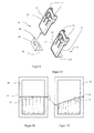
- a holding part 81 For fastening the cable tensioning device 11 by means of screws or adhesive bonding to a flat surface, a holding part 81 is provided ( FIGS. 7 and 8 ). On the holding part 81 openings 83,85 are provided, which serve to receive screws. For locking the holding part 81 with the support 13 hooks 87,89,91 are provided on the holding part 81. To receive the hooks 87, 89, 91, rectangular openings 93, 95, 97 are provided on the support 13.
- the assembly of the rope tensioning device 11 works as follows: First, the support 13 is to be fixed to a ground by means of the holding part 61 or 81. If the determination by means of screws or adhesive bonding, so the holding member 81 is to be selected. Once this is fixed to the ground, the support 13 is plugged onto the holding part 81 and locked with selbigem by the hook 87,89,91 are in operative connection with the support 13.
- the L-shaped holding part 61 is to be selected.
- the holding part 61 may be temporarily held on the frame 59 by double-sided adhesive tape or manually.
- the double-sided adhesive tape is preferably arranged on the side of the leg 63 which is oriented towards the frame 59.
- the elongated guide extensions 69 are pushed all the way into the U-shaped receptacles 71.
- the frame 59 is clamped between the leg 65 and the support 13 and the support 13 is held on the frame.
- a release of this clamping connection is prevented by the sawtooth-like surfaces 73,75, since these act as barbs to each other.
- the tab 77 has a bias which presses the surface 75 against the surface 73. Only when the tab 77 is raised against the bias, the clamp connection is released.
- the cable 37 can be tensioned by means of the cable tensioning device 11.
- the cable tensioning device 11 it is necessary to insert the cable 37 into the recesses 33 of the clamping parts 21,23 and align the clamping parts 21,23 by means of the knobs 41 and recesses to each other.
- the internal thread 25 is guided through you through-hole 53 until it comes into contact with the external thread 43.
- the second clamping part 17 is rotated until the maximum clamping action and the desired tension acts on the cable 37.
- the second end of the rope 37 is also held by a rope tensioning device 11. It would also be conceivable, however, that the second end is held only by an angle.
- a button a clamping screw o.ä. is provided.
- FIGS. 11 to 14 the cable tensioning devices 11 are each shown arranged in front of a window.
- FIG. 12 It can be seen that the cable 37 also obliquely between two rope tensioning devices 11 can be aligned.
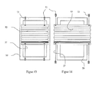
- FIGS. 13 and 14 show the possibility: a vertical arrangement of two ropes 37 in front of a window by means of four cable tensioning devices 11 for holding a plisse 93.
- the rope tensioning devices 11 are in the FIG. 13 by means of holding parts 61 and in FIG. 14 determined by holding parts 81.
- the pleat is clamped lengthwise on the ropes 37 or held for example by magnetic forces.
Abstract
Description
Die Erfindung betrifft eine Spannvorrichtung zur Spannung eines Seils gemäss Oberbegriff des Anspruchs 1, eine Befestigungsvorrichtung insbesondere zur Befestigung einer Spannvorrichtung an einem Fensterrahmen gemäss Anspruch 8 und eine Befestigungsvorrichtung insbesondere zur Befestigung einer Spannvorrichtung an einem ebenen Untergrund gemäss Anspruch 13.The invention relates to a tensioning device for tensioning a rope according to the preamble of claim 1, a fastening device in particular for fastening a tensioning device to a window frame according to claim 8 and a fastening device, in particular for fastening a tensioning device to a level base according to
Zur Befestigung von Vorhängen existieren bereits seit längerer Zeit Seilspannsysteme. Das Prinzip, das der Seilspannung zu Grunde liegt, beruht darauf, dass ein erstes Spannelement mit einem Aussengewinde mit einem zweiten Spannelement mit einem Innengewinde zusammenwirkt. Dadurch, dass das erste und das zweite Spannelement miteinander verschraubt werden wird deren Abstand zueinander verkürzt. An dem zweiten Spannelement ist ein Seil mit einem ersten Ende festgelegt. Das zweite Ende des Seils ist an einem weiteren Seilspannsystem festgelegt oder optional an einem Winkel. Die ersten Spannelemente bzw. das Spannelement und der Winkel sind an dem Untergrund durch Schraubverbindungen festgelegt. Bei Verkürzung des Abstands des ersten und zweiten Spannelements zueinander wird das Seil gespannt. Für eine zuverlässige Halterung des Seils an dem zweiten Spannelement ist dieses durch eine Durchgangsöffnung am zweiten Spannelement geführt und mittels einer Modenschraube o.ä. mit selbigem verklemmt. Dieses System ist im Vergleich zu Vorhangschienen verhältnismässig einfach zu montieren und besitzt auch ein in der Innenraumausstattung oftmals erwünschtes dezentes Erscheinungsbild.For fastening curtains rope tensioning systems have existed for some time. The principle underlying the cable tension is based on the fact that a first clamping element with an external thread cooperates with a second clamping element with an internal thread. Characterized in that the first and the second clamping element will be screwed together whose distance is shortened to each other. At the second tensioning element a rope is fixed with a first end. The second end of the rope is fixed to another rope tensioning system or optionally at an angle. The first clamping elements or the clamping element and the angle are fixed to the ground by screw. When shortening the distance of the first and second clamping element to each other, the rope is tensioned. For a reliable mounting of the rope to the second clamping element this is guided through a through hole on the second clamping element and by means of a fashion screw o. jammed with the same. This system is comparatively easy to assemble compared to curtain rails and also has a discreet appearance often desired in the interior trim.
Als nachteilig erweist sich bei diesem Seilspannsystem, dass zum Verdrehen des zweiten Spannelements relativ zum ersten Spannelement immer ein Werkzeug benötigt wird. Dies kann ein Gabelschlüssel sein, der an einer dafür vorgesehenen beidseitig abgeflachten Stelle am zweiten Spannelement zur Übertragung des Drehmoments angesetzt wird. Es existieren auch Varianten mit einer Durchgangsöffnung quer zur Längsachse des zweiten Spannelements, durch welche ein Stab, beispielsweise ein Inbusschlüssel, gesteckt wird und so ein ausreichend hohes Drehmoment: auf das zweiten Spannelement übertragen wird.A disadvantage proves in this cable clamping system that for rotating the second clamping element relative to the first clamping element always a tool is needed. This may be a fork wrench, which is attached to a designated flattened on both sides of the second clamping element for transmitting the torque. There are also variants with a passage opening transverse to the longitudinal axis of the second clamping element, through which a rod, for example an Allen wrench, is plugged and so a sufficiently high torque: is transmitted to the second clamping element.
Ein weiterer Nachteil ist dadurch gegeben, dass sich bei der Verdrehung des zweiten Spannelements das Seil zwangsläufig mitverdrillt wird und demzufolge zusätzlichen Belastungen ausgesetzt ist.Another disadvantage is given by the fact that during the rotation of the second clamping element, the rope is inevitably mitverdrillt and is therefore exposed to additional loads.
Noch ein Nachteil ist, dass das Spannsystem durch Schrauben am Untergrund festgelegt ist und die Oberfläche des Untergrunds nach Entfernen des Seilspannsystems unschöne Verletzungen aufweist.Another disadvantage is that the clamping system is fixed by screws to the substrate and the surface of the substrate after removing the rope tensioning system has unsightly injuries.
Die
In der
Aufgabe der vorliegenden Erfindung ist es daher, eine Seilsparmvorrichtung vorzuschlagen, die einfach zu spannen ist. Noch ein Ziel ist es, das Seil ohne Aufwand an der Seilspannvorrichtung festzulegen. Auch ist es Ziel, eine Seilspannvorrichtung zu zeigen, die ohne Verletzung des Untergrunds an selbigem festlegbar ist.Object of the present invention is therefore to propose a cable saving device that is easy to clamp. Another goal is to set the rope without effort on the rope tensioning device. It is also an object to show a rope tensioning device which can be fixed to the same without damaging the ground.
Erfindungsgemäss wird die Aufgabe bei einer Spannvorrichtung zur Spannung eines Seils gemäss Oberbegriff des Anspruchs 1 dadurch gelöst, dass das erste Spannteil aus zwei symmetrischen Klemmteilen besteht, welche eine gemeinsame Schnittfläche besitzen und dass an dem ersten Spannteil entlang der Längsachse eine Durchgangsöfftung vorgesehen ist, welche der Aufnahme des Seils dient und welche dadurch gebildet ist, dass an den zwei Klemmteilen jeweils entlang der Längsachse eine Vertiefung vorgesehen ist. Durch die Zweiteiligkeit des ersten Spannteils ist es nicht notwendig, das Seil in eine Durchgangöffnung am ersten Spannteil einzufädeln, sondern das Seil wird in einfacher Weise zwischen den beiden Klemmteilen eingelegt. Ein weiterer Vorteil ist, dass die Klemmteile in einfach ausgeführte einteiligen Spritzgussformen herstellbar sind, ohne dass nachträglich ein Gewinde in das erste Spannteil geschnitten werden müsste. Diese Form der Herstellung ist kostengünstig und ist mit hohen Taktzahlen durchführbar. Die Aufnahme des Seils in dem ersten Spannteil gestaltet sich durch die vorgesehene Durchgangsöffnung als sehr einfach, da dieses lediglich in die Vertiefung des ersten Klemmteils eingelegt wird und das zweite Klemmteil über das erste gelegt wird. Die Klemmwirkung des ersten Spannteils, welche auf das Seil wirkt, ist sehr gut, da diese entlang der gesamten Längsachse des ersten Spannteils wirkt.According to the invention the object is achieved in a tensioning device for tensioning a rope according to the preamble of claim 1, characterized in that the first clamping part consists of two symmetrical clamping parts, which have a common cut surface and that on the first clamping part along the longitudinal axis a Durchgangsöfftung is provided, which Receiving the rope is used and which is formed by the fact that at the two clamping parts in each case along the longitudinal axis a recess is provided. Due to the bipartite of the first clamping part, it is not necessary to thread the rope in a passage opening on the first clamping part, but the rope is inserted in a simple manner between the two clamping parts. Another advantage is that the clamping parts can be produced in simply executed one-piece injection molds, without subsequently a thread would have to be cut into the first clamping part. This form of production is inexpensive and can be carried out with high cycle rates. The inclusion of the rope in the first clamping part designed by the intended passage opening as very easy, as this is only inserted into the recess of the first clamping member and the second clamping member is placed over the first. The clamping effect of the first clamping member, which acts on the rope, is very good, since it acts along the entire longitudinal axis of the first clamping part.
In einer bevorzugten Ausführungsform ist das zweite Spannteil drehbar um die Längsachse an dem Support gehalten. Die erfmdungsgemässe Spannvorrichtung hat den Vorteil, dass durch die Halterung des zweiten Spannteils am Support der Spannvorgang des Seils einhändig erfolgen kann. Dies lässt sich darauf zurückführen, dass das Spannteil, welches von dem Support gehalten ist, während des Spannvorgangs nur mehr zu verdrehen ist und nicht mehr manuell zu halten ist, bis die Gewinde der beiden Spannteile in einer Wirkverbindung zueinander stehen. Die Spannvorrichtung ist zur Aufnahme von Seilen, vorzugsweise Drahtseilen genauso geeignet, wie zur Aufnahme von Schnüren, wie zum Beispiel Nylonschnüren.In a preferred embodiment, the second clamping member is rotatably supported about the longitudinal axis on the support. The erfmdungsgemäße clamping device has the advantage that can be done by the holder of the second clamping part on the support of the tensioning process of the rope with one hand. This can be attributed to the fact that the tensioning part, which is held by the support, is only to be twisted during the tensioning process and can no longer be held manually until the threads of the two tensioning parts are in operative connection with one another. The tensioning device is suitable for receiving ropes, preferably wire ropes, as well as for receiving cords, such as nylon cords.
In dieser bevorzugten Ausführungsform besitzt das erste Spannteil ein Aussengewinde, welches mit einem. Innengewinde des zweiten Spannteils zusammenwirkt. Außerdem ist das zweite Spannteil an dem Support gehalten. Dadurch ist gewährleistet, dass durch Verdrehen des zweiten Spannteils das erste Spannteil in selbiges hineingezogen wird, ohne dass die beiden Spannteile mühsam zueinander ausgerichtet werden müssen, um zusammenzuwirken.In this preferred embodiment, the first clamping part has an external thread, which with a. Internal thread of the second clamping part cooperates. In addition, the second clamping part is held on the support. This ensures that the first clamping part is pulled into the same by turning the second clamping part, without the two clamping parts must be laboriously aligned with each other to cooperate.
Mit Vorteil sind an den Klemmteilen entlang ihrer gemeinsamen Schnittfläche Noppen bzw. Ausnehmungen vorgesehen, welche die Klemmteile formschlüssig zueinander ausrichten. Dadurch ist das Zusammenführen und Ausrichten der beiden Klemmteile einfach und rasch durchzuführen.Advantageously, nubs or recesses are provided on the clamping parts along their common cut surface, which align the clamping parts form-fitting to one another. As a result, the merging and aligning of the two clamping parts is easy and quick to perform.
Um die Klemmkraft, welche von dem ersten Spannteil auf das Seil wirkt noch weiter zu erhöhen, sind in den Vertiefungen entlang der Längsachse mit Vorteil eine Mehrzahl von Erhöhungen vorgesehen. Um die Auszugssicherheit des Seils aus den ersten Klemmteil noch weiter zu erhöhen, ist es denkbar, dass das Seil das erste Spannteil Überragt und an dieser Stelle des Seils ein Knoten, eine Klemmschraube o. ä. angebracht sind.In order to further increase the clamping force which acts on the rope from the first tensioning part, a plurality of elevations are advantageously provided in the depressions along the longitudinal axis. In order to further increase the pull-out safety of the rope from the first clamping part, it is conceivable that the rope protrudes beyond the first clamping part and at this point of the rope a node, a clamping screw o. Ä. Are mounted.
Um eine Klemmkraft an dem ersten Spannteil erzeugen zu können, besitzt das eine Ende des ersten Spannteils mit Vorteil die Form eines Keils.In order to be able to generate a clamping force on the first clamping part, one end of the first clamping part advantageously has the shape of a wedge.
In einer bevorzugten Ausführungsform ist der Keil an mindestens einer Seite parallel zu Längsachse abgeflacht. Da diese Abflachung formschlüssig in dem Support aufgenommen ist, ist das erste Spannteil während des Spannvorgangs des Seils zuverlässig vor Verdrehung gesichert. Dies ist insofern von Bedeutung, da eine Verdrehung des Seils selbiges unnötig zusätzlich belasten und den Spannvorgang erschweren würde. Um den Verdrehschutz noch weiter zu verstärken, besitzt der Keil zweckmässigerweise mindestens eine Nut, welche parallel zur Längsachse ausgerichtet ist. Für die reine Klemmfunktion des ersten Spannteils sind die mindestens eine Abflachung und die Nut jedoch nicht erforderlich.In a preferred embodiment, the wedge is flattened on at least one side parallel to the longitudinal axis. Since this flattening is positively received in the support, the first clamping part is reliably secured against rotation during the tensioning operation of the rope. This is important insofar as a rotation of the rope unnecessarily burden the same unnecessarily and would make the tensioning process more difficult. In order to reinforce the anti-rotation even further, the wedge has expediently at least one groove which is aligned parallel to the longitudinal axis. However, for the pure clamping function of the first clamping part, the at least one flattening and the groove are not required.
Um eine Klemmkraft auf das Seil aufzubauen und den oben beschriebenen Verdrehschutz zu gewährleisten, ist an dem Support zweckmassigerweise eine Durchgangsöffnung vorgesehen, welche eine Negativform des Keils besitzt, sodass der Keil in der Durchgangsöffnung zwangsgeführt ist und bei einem relativen Verschieben des Keils in die Durchgangsöffnung entlang der Längsachse die beiden Klemmteile längs ihrer Schnittfläche aneinandergepresst sind. Je tiefer das erste Spannteil in die Durchgangsöffnung gezogen ist, umso grösser ist die erzeugte Klemmkraft. Die Durchgangsöffnung ist so gestaltet, dass der Keil nicht ganz in selbige einziehbar ist. Dieses Konstruktionsmerkmal erhöht die Klemmkraft noch weiter.In order to build a clamping force on the rope and to ensure the above-described anti-rotation, a through hole is expediently provided on the support, which has a negative mold of the wedge, so that the wedge is forcibly guided in the through hole and at a relative displacement of the wedge in the passage opening along the longitudinal axis of the two clamping members are pressed together along their cutting surface. The deeper the first clamping part is pulled into the through hole, the greater the clamping force generated. The passage opening is designed so that the wedge is not fully retractable in selbige. This design feature further increases the clamping force.
Dadurch dass die Durchgangsöffnung an der dem Keil abgewandten Seite vorteilhaft die Form eines Kreises besitzt, durch den das erste Spannteil mit seinem Aussengewinde durchgeführt ist, ist es ermöglicht, an dieser Stelle das zweite Spannteil drehbar an dem Support aufzunehmen.The fact that the passage opening on the side facing away from the wedge advantageously has the shape of a circle through which the first clamping part is performed with its external thread, it is possible to receive the second clamping part rotatably on the support at this point.
In einer besonders bevorzugten Ausführungsform ist die Drehung des zweiten Spannteils relativ zu dem Support manuell durchführbar. Der Spannvorgang ist daher ohne Zuhilfenahme von zusätzlichen Werkzeugen ermöglicht.In a particularly preferred embodiment, the rotation of the second clamping member relative to the support is manually carried out. The clamping operation is therefore possible without the aid of additional tools.
Zweckcmässigerweise besitzt das zweite Spannteil die Form eines Kreiszylinders, dessen Drehachse die gemeinsame Längsachse des ersten und zweiten Spannteils ist. Die Form des Drehzylinders ermöglicht ein einfaches Verdrehen des zweiten Spannteils zur Durchführung des Spannvorgangs.Suitably, the second clamping part has the shape of a circular cylinder whose axis of rotation is the common longitudinal axis of the first and second clamping part. The shape of the rotary cylinder allows easy rotation of the second clamping member to perform the clamping operation.
In einer besonders bevorzugten Ausführungsform besitzt das zweite Spannteil an sein nen Stirnseiten kreisförmige Absätze, durch deren Mittelpunkte die Längsachse verläuft und die der drehbaren Halterung des zweiten Spannteils an dem Support dienten. Die kreisförmigen Absätze ermöglichen, dass das zweite Spannteil auf einfache Weise drehbar gelagert an dem Support gehalten ist. Die kreisrunden Absätze sind in der Durchgangsöffnung und einer weiteren kreisförmige Öffnung am Support aufgenommen. Der Innendurchmesser dieser Öffnungen ist derart bemasst, dass die kreisrunden Absätze darin verdrehbar und spielfrei gelagert sind.In a particularly preferred embodiment, the second clamping part has on its NEN end faces circular paragraphs, through the centers of which the longitudinal axis extends and which served the rotatable mounting of the second clamping part to the support. The circular paragraphs allow the second clamping member is rotatably supported on the support in a simple manner. The circular paragraphs are added to the support in the passage opening and a further circular opening. The inner diameter of these openings is dimensioned such that the circular paragraphs are rotatable therein and stored without play.
Zeckmässigerweise sind an der Manteloberfläche des zweiten Spannteils Griffmulden vorgesehen. Dadurch gestaltet sich die manuelle Verdrehung des zweiten Spannteils besonders einfach.Zeckmässigerweise recessed grips are provided on the mantle surface of the second clamping part. As a result, the manual rotation of the second clamping part is particularly simple.
Ein weitere Aspekt der Erfindung betrifft eine Befestigungsvorrichtung, insbesondere zur Befestigung einer Spannvorrichtung an einem Fensterrahmen gemäss Oberbegriff des Anspruchs 8. Die erfindungsgemässe Befestigungsvorrichtung hat den Vorteil, dass das Halteteil eine L-Form mit einem ersten und einem zweiten Schenkel besitzt und der Support entlang des ersten Schenkels in Stufen mit dem Halteteil verrastbar ist. Die Festlegung der Spannvorrichtung an einem Rahmen gestaltet sich äusserst flexibel und komfortabel, da die Befestigungsvorrichtung durch die stufenweise Verrastung an verschieden Rahmenstärken anpassbar ist. Ferner erfolgt die Befestigung an dem Rahmen ohne diesen zu beschädigen, da die Befestigung ausschliesslich auf Klemmkräften zwischen dem Halteteil und dem Support beruht.Another aspect of the invention relates to a fastening device, in particular for fastening a clamping device to a window frame according to the preamble of claim 8. The inventive fastening device has the advantage that the holding part has an L-shape with a first and a second leg and the support along the first leg in stages with the holding part is latched. The determination of the tensioning device on a frame is extremely flexible and comfortable, since the fastening device can be adapted to different frame thicknesses by the stepwise locking. Further, the attachment to the frame without damaging it, since the attachment is based solely on clamping forces between the holding part and the support.
Um eine noch grössere Flexibilität bei der Anpassung der Befestigungsvorrichtung an die Rahmenstärke zu haben, sind der erste und der zweite Schenkel mit Vorteil zwei Einzelteile, welche miteinander zum Halte teil verrastbar sind. Diese zweiteilige Konstruktion des Halteteils hat den Vorteil, dass die Verlängerung des zweiten Spannteils, welche mit dem ersten Spannteil verrastet, verschiedene Längen haben kann. Das Halteteil kann so einfach und kostengünstig an verschieden Rahmenstärken angepasst werden, indem zweite Schenkel mit verschieden langen Verlängerungen verwendet werden.In order to have an even greater flexibility in the adaptation of the fastening device to the frame thickness, the first and the second leg are advantageously two items, which are locked together to the holding part. This two-part construction of the holding part has the advantage that the extension of the second clamping part, which locks with the first clamping part, can have different lengths. The holding part can be easily and inexpensively adapted to different frame thicknesses by second legs are used with different lengths extensions.
In einer bevorzugten Ausführungsform besitzt der Support an einer Stirnseite zwei längliche Führungsfortsätze, welche in zwei U-förmige Aufnahmen am ersten Schenkel zustellbar sind. Diese Zwangsführung erlaubt, dass der Support und das L-förimige Halteteil automatisch während der Befestigung an einem Rahmen zueinander augerichtet sind.In a preferred embodiment, the support has on one end face two elongated guide extensions, which can be delivered in two U-shaped receptacles on the first leg. This forced guidance allows the support and the L-shaped retaining part to be automatically aligned with each other during attachment to a frame.
Um die Klemmwirkung zwischen dem Support und dem L-förmigen Halteteil aufbauen zu können, ist an der Stirnseite des Supports zwischen den länglichen Führungsfortsätzen mit Vorteil eine sägezahnartige Oberfläche ausgebildet.In order to be able to build up the clamping effect between the support and the L-shaped holding part, a sawtooth-like surface is advantageously formed on the end face of the support between the elongated guide extensions.
Vorteilhaft wirkt die sägezahnartige Oberfläche mit einer Lasche am ersten Schenkel des Halteteils zusammen, indem die Lasche an ihrer dem Support zugewandten Seite ebenfalls eine sägezahnartige Oberfläche besitzt, wobei die Oberflächen derartig in Wirkverbindung stehen, dass der Support relativ zum Halteteil in einer Richtung parallel zu den länglichen Fülirungsfortsätzen verschieblich ist und in der entgegengesetzten Richtung durch die sägezahnartigen Oberflächen an dem Halteteil festlegbar ist. Durch dieses Konstruktionsmerkmal ist eine Klemmwirkung realisierbar, welches den Support mitsamt dem Halteteil sicher an dem Rahmen hält.Advantageously, the sawtooth-like surface cooperates with a tab on the first leg of the holding part by the tab also has a sawtooth-like surface on its side facing the support, wherein the surfaces are operatively connected in such a way that the support relative to the holding part in a direction parallel to the elongated Fülirungsfortsätzen is displaceable and can be fixed in the opposite direction by the sawtooth-like surfaces on the holding part. By this design feature, a clamping action can be realized, which holds the support together with the holding part securely on the frame.
Um eine sichere Wirkverbindung der beiden sägezahnartigen Oberflächen zu gewährleisten, besitzt die Lasche zweckmässigerweise eine Vorspannung, welche die sägezahnartige Oberfläche der Lasche an die sägezahnartige Oberfläche des Supports drückt.To ensure a secure operative connection of the two sawtooth-like surfaces, the tab expediently has a bias which presses the sawtooth-like surface of the tab against the sawtooth-like surface of the support.
Um die Klemmkraft zwischen dem Support und dem Halteteil zu erhöhen, ist der Winkel des L-förmigen Halteteils mit Vorteil geringfügig kleiner als 90 Grad. Bei der Festlegung der Befestigungsvorrichtung an einem Rahmen wird durch das Zusammenwirken der sägezahnartigen Oberflächen der zweite Schenkel des Halteteils an den Rahmen gepresst. Da sich der Winkel zwischen den beiden Schenkeln durch den Anpressdruck noch auf 90 Grad erweitern lässt, ist der Anpressdruck um die Rückstellkraft des L-förmigen Halteteils erhöhbar.To increase the clamping force between the support and the holding part, the angle of the L-shaped holding member is advantageously slightly smaller than 90 degrees. When fixing the fastening device to a frame, the second leg of the holding part is pressed against the frame by the interaction of the sawtooth-like surfaces. Since the angle between the two legs can be extended by the contact pressure to 90 degrees, the contact pressure can be increased by the restoring force of the L-shaped holding part.
Um eine möglichst grosse oben beschriebene Rücksfellkraft zu erzeugen, ist der zweite Schenkel des Halteteils aus Metall gefertigt.In order to produce the largest possible backfound force described above, the second leg of the holding part is made of metal.
Noch ein Aspekt der Erfindung betrifft eine Befestigungsvorrichtung insbesondere zur Befestigung einer Spannvorrichtung an einem ebenen Untergrund gemäss Oberbegriff des Anspruchs 13. Die erfindungsgemässe Befestigungsvorrichtung hat den Vorteil, dass der Support mit einem Halteteil verrastbar ist, welches an dem ebenen Untergrund, beispielsweise durch eine Schraubverbindung, festlegbar ist. Diese Befestigungsvorrichtung gewährleistet eine stabile und zugleich sehr rasch anbringbar Festlegung an einem ebenen Untergrund. Zur Verbindung an dem Untergrund sind neben Schrauben auch Verklebungen mittels Klebstoff, doppelseitigem Klebeband o.ä. denkbar.Yet another aspect of the invention relates to a fastening device, in particular for fastening a tensioning device on a flat surface according to the preamble of
Um eine stabile und trotzdem rasch herstellbare Verbindung zwischen dem Support und dem Halteteil zu schaffen, besitzt das Halteteil zweckmässigerweise mindestens zwei gegenüberliegende Haken, welche in mindestens zwei Öffnungen am Support zustellbar sind und mit dem Support verrasten.In order to provide a stable, yet rapidly producible connection between the support and the holding part, the holding part has expediently at least two opposite hooks, which are deliverable in at least two openings on the support and lock with the support.
Dadurch, dass die oben beschriebene Spannvorrichtung vorgesehen ist vorteilhaft mit beiden Halteteilen verrastbar zu sein, ist es ermöglicht, die Spannvorrichtung an nahezu jedem Untergrund festzulegen. Dabei kann das Seil vertikal, horizontal aber auch in jeder anderen Lage zwischen zwei Seilspannvorrichtungen gespannt sein. Ist es an einem Fensterrahmen mit einem der oben beschriebenen Halteteile festgelegt so hat dies den Vorteil, das das Fenster auch bei zugezogenem Vorhang zu öffnen ist. Dem Anwender ist mit dem erfindungsgemässen Seilspannset die Möglichkeit gegeben selbiges an seine Bedürfnisse anzupassen. Dabei bestehen die Anpassungsmöglichkeiten aus der Lage des Seils, der Länge des Seils durch einfaches Ablängen des selbigen und der Art der Festlegung der Seilspannvorrichtungen durch die Auswahl eines Paares eines der beiden Halteteile.Characterized in that the clamping device described above is provided to be advantageous latched with two holding parts, it is possible to set the clamping device on almost any surface. The rope can be stretched vertically, horizontally but also in any other position between two rope tensioning devices. If it is fixed to a window frame with one of the holding parts described above, this has the advantage that the window is open even when the curtain is closed. The user is given the opportunity with the inventive cable tensioning set to adapt it to his needs. The adjustment possibilities consist of the position of the rope, the length of the rope by simply cutting the same and the manner of fixing the rope tensioning devices by selecting a pair of one of the two holding parts.
In einer besonders bevorzugten Ausführungsform, ist das zweite Spannteil drehbar um die Längsachse an dem Support gehalten ist. Die erfindungsgemässe Spannvomchtung wird dadurch einhändig und werkzeugfrei bedienbar.In a particularly preferred embodiment, the second clamping part is rotatably held about the longitudinal axis on the support. The tensioning device according to the invention is thereby operated with one hand and without tools.
Nachfolgend wird die Erfindung unter Bezugnahme auf die Figuren in schematischer Darstellung näher im Detail beschrieben. Es zeigt:
- Figur 1:
- eine perspektivische Ansicht der erfindungsgemassen Seilspann- vorrichtung,
- Figur 2:
- einen Support in einer ersten perspektivischen Ansicht;
- Figur 3:
- den Support aus
Figur 2 in einer zweiten, perspektivischen Ansicht; - Figur4:
- ein erstes Spannteil in einer perspektivischen Ansicht;
- Figur 5:
- perspektivische Ansicht eines Klemmteils;
- Figur 6:
- perspektivische Ansicht eines zweiten Spannteils;
- Figur 7:
- ein Halteteil in einer ersten perspektivischen Ansicht;
- Figur 8:
- das Halteteil aus
Figur 7 in einer zweiten perspektivischen Ansicht; - Figur 9:
- ein L-förmiges Halteteil vor dem zusammengesetzten Zustand;
- Figur 10:
- das L-förmige Halteteil im zusanmengesetzten Zustand;
- Figur 11:
- die erfindungsgemasse Seilspannvorrichtung angeordnet an einem. Fensterrahmen in horizontaler Lage;
- Figur 12:
- die Seilspannvorrichtung angeordnet an einem Fensterrahmen in schräger Lage;
- Figur 13:
- die Seilspannvornchtung angeordnet an einem Fensterrahmen in vertikaler Lage und
Figur 24;- die Seilspannvorrichtung angeordnet vor einem Fenster in vertikal ler Lage, wobei die Seilspannvorrichtung am Fensteruntergrund festgelegt ist.
- FIG. 1:
- a perspective view of the inventive cable tensioning device,
- FIG. 2:
- a support in a first perspective view;
- FIG. 3:
- the support
FIG. 2 in a second, perspective view; - Figur4:
- a first clamping part in a perspective view;
- FIG. 5:
- perspective view of a clamping part;
- FIG. 6:
- perspective view of a second clamping part;
- FIG. 7:
- a holding part in a first perspective view;
- FIG. 8:
- the holding part off
FIG. 7 in a second perspective view; - FIG. 9:
- an L-shaped holding part before the assembled state;
- FIG. 10:
- the L-shaped holding part in zusanmengesetzten state;
- FIG. 11:
- the inventive rope tensioning device arranged on a. Window frame in horizontal position;
- FIG. 12:
- the rope tensioning device arranged on a window frame in an oblique position;
- FIG. 13:
- the Seilspannvornchtung arranged on a window frame in a vertical position and
- Figure 24;
- the rope tensioning device arranged in front of a window in a vertical position, wherein the rope tensioning device is fixed to the window base.
In
In den
An jedem der beiden Klemmteile 27,29 ist entlang der Längsachse 19 eine Vertiefung 33 vorgesehen. Im zusammengesetzten Zustand bilden die Vertiefungen 33 eine Durchgangsöffnung 34, welcher der Aufnahme eines Seils 37 dient (
Das zweite Spannteil 17 hat die Form eines Drehzylinders und besitzt ein Innengewinde 43, dessen Mittelpunktsachse die Längsachse 19 ist und mit dem Aussengewinde 25 zusammenwirkt (
Der Keil 27 ist in einer Durchgangsöffnung 53 des Supports 13 aufgenommen (
Die
Zur Befestigung der Seilspannvorrichtung 11 mittels Schrauben oder Verklebung an einem ebenen Untergrund ist ein Halteteil 81 vorgesehen (
Die Montage der Seilspannvorrichtung 11 funktioniert wie folgt: Zuerst ist der Support 13 an einem Untergrund mittels des Halteteils 61 oder 81 festzulegen. Soll die Festlegung mittels Schrauben oder Verklebung erfolgen, so ist das Halteteils 81 zu wählen. sobald dieses am Untergrund festgelegt ist, wird der Support 13 auf das Halteteils 81 aufgesteckt und verrastet mit selbigem, indem die Haken 87,89,91 mit dem Support 13 in Wirkverbindung stehen.The assembly of the
Soll der Support an einem Rahmen 59 festgelegt werden, so ist das L-förmige Halteteil 61 zu wählen. Das Halteteil 61 kann mittels doppelseitigem Klebeband oder manuell provisorisch an dem Rahmen 59 gehalten sein. Das doppelseitige Klebeband ist dabei vorzugsweise an der Seite des Schenkels 63 angeordnet, welche zu dem Rahmen 59 hin orientiert ist. Die länglichen Führungsfortsätze 69 werden bis zum Anschlag in die U-förmigen Aufnahmen 71 geschoben. Dadurch ist der Rahmen 59 zwischen dem Schenkel 65 und dem Support 13 eingeklemmt und der Support 13 an dem Rahmen gehalten. Ein Lösen diese Klemmverbindung ist durch die sägezahnähnlichen Oberflächen 73,75 verhindert, da diese zueinander als Widerhaken wirken. Die Lasche 77 besitzt eine Vorspannung, welche die Oberfläche 75 an die Oberfläche 73 drückt. Erst wenn die Lasche 77 entgegen der Vorspannung angehoben wird, wird die Klemmverbindung gelöst.If the support is to be fixed to a
Ist der Support 13 mitsamt dem zweiten Spannteil 17 an dem Untergrund festgelegt, kann das Seil 37 mittels der Seilspannvorrichtung 11 gespannt werden. Dazu ist es notwendig das Seil 37 in die Vertiefungen 33 der Klemmteile 21,23 einzulegen und die Klemmteile 21,23 mittels der Noppen 41 und Ausnehmungen zueinander auszurichten. Das Innengewinde 25 wird durch dir Durchgangsöffnung 53 geführt, bis es mit dem Aussengewinde 43 in Kontakt tritt. Das zweite Spannteil 17 wird solange gedreht, bis die maximale Klemmwirkung und die gewünschte Spannung auf das Seil 37 wirkt. Das zweite Ende des Seils 37 ist ebenfalls von einer Seilspannvorrichtung 11 gehalten. Denkbar wäre es jedoch auch, dass das zweite Ende lediglich durch einen Winkel gehalten ist. Zur zusätzlichen Vermeidung eines Ausziehens des Seils 37 aus dem ersten Spannteil 15 ist es denkbar, dass an dem Seilende ein Knopf, eine Klemmschraube o.ä. vorgesehen, ist.If the
In den
- 1111
- SeilspannvorrichtungRope tensioner
- 1313
- SupportSupport
- 1515
- Erstes SpannteilFirst clamping part
- 1717
- Zweites SpannteilSecond clamping part
- 1919
- Längsachselongitudinal axis
- 21,2321.23
- Klemmteileclamping parts
- 2424
- Schnittflächesection
- 2525
- Aussengewindeexternal thread
- 2727
- Keilwedge
- 2929
- Ebene FlächenPlane surfaces
- 3131
- Nutengroove
- 3333
- Vertiefungenwells
- 3434
- Durchgangsöffnung am ersten SpannteilThrough opening on the first clamping part
- 3535
- Punktförmige ErhebungenPoint-shaped elevations
- 3737
- Seilrope
- 3939
- Klemmverstärkungclamping gain
- 4141
- Noppenburl
- 4343
- Innengewindeinner thread
- 45,4745.47
- Stirnseitenfront sides
- 4949
- Kreisförmige AbsätzeCircular paragraphs
- 5151
- Griffmuldenhandholds
- 5353
- Durchgangsöffnung am SupportThrough opening on the support
- 55,5755.57
- Kreisförmige ÖffnungenCircular openings
- 5959
- Fensterrahmenwindow frame
- 6161
- L-förmiges HalteteilL-shaped holding part
- 63,6563.65
- Schenkelleg
- 6666
- Widerhakenbarb
- 6767
- Stirnseitefront
- 6868
- Verlängerungrenewal
- 6969
- Längliche FührungsfortsätzeElongated guide extensions
- 7171
- U-förmige AufnahmenU-shaped shots
- 73,7573,75
- Sägezahnartige OberflächenSawtooth surfaces
- 7777
- Lascheflap
- 8181
- Halteteilholding part
- 83,8583.85
- Öffnungenopenings
- 87,89,9187,89,91
- Hakenhook
- 93,95,9793,95,97
- Rechteckige ÖffnungenRectangular openings
Claims (15)
dass das erste Spannteil (15) aus zwei symmetrischen Klemmteilen (21,23) besteht, welche eine gemeinsame Schnittfläche (24) besitzen und
dass an dem ersten Spannteil (15) entlang der Längsachse (19) eine Durchgangsöffnung (34) vorgesehen ist, welche der Aufnahme des Seils (37) dient und welche dadurch gebildet ist, dass an den zwei Klemmteilen (21,23) jeweils entlang der Längsachse (19) eine Vertiefung (33) vorgesehen ist.Clamping device (11) for tensioning a cable (37), which in particular serves to hold a curtain, with
in that the first clamping part (15) consists of two symmetrical clamping parts (21, 23) which have a common cut surface (24) and
that a passage opening (34) is provided on the first clamping part (15) along the longitudinal axis (19) which the recording of the rope (37) is used and which is formed by the two clamping parts (21,23) respectively along the Longitudinal axis (19) has a recess (33) is provided.
dass das Halteteil (61) eine L-Form mit einem ersten und einem zweiten Schenkel (63,65) besitzt und der Support (13) entlang des ersten Schenkels (63) in Stufen mit dem Halteteil (61) verrastbar ist.Fixing device, in particular for fastening a tensioning device (11), in particular a Seilspannvorrichtuug for curtains, on a window frame (59)
in that the holding part (61) has an L-shape with a first and a second leg (63, 65) and the support (13) can be latched in steps with the holding part (61) along the first leg (63).
dass der Support (13) mit dem Halteteil (81) verrastbar ist, welches an dem ebenen Untergrund, beispielsweise durch eine Schraubverbindung, festlegbar ist.Fastening device in particular for fastening a tensioning device (11), in particular a cable tensioning device for curtains, on a level surface with
in that the support (13) can be latched to the holding part (81), which can be fixed to the flat base, for example by a screw connection.
Applications Claiming Priority (1)
| Application Number | Priority Date | Filing Date | Title |
|---|---|---|---|
| CH01585/09A CH701983A1 (en) | 2009-10-14 | 2009-10-14 | Tensioner for curtain rope. |
Publications (3)
| Publication Number | Publication Date |
|---|---|
| EP2329747A2 true EP2329747A2 (en) | 2011-06-08 |
| EP2329747A3 EP2329747A3 (en) | 2011-06-29 |
| EP2329747B1 EP2329747B1 (en) | 2013-09-25 |
Family
ID=42712467
Family Applications (1)
| Application Number | Title | Priority Date | Filing Date |
|---|---|---|---|
| EP20100187398 Not-in-force EP2329747B1 (en) | 2009-10-14 | 2010-10-13 | Tension device for curtain rope |
Country Status (3)
| Country | Link |
|---|---|
| EP (1) | EP2329747B1 (en) |
| CH (1) | CH701983A1 (en) |
| DE (1) | DE202010017706U1 (en) |
Cited By (6)
| Publication number | Priority date | Publication date | Assignee | Title |
|---|---|---|---|---|
| DE202011052021U1 (en) | 2011-11-18 | 2012-11-19 | Inventex Establishment | Clamping bracket for fastening an object, in particular a cable tensioning device for a sun and / or privacy protection device, on a window or door frame |
| DE202012103023U1 (en) | 2012-08-10 | 2013-02-07 | Inventex Establishment | Clamping device for tensioning at least one cable of a bracket and / or guiding a pleated blind and / or a blind and / or a curtain and / or guide for a pleated blind and / or a blind and / or a curtain |
| EP2594165A1 (en) | 2011-11-18 | 2013-05-22 | Inventex Establishment | Clamp holder for fixing an object, in particular a cable tensioning device for a sun screen or blind, to a window or door frame |
| DE202013103389U1 (en) | 2012-11-20 | 2013-08-30 | Rolladen-Schönberger GmbH & Co. KG Rolladenfabrik | Tool holders |
| DE202013100640U1 (en) | 2012-08-02 | 2013-11-04 | Rolladen-Schönberger GmbH & Co. KG Rolladenfabrik | Cable tensioning device and tensioning set for a tensioning cable for supporting a curtain element |
| EP3189754A1 (en) * | 2016-01-08 | 2017-07-12 | Inventex Establishment | Fixing device for fixing a sun or view protection device on a window or door frame |
Citations (2)
| Publication number | Priority date | Publication date | Assignee | Title |
|---|---|---|---|---|
| DE29722144U1 (en) | 1997-12-16 | 1998-02-12 | Piing Heh Enterprise Co | Suspension cable device for curtains |
| DE20107752U1 (en) | 2001-05-08 | 2001-08-09 | Evo Hardware Co | Curtain clip |
Family Cites Families (2)
| Publication number | Priority date | Publication date | Assignee | Title |
|---|---|---|---|---|
| DE20106163U1 (en) * | 2001-04-07 | 2001-07-26 | Bannier Reinhard | Hanging device for folding or pleated blinds |
| DE202005013937U1 (en) * | 2005-09-03 | 2005-12-22 | Vision-In Gmbh | Holding device for e.g. curtains, has two supporters by which draperies or curtains are supported and clamping device for fastening curtains, where device is made up of wood, plastic, metal and transparent plastics |
-
2009
- 2009-10-14 CH CH01585/09A patent/CH701983A1/en not_active Application Discontinuation
-
2010
- 2010-10-13 EP EP20100187398 patent/EP2329747B1/en not_active Not-in-force
- 2010-10-13 DE DE202010017706U patent/DE202010017706U1/en not_active Expired - Lifetime
Patent Citations (2)
| Publication number | Priority date | Publication date | Assignee | Title |
|---|---|---|---|---|
| DE29722144U1 (en) | 1997-12-16 | 1998-02-12 | Piing Heh Enterprise Co | Suspension cable device for curtains |
| DE20107752U1 (en) | 2001-05-08 | 2001-08-09 | Evo Hardware Co | Curtain clip |
Cited By (7)
| Publication number | Priority date | Publication date | Assignee | Title |
|---|---|---|---|---|
| DE202011052021U1 (en) | 2011-11-18 | 2012-11-19 | Inventex Establishment | Clamping bracket for fastening an object, in particular a cable tensioning device for a sun and / or privacy protection device, on a window or door frame |
| EP2594165A1 (en) | 2011-11-18 | 2013-05-22 | Inventex Establishment | Clamp holder for fixing an object, in particular a cable tensioning device for a sun screen or blind, to a window or door frame |
| DE202013100640U1 (en) | 2012-08-02 | 2013-11-04 | Rolladen-Schönberger GmbH & Co. KG Rolladenfabrik | Cable tensioning device and tensioning set for a tensioning cable for supporting a curtain element |
| DE102012111170A1 (en) * | 2012-08-02 | 2014-02-06 | Rolladen-Schönberger GmbH & Co. KG Rolladenfabrik | Tool holders |
| DE202012103023U1 (en) | 2012-08-10 | 2013-02-07 | Inventex Establishment | Clamping device for tensioning at least one cable of a bracket and / or guiding a pleated blind and / or a blind and / or a curtain and / or guide for a pleated blind and / or a blind and / or a curtain |
| DE202013103389U1 (en) | 2012-11-20 | 2013-08-30 | Rolladen-Schönberger GmbH & Co. KG Rolladenfabrik | Tool holders |
| EP3189754A1 (en) * | 2016-01-08 | 2017-07-12 | Inventex Establishment | Fixing device for fixing a sun or view protection device on a window or door frame |
Also Published As
| Publication number | Publication date |
|---|---|
| CH701983A1 (en) | 2011-04-15 |
| EP2329747A3 (en) | 2011-06-29 |
| EP2329747B1 (en) | 2013-09-25 |
| DE202010017706U1 (en) | 2012-05-10 |
Similar Documents
| Publication | Publication Date | Title |
|---|---|---|
| DE10158005B4 (en) | Ironing ferrule | |
| DE102008060126B4 (en) | clamping system | |
| EP2329747B1 (en) | Tension device for curtain rope | |
| AT512283B1 (en) | SOLAR MOUNTING SYSTEM | |
| DE3020838C2 (en) | ||
| DE1801913A1 (en) | Arrangement of fittings in profile frames of windows, doors or the like. | |
| DE3336168C2 (en) | ||
| DE4244603A1 (en) | Clamping connector for profiled rods | |
| DE19507715C1 (en) | Device for fastening component to rail-shaped support | |
| DE10208362B4 (en) | Device for adjusting a structure and an adjustment method | |
| WO2019175184A1 (en) | Device and method for securing frames | |
| DE60210236T2 (en) | ROPE TERMINAL AND LUGGAGE BRACKET | |
| EP0602456A1 (en) | Pipe clamp | |
| DE4108455A1 (en) | Cramp for cramping up door linings to wall openings - is one piece cramp with three adjusting jaws simultaneously adjusting alignment and fixing anchors | |
| DE202009005997U1 (en) | rosette arrangement | |
| DE102008050901B4 (en) | Sensor holding device and sensor-sensor holder combination | |
| DE102014205400B4 (en) | furniture | |
| DE202018105098U1 (en) | Attachment system for securing an item to a carrier | |
| DE102020126347B3 (en) | Spacer, guide rail for a venetian blind or venetian blind and venetian blind and blind and method therefor | |
| DE102018101285A1 (en) | Corner connector | |
| DE102016206722A1 (en) | Clamping bracket for a tensioning cord of a shading system and shading system | |
| DE202013102566U1 (en) | Fastener with thread detachable nut thread | |
| EP3712371A1 (en) | Shading device | |
| EP3034382A1 (en) | Device for holding a support on a supporting assembly | |
| DE202014102420U1 (en) | mounting system |
Legal Events
| Date | Code | Title | Description |
|---|---|---|---|
| PUAI | Public reference made under article 153(3) epc to a published international application that has entered the european phase |
Free format text: ORIGINAL CODE: 0009012 |
|
| PUAL | Search report despatched |
Free format text: ORIGINAL CODE: 0009013 |
|
| AK | Designated contracting states |
Kind code of ref document: A2 Designated state(s): AL AT BE BG CH CY CZ DE DK EE ES FI FR GB GR HR HU IE IS IT LI LT LU LV MC MK MT NL NO PL PT RO RS SE SI SK SM TR |
|
| AX | Request for extension of the european patent |
Extension state: BA ME |
|
| AK | Designated contracting states |
Kind code of ref document: A3 Designated state(s): AL AT BE BG CH CY CZ DE DK EE ES FI FR GB GR HR HU IE IS IT LI LT LU LV MC MK MT NL NO PL PT RO RS SE SI SK SM TR |
|
| AX | Request for extension of the european patent |
Extension state: BA ME |
|
| 17P | Request for examination filed |
Effective date: 20111229 |
|
| GRAP | Despatch of communication of intention to grant a patent |
Free format text: ORIGINAL CODE: EPIDOSNIGR1 |
|
| RIC1 | Information provided on ipc code assigned before grant |
Ipc: A47H 1/19 20060101AFI20130422BHEP Ipc: E06B 9/327 20060101ALI20130422BHEP |
|
| INTG | Intention to grant announced |
Effective date: 20130527 |
|
| GRAS | Grant fee paid |
Free format text: ORIGINAL CODE: EPIDOSNIGR3 |
|
| GRAA | (expected) grant |
Free format text: ORIGINAL CODE: 0009210 |
|
| AK | Designated contracting states |
Kind code of ref document: B1 Designated state(s): AL AT BE BG CH CY CZ DE DK EE ES FI FR GB GR HR HU IE IS IT LI LT LU LV MC MK MT NL NO PL PT RO RS SE SI SK SM TR |
|
| REG | Reference to a national code |
Ref country code: GB Ref legal event code: FG4D Free format text: NOT ENGLISH |
|
| REG | Reference to a national code |
Ref country code: CH Ref legal event code: EP |
|
| REG | Reference to a national code |
Ref country code: AT Ref legal event code: REF Ref document number: 633387 Country of ref document: AT Kind code of ref document: T Effective date: 20131015 |
|
| REG | Reference to a national code |
Ref country code: IE Ref legal event code: FG4D Free format text: LANGUAGE OF EP DOCUMENT: GERMAN |
|
| REG | Reference to a national code |
Ref country code: DE Ref legal event code: R096 Ref document number: 502010004847 Country of ref document: DE Effective date: 20131121 |
|
| REG | Reference to a national code |
Ref country code: CH Ref legal event code: NV Representative=s name: FIAMMENGHI-FIAMMENGHI, CH |
|
| PG25 | Lapsed in a contracting state [announced via postgrant information from national office to epo] |
Ref country code: LT Free format text: LAPSE BECAUSE OF FAILURE TO SUBMIT A TRANSLATION OF THE DESCRIPTION OR TO PAY THE FEE WITHIN THE PRESCRIBED TIME-LIMIT Effective date: 20130925 Ref country code: SE Free format text: LAPSE BECAUSE OF FAILURE TO SUBMIT A TRANSLATION OF THE DESCRIPTION OR TO PAY THE FEE WITHIN THE PRESCRIBED TIME-LIMIT Effective date: 20130925 Ref country code: HR Free format text: LAPSE BECAUSE OF FAILURE TO SUBMIT A TRANSLATION OF THE DESCRIPTION OR TO PAY THE FEE WITHIN THE PRESCRIBED TIME-LIMIT Effective date: 20130925 Ref country code: NO Free format text: LAPSE BECAUSE OF FAILURE TO SUBMIT A TRANSLATION OF THE DESCRIPTION OR TO PAY THE FEE WITHIN THE PRESCRIBED TIME-LIMIT Effective date: 20131225 |
|
| REG | Reference to a national code |
Ref country code: NL Ref legal event code: VDEP Effective date: 20130925 |
|
| REG | Reference to a national code |
Ref country code: LT Ref legal event code: MG4D |
|
| PG25 | Lapsed in a contracting state [announced via postgrant information from national office to epo] |
Ref country code: SI Free format text: LAPSE BECAUSE OF FAILURE TO SUBMIT A TRANSLATION OF THE DESCRIPTION OR TO PAY THE FEE WITHIN THE PRESCRIBED TIME-LIMIT Effective date: 20130925 Ref country code: FI Free format text: LAPSE BECAUSE OF FAILURE TO SUBMIT A TRANSLATION OF THE DESCRIPTION OR TO PAY THE FEE WITHIN THE PRESCRIBED TIME-LIMIT Effective date: 20130925 Ref country code: GR Free format text: LAPSE BECAUSE OF FAILURE TO SUBMIT A TRANSLATION OF THE DESCRIPTION OR TO PAY THE FEE WITHIN THE PRESCRIBED TIME-LIMIT Effective date: 20131226 Ref country code: RS Free format text: LAPSE BECAUSE OF FAILURE TO SUBMIT A TRANSLATION OF THE DESCRIPTION OR TO PAY THE FEE WITHIN THE PRESCRIBED TIME-LIMIT Effective date: 20130925 Ref country code: LV Free format text: LAPSE BECAUSE OF FAILURE TO SUBMIT A TRANSLATION OF THE DESCRIPTION OR TO PAY THE FEE WITHIN THE PRESCRIBED TIME-LIMIT Effective date: 20130925 |
|
| BERE | Be: lapsed |
Owner name: INVENTEX ESTABLISHMENT Effective date: 20131031 |
|
| PG25 | Lapsed in a contracting state [announced via postgrant information from national office to epo] |
Ref country code: SK Free format text: LAPSE BECAUSE OF FAILURE TO SUBMIT A TRANSLATION OF THE DESCRIPTION OR TO PAY THE FEE WITHIN THE PRESCRIBED TIME-LIMIT Effective date: 20130925 Ref country code: EE Free format text: LAPSE BECAUSE OF FAILURE TO SUBMIT A TRANSLATION OF THE DESCRIPTION OR TO PAY THE FEE WITHIN THE PRESCRIBED TIME-LIMIT Effective date: 20130925 Ref country code: IS Free format text: LAPSE BECAUSE OF FAILURE TO SUBMIT A TRANSLATION OF THE DESCRIPTION OR TO PAY THE FEE WITHIN THE PRESCRIBED TIME-LIMIT Effective date: 20140125 Ref country code: NL Free format text: LAPSE BECAUSE OF FAILURE TO SUBMIT A TRANSLATION OF THE DESCRIPTION OR TO PAY THE FEE WITHIN THE PRESCRIBED TIME-LIMIT Effective date: 20130925 Ref country code: RO Free format text: LAPSE BECAUSE OF FAILURE TO SUBMIT A TRANSLATION OF THE DESCRIPTION OR TO PAY THE FEE WITHIN THE PRESCRIBED TIME-LIMIT Effective date: 20130925 Ref country code: CZ Free format text: LAPSE BECAUSE OF FAILURE TO SUBMIT A TRANSLATION OF THE DESCRIPTION OR TO PAY THE FEE WITHIN THE PRESCRIBED TIME-LIMIT Effective date: 20130925 |
|
| PG25 | Lapsed in a contracting state [announced via postgrant information from national office to epo] |
Ref country code: CY Free format text: LAPSE BECAUSE OF FAILURE TO SUBMIT A TRANSLATION OF THE DESCRIPTION OR TO PAY THE FEE WITHIN THE PRESCRIBED TIME-LIMIT Effective date: 20130925 Ref country code: ES Free format text: LAPSE BECAUSE OF FAILURE TO SUBMIT A TRANSLATION OF THE DESCRIPTION OR TO PAY THE FEE WITHIN THE PRESCRIBED TIME-LIMIT Effective date: 20130925 Ref country code: PL Free format text: LAPSE BECAUSE OF FAILURE TO SUBMIT A TRANSLATION OF THE DESCRIPTION OR TO PAY THE FEE WITHIN THE PRESCRIBED TIME-LIMIT Effective date: 20130925 |
|
| REG | Reference to a national code |
Ref country code: DE Ref legal event code: R097 Ref document number: 502010004847 Country of ref document: DE |
|
| PG25 | Lapsed in a contracting state [announced via postgrant information from national office to epo] |
Ref country code: MC Free format text: LAPSE BECAUSE OF FAILURE TO SUBMIT A TRANSLATION OF THE DESCRIPTION OR TO PAY THE FEE WITHIN THE PRESCRIBED TIME-LIMIT Effective date: 20130925 Ref country code: PT Free format text: LAPSE BECAUSE OF FAILURE TO SUBMIT A TRANSLATION OF THE DESCRIPTION OR TO PAY THE FEE WITHIN THE PRESCRIBED TIME-LIMIT Effective date: 20140127 |
|
| REG | Reference to a national code |
Ref country code: IE Ref legal event code: MM4A |
|
| PLBE | No opposition filed within time limit |
Free format text: ORIGINAL CODE: 0009261 |
|
| STAA | Information on the status of an ep patent application or granted ep patent |
Free format text: STATUS: NO OPPOSITION FILED WITHIN TIME LIMIT |
|
| PG25 | Lapsed in a contracting state [announced via postgrant information from national office to epo] |
Ref country code: IT Free format text: LAPSE BECAUSE OF FAILURE TO SUBMIT A TRANSLATION OF THE DESCRIPTION OR TO PAY THE FEE WITHIN THE PRESCRIBED TIME-LIMIT Effective date: 20130925 |
|
| 26N | No opposition filed |
Effective date: 20140626 |
|
| PG25 | Lapsed in a contracting state [announced via postgrant information from national office to epo] |
Ref country code: DK Free format text: LAPSE BECAUSE OF FAILURE TO SUBMIT A TRANSLATION OF THE DESCRIPTION OR TO PAY THE FEE WITHIN THE PRESCRIBED TIME-LIMIT Effective date: 20130925 Ref country code: BE Free format text: LAPSE BECAUSE OF NON-PAYMENT OF DUE FEES Effective date: 20131031 |
|
| REG | Reference to a national code |
Ref country code: DE Ref legal event code: R097 Ref document number: 502010004847 Country of ref document: DE Effective date: 20140626 |
|
| PG25 | Lapsed in a contracting state [announced via postgrant information from national office to epo] |
Ref country code: IE Free format text: LAPSE BECAUSE OF NON-PAYMENT OF DUE FEES Effective date: 20131013 |
|
| PG25 | Lapsed in a contracting state [announced via postgrant information from national office to epo] |
Ref country code: SM Free format text: LAPSE BECAUSE OF FAILURE TO SUBMIT A TRANSLATION OF THE DESCRIPTION OR TO PAY THE FEE WITHIN THE PRESCRIBED TIME-LIMIT Effective date: 20130925 |
|
| REG | Reference to a national code |
Ref country code: CH Ref legal event code: PL |
|
| GBPC | Gb: european patent ceased through non-payment of renewal fee |
Effective date: 20141013 |
|
| PG25 | Lapsed in a contracting state [announced via postgrant information from national office to epo] |
Ref country code: TR Free format text: LAPSE BECAUSE OF FAILURE TO SUBMIT A TRANSLATION OF THE DESCRIPTION OR TO PAY THE FEE WITHIN THE PRESCRIBED TIME-LIMIT Effective date: 20130925 |
|
| PG25 | Lapsed in a contracting state [announced via postgrant information from national office to epo] |
Ref country code: LU Free format text: LAPSE BECAUSE OF NON-PAYMENT OF DUE FEES Effective date: 20131013 Ref country code: HU Free format text: LAPSE BECAUSE OF FAILURE TO SUBMIT A TRANSLATION OF THE DESCRIPTION OR TO PAY THE FEE WITHIN THE PRESCRIBED TIME-LIMIT; INVALID AB INITIO Effective date: 20101013 Ref country code: MK Free format text: LAPSE BECAUSE OF FAILURE TO SUBMIT A TRANSLATION OF THE DESCRIPTION OR TO PAY THE FEE WITHIN THE PRESCRIBED TIME-LIMIT Effective date: 20130925 Ref country code: CH Free format text: LAPSE BECAUSE OF NON-PAYMENT OF DUE FEES Effective date: 20141031 Ref country code: LI Free format text: LAPSE BECAUSE OF NON-PAYMENT OF DUE FEES Effective date: 20141031 Ref country code: GB Free format text: LAPSE BECAUSE OF NON-PAYMENT OF DUE FEES Effective date: 20141013 Ref country code: BG Free format text: LAPSE BECAUSE OF FAILURE TO SUBMIT A TRANSLATION OF THE DESCRIPTION OR TO PAY THE FEE WITHIN THE PRESCRIBED TIME-LIMIT Effective date: 20130925 |
|
| PG25 | Lapsed in a contracting state [announced via postgrant information from national office to epo] |
Ref country code: MT Free format text: LAPSE BECAUSE OF FAILURE TO SUBMIT A TRANSLATION OF THE DESCRIPTION OR TO PAY THE FEE WITHIN THE PRESCRIBED TIME-LIMIT Effective date: 20130925 |
|
| REG | Reference to a national code |
Ref country code: FR Ref legal event code: PLFP Year of fee payment: 6 |
|
| REG | Reference to a national code |
Ref country code: FR Ref legal event code: PLFP Year of fee payment: 7 |
|
| PGFP | Annual fee paid to national office [announced via postgrant information from national office to epo] |
Ref country code: FR Payment date: 20161031 Year of fee payment: 7 |
|
| PGFP | Annual fee paid to national office [announced via postgrant information from national office to epo] |
Ref country code: AT Payment date: 20161031 Year of fee payment: 7 |
|
| REG | Reference to a national code |
Ref country code: AT Ref legal event code: MM01 Ref document number: 633387 Country of ref document: AT Kind code of ref document: T Effective date: 20171013 |
|
| REG | Reference to a national code |
Ref country code: FR Ref legal event code: ST Effective date: 20180629 |
|
| PG25 | Lapsed in a contracting state [announced via postgrant information from national office to epo] |
Ref country code: FR Free format text: LAPSE BECAUSE OF NON-PAYMENT OF DUE FEES Effective date: 20171031 Ref country code: AT Free format text: LAPSE BECAUSE OF NON-PAYMENT OF DUE FEES Effective date: 20171013 |
|
| PG25 | Lapsed in a contracting state [announced via postgrant information from national office to epo] |
Ref country code: AL Free format text: LAPSE BECAUSE OF FAILURE TO SUBMIT A TRANSLATION OF THE DESCRIPTION OR TO PAY THE FEE WITHIN THE PRESCRIBED TIME-LIMIT Effective date: 20130925 |
|
| PGFP | Annual fee paid to national office [announced via postgrant information from national office to epo] |
Ref country code: DE Payment date: 20191024 Year of fee payment: 10 |
|
| REG | Reference to a national code |
Ref country code: DE Ref legal event code: R119 Ref document number: 502010004847 Country of ref document: DE |
|
| PG25 | Lapsed in a contracting state [announced via postgrant information from national office to epo] |
Ref country code: DE Free format text: LAPSE BECAUSE OF NON-PAYMENT OF DUE FEES Effective date: 20210501 |