EP2328640B1 - Medical injector with post-autoreconstitution dose setting and autoplunger drive - Google Patents
Medical injector with post-autoreconstitution dose setting and autoplunger drive Download PDFInfo
- Publication number
- EP2328640B1 EP2328640B1 EP09815269.7A EP09815269A EP2328640B1 EP 2328640 B1 EP2328640 B1 EP 2328640B1 EP 09815269 A EP09815269 A EP 09815269A EP 2328640 B1 EP2328640 B1 EP 2328640B1
- Authority
- EP
- European Patent Office
- Prior art keywords
- plunger
- state
- stopper
- stop block
- spring
- Prior art date
- Legal status (The legal status is an assumption and is not a legal conclusion. Google has not performed a legal analysis and makes no representation as to the accuracy of the status listed.)
- Active
Links
Images


Classifications
-
- A—HUMAN NECESSITIES
- A61—MEDICAL OR VETERINARY SCIENCE; HYGIENE
- A61M—DEVICES FOR INTRODUCING MEDIA INTO, OR ONTO, THE BODY; DEVICES FOR TRANSDUCING BODY MEDIA OR FOR TAKING MEDIA FROM THE BODY; DEVICES FOR PRODUCING OR ENDING SLEEP OR STUPOR
- A61M5/00—Devices for bringing media into the body in a subcutaneous, intra-vascular or intramuscular way; Accessories therefor, e.g. filling or cleaning devices, arm-rests
- A61M5/178—Syringes
- A61M5/19—Syringes having more than one chamber, e.g. including a manifold coupling two parallelly aligned syringes through separate channels to a common discharge assembly
-
- A—HUMAN NECESSITIES
- A61—MEDICAL OR VETERINARY SCIENCE; HYGIENE
- A61M—DEVICES FOR INTRODUCING MEDIA INTO, OR ONTO, THE BODY; DEVICES FOR TRANSDUCING BODY MEDIA OR FOR TAKING MEDIA FROM THE BODY; DEVICES FOR PRODUCING OR ENDING SLEEP OR STUPOR
- A61M5/00—Devices for bringing media into the body in a subcutaneous, intra-vascular or intramuscular way; Accessories therefor, e.g. filling or cleaning devices, arm-rests
- A61M5/178—Syringes
- A61M5/20—Automatic syringes, e.g. with automatically actuated piston rod, with automatic needle injection, filling automatically
- A61M5/2033—Spring-loaded one-shot injectors with or without automatic needle insertion
-
- A—HUMAN NECESSITIES
- A61—MEDICAL OR VETERINARY SCIENCE; HYGIENE
- A61M—DEVICES FOR INTRODUCING MEDIA INTO, OR ONTO, THE BODY; DEVICES FOR TRANSDUCING BODY MEDIA OR FOR TAKING MEDIA FROM THE BODY; DEVICES FOR PRODUCING OR ENDING SLEEP OR STUPOR
- A61M5/00—Devices for bringing media into the body in a subcutaneous, intra-vascular or intramuscular way; Accessories therefor, e.g. filling or cleaning devices, arm-rests
- A61M5/178—Syringes
- A61M5/20—Automatic syringes, e.g. with automatically actuated piston rod, with automatic needle injection, filling automatically
- A61M5/2066—Automatic syringes, e.g. with automatically actuated piston rod, with automatic needle injection, filling automatically comprising means for injection of two or more media, e.g. by mixing
-
- A—HUMAN NECESSITIES
- A61—MEDICAL OR VETERINARY SCIENCE; HYGIENE
- A61M—DEVICES FOR INTRODUCING MEDIA INTO, OR ONTO, THE BODY; DEVICES FOR TRANSDUCING BODY MEDIA OR FOR TAKING MEDIA FROM THE BODY; DEVICES FOR PRODUCING OR ENDING SLEEP OR STUPOR
- A61M5/00—Devices for bringing media into the body in a subcutaneous, intra-vascular or intramuscular way; Accessories therefor, e.g. filling or cleaning devices, arm-rests
- A61M5/178—Syringes
- A61M5/24—Ampoule syringes, i.e. syringes with needle for use in combination with replaceable ampoules or carpules, e.g. automatic
- A61M5/2448—Ampoule syringes, i.e. syringes with needle for use in combination with replaceable ampoules or carpules, e.g. automatic comprising means for injection of two or more media, e.g. by mixing
-
- A—HUMAN NECESSITIES
- A61—MEDICAL OR VETERINARY SCIENCE; HYGIENE
- A61M—DEVICES FOR INTRODUCING MEDIA INTO, OR ONTO, THE BODY; DEVICES FOR TRANSDUCING BODY MEDIA OR FOR TAKING MEDIA FROM THE BODY; DEVICES FOR PRODUCING OR ENDING SLEEP OR STUPOR
- A61M5/00—Devices for bringing media into the body in a subcutaneous, intra-vascular or intramuscular way; Accessories therefor, e.g. filling or cleaning devices, arm-rests
- A61M5/178—Syringes
- A61M5/31—Details
- A61M5/3129—Syringe barrels
-
- A—HUMAN NECESSITIES
- A61—MEDICAL OR VETERINARY SCIENCE; HYGIENE
- A61M—DEVICES FOR INTRODUCING MEDIA INTO, OR ONTO, THE BODY; DEVICES FOR TRANSDUCING BODY MEDIA OR FOR TAKING MEDIA FROM THE BODY; DEVICES FOR PRODUCING OR ENDING SLEEP OR STUPOR
- A61M5/00—Devices for bringing media into the body in a subcutaneous, intra-vascular or intramuscular way; Accessories therefor, e.g. filling or cleaning devices, arm-rests
- A61M5/178—Syringes
- A61M5/31—Details
- A61M5/315—Pistons; Piston-rods; Guiding, blocking or restricting the movement of the rod or piston; Appliances on the rod for facilitating dosing ; Dosing mechanisms
- A61M5/31533—Dosing mechanisms, i.e. setting a dose
- A61M5/31545—Setting modes for dosing
- A61M5/31548—Mechanically operated dose setting member
- A61M5/3155—Mechanically operated dose setting member by rotational movement of dose setting member, e.g. during setting or filling of a syringe
- A61M5/31553—Mechanically operated dose setting member by rotational movement of dose setting member, e.g. during setting or filling of a syringe without axial movement of dose setting member
-
- A—HUMAN NECESSITIES
- A61—MEDICAL OR VETERINARY SCIENCE; HYGIENE
- A61M—DEVICES FOR INTRODUCING MEDIA INTO, OR ONTO, THE BODY; DEVICES FOR TRANSDUCING BODY MEDIA OR FOR TAKING MEDIA FROM THE BODY; DEVICES FOR PRODUCING OR ENDING SLEEP OR STUPOR
- A61M5/00—Devices for bringing media into the body in a subcutaneous, intra-vascular or intramuscular way; Accessories therefor, e.g. filling or cleaning devices, arm-rests
- A61M5/178—Syringes
- A61M5/31—Details
- A61M5/315—Pistons; Piston-rods; Guiding, blocking or restricting the movement of the rod or piston; Appliances on the rod for facilitating dosing ; Dosing mechanisms
- A61M5/31533—Dosing mechanisms, i.e. setting a dose
- A61M5/31545—Setting modes for dosing
- A61M5/31548—Mechanically operated dose setting member
- A61M5/3156—Mechanically operated dose setting member using volume steps only adjustable in discrete intervals, i.e. individually distinct intervals
Definitions
- This invention relates to medical injectors with automatically driven plungers and, more particularly, to medical injectors with automatically driven plungers which permit dose setting.
- Certain drugs or medicaments are preferably provided in powder or dry form (such as a lyophilized form), and require reconstitution prior to administration.
- Lyophilized drugs typically are supplied in a freeze-dried form that needs to be mixed with a diluent to reconstitute the substance into a form that is suitable for injection.
- Medicaments may also be provided in other dry or powder form that require reconstitution.
- drugs may be provided as multipart systems which require mixing prior to administration.
- one or more liquid (e.g., flowable (slurry or liquid)) components, and/or dry (e.g., powdered or granular) components may be provided in a drug container or delivery device which require mixing prior to administration.
- the components can be mixed and used to form various administratable drugs, such as insulin.
- Prior art devices have been developed that provide a wet component (e.g., liquid) and a dry component (e.g., powder) in separate chambers of a common container with the container being configured to permit the flow of the wet component to the dry component to cause mixing thereof in preparing an administratable solution for injection.
- U.S. Patent No. 4,874,381 to Vetter is directed to an injector having a barrel configured for mixing
- U.S. Patent No. 4,968,299 to Ahlstrand et al. is directed to a drug cartridge having a barrel configured for mixing.
- Both Vetter et al. and Ahlstrand et al. disclose typical configurations for mixing where a bypass channel is formed in the barrel of the device. As such, the device must be specifically configured for mixing.
- autoreconstitution devices have been developed in the prior art which provide a trigger-activated automated reconstitution.
- U.S. Patent No. 6,793,646 to Giambattista et al. is an example of an autoreconstitution device.
- Autoinjectors are known in the prior art which may also cause autoreconstitution. Autoinjectors, however, are trigger-activated devices which not only cause autoreconstitution, but will also cause a needle to pierce a patient's skin with subsequent automated plunger drive causing fluid administration. Autoinjectors typically do not have dose settings. In addition, the needle is pre-mounted to the device. Examples of this type of device may be found in U.S. Published Patent Application No. 2004/0133163 to Schiffinann and in U.S. Published Patent Application No. 2007/0142769 to Griffiths et al.
- U.S. Patent No. 7,407,494 to Bostrom et al. discloses an autoreconstitution device which permits dose setting after reconstitution and subsequent activation of an autoplunger drive which causes automatic plunger actuation resulting in dose administration.
- the Bostrom et al. device thus, requires two activations: a first activation to trigger the autoreconstitution; and, a second activation to trigger the autoplunger drive.
- Bostrom et al. provides a single activator button for both actions. Failure or improper operation during autoreconstitution could possibly prevent subsequent injection even if reconstitution was successfully performed.
- a medical injector comprising a body forming a reservoir wherein two mixable components are disposed. Thereby, the reservoir is sealed at a first end by a septum and at a second end by a first stopper. The two mixable components are separated by a second stopper. After activating the medical injector the first stopper is moved by a plunger and thereby mixing the two mixable components. After repeated activating, the two mixed components are expelled from the medical injector.
- a medical injector comprising a body forming a reservoir wherein two mixable components are disposed. Thereby, the reservoir is sealed at a first end by a first stopper and at a second end by a septum. The two mixable components are separated by a second stopper.
- a first spring forces the first stopper to move axially within the body, thereby mixing the two mixable components.
- the first and second stopper are in close contact.
- a second spring forces the first and second stopper to move in an axially direction, whereby the septum is pierced and the two mixable components are expelled from the medical injector.
- a medical injector having a body; a reservoir containing first and second mixable components, a stopper associated with the reservoir, a predetermined extent of advancement of the stopper causing mixing of the first and second mixable components; a displaceable plunger disposed in the body; a spring disposed to advance the plunger; a first releasable retainer for releasably retaining the plunger in a first state against force of the spring; a first trigger for causing the first releasable retainer to release the plunger; a second releasable retainer for releasably retaining the plunger in a second state against force of the spring; and, a second trigger for causing the second releasable retainer to release the plunger.
- the spring causes the plunger to advance from the first state to the second state.
- the plunger engages the stopper during the advancement from the first state to the second state so that the stopper traverses at least the predetermined extent of advancement thereby causing mixing of the first and second mixable components;
- said second retainer includes a stop block axially shiftable between a blocking state and an open state. Said stop block interferingly engages a stop member formed on said plunger, and in said open state, said stop block permits passage therethrough of said stop member; said shifting of said stop block allowing said plunger to be released from said second state.
- the stop block is axially shiftable under force applied to said second trigger in a direction transverse to the direction of advancement of said plunger.
- a medical injector is provided which allows for autoreconstitution with subsequent dose setting and autoplunger activations, the autoreconstitution and the autoplunger activations being activated by separate triggers.
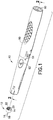
- the subject invention provides a medical injector 10 which allows for dose setting after autoreconstitution and prior to autoplunger drive.
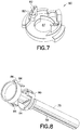
- the medical injector 10 is configured to permit mounting of a needle 12 thereto.
- the medical injector 10 may be in the form of any medical injector, such as a syringe or pen injector, which is capable of reconstituting mixable components accommodated therein into an administrable liquid.
- the medical injector 10 may be a single- or multiple-dose device.
- the needle 12 may be in any form.
- the needle 12 includes a hub 14 to which is affixed a needle cannula 16.
- Distal end 18 of the needle cannula 16 is formed for insertion into a patient, while proximal end 20 may optimally be sharpened.
- the hub 14 may be formed with mounting features 22, such as threads, for mounting onto the medical injector 10, as described below.
- distal shall refer to a direction toward a patient during use
- proximal shall refer to a direction away from a patient during use
- the medical injector 10 includes a body 24 which may be formed of one or more components.
- the medical injector 10 also includes a needle mounting surface 26 having features 28 for mounting the needle 12 thereto.
- the features 28 may be of any known type for mounting the needle 12 including features for creating a cooperating mechanical lock with the needle 12, particularly for cooperating with the mounting features 22, such as threads, bayonet lock members, detents, grooves, and so forth, and/or frictional engagement with the hub 14, such as through a tapered Luer configuration.
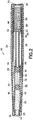
- the medical injector 10 is an autoreconstitution device which, as shown in Figure 2 , includes at least first and second mixable components 30, 32 in an initial state.
- a reservoir 34 is disposed in the body 24 for accommodating the first and second mixable components 30, 32.
- At least one stopper 36 is associated with the reservoir 34 configured such that distal advancement of the stopper 36 over a predetermined distance shall cause mixing of the first and second mixable components 30, 32. Any known arrangement for allowing such mixing may be utilized.
- the first and second mixable components 30, 32 may be separated by a secondary stopper 38.
- the secondary stopper 38 divides the reservoir 34 into first and second chambers 40, 42, respectively, accommodating the first and second mixable components 30, 32.
- a septum 44 seals off the distal end of the first chamber 40, while the stopper 36 is positioned to seal off the proximal end of the second chamber 42.
- the dry mixable component is located in the first chamber 40.
- One or more by-pass channels 46 are formed in the wall of the reservoir 34.
- the secondary stopper 38 is located at least partially proximally of the by-pass channels 46 so as to define a seal between the first and second chambers 40, 42 and to define a seal between the second chamber 42 and the by-pass channels 46.
- the second chamber 42 comes into communication with the by-pass channels 46, thus allowing the second mixable component 30 to be urged into the first chamber 40 with further distal movement of the stopper 36.
- the second chamber 42 is collapsed with none or substantially none of the second mixable component 32 remaining therein.
- the secondary stopper 38 is located so as to define a seal between the first chamber 40 and the by-pass channels 46.
- the first and second mixable components 30, 32 are mixed within the first chamber 40, such as through agitation of the medical injector 10, so as to produce an injectable solution, ready for injection.
- the first mixable component 30 may be dry (e.g., a powder or granular substance) and/or a liquid (e.g., flowable (slurry or liquid)).
- the second mixable component 32 is preferably only a wet flowable component such as a liquid or slurry.
- a spring 56 may be provided to cause plunger 58 to drive forward.
- the plunger 58 acts against the stopper 36 in achieving autoreconstitution of the first and second mixable components 30, 32, as described above.
- the spring 56 may act, via the plunger 58, to distally drive the stopper 36 from the initial first position of Figure 2 .
- the spring 56 may be of any type, including coil or compression spring. Other types of biasing elements may be also utilized.
- the plunger 58 is retained in the first position of Figure 2 by any known manner of releasable retaining mechanism.
- a trigger may be provided to release the retaining mechanism to cause autoreconstitution and advancement of the plunger 58.
- U.S. Patent No. 6,793,646 to Giambatista et al. discloses an injector with trigger-activated autoreconstitution where autoreconstitution is activated by collapsing together two body parts of the injector. The collapsing effect causes release of the plunger and autoreconstitution.
- a trigger 60 may be slidably disposed in the body 24, and the plunger 58 may include one or more deflectable latch tabs 62.
- the latch tabs 62 In the initial first state of Figure 2 , the latch tabs 62 have free ends 64 which interferingly engage ledges 66. Interengagement between the latch tabs 66 and the ledges 66 retains the plunger 58 in the first state against force of movement of the spring 56.
- the trigger 60 includes one or more arms 68 which define a smaller diameter than the latch tabs 62. With sufficient distal advancement of the trigger 60, e.g. being caused by force being applied to proximal end 70 thereof, the arms 68 engage the latch tabs 62 and cause inward deflection thereof. With inward deflection of the latch tabs 62, the spring 56 is free to drive the plunger 58 distally and engage the stopper 36 in causing autoreconstitution.
- releasable retaining arrangements and triggers may be utilized for retaining the plunger 58 in the initial state and causing release therefrom.
- a bayonet lock-type releasable retaining arrangement may be utilized which is triggered by rotating one or more portions of the body of the medical injector 10 or rotating an additional component, such as a dose setting knob.
- Copending applications PCT Application No. _(Attorney Reference No. P-8635.70 (102-747 PCT)) and PCT Application No. _(Attorney Reference No. P-8625.70 (102-745 PCT)) disclose releasable retainer arrangements which are triggered by rotation to permit plunger advancement.
- the spring 56 is configured to advance the plunger 58 a predetermined extent of movement.
- a second releasable retainer 70 is provided to intercept the plunger 58 along its course of advancement in stopping the plunger 58 at a second position.
- the second position is located so as to prevent the plunger 58 from traversing the entire predetermined extent of movement.
- the second position is located so as to permit the plunger 58 to traverse a sufficient distance to drive the stopper 36 a sufficient distance to achieve reconstitution.
- the second releasable retainer 70 may include stop block 72 having an opening 74 formed therethrough to permit passage of plunger stem 76 of the plunger 58.
- the plunger stem 76 is aligned to engage the stopper 36 during use.
- the opening 74 is formed larger than the cross-section of the plunger stem 76 such that the stop block 72 is axially shiftable relative to the plunger stem 76 between blocking and open states.
- the stop block 72 is axially shiftable in a direction transverse to the direction of movement of the plunger 58.
- the stop block 72 In the blocking state, as shown in Figures 3 and 4 , the stop block 72 is formed to interferingly engage stop member 78 formed on the plunger 58 with a portion of the plunger stem 76 passing through the opening 74. In the open state, as shown in Figure 5 , the stop block 72 permits the stop member 78 to pass through the opening 74 with the plunger stem 76.
- the stop member 78 is axially spaced from the stop block 72.
- the plunger 58 With the plunger 58 being released from the first state, the plunger 58 axially advances with the plunger stem 76 passing through the opening 74. During this movement, the plunger 58 advances the stopper 36 at least a sufficient distance to achieve reconstitution.
- the stop block 72 is initially in the blocking state. Eventual distal advancement of the plunger 58 causes the stop member 78 to engage the stop block 72, as shown in Figure 3 . The point of engagement between the stop member 78 and the stop block 72 is reached prior to the entire predetermined extent of movement of the plunger 58 for which the spring 56 is configured. Thus, the stop block 72 retains the plunger 58 in this second state against force of movement of the spring 56. Axial shift of the stop block 72 moves the stop block 72 to the open state thus releasing the plunger 58 from the second state.
- the stop block 72 is positioned to locate the second state at minimally a distance permitting autoreconstitution to be achieved with the plunger 58 moving from the first state to the second state.
- reconstitution of the first and second mixable components 30, 32 is conducted without the needle 12 mounted to the medical injector 10.
- the reservoir 34 is not vented during the mixing. In this manner, the mixed components may be maximally compressed under force of the spring 56.
- the reservoir 34 With mounting of the needle 12 onto the medical injector 10, the reservoir 34 is vented thus permitting further distal advancement of the plunger 58. This secondary distal advancement may assist in priming a needle for use. It is preferred that autoreconstitution be completed prior to the stop member 78 coming into engagement with the stop block 72.
- the reservoir 34 is vented, thus reducing the trapped volume therein. This permits the stopper 36 to be further advanced under force of movement of the spring 56 till trapped gases are purged. It is preferred that the stop member 78 come into engagement with the stop block 72 upon this secondary distal advancement.
- Dose selection may be conducted upon initiation, during or after autoreconstituion. Any configuration for dose selection may be utilized.
- a dose ring 80 may be provided with a plurality of axially and radially spaced-apart abutment surfaces 82 which represent different dose sizes.
- the abutment surfaces 82 are axially alignable with one or more engagement surfaces 84 formed on the plunger 58.
- One or more tabs 86 may extend from the plunger 58 on which the engagement surfaces 84 may be defined. It is preferred that the tabs 86 be formed to not be passable through the opening 74 of the stop block 72 in either the blocking or open states.
- the dose ring 80 includes an aperture 87 which permits passage of the plunger stem 76 and the stop member 78 therethrough.
- the engagement surfaces 84 may be axially aligned with different of the abutment surfaces 82 thus allowing for dose selection.
- the engagement surfaces 84 are spaced from the abutment surfaces 82 with the plunger 58 being retained in the second state.
- the distance between the engagement surfaces 84, located with the plunger 58 being in the second state, and the selected of the abutments surfaces 82 will dictate the stroke length of the plunger 58 during injection and, thus, dictate the dose size. A greater distance will provide a larger dose and, conversely, a smaller distance will provide a smaller dose.
- the plunger 58 under force of movement of the spring 56, is advanced distally and, in turn, forces the stopper 36 distally to urge the injectable solution into the patient. Interengagement of the selected abutment surfaces 82 and the engagement surfaces 84 limits the distal movement to produce the selected dose. Movement of the plunger 58 is automated under force of the spring 56 thus producing an autoplunger drive.
- the plunger 58 may be caused to rotate by various configurations.
- one of more of the tabs 86 may be nested in slots 88 formed in an outer body potion 90. With rotation of the outer body portion 90, corresponding rotation of the plunger 58 may be achieved.
- Indicia 91 ( Figure 1 ) may be located on the medical injector 10 to assist in dose setting.
- the stop block 72 is axially shifted through activation of second trigger 92.
- the second trigger 92 is an inwardly-displaceable button formed on the body 24 and aligned to shift the stop block 72 from the blocking state to the open state with inward displacement.
- One or more intermediary components may be utilized which transmit force from inward displacement of the second trigger 92 to the stop block 72.
- the dose ring 80 have retaining clips 94 formed to snap receive the stop block 72 with the opening 74 and the aperture 87 being aligned so as to both permit passage therethrough of the plunger stem 76.
- the dose ring 80 is formed to permit axial shifting of the stop block 72 between the blocking and open states.
- a spring arm 96 may extend from the dose ring 80 to bias the stop block 72 to the blocking state. Axial movement of the stop block 72 to the open state is thus against biasing force generated by the spring arm 96.
- Dose selection may be conducted at any time prior to release of the plunger 58 from the second state. It is preferred that once a dose is set, axial alignment of the selected abutment surfaces 82 and the engagement surfaces 84 be maintained. Such an arrangement is disclosed in U.S. Patent No. 6,793,646 . As shown therein, one or more tabs may be used to engage teeth or channels in a ratchet fashion.
- one or more of the tabs 86 may be initially radially positioned to block the second trigger 92 from activation prior to dose selection with the plunger 58 being in the second state. In this manner, the second trigger 92 is blocked from inward displacement and, thus, is blocked from shifting the stop block 72 from the blocking state to the open state. With radial adjustment of the tabs 86 in selecting a dose, the second trigger 92 may be freed for activation.
- a medical injector is provided with two distinct triggers for causing autoreconstitution and autoplunger drive, respectively.
- dose selection is permitted after autoreconstitution and prior to automated plunger drive.
Landscapes
- Health & Medical Sciences (AREA)
- Vascular Medicine (AREA)
- Engineering & Computer Science (AREA)
- Anesthesiology (AREA)
- Biomedical Technology (AREA)
- Heart & Thoracic Surgery (AREA)
- Hematology (AREA)
- Life Sciences & Earth Sciences (AREA)
- Animal Behavior & Ethology (AREA)
- General Health & Medical Sciences (AREA)
- Public Health (AREA)
- Veterinary Medicine (AREA)
- Infusion, Injection, And Reservoir Apparatuses (AREA)
Applications Claiming Priority (3)
| Application Number | Priority Date | Filing Date | Title |
|---|---|---|---|
| US19246708P | 2008-09-18 | 2008-09-18 | |
| US19238908P | 2008-09-18 | 2008-09-18 | |
| PCT/US2009/057485 WO2010033808A2 (en) | 2008-09-18 | 2009-09-18 | Medical injector with post-autoreconstitution dose setting and autoplunger drive |
Publications (3)
| Publication Number | Publication Date |
|---|---|
| EP2328640A2 EP2328640A2 (en) | 2011-06-08 |
| EP2328640A4 EP2328640A4 (en) | 2013-05-01 |
| EP2328640B1 true EP2328640B1 (en) | 2016-12-21 |
Family
ID=42040160
Family Applications (1)
| Application Number | Title | Priority Date | Filing Date |
|---|---|---|---|
| EP09815269.7A Active EP2328640B1 (en) | 2008-09-18 | 2009-09-18 | Medical injector with post-autoreconstitution dose setting and autoplunger drive |
Country Status (6)
| Country | Link |
|---|---|
| US (2) | US8500682B2 (enExample) |
| EP (1) | EP2328640B1 (enExample) |
| JP (1) | JP2012502765A (enExample) |
| CN (1) | CN102186520B (enExample) |
| ES (1) | ES2619526T3 (enExample) |
| WO (1) | WO2010033808A2 (enExample) |
Families Citing this family (10)
| Publication number | Priority date | Publication date | Assignee | Title |
|---|---|---|---|---|
| EP3545987B1 (en) * | 2008-09-18 | 2021-02-17 | Becton, Dickinson and Company | Medical injector with coupled body portions |
| CN102202710B (zh) * | 2008-09-18 | 2013-08-21 | 贝克顿·迪金森公司 | 具有可旋转主体部的医用注射器 |
| US9005160B2 (en) * | 2009-10-26 | 2015-04-14 | Shl Group Ab | Medicament delivery device |
| GB201020472D0 (en) | 2010-12-02 | 2011-01-19 | Oval Medical Technologies Ltd | A drive assembly for an autoinjector |
| US20150217058A1 (en) | 2012-09-24 | 2015-08-06 | Enable Injections, Llc | Medical vial and injector assemblies and methods of use |
| EP4144390A3 (en) | 2013-06-18 | 2023-07-12 | Enable Injections, Inc. | Vial transfer and injection apparatus and method |
| EP3041546B1 (en) | 2013-09-03 | 2021-01-13 | Sanofi | Assembly for a drug delivery device |
| USD866757S1 (en) | 2016-03-11 | 2019-11-12 | Millennium Pharmaceuticals, Inc. | Autoinjector |
| MY203391A (en) * | 2017-06-29 | 2024-06-26 | Ascendis Pharma As | Auto injector with reconstitution handling support |
| DE102019200563A1 (de) * | 2019-01-17 | 2020-07-23 | Lts Lohmann Therapie-Systeme Ag | Applikator |
Family Cites Families (12)
| Publication number | Priority date | Publication date | Assignee | Title |
|---|---|---|---|---|
| US4689042A (en) * | 1985-05-20 | 1987-08-25 | Survival Technology, Inc. | Automatic medicament ingredient mixing and injecting apparatus |
| US5584815A (en) * | 1993-04-02 | 1996-12-17 | Eli Lilly And Company | Multi-cartridge medication injection device |
| FR2741810B1 (fr) * | 1995-11-30 | 1998-02-20 | Soc Et Et D Applic Tech Sedat | Seringue pour l'injection d'un melange extemporane |
| US6203530B1 (en) * | 1997-01-28 | 2001-03-20 | Pos-T-Vac, Inc. | Auto-injection device |
| US6096002A (en) * | 1998-11-18 | 2000-08-01 | Bioject, Inc. | NGAS powered self-resetting needle-less hypodermic jet injection apparatus and method |
| ATE308354T1 (de) * | 1999-04-16 | 2005-11-15 | Becton Dickinson Co | Stiftförmiger injektor mit merkmalen zur automatischen substanzkombination |
| US7621887B2 (en) | 2000-10-10 | 2009-11-24 | Meridian Medical Technologies, Inc. | Wet/dry automatic injector assembly |
| DE10129585A1 (de) | 2001-06-20 | 2003-01-09 | Disetronic Licensing Ag | Vorrichtung für eine dosierte Verabreichung eines injizierbaren Produkts |
| EP1838366B1 (en) * | 2004-11-24 | 2013-03-13 | Becton, Dickinson and Company | Automatic reconstitution injector device |
| BRPI0607012A2 (pt) | 2005-01-25 | 2009-12-01 | Novo Nordisk As | dispositivo de injeção |
| US7407494B2 (en) * | 2005-01-31 | 2008-08-05 | Bostroem Anders | Device for delivering medicament |
| WO2007131013A1 (en) * | 2006-05-03 | 2007-11-15 | Antares Pharma, Inc. | Two-stage reconstituting injector |
-
2009
- 2009-09-18 CN CN2009801415112A patent/CN102186520B/zh active Active
- 2009-09-18 US US13/119,266 patent/US8500682B2/en active Active
- 2009-09-18 JP JP2011527999A patent/JP2012502765A/ja active Pending
- 2009-09-18 WO PCT/US2009/057485 patent/WO2010033808A2/en not_active Ceased
- 2009-09-18 ES ES09815269.7T patent/ES2619526T3/es active Active
- 2009-09-18 EP EP09815269.7A patent/EP2328640B1/en active Active
-
2013
- 2013-06-12 US US13/916,101 patent/US10034980B2/en active Active
Also Published As
| Publication number | Publication date |
|---|---|
| CN102186520A (zh) | 2011-09-14 |
| ES2619526T3 (es) | 2017-06-26 |
| CN102186520B (zh) | 2013-12-11 |
| US20120041367A1 (en) | 2012-02-16 |
| WO2010033808A3 (en) | 2010-07-01 |
| US20170113003A9 (en) | 2017-04-27 |
| US20130274706A1 (en) | 2013-10-17 |
| EP2328640A4 (en) | 2013-05-01 |
| JP2012502765A (ja) | 2012-02-02 |
| US8500682B2 (en) | 2013-08-06 |
| EP2328640A2 (en) | 2011-06-08 |
| WO2010033808A2 (en) | 2010-03-25 |
| US10034980B2 (en) | 2018-07-31 |
Similar Documents
| Publication | Publication Date | Title |
|---|---|---|
| EP2328640B1 (en) | Medical injector with post-autoreconstitution dose setting and autoplunger drive | |
| EP3545987B1 (en) | Medical injector with coupled body portions | |
| EP2326370B1 (en) | Medical injector with slidable sleeve activation | |
| EP2328637B1 (en) | Needle mounting feature for ensuring proper reconstitution sequence | |
| EP2331176B1 (en) | Medical injector with rotatable body portions | |
| JP5749646B2 (ja) | ボタン起動を備えた医療用注入器 | |
| JP2012502765A5 (enExample) | ||
| WO2012010832A1 (en) | Injection device | |
| US20150314080A1 (en) | Needle Mounting Feature for Ensuring Proper Reconstitution Sequence |
Legal Events
| Date | Code | Title | Description |
|---|---|---|---|
| PUAI | Public reference made under article 153(3) epc to a published international application that has entered the european phase |
Free format text: ORIGINAL CODE: 0009012 |
|
| 17P | Request for examination filed |
Effective date: 20110316 |
|
| AK | Designated contracting states |
Kind code of ref document: A2 Designated state(s): AT BE BG CH CY CZ DE DK EE ES FI FR GB GR HR HU IE IS IT LI LT LU LV MC MK MT NL NO PL PT RO SE SI SK SM TR |
|
| AX | Request for extension of the european patent |
Extension state: AL BA RS |
|
| DAX | Request for extension of the european patent (deleted) | ||
| A4 | Supplementary search report drawn up and despatched |
Effective date: 20130402 |
|
| RIC1 | Information provided on ipc code assigned before grant |
Ipc: A61M 5/20 20060101AFI20130325BHEP Ipc: A61M 5/315 20060101ALI20130325BHEP |
|
| 17Q | First examination report despatched |
Effective date: 20140305 |
|
| REG | Reference to a national code |
Ref country code: DE Ref legal event code: R079 Ref document number: 602009043283 Country of ref document: DE Free format text: PREVIOUS MAIN CLASS: A61M0005200000 Ipc: A61M0005240000 |
|
| RIC1 | Information provided on ipc code assigned before grant |
Ipc: A61M 5/20 20060101ALI20160510BHEP Ipc: A61M 5/31 20060101ALI20160510BHEP Ipc: A61M 5/24 20060101AFI20160510BHEP Ipc: A61M 5/315 20060101ALI20160510BHEP |
|
| GRAP | Despatch of communication of intention to grant a patent |
Free format text: ORIGINAL CODE: EPIDOSNIGR1 |
|
| INTG | Intention to grant announced |
Effective date: 20160713 |
|
| GRAS | Grant fee paid |
Free format text: ORIGINAL CODE: EPIDOSNIGR3 |
|
| STAA | Information on the status of an ep patent application or granted ep patent |
Free format text: STATUS: GRANT OF PATENT IS INTENDED |
|
| GRAA | (expected) grant |
Free format text: ORIGINAL CODE: 0009210 |
|
| STAA | Information on the status of an ep patent application or granted ep patent |
Free format text: STATUS: THE PATENT HAS BEEN GRANTED |
|
| RAP1 | Party data changed (applicant data changed or rights of an application transferred) |
Owner name: BECTON, DICKINSON AND COMPANY |
|
| AK | Designated contracting states |
Kind code of ref document: B1 Designated state(s): AT BE BG CH CY CZ DE DK EE ES FI FR GB GR HR HU IE IS IT LI LT LU LV MC MK MT NL NO PL PT RO SE SI SK SM TR |
|
| REG | Reference to a national code |
Ref country code: GB Ref legal event code: FG4D |
|
| REG | Reference to a national code |
Ref country code: CH Ref legal event code: EP |
|
| REG | Reference to a national code |
Ref country code: IE Ref legal event code: FG4D |
|
| REG | Reference to a national code |
Ref country code: AT Ref legal event code: REF Ref document number: 854937 Country of ref document: AT Kind code of ref document: T Effective date: 20170115 |
|
| REG | Reference to a national code |
Ref country code: DE Ref legal event code: R096 Ref document number: 602009043283 Country of ref document: DE |
|
| PG25 | Lapsed in a contracting state [announced via postgrant information from national office to epo] |
Ref country code: LV Free format text: LAPSE BECAUSE OF FAILURE TO SUBMIT A TRANSLATION OF THE DESCRIPTION OR TO PAY THE FEE WITHIN THE PRESCRIBED TIME-LIMIT Effective date: 20161221 |
|
| REG | Reference to a national code |
Ref country code: LT Ref legal event code: MG4D |
|
| REG | Reference to a national code |
Ref country code: NL Ref legal event code: MP Effective date: 20161221 |
|
| PG25 | Lapsed in a contracting state [announced via postgrant information from national office to epo] |
Ref country code: LT Free format text: LAPSE BECAUSE OF FAILURE TO SUBMIT A TRANSLATION OF THE DESCRIPTION OR TO PAY THE FEE WITHIN THE PRESCRIBED TIME-LIMIT Effective date: 20161221 Ref country code: GR Free format text: LAPSE BECAUSE OF FAILURE TO SUBMIT A TRANSLATION OF THE DESCRIPTION OR TO PAY THE FEE WITHIN THE PRESCRIBED TIME-LIMIT Effective date: 20170322 Ref country code: SE Free format text: LAPSE BECAUSE OF FAILURE TO SUBMIT A TRANSLATION OF THE DESCRIPTION OR TO PAY THE FEE WITHIN THE PRESCRIBED TIME-LIMIT Effective date: 20161221 Ref country code: NO Free format text: LAPSE BECAUSE OF FAILURE TO SUBMIT A TRANSLATION OF THE DESCRIPTION OR TO PAY THE FEE WITHIN THE PRESCRIBED TIME-LIMIT Effective date: 20170321 |
|
| REG | Reference to a national code |
Ref country code: AT Ref legal event code: MK05 Ref document number: 854937 Country of ref document: AT Kind code of ref document: T Effective date: 20161221 |
|
| PG25 | Lapsed in a contracting state [announced via postgrant information from national office to epo] |
Ref country code: HR Free format text: LAPSE BECAUSE OF FAILURE TO SUBMIT A TRANSLATION OF THE DESCRIPTION OR TO PAY THE FEE WITHIN THE PRESCRIBED TIME-LIMIT Effective date: 20161221 Ref country code: FI Free format text: LAPSE BECAUSE OF FAILURE TO SUBMIT A TRANSLATION OF THE DESCRIPTION OR TO PAY THE FEE WITHIN THE PRESCRIBED TIME-LIMIT Effective date: 20161221 |
|
| REG | Reference to a national code |
Ref country code: ES Ref legal event code: FG2A Ref document number: 2619526 Country of ref document: ES Kind code of ref document: T3 Effective date: 20170626 |
|
| PG25 | Lapsed in a contracting state [announced via postgrant information from national office to epo] |
Ref country code: NL Free format text: LAPSE BECAUSE OF FAILURE TO SUBMIT A TRANSLATION OF THE DESCRIPTION OR TO PAY THE FEE WITHIN THE PRESCRIBED TIME-LIMIT Effective date: 20161221 |
|
| PG25 | Lapsed in a contracting state [announced via postgrant information from national office to epo] |
Ref country code: EE Free format text: LAPSE BECAUSE OF FAILURE TO SUBMIT A TRANSLATION OF THE DESCRIPTION OR TO PAY THE FEE WITHIN THE PRESCRIBED TIME-LIMIT Effective date: 20161221 Ref country code: IS Free format text: LAPSE BECAUSE OF FAILURE TO SUBMIT A TRANSLATION OF THE DESCRIPTION OR TO PAY THE FEE WITHIN THE PRESCRIBED TIME-LIMIT Effective date: 20170421 Ref country code: RO Free format text: LAPSE BECAUSE OF FAILURE TO SUBMIT A TRANSLATION OF THE DESCRIPTION OR TO PAY THE FEE WITHIN THE PRESCRIBED TIME-LIMIT Effective date: 20161221 Ref country code: CZ Free format text: LAPSE BECAUSE OF FAILURE TO SUBMIT A TRANSLATION OF THE DESCRIPTION OR TO PAY THE FEE WITHIN THE PRESCRIBED TIME-LIMIT Effective date: 20161221 Ref country code: SK Free format text: LAPSE BECAUSE OF FAILURE TO SUBMIT A TRANSLATION OF THE DESCRIPTION OR TO PAY THE FEE WITHIN THE PRESCRIBED TIME-LIMIT Effective date: 20161221 |
|
| REG | Reference to a national code |
Ref country code: FR Ref legal event code: PLFP Year of fee payment: 9 |
|
| PG25 | Lapsed in a contracting state [announced via postgrant information from national office to epo] |
Ref country code: BG Free format text: LAPSE BECAUSE OF FAILURE TO SUBMIT A TRANSLATION OF THE DESCRIPTION OR TO PAY THE FEE WITHIN THE PRESCRIBED TIME-LIMIT Effective date: 20170321 Ref country code: AT Free format text: LAPSE BECAUSE OF FAILURE TO SUBMIT A TRANSLATION OF THE DESCRIPTION OR TO PAY THE FEE WITHIN THE PRESCRIBED TIME-LIMIT Effective date: 20161221 Ref country code: PL Free format text: LAPSE BECAUSE OF FAILURE TO SUBMIT A TRANSLATION OF THE DESCRIPTION OR TO PAY THE FEE WITHIN THE PRESCRIBED TIME-LIMIT Effective date: 20161221 Ref country code: SM Free format text: LAPSE BECAUSE OF FAILURE TO SUBMIT A TRANSLATION OF THE DESCRIPTION OR TO PAY THE FEE WITHIN THE PRESCRIBED TIME-LIMIT Effective date: 20161221 Ref country code: BE Free format text: LAPSE BECAUSE OF FAILURE TO SUBMIT A TRANSLATION OF THE DESCRIPTION OR TO PAY THE FEE WITHIN THE PRESCRIBED TIME-LIMIT Effective date: 20161221 Ref country code: PT Free format text: LAPSE BECAUSE OF FAILURE TO SUBMIT A TRANSLATION OF THE DESCRIPTION OR TO PAY THE FEE WITHIN THE PRESCRIBED TIME-LIMIT Effective date: 20170421 |
|
| REG | Reference to a national code |
Ref country code: DE Ref legal event code: R097 Ref document number: 602009043283 Country of ref document: DE |
|
| PLBE | No opposition filed within time limit |
Free format text: ORIGINAL CODE: 0009261 |
|
| STAA | Information on the status of an ep patent application or granted ep patent |
Free format text: STATUS: NO OPPOSITION FILED WITHIN TIME LIMIT |
|
| 26N | No opposition filed |
Effective date: 20170922 |
|
| PG25 | Lapsed in a contracting state [announced via postgrant information from national office to epo] |
Ref country code: DK Free format text: LAPSE BECAUSE OF FAILURE TO SUBMIT A TRANSLATION OF THE DESCRIPTION OR TO PAY THE FEE WITHIN THE PRESCRIBED TIME-LIMIT Effective date: 20161221 |
|
| PG25 | Lapsed in a contracting state [announced via postgrant information from national office to epo] |
Ref country code: SI Free format text: LAPSE BECAUSE OF FAILURE TO SUBMIT A TRANSLATION OF THE DESCRIPTION OR TO PAY THE FEE WITHIN THE PRESCRIBED TIME-LIMIT Effective date: 20161221 |
|
| REG | Reference to a national code |
Ref country code: CH Ref legal event code: PL |
|
| PG25 | Lapsed in a contracting state [announced via postgrant information from national office to epo] |
Ref country code: MC Free format text: LAPSE BECAUSE OF FAILURE TO SUBMIT A TRANSLATION OF THE DESCRIPTION OR TO PAY THE FEE WITHIN THE PRESCRIBED TIME-LIMIT Effective date: 20161221 |
|
| REG | Reference to a national code |
Ref country code: IE Ref legal event code: MM4A |
|
| PG25 | Lapsed in a contracting state [announced via postgrant information from national office to epo] |
Ref country code: LU Free format text: LAPSE BECAUSE OF NON-PAYMENT OF DUE FEES Effective date: 20170918 |
|
| PG25 | Lapsed in a contracting state [announced via postgrant information from national office to epo] |
Ref country code: IE Free format text: LAPSE BECAUSE OF NON-PAYMENT OF DUE FEES Effective date: 20170918 Ref country code: CH Free format text: LAPSE BECAUSE OF NON-PAYMENT OF DUE FEES Effective date: 20170930 Ref country code: LI Free format text: LAPSE BECAUSE OF NON-PAYMENT OF DUE FEES Effective date: 20170930 |
|
| REG | Reference to a national code |
Ref country code: FR Ref legal event code: PLFP Year of fee payment: 10 |
|
| PG25 | Lapsed in a contracting state [announced via postgrant information from national office to epo] |
Ref country code: MT Free format text: LAPSE BECAUSE OF NON-PAYMENT OF DUE FEES Effective date: 20170918 |
|
| PG25 | Lapsed in a contracting state [announced via postgrant information from national office to epo] |
Ref country code: HU Free format text: LAPSE BECAUSE OF FAILURE TO SUBMIT A TRANSLATION OF THE DESCRIPTION OR TO PAY THE FEE WITHIN THE PRESCRIBED TIME-LIMIT; INVALID AB INITIO Effective date: 20090918 |
|
| PG25 | Lapsed in a contracting state [announced via postgrant information from national office to epo] |
Ref country code: CY Free format text: LAPSE BECAUSE OF NON-PAYMENT OF DUE FEES Effective date: 20161221 |
|
| PG25 | Lapsed in a contracting state [announced via postgrant information from national office to epo] |
Ref country code: MK Free format text: LAPSE BECAUSE OF FAILURE TO SUBMIT A TRANSLATION OF THE DESCRIPTION OR TO PAY THE FEE WITHIN THE PRESCRIBED TIME-LIMIT Effective date: 20161221 |
|
| PG25 | Lapsed in a contracting state [announced via postgrant information from national office to epo] |
Ref country code: TR Free format text: LAPSE BECAUSE OF FAILURE TO SUBMIT A TRANSLATION OF THE DESCRIPTION OR TO PAY THE FEE WITHIN THE PRESCRIBED TIME-LIMIT Effective date: 20161221 |
|
| PGFP | Annual fee paid to national office [announced via postgrant information from national office to epo] |
Ref country code: DE Payment date: 20250820 Year of fee payment: 17 |
|
| PGFP | Annual fee paid to national office [announced via postgrant information from national office to epo] |
Ref country code: IT Payment date: 20250820 Year of fee payment: 17 |
|
| PGFP | Annual fee paid to national office [announced via postgrant information from national office to epo] |
Ref country code: GB Payment date: 20250822 Year of fee payment: 17 |
|
| PGFP | Annual fee paid to national office [announced via postgrant information from national office to epo] |
Ref country code: FR Payment date: 20250820 Year of fee payment: 17 |
|
| PGFP | Annual fee paid to national office [announced via postgrant information from national office to epo] |
Ref country code: ES Payment date: 20251001 Year of fee payment: 17 |