EP2328506B1 - Appareil orthodontique auto-ligaturant et à profil bas avec attache - Google Patents
Appareil orthodontique auto-ligaturant et à profil bas avec attache Download PDFInfo
- Publication number
- EP2328506B1 EP2328506B1 EP09790832.1A EP09790832A EP2328506B1 EP 2328506 B1 EP2328506 B1 EP 2328506B1 EP 09790832 A EP09790832 A EP 09790832A EP 2328506 B1 EP2328506 B1 EP 2328506B1
- Authority
- EP
- European Patent Office
- Prior art keywords
- appliance
- archwire
- archwire slot
- clip
- tooth
- Prior art date
- Legal status (The legal status is an assumption and is not a legal conclusion. Google has not performed a legal analysis and makes no representation as to the accuracy of the status listed.)
- Not-in-force
Links
Images


Classifications
-
- A—HUMAN NECESSITIES
- A61—MEDICAL OR VETERINARY SCIENCE; HYGIENE
- A61C—DENTISTRY; APPARATUS OR METHODS FOR ORAL OR DENTAL HYGIENE
- A61C7/00—Orthodontics, i.e. obtaining or maintaining the desired position of teeth, e.g. by straightening, evening, regulating, separating, or by correcting malocclusions
- A61C7/12—Brackets; Arch wires; Combinations thereof; Accessories therefor
- A61C7/28—Securing arch wire to bracket
- A61C7/30—Securing arch wire to bracket by resilient means; Dispensers therefor
-
- A—HUMAN NECESSITIES
- A61—MEDICAL OR VETERINARY SCIENCE; HYGIENE
- A61C—DENTISTRY; APPARATUS OR METHODS FOR ORAL OR DENTAL HYGIENE
- A61C7/00—Orthodontics, i.e. obtaining or maintaining the desired position of teeth, e.g. by straightening, evening, regulating, separating, or by correcting malocclusions
- A61C7/12—Brackets; Arch wires; Combinations thereof; Accessories therefor
- A61C7/14—Brackets; Fixing brackets to teeth
- A61C7/145—Lingual brackets
-
- Y—GENERAL TAGGING OF NEW TECHNOLOGICAL DEVELOPMENTS; GENERAL TAGGING OF CROSS-SECTIONAL TECHNOLOGIES SPANNING OVER SEVERAL SECTIONS OF THE IPC; TECHNICAL SUBJECTS COVERED BY FORMER USPC CROSS-REFERENCE ART COLLECTIONS [XRACs] AND DIGESTS
- Y10—TECHNICAL SUBJECTS COVERED BY FORMER USPC
- Y10T—TECHNICAL SUBJECTS COVERED BY FORMER US CLASSIFICATION
- Y10T29/00—Metal working
- Y10T29/49—Method of mechanical manufacture
- Y10T29/49567—Dental appliance making
- Y10T29/49568—Orthodontic device making
Definitions
- This invention broadly relates to intra-oral appliances that are used during the course of orthodontic treatment. More particularly, the present invention relates to self-ligating orthodontic appliances having one or more clips for releasably retaining an archwire in an archwire slot of the appliance.
- Orthodontic therapy is a specialized type of treatment within the field of dentistry, and involves of repositioning of malpositioned teeth to orthodontically correct locations. Orthodontic therapy often enhances the aesthetic appearance of the teeth, especially in instances when the patient's front teeth are malpositioned or crooked. Orthodontic treatment can also improve the patient's occlusion so that opposed teeth function better with each other during the times that the patient is chewing.
- Braces Many types of orthodontic treatment programs involve the use of a set of tiny appliances and archwires that are commonly known collectively as "braces".
- small appliances known as brackets are fixed to the patient's anterior, cuspid and bicuspid teeth, and an archwire is inserted into a slot of each bracket.
- the archwire forms a track to guide movement of the teeth to desired positions.
- End sections of the archwires are often captured in tiny appliances known as buccal tubes that are fixed to the patient's molar teeth.
- Brackets Many orthodontic brackets have small wings known as "tiewings" that are connected to a body of the bracket. Once the bracket has been attached to a tooth and an archwire has been placed in the archwire slot of the bracket, a ligature is coupled to the bracket in order to retain the archwire in the archwire slot.
- a commercially available orthodontic ligature is a small, elastomeric O-ring that is installed by stretching the O-ring along a path behind the tiewings and over the facial side of the archwire.
- the latch may comprise a movable clip, spring member, sliding cover, shutter, bail or other structure that is connected to the bracket body for retaining the archwire in the archwire slot.
- U.S. Patent No. 6,776,614 describes a system of customized orthodontic brackets and archwires. This patent further describes designing the brackets on a computer as a combination of three-dimensional virtual objects including a virtual bracket bonding pad and a virtual bracket body retrieved from a library of virtual bracket bodies.
- the virtual brackets can be represented as a file containing digital shape data that can be exported to a rapid prototype fabrication device. The rapid prototype fabrication device can be used to make models of the brackets which, in turn, are then used to form molds for subsequent casting of the brackets.
- US 5174754 describes an orthodontic bracket having a slot adapted to receive a T-shaped archwire.
- the body includes tie wings each having a cantilevered notch and a locking arm.
- US2004/0086826 describes a self-ligating appliance adapted for use with a patient's molar teeth.
- the appliance includes a body featuring discrete mesial and distal archwire guides.
- the appliance further includes a latch for releasably retaining an archwire in an archwire slot, which can take the form of a mesial and a distal clip.
- EP 1234549 describes a self-ligating appliance having a slot that is open towards a chewing plane, purportedly so that an arch wire may be inserted into the slot from the occlusal side in a safer manner.
- a pivotable spring or an elastic ligature may be used to retain the archwire in the slot.
- Orthodontic appliances including brackets having an overall, generally small or low profile are often desired by practitioners for use in treatment. Such low profile appliances are less likely to contact other teeth or appliances in the patient's oral cavity, an important advantage in certain instances when the teeth are not initially positioned in substantial alignment relative to each other. Low profile appliances are also less likely to impinge on the patient's oral tissue and cause irritation of the same.
- the present invention is directed to a custom, self-ligating orthodontic appliance that comprises a base having a configuration matching the configuration of a specific tooth of a specific patient, as defined in claim 1.
- the appliance also includes a body integrally connected to the base, the body including an elongated archwire slot extending in a generally mesial-distal direction.
- the appliance additionally includes a latch coupled to the body for releasably retaining an archwire in the archwire slot, wherein the latch and the body comprising initially separate, discrete components.
- the archwire slot and the latch of the appliance together form an assembly, and the assembly has a certain orientation relative to the base that is customized to the configuration of the specific tooth of the specific patient.
- the present invention is also directed in another aspect to a method of making an orthodontic brace as defined in claim 10. This method comprises:
- a self-ligating orthodontic appliance that comprises a base and a body connected to the base.
- the body includes an elongated archwire slot that extends in a generally mesial-distal direction.
- a protrusion extends outwardly from the body adjacent the archwire slot.
- the protrusion includes a top surface.
- the appliance also includes a clip connected to the protrusion, and the clip includes a region next to the archwire slot for receiving an archwire.
- the clip includes arm portions next to the region that are movable away from each other in order to admit an archwire into the archwire receiving region.
- the clip also includes a recess that receives the protrusion and a prong extending between the recess and the archwire-receiving region.
- the prong extends across the top surface of the protrusion, and the protrusion includes a tab that is located next to the prong. The tab extends in a direction toward the archwire receiving region in order to help retain the clip in connected relationship with
- Another aspect of the invention is directed toward a method of making a self-ligating orthodontic appliance having at least one ligating clip. This method comprises:
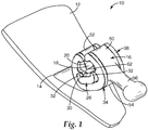
- an orthodontic appliance that is constructed in accordance with one embodiment of the present invention is illustrated in Figs. 1-4 and is broadly designated by the numeral 10.
- the appliance 10 is an orthodontic bracket that is adapted to be secured to a lingual surface of a patient's non-molar tooth.
- the appliance could be a lingual molar appliance, a facial (labial) molar appliance, a facial non-molar appliance or any other orthodontic appliance that is adapted to receive an archwire for controlling movement of the associated tooth during the course of orthodontic treatment.
- the appliance 10 includes a base for bonding the appliance 10 directly to the patient's tooth enamel by the use of an adhesive.
- the base 12 has an outer, tooth-facing surface with a compound contour that matches the compound contour of the patient's tooth surface.
- the compound contour of the outer tooth-facing surface is custom-made to precisely mate with the enamel surface of the patient's tooth in close-fitting relation.
- the tooth-facing surface of the base 12 may be provided with grooves, particles, recesses, undercuts, a chemical bond enhancement material or any other material or structure or any combination of the foregoing that enhances the resulting bond between the appliance 10 and the patient's tooth enamel.
- the shape of the outer, tooth-facing surface of the base 12 can be derived directly from digital representations of the patient's tooth so as to produce a bonding surface that precisely conforms to the shape of the tooth surface.
- a software algorithm is employed that automatically or semi-automatically calculates an appropriate bracket bonding pad area by analyzing the curvature of the tooth surface and determines a base surface that is large enough to cover substantial curvature features to allow for reliable manual positioning of the appliance 10 onto the tooth surface.
- such an algorithm could for instance start with a pre-defined pad size, wherein the tooth surface covered by that pad size would form a virtual "knoll" having at least one raised portion relative to surrounding tooth anatomy, since a completely flat tooth surface would not lend itself to unique positioning of an appliance.
- the volume of the knoll could be calculated provided that the edges of the base 12 are joined by a continuous surface in any convenient manner. The less curvature the tooth surface presents, the flatter the knoll and the smaller its volume would be. If the volume of the knoll does not exceed a pre-defined value, the volume of the base 12 would automatically be enlarged by a pre-defined value, with the idea that the larger volume would be more likely to include adequate raised tooth features. Again, the volume would be calculated. This loop would be continued until a minimum value for the volume would be achieved for the base 12. Alternative methods of determining the shape of the base 12 are also possible.
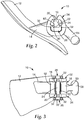
- a neck 14 of the appliance 10 extends outwardly from the base 12, and optionally extends in a direction generally parallel to the occlusal plane of the patient when the appliance is bonded to the patient's tooth.
- a lingual portion of the neck 14 is fixedly connected to a body 16.
- the body 16 has an overall height in an occlusal-gingival direction that is greater than the overall height of the neck 14 in the same direction when viewed in reference planes perpendicular to the direction of extension of the neck 14 away from the base 12.
- the body 16 also has an overall width in a mesial-distal direction that is greater than the mesial-distal width of the neck 14 when considered in the same reference planes.
- the body 16 includes an elongated archwire slot 18 that extends in a generally mesial-distal direction.
- the archwire slot 18 includes two sidewalls 20, 22 that are parallel to each other as well as a bottom wall 24 that extends between the two sidewalls 20, 22 in a generally perpendicular relation.
- the sidewalls 20, 22 and the bottom wall 24 together present a generally "U"-shaped configuration that is adapted to matingly receive an archwire having a generally rectangular cross-sectional configuration.
- the archwire slot 18 is oriented so that an archwire is received in the archwire slots of all appliances located on the dental arch, including the archwire slot 18 of the appliance 10, by moving the archwire toward the arch in a direction perpendicular to the occlusal plane of the patient.
- the bottom wall 24 is preferably parallel to this occlusal plane and the sidewalls 20, 22 are preferably perpendicular to the bottom wall 24. Such orientations facilitate insertion of the archwire into all of the archwire slots simultaneously without undue bending of the archwire.
- the appliance 10 also includes a mesial protrusion 26 that extends outwardly from the body 16 in a generally mesial direction, and a distal protrusion 28 that extends outwardly from the body 16 in a generally distal direction.
- the protrusions 26, 28 each have a flat top surface 30 that is coplanar with the flat bottom wall 24 of the archwire slot 18.
- the protrusions 26, 28 also include generally flat, external lingual and facial wall portions that are each connected by respective curved corner surfaces to a generally flat gingival wall portion.
- Each of the protrusions 26, 28 includes an outer end portion having a pair of tabs 32 that are spaced apart from each other.
- Each tab 32 extends away from the top surface 30 in a generally occlusal direction that is generally parallel to the direction of extension of the sidewalls 20, 22 away from the bottom wall 24 of the archwire slot 18.
- the facing, inner surfaces of the tabs 32 of the protrusions 26, 28 are coplanar with aligned regions of the respective sidewalls 20, 22.
- the appliance 10 additionally includes a latch for releasably retaining an orthodontic archwire in the archwire slot 18.
- the latch comprises a mesial ligating clip 34 and a distal ligating clip 36.
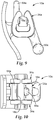
- the mesial clip 34 is shown alone in Fig. 6 in side elevational view.
- the distal clip 36 is identical in construction to the mesial clip 34.
- the mesial clip 34 includes two elongated, curved arm portions 38 that are integrally connected to a bottom portion 40.
- the outer edge of the bottom portion 40 is somewhat flattened.
- Outer ends of the arm portions 38 remote from the bottom portion 40 are inclined in directions toward each other and present an opening 42.
- the clip 34 includes an archwire-receiving region 44 ( Fig. 6 ) adjacent the opening 42 and a recess 48 for receiving the mesial protrusion 26 when the clip 34 is assembled to the body 16 as shown in Figs. 1-4 .
- the clip 34 also includes a pair of prongs 46 that are each connected to a mid-portion of a respective arm portion 38.
- the prongs 46 extend between the archwire-receiving region 44 and the recess 48 and in directions toward each other.
- Each prong 46 also has a small undercut that faces the recess 48.
- the clip 34 is shown in its normal, relaxed orientation in the drawings. However, the arm portions 38 are movable away from each other when desired in order to open the clip 34 and admit an archwire into the archwire-receiving region 44.
- the adjacent, outer end sections of the arm portions 38 are inclined in directions toward each other as the archwire-receiving 44 is approached, which helps to deflect the arm portions 38 away from each other as the archwire is moved into the region 44.
- the prongs 46 slide across the top surface 30 of the mesial protrusion 26 as the clip 34 is opened. However, the prongs 46 extend inwardly and toward each other a distance sufficient to remain in contact with the top surface 30 when the clip 34 is opened to an extent sufficient to receive an archwire. As such, the clip 34 remains coupled to the protrusion 26 during such opening movements and the prongs 46 essentially preclude movement of the clip 34 in a gingival direction, which might otherwise enable the clip 34 to detach from the protrusion 26.
- the inherent resiliency of the clip 34 enables the arm portions 38 to spring back toward each other and toward their normal, relaxed or closed configuration as shown in Figs. 1-4 and 6 in order to retain the archwire in the archwire slot 18.
- the archwire receiving region 44 of the clip 34 is aligned with the archwire slot 18 when the clip 34 is assembled to the body 16.
- the distance between the arm portions 38 in facial-lingual directions and on opposite sides of the archwire receiving region 44 is greater than the distance between the sidewalls 20, 22 of the archwire slot 18, which tends to reduce the resistance to sliding movement between the archwire and the appliance 10 that might otherwise be due to the clip 34.
- the clip 34 (including the arm portions 38) is sufficiently stiff to retain the archwire in the archwire slot 18 during the course of treatment so long as the forces exerted by the archwire on the appliance 10 are below a certain minimum value in a direction opposite to the direction of insertion of the archwire into the archwire slot 18. However, whenever the forces exerted by the archwire on the appliance 10 in that same direction are greater than the minimum value, as might occur when unexpectedly high forces are encountered, the arm portions deflect outwardly and away from each other to open the clip 34 and release the archwire from the archwire slot 18. Further details regarding such forces are described in the aforementioned U.S. Patent Nos. 6,302,688 and 6,582,226 .
- the distal clip 36 is substantially identical to the mesial clip 34 and the distal protrusion 28 is substantially identical in mirror image to the mesial protrusion 26.
- the latch comprising the clips 34, 36, preferably releases the archwire from the archwire slot 18 in a direction generally opposite to the direction of insertion of the archwire in the archwire slot 18 whenever the archwire exerts a force in that same direction on the appliance 10 that is in the range of about 0.1 kg (0.21b) to about 5 kg (111b), more preferably in the range of about 0.2 kg (0.4 lb) to about 2.5 kg (5.5 lb), and most preferably in the range of about 0.34 kg (0.75 lb) to about 1.4 kg (3.0 lb).
- the minimum value is sufficiently high to prevent the archwire from unintentionally releasing from the archwire slot 18 during the normal course of orthodontic treatment.
- the archwire can exert forces on the appliance 10 sufficient to carry out the treatment program and move the associated teeth as desired.
- the minimum value for self-release (i.e., self-opening) of the latch is substantially less than the force required in the same direction to debond the appliance 10 from the associated tooth.
- the minimum value for self-release of the latch is preferably less than about one-half of the force required in the same direction to debond the appliance 10 from the associated tooth. For example, if the expected bond strength of the adhesive bond between the appliance 10 and the associated tooth is 7.2 kg (16 lb) in a direction generally opposite to the direction of insertion of the archwire in the archwire slot 18, the latch is constructed to self-release the archwire whenever the archwire exerts a force in that same direction on the appliance 10 that is somewhat greater than about 3.6 kg (8 lb).
- a section of archwire is selected having an area in longitudinally transverse sections that is complemental to (i.e., substantially fills) the cross-sectional area of the archwire slot 18.
- a sling is constructed and is connected to the archwire section at locations closely adjacent, but not in contact with the outer ends of the protrusions 26, 28.
- the sling is welded or brazed to the archwire section.
- the sling is pulled away from the appliance 10 in a direction opposite of the direction of insertion of the archwire into the archwire slot 18 while the appliance 10 is held in a stationary position, taking care to ensure that the longitudinal axis of the archwire section does not tip relative to the longitudinal axis of the archwire slot 18.
- the force to release the latch may be determined by use of an Instron testing apparatus connected to the sling, using a crosshead speed of 0.5 in/min (1.3 cm/min).
- a shaker apparatus such as Model 300 from APS Dynamics of Carlsbad, Calif.
- a force transducer such as model 208C01 from PCB of Buffalo, N.Y.
- the distance between the opposed ends of the arm portions 38 is less than the overall occlusal-gingival dimension of the smallest archwire expected to be used during the course of treatment.
- the archwire need not fill the archwire slot 18 and flatly engage the wall portions defining the archwire slot 18 in all instances.
- a somewhat smaller wire, and perhaps an archwire having a circular cross-sectional shape may be used during a portion of the treatment program.
- the distance between the outer ends of the arm portions 38 is preferably selected so that a variety of archwires of different cross-sectional configurations may be used in connection with the appliance 10.
- the distal clip 36 is identical to the mesial clip 34.
- the clips 34, 36 it is possible to construct the clips 34, 36 somewhat differently to provide certain treatment procedures for a particular patient. For example, if a malpositioned tooth is initially oriented such that its mesial side should be rotated in a lingual direction in order to improve its position, it may be desirable to increase the stiffness of the mesial clip 34 so that a somewhat greater force is needed to release the archwire from the archwire slot 18 in comparison to the force needed to release the archwire from the distal clip 36. Other options are also possible.
- the spring clips 34, 36 are cut from a flat section of metallic stock material.
- Suitable metallic materials include shape memory alloys such as alloys of nitinol and beta-titanium.
- the clips 34, 36 may be cut from the stock material using a stamping, die cutting, chemical etching, EDM (electrical discharge machining), laser cutting or water jet cutting process.
- the clips 34, 36 could be formed and then heat-treated to set their shapes.
- the clips 34, 36 are made from flat annealed superelastic material (such as nitinol) having a pickled surface.
- Preferred nitinol materials have a nickel content of 55.97% by weight and an A f of 10° ⁇ 5° C.
- the nitinol is cold worked to 37.5% and has a thickness in the range of about 0.012 in. (0.3 mm) to about 0.016 in. (0.4 mm).
- the clips 34, 36 are first cut in a rough cutting EDM process, then cut along their edges for an additional one or more times using an EDM process in order to smooth the edges.
- a laser cutting process or chemical etching process could be used to make the clips 34, 36.
- the clips 34, 36 are constructed so that the longitudinal direction of the clip material, or the principal direction of grain flow of the clip material, is substantially parallel to the direction of extension of the arm portions 38 (i.e. in a generally occlusal direction in the illustrated embodiment).
- the clips 34, 36 are tumbled in order to further round their edges.
- An example of a suitable tumbling machine is model LC-600-2+2 from Richwood Industries of Hawthorne, California. Using a small barrel, and a machine speed of 200 rpm, the clips are tumbled for about 2 hours in 500 cc of water and tumbling media.
- An example of suitable tumbling media is a mixture of 500 cc of ceramic media (shaped ACC, type M, size 3/16 ⁇ 3 ⁇ 8 (4.7 mm ⁇ 9.5 mm)), 25 cc of white alumina powder no. 40, and 25 cc of soap powder compound no. 43, all from Richwood Industries.
- the tumbled clips are then polished for one-half hour in an ultrasonic screen barrel in a tank of solution.
- An example of a suitable solution is 3 liters of deionized water, 3 liters of pickling solution and 0.6 liter of hydrogen peroxide.
- a suitable pickling solution is No. TI121 Pickling Solution from Aya International of Los Angeles, Calif.
- the latch comprising the clips 34, 36
- the archwire slot 18 together form an assembly that has a certain orientation relative to the base 12. This orientation is customized to the configuration of the specific tooth of the specific patient.
- the clips 34, 36 and the archwire slot 18 have openings that are aligned with each other, and the orientation of the openings is custom-oriented to the orientation of the base 12.
- the orientation of the assembly may vary from patient to patient in accordance with the specific configuration of the patient's cuspid tooth and/or of other aspects of the dental structure for the specific patient undergoing treatment.
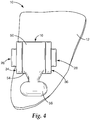
- the body 16 includes a curved lingual wall section 50 and a curved facial wall section 52.
- the body 16 also includes a gingival wall section 54 that interconnects the wall sections 50, 52.
- the gingival wall section 54 presents a somewhat flattened configuration.
- the wall sections 50, 52, 54 of the body 16 present a generally oval-shaped external profile that matches the generally oval-shaped external profile of the clips 34, 36.
- These oval-shaped profiles have a short axis and a long axis, and preferably the long axis is oriented in a direction that is perpendicular to the occlusal plane of the patient when the appliance 10 is bonded to the lingual side of the patient's tooth.
- the oval-shape external profile of the clips 34, 36 is aligned with the generally oval-shaped external profile of the body 16 with the result that a smoothly curved, compact assembly is presented.
- the matching, smoothly curved oval-shaped external profiles of the clips 34, 36 and the body 16 is highly beneficial in providing patient comfort, a particular advantage for appliances that are bonded to the lingual surfaces of a patient's teeth.
- the openings of the clips 34, 36 are aligned with the opening of the body 16 that leads into the archwire slot 18.
- the appliance 10 includes a double ended or "T"-shaped hook 56 that extends outwardly from the lingual wall section 50 of the body 16.
- Other types of hooks are also possible, such as hooks with a generally “L"-shaped configuration, or hooks with ball-shaped heads.
- the appliance 10 may include a pair of spaced-apart "L"-shaped hooks with outer ends that extend in directions away from each other. The use of a pair of hooks is especially advantageous for appliances that have a relatively large width in a mesial-distal direction, such as appliances constructed for use on the patient's molar teeth.
- the appliance 10 may also include tiewings in place of a hook or hooks or in addition to a hook or hooks.
- One method of making the appliance 10 includes the step of making an appliance preform such as the preform 58 illustrated in Fig. 7 .
- the preform 58 initially includes a runner 60 which is detached when the archwire slot 18 is cut.
- certain features of the preform 58 as depicted in Fig. 7 are similar to features of the resulting appliance 10 shown in Figs. 1-4 , the preform 58 lacks the archwire slot 18.
- the protrusions 26, 28 of the resulting appliance 10 have a different configuration than the corresponding regions of the preform 58 shown in Fig. 7 .
- a system for forming the archwire slot 18 may include an electrical discharge machining apparatus that includes a controller having memory which can provide for computer numerical control.
- the electrical discharge machining apparatus can include a traveling wire electrical discharge electrode, or a traveling wire electrode and a die-sinker electrical discharge electrode.
- the electrical discharge machining apparatus can include at least one drive section adapted to position the appliance 10 in electrical discharge contact with the electrode to form the archwire slot 18 and to simultaneously separate the body 16 from the runner 60 when forming the archwire slot 18 responsive to the control signal.
- the cutting tool (such as the electrical discharge machining apparatus) is advanced into the preform 58, the cutting tool also cuts a top portion of the protrusions 26, 28 to thereby form the top surfaces 30.
- the bottom wall 24 of the archwire slot 18 is formed simultaneously with forming of the top surfaces 30.
- the preform 58 can be mounted on a drive table that is activated for movement by a control signal to enable a traveling wire electrode of an electrical discharge machining apparatus to simultaneously cut the bottom wall 24 and both of the top surfaces 30.
- Such a methodology helps ensure that the top surfaces 30 of the protrusions 26, 28 are each precisely coplanar with the bottom wall 24 of the archwire slot 18. This coplanar relationship is an advantage, in that the extended top surfaces 30 provide enhanced tipping control over movement of the associated tooth.
- an undercut 62 (see Fig. 1 ) is formed at the bottom of each sidewall 20, 22 of the archwire slot at a location next to the bottom wall 24.
- the tabs 32 include facing wall surfaces with a configuration matching a portion of the undercuts 62 and aligned with the undercuts 62, as may occur when a traveling wire electrode as described above is used to form the archwire slot 18.
- FIG. 8-10 An orthodontic appliance 10a according to other embodiment of the invention is illustrated in Figs. 8-10 . Except as noted below, the appliance 10a is essentially the same as the appliance 10 and consequently a detailed description of the similar aspects will not be repeated.
- the appliance 10a includes a body 16a with an archwire slot 18a that extends in a generally mesial-distal direction.
- a "T"-shaped hook 56a is integrally connected to the body 16a.
- the hook 56a extends in a generally gingival direction and is similar to the hook 56 described above.
- the appliance 10a also includes a hook 64a that extends in a generally occlusal direction.
- the hook 64a generally resembles a flat bar and is connected to the body 16a at a central location along the tooth-facing side of the archwire slot 18a.
- the body 16a includes a notch 66a that is adjacent to the opening to the archwire slot 18a and opposite the hook 64a.
- the notch 66a is adapted to receive a protrusion of a hand instrument that is constructed to remove an archwire from the archwire slot 18a.
- the notch 66a provides structure to facilitate steady and properly aligned contact of the hand instrument with the appliance 10a during a procedure to release the archwire from the appliance clips and remove the archwire from the archwire slot 18a.
- An example of a suitable hand instrument for removing the archwire is described in applicant's copending U.S. Patent Application Serial No. 61/084,688 entitled "Hand Instrument for Removing an Orthodontic Archwire from an Orthodontic Appliance".
- the appliance 10a also includes a pair of clips 34a, 36a that are coupled to the body 16a.
- the clips 34a, 36a have a generally "teardrop" external profile that matches a generally teardrop external profile of the body 16a.
- the teardrop external profile of the appliance 10a presents a smoothly-curved external profile that is highly beneficial in provide patient comfort.
Landscapes
- Health & Medical Sciences (AREA)
- Oral & Maxillofacial Surgery (AREA)
- Dentistry (AREA)
- Epidemiology (AREA)
- Life Sciences & Earth Sciences (AREA)
- Animal Behavior & Ethology (AREA)
- General Health & Medical Sciences (AREA)
- Public Health (AREA)
- Veterinary Medicine (AREA)
- Dental Tools And Instruments Or Auxiliary Dental Instruments (AREA)
Claims (11)
- Appareil orthodontique autoligaturant comportant :une base (12) possédant une surface externe pour se lier à une dent, la surface externe ayant un contour composé qui correspond au contour composé de la surface dentaire du patient ;un corps (16) relié intégralement à la base (12), le corps (16) comprenant une encoche d'arc dentaire allongée (18) s'étendant dans une direction distale généralement mésiale, dans lequel l'encoche d'arc dentaire (18) comprend une ouverture ; etun verrou comprenant une attache mésiale (34) et une attache distale (36) couplées au corps (16) pour retenir de manière libérable un arc dentaire dans l'encoche d'arc dentaire (18), dans lequel l'attache mésiale (34) et l'attache distale (36) ont chacune une ouverture qui est alignée avec l'ouverture de l'encoche d'arc dentaire (18), le verrou et le corps (16) comprenant des composants distincts initialement séparés,dans lequel l'encoche d'arc dentaire (18) et le verrou forment conjointement un ensemble ; etdans lequel l'ensemble a une certaine orientation par rapport à la base (12) qui est personnalisée à une configuration d'une dent spécifique d'un patient spécifique.
- Appareil orthodontique autoligaturant selon la revendication 1, dans lequel la base (12) a une configuration correspondant à la configuration d'une dent spécifique d'un patient spécifique.
- Appareil orthodontique autoligaturant selon la revendication 1, et comprenant en outre un col (14) s'étendant vers l'extérieur à partir de la base (12), dans lequel le corps (16) est relié à une partie linguale du col (14).
- Appareil orthodontique autoligaturant selon la revendication 1, dans lequel le corps (16) et chaque attache (34 ; 36) présentent des profils externes de forme généralement ovale ou de forme généralement de goutte correspondants.
- Appareil orthodontique autoligaturant selon la revendication 4, dans lequel les profils externes de forme ovale ont un axe court et un axe long, et dans lequel l'axe long est orienté dans une direction perpendiculaire à un plan d'occlusion.
- Appareil orthodontique autoligaturant selon la revendication 5, dans lequel le profil de forme ovale présenté par le corps (16) et le profil de forme ovale présenté par les attaches (34 ; 36) comprennent des ouvertures alignées pour admettre un arc dentaire dans l'encoche d'arc dentaire (18).
- Appareil orthodontique autoligaturant selon la revendication 6, dans lequel les profils externes de forme généralement ovale présentés par le corps (16) et les attaches (34 ; 36) comprennent un axe court et un axe long, dans lequel l'axe long est orienté dans une direction généralement perpendiculaire à un plan d'occlusion, et dans lequel les ouvertures alignées sont situées le long de l'axe long.
- Appareil orthodontique autoligaturant selon la revendication 1, dans lequel la surface externe de la base (12) a une configuration correspondant à la configuration de la surface de dent linguale.
- Appareil orthodontique autoligaturant selon la revendication 1, dans lequel le col (14) s'étend le long d'un plan de référence généralement parallèle au plan d'occlusion.
- Procédé de fabrication d'une orthèse orthodontique comprenant :pour chaque dent devant recevoir un appareil, définir une base d'appareil ayant une configuration qui correspond à la configuration d'une dent spécifique d'un patient spécifique ;pour chaque appareil, former la base d'appareil (12) conjointement avec un corps d'appareil (16) en tant que composant intégral, le corps (16) comprenant une encoche d'arc dentaire (18) ayant une certaine orientation par rapport à la base (12) qui est sélectionnée en fonction de la configuration de dent spécifique du patient spécifique ; etpour chaque appareil, connecter un verrou comprenant une attache mésiale (34) et une attache distale (36) au corps pour retenir de manière libérable un arc dentaire dans l'encoche d'arc dentaire (18), dans lequel le fait de relier le verrou au corps (16) comprend le fait de positionner le verrou selon une certaine orientation par rapport à l'encoche d'arc dentaire (18), et dans lequel la certaine orientation est constante pour chaque appareil de l'orthèse.
- Procédé selon la revendication 10, dans lequel l'encoche d'arc dentaire (18) de chaque appareil comprend une ouverture, et dans lequel l'attache mésiale (34) et l'attache distale (36) ont chacune une ouverture qui est alignée avec l'ouverture de l'encoche d'arc dentaire (18) de l'appareil correspondant.
Applications Claiming Priority (2)
| Application Number | Priority Date | Filing Date | Title |
|---|---|---|---|
| US8469108P | 2008-07-30 | 2008-07-30 | |
| PCT/US2009/051790 WO2010014518A2 (fr) | 2008-07-30 | 2009-07-27 | Appareil orthodontique auto-ligaturant et à profil bas avec attache |
Publications (2)
| Publication Number | Publication Date |
|---|---|
| EP2328506A2 EP2328506A2 (fr) | 2011-06-08 |
| EP2328506B1 true EP2328506B1 (fr) | 2018-11-28 |
Family
ID=41258995
Family Applications (1)
| Application Number | Title | Priority Date | Filing Date |
|---|---|---|---|
| EP09790832.1A Not-in-force EP2328506B1 (fr) | 2008-07-30 | 2009-07-27 | Appareil orthodontique auto-ligaturant et à profil bas avec attache |
Country Status (4)
| Country | Link |
|---|---|
| US (2) | US9585734B2 (fr) |
| EP (1) | EP2328506B1 (fr) |
| JP (1) | JP5525526B2 (fr) |
| WO (1) | WO2010014518A2 (fr) |
Families Citing this family (21)
| Publication number | Priority date | Publication date | Assignee | Title |
|---|---|---|---|---|
| US8827698B2 (en) * | 2009-12-02 | 2014-09-09 | 3M Innovative Properties Company | Orthodontic appliance with low profile clip |
| KR102071869B1 (ko) | 2010-12-08 | 2020-01-31 | 스트라이트 인더스트리즈 리미티드 | 치과교정용 그리핑 장치 |
| KR101405771B1 (ko) | 2012-05-25 | 2014-06-10 | 이화여자대학교 산학협력단 | 교정 브라켓 및 그를 구비한 치아 교정기 |
| WO2014070920A1 (fr) | 2012-10-30 | 2014-05-08 | University Of Southern California | Appareil orthodontique pourvu d'un fil métallique non-coulissant pour arc dentaire à encliqueter |
| WO2014137654A1 (fr) * | 2013-03-08 | 2014-09-12 | Overjet Llc | Bracket orthodontique autoligaturant statique et procédé d'utilisation de celui-ci |
| US10419428B2 (en) | 2015-07-05 | 2019-09-17 | NXT-ID, Inc. | System and method to authenticate electronics using electronic-metrics |
| US10085824B2 (en) | 2015-10-30 | 2018-10-02 | Ortho Organizers, Inc. | Self ligating orthodontic bracket |
| JP6899393B2 (ja) * | 2016-01-29 | 2021-07-07 | スリーエム イノベイティブ プロパティズ カンパニー | 歯科矯正用ブラケット及び歯科矯正用ブラケット製造方法 |
| ES2645250B1 (es) * | 2016-06-03 | 2018-09-24 | Carlos Manuel MORALES RICO | Dispositivo de conexión entre un aparato odontológico y su anclaje |
| CN110177521A (zh) | 2016-12-02 | 2019-08-27 | 斯威夫特健康系统有限公司 | 用于托槽放置的间接正畸粘结系统和方法 |
| WO2018144634A1 (fr) | 2017-01-31 | 2018-08-09 | Swift Health Systems Inc. | Arcs orthodontiques hybrides |
| US11612458B1 (en) | 2017-03-31 | 2023-03-28 | Swift Health Systems Inc. | Method of tongue preconditioning in preparation for lingual orthodontic treatment |
| EP4282376A3 (fr) | 2017-04-21 | 2024-01-24 | Swift Health Systems Inc. | Plateau de liaison indirecte ayant plusieurs poignets |
| EP3461453A1 (fr) * | 2017-09-28 | 2019-04-03 | 3M Innovative Properties Company | Support orthodontique et appareil orthodontique |
| CN113710191A (zh) | 2019-03-01 | 2021-11-26 | 斯威夫特健康系统有限公司 | 具有咬合附件和正畸辅助物集成的间接粘接托盘 |
| AU2020264490A1 (en) * | 2019-05-02 | 2021-11-25 | World Class Technology Corporation | Orthodontic bracket with a biased ligating member |
| CN114727853B (zh) | 2019-10-31 | 2024-10-01 | 斯威夫特健康系统有限公司 | 间接正畸粘合系统和方法 |
| KR20230051157A (ko) | 2020-06-11 | 2023-04-17 | 스위프트 헬스 시스템즈 인코포레이티드 | 논슬라이딩 아치 구조를 구비한 교정 장치 |
| EP4395688A1 (fr) | 2021-09-03 | 2024-07-10 | Swift Health Systems Inc. | Procédé d'administration d'adhésif pour collage de verrous orthodontiques |
| EP4151176A1 (fr) * | 2021-09-16 | 2023-03-22 | Ormco Corporation | Crochets d'arc dentaire, butées et procédés d'utilisation associés |
| USD1043994S1 (en) | 2022-01-06 | 2024-09-24 | Swift Health Systems Inc. | Archwire |
Family Cites Families (75)
| Publication number | Priority date | Publication date | Assignee | Title |
|---|---|---|---|---|
| US1991047A (en) | 1933-01-17 | 1935-02-12 | Boyd Charles Edward | Orthodontia band bracket |
| US2368851A (en) | 1943-04-24 | 1945-02-06 | Jacob E Laskin | Orthodontic bracket |
| US3052027A (en) | 1960-01-20 | 1962-09-04 | Wallshein Melvin | Orthodontic appliances |
| US3084437A (en) | 1960-04-07 | 1963-04-09 | Neger Milton | Orthodontic appliance |
| US3327393A (en) | 1964-06-16 | 1967-06-27 | Allen C Brader | Orthodontic arch wire edgewise brackets |
| US3464113A (en) | 1966-08-03 | 1969-09-02 | Elliott Silverman | Orthodontic appliance |
| US3464112A (en) * | 1967-06-30 | 1969-09-02 | Elliott Silverman | Orthodontic appliance |
| US3724074A (en) | 1971-02-22 | 1973-04-03 | M Wallshein | Brackets for supporting arch wires, and adapted to function in orthodontic procedures in systems for tilting, uprighting and turning teeth |
| US3772787A (en) | 1972-03-17 | 1973-11-20 | G Hanson | Orthodontic bracket |
| US4023274A (en) * | 1975-06-02 | 1977-05-17 | Melvin Wallshein | Orthodontic spring clip |
| CH619611A5 (fr) | 1977-01-17 | 1980-10-15 | Foerster Bernhard Fa | |
| US4149314A (en) | 1977-02-18 | 1979-04-17 | Nonnenmann Michael J | Orthodontic brackets with pivotal fastenings |
| US4103423A (en) | 1977-03-04 | 1978-08-01 | Kessel Stanley P | Orthodontic bracket |
| US4197642A (en) | 1977-09-29 | 1980-04-15 | Melvin Wallshein | Bent wire orthodontic spring clip |
| US4248588A (en) | 1979-04-27 | 1981-02-03 | Hanson Gustaf H | Orthodontic bracket and arch wire |
| US4260375A (en) | 1979-12-13 | 1981-04-07 | Melvin Wallshein | Bent wire orthodontic spring clip |
| US4371337A (en) | 1981-05-20 | 1983-02-01 | Pletcher Erwin Carroll | Orthodontic bracket |
| JPS5850951A (ja) | 1981-09-22 | 1983-03-25 | セイコーエプソン株式会社 | 歯列矯正用ブラケツト |
| US4496318A (en) | 1982-05-17 | 1985-01-29 | Connelly Jr Harold R | Converters for orthodontic treatment |
| JPS5916612A (ja) | 1982-07-20 | 1984-01-27 | Nippon Kokan Kk <Nkk> | H形鋼のウエブ偏り制御方法 |
| US4531911A (en) | 1983-12-05 | 1985-07-30 | Creekmore Thomas D | Combination single/twin edgewise orthodontic bracket |
| US4492573A (en) | 1984-03-27 | 1985-01-08 | Augusta Developments Inc. | Orthodontic bracket |
| US4559012A (en) | 1984-12-06 | 1985-12-17 | Pletcher Erwin Carroll | Orthodontic bracket |
| US4551094A (en) | 1985-01-31 | 1985-11-05 | Kesling Peter C | Edgewise bracket wire retaining clip |
| US4725229A (en) | 1986-06-18 | 1988-02-16 | Ormco Corporation | Orthodontic bracket |
| US4712999A (en) | 1986-09-10 | 1987-12-15 | Farel Rosenberg | Convertible, self-ligating, archwire positioning orthodontic bracket |
| US4698017A (en) | 1986-12-10 | 1987-10-06 | Hanson Gustaf H | Orthodontic brackets |
| JPH01165015A (ja) | 1987-12-21 | 1989-06-29 | Alps Electric Co Ltd | 回転ヘッド装置の軸受機構 |
| US4846681A (en) | 1988-03-07 | 1989-07-11 | Mourany Haitham E | Orthodontic bracket |
| US5474444A (en) | 1988-09-26 | 1995-12-12 | Wildman; Alexander J. | Multiwire arch system |
| US5039302A (en) | 1990-02-01 | 1991-08-13 | Johnson & Johnson Consumer Products, Inc. | Dental bracket instrument |
| US5094614A (en) | 1991-03-08 | 1992-03-10 | Wildman Alexander J | Miniature self-locking labial bracket |
| US5174754A (en) * | 1991-11-13 | 1992-12-29 | Johnson & Johnson Consumer Products, Inc. | Self-ligating, self-locking dental bracket with T-shaped archwire slot |
| US5269681A (en) | 1992-05-15 | 1993-12-14 | Degnan Edward V | Integrated ligature and orthodontic bracket |
| JP3214063B2 (ja) | 1992-05-19 | 2001-10-02 | 富士写真光機株式会社 | ホログラム干渉計装置 |
| US5322435A (en) | 1992-07-23 | 1994-06-21 | Pletcher Erwin Carroll | Orthodontic bracket |
| JPH0626814U (ja) | 1992-09-01 | 1994-04-12 | 和也 渡辺 | 矯正歯科用ブラケット |
| US5630715A (en) | 1993-01-21 | 1997-05-20 | Voudouris; John C. | Orthodontic bracket with an engagement mechanism for retaining an archwire |
| US5466151A (en) | 1993-04-08 | 1995-11-14 | Damon Family Limited Partnership | Spring-locked orthodontic bracket |
| US5380196A (en) | 1993-05-13 | 1995-01-10 | Minnesota Mining And Manufacturing Company | Orthodontic bracket with archwire slot liner |
| US5358402A (en) | 1993-05-13 | 1994-10-25 | Minnesota Mining & Manufacturing Company | Ceramic orthodontic bracket with archwire slot liner |
| US5439379A (en) | 1993-11-29 | 1995-08-08 | Minnesota Mining And Manufacturing Company | Ceramic orthodontic bracket with debonding channel |
| US5366372A (en) | 1993-11-29 | 1994-11-22 | Minnesota Mining And Manufacturing Company | Method and apparatus for debonding ceramic orthodontic brackets |
| DE4407100C2 (de) | 1994-03-03 | 1997-11-13 | Wolfgang Dr Med Heiser | Bracket für kieferorthopädische Behandlungen |
| US5474445A (en) | 1994-03-07 | 1995-12-12 | John Voudouris | Self-engaging twin edge-wise orthodontic bracket with pivotal latch |
| US5913680A (en) | 1994-03-07 | 1999-06-22 | Voudouris; John C. | Orthodontic bracket |
| US5857850A (en) | 1994-03-07 | 1999-01-12 | Voudouris; John C. | Orthodontic appliance |
| US5908293A (en) | 1994-03-07 | 1999-06-01 | Voudouris; John C. | Orthodontic bracket |
| US5474446A (en) | 1994-07-06 | 1995-12-12 | Wildman; Alexander J. | Miniature self-locking labial bracket with cam-release closure member |
| US5700145A (en) | 1995-06-05 | 1997-12-23 | Wildman; Alexander J. | Lingual bracket with hinged camming closure and releasable lock |
| US5685711A (en) | 1995-12-06 | 1997-11-11 | Hanson; G. Herbert | Self-ligating orthodontic brackets |
| US5630716A (en) | 1995-12-29 | 1997-05-20 | Hanson; G. Herbert | Self-ligating orthodontic brackets |
| US5711666A (en) | 1996-10-22 | 1998-01-27 | Hanson; G. Herbert | Self-ligating orthodontic brackets |
| US5857849A (en) | 1996-12-06 | 1999-01-12 | Kurz; Craven | Self-ligating low profile orthodontic bracket |
| US6168428B1 (en) | 1997-11-12 | 2001-01-02 | John C. Voudouris | Orthodontic bracket |
| US5890893A (en) | 1998-02-26 | 1999-04-06 | Heiser; Wolfgang | Orthodontic bracket |
| US5967773A (en) | 1998-12-22 | 1999-10-19 | Orthodontic Design & Production | Orthodontic bracket with spring cover |
| US6071119A (en) | 1998-12-22 | 2000-06-06 | 3M Innovative Properties Company | Dual mode self-ligating orthodontic bracket |
| US6193508B1 (en) | 1999-03-25 | 2001-02-27 | 3M Innovative Properties Company | Self-ligating orthodontic bracket with enhanced rotation control |
| US6582226B2 (en) | 1999-09-27 | 2003-06-24 | 3M Innovative Properties Company | Orthodontic appliance with self-releasing latch |
| US6302688B1 (en) | 1999-09-27 | 2001-10-16 | 3M Innovative Properties Company | Orthodontic appliance with self-releasing latch |
| EP1234549A1 (fr) | 2001-02-14 | 2002-08-28 | Heiser, Wolfgang, Dr. med. | Verrou lingual |
| US6554612B2 (en) * | 2001-06-25 | 2003-04-29 | 3M Innovative Properties Company | Orthodontic bracket with recessed attachment and method for making the same |
| US6733285B2 (en) * | 2001-12-14 | 2004-05-11 | 3M Innovative Properties Company | Orthodontic appliance with lingual retaining groove |
| US6663385B2 (en) * | 2001-12-20 | 2003-12-16 | Harry W. Tepper | Orthodontic snap-in bracket |
| US6776614B2 (en) * | 2002-02-13 | 2004-08-17 | Lingualcare, Inc. | Modular system for customized orthodontic appliances |
| US6957957B2 (en) * | 2002-11-04 | 2005-10-25 | 3M Innovative Properties Company | Molar appliance for orthodontic therapy |
| US7140876B2 (en) * | 2003-10-31 | 2006-11-28 | 3M Innovative Properties Company | Orthodontic appliance with latch for retaining an archwire |
| WO2005044131A1 (fr) * | 2003-11-07 | 2005-05-19 | Innobrace Orthodontics Pte. Ltd. | Appareil orthodontique |
| US7252505B2 (en) * | 2004-07-28 | 2007-08-07 | 3M Innovative Properties Company | Self-ligating orthodontic appliance with post for connection to a latch |
| US20060024634A1 (en) | 2004-07-28 | 2006-02-02 | 3M Innovative Properties Company | Self-ligating orthodontic appliance with clip |
| US7377777B2 (en) | 2005-12-23 | 2008-05-27 | 3M Innovative Properties Company | Orthodontic appliance with archwire-engaging clip |
| US7751925B2 (en) | 2006-01-27 | 2010-07-06 | 3M Innovative Properties Company | System to manufacture custom orthodontic appliances, program product, and related methods |
| DE102006025845B3 (de) | 2006-06-02 | 2008-01-24 | T.O.P. Service für Lingualtechnik GmbH | Bracket mit einem Pad |
| WO2010014299A1 (fr) | 2008-07-30 | 2010-02-04 | 3M Innovative Properties Company | Instrument à main pour retirer un fil métallique pour arc orthodontique à partir d'un appareil orthodontique |
-
2009
- 2009-07-27 EP EP09790832.1A patent/EP2328506B1/fr not_active Not-in-force
- 2009-07-27 WO PCT/US2009/051790 patent/WO2010014518A2/fr active Application Filing
- 2009-07-27 US US13/056,171 patent/US9585734B2/en not_active Expired - Fee Related
- 2009-07-27 JP JP2011521212A patent/JP5525526B2/ja active Active
-
2017
- 2017-01-26 US US15/415,946 patent/US20170128169A1/en not_active Abandoned
Non-Patent Citations (1)
| Title |
|---|
| None * |
Also Published As
| Publication number | Publication date |
|---|---|
| JP2011529727A (ja) | 2011-12-15 |
| US20140065566A1 (en) | 2014-03-06 |
| US20170128169A1 (en) | 2017-05-11 |
| US9585734B2 (en) | 2017-03-07 |
| JP5525526B2 (ja) | 2014-06-18 |
| WO2010014518A3 (fr) | 2010-08-19 |
| EP2328506A2 (fr) | 2011-06-08 |
| WO2010014518A2 (fr) | 2010-02-04 |
Similar Documents
| Publication | Publication Date | Title |
|---|---|---|
| EP2328506B1 (fr) | Appareil orthodontique auto-ligaturant et à profil bas avec attache | |
| EP1558167B1 (fr) | Appareil orthodontique avec verrou de retenue d'arc resistant a la fatigue | |
| EP1796574B1 (fr) | Appareil orthodontique a auto-ligaturage avec attache | |
| EP1843716B1 (fr) | Appareil orthodontique a application prealable de couple dote d'un dispositif de verrouillage retenant un arc dentaire | |
| EP1778122B1 (fr) | Appareil orthodontique d'auto-ligaturage avec montant de raccord a un taquet | |
| EP1962714B1 (fr) | Appareilage orthodontique avec clip entrant en prise avec un arc | |
| EP1558168B1 (fr) | Appareil molaire de traitement orthodontique | |
| US20230072074A1 (en) | Orthodontic appliance with non-sliding archform | |
| JP4406004B2 (ja) | 自己解放式器具を備えた歯列矯正ブレース | |
| US8827698B2 (en) | Orthodontic appliance with low profile clip | |
| US7140876B2 (en) | Orthodontic appliance with latch for retaining an archwire | |
| EP2142134B1 (fr) | Bracket orthodontique en céramique avec caractéristiques de détachement perfectionnées |
Legal Events
| Date | Code | Title | Description |
|---|---|---|---|
| PUAI | Public reference made under article 153(3) epc to a published international application that has entered the european phase |
Free format text: ORIGINAL CODE: 0009012 |
|
| 17P | Request for examination filed |
Effective date: 20110225 |
|
| AK | Designated contracting states |
Kind code of ref document: A2 Designated state(s): AT BE BG CH CY CZ DE DK EE ES FI FR GB GR HR HU IE IS IT LI LT LU LV MC MK MT NL NO PL PT RO SE SI SK SM TR |
|
| AX | Request for extension of the european patent |
Extension state: AL BA RS |
|
| DAX | Request for extension of the european patent (deleted) | ||
| 17Q | First examination report despatched |
Effective date: 20150413 |
|
| STAA | Information on the status of an ep patent application or granted ep patent |
Free format text: STATUS: EXAMINATION IS IN PROGRESS |
|
| GRAP | Despatch of communication of intention to grant a patent |
Free format text: ORIGINAL CODE: EPIDOSNIGR1 |
|
| STAA | Information on the status of an ep patent application or granted ep patent |
Free format text: STATUS: GRANT OF PATENT IS INTENDED |
|
| INTG | Intention to grant announced |
Effective date: 20180629 |
|
| GRAS | Grant fee paid |
Free format text: ORIGINAL CODE: EPIDOSNIGR3 |
|
| GRAA | (expected) grant |
Free format text: ORIGINAL CODE: 0009210 |
|
| STAA | Information on the status of an ep patent application or granted ep patent |
Free format text: STATUS: THE PATENT HAS BEEN GRANTED |
|
| AK | Designated contracting states |
Kind code of ref document: B1 Designated state(s): AT BE BG CH CY CZ DE DK EE ES FI FR GB GR HR HU IE IS IT LI LT LU LV MC MK MT NL NO PL PT RO SE SI SK SM TR |
|
| REG | Reference to a national code |
Ref country code: GB Ref legal event code: FG4D |
|
| REG | Reference to a national code |
Ref country code: CH Ref legal event code: EP |
|
| REG | Reference to a national code |
Ref country code: AT Ref legal event code: REF Ref document number: 1069331 Country of ref document: AT Kind code of ref document: T Effective date: 20181215 |
|
| REG | Reference to a national code |
Ref country code: DE Ref legal event code: R096 Ref document number: 602009055942 Country of ref document: DE |
|
| REG | Reference to a national code |
Ref country code: IE Ref legal event code: FG4D |
|
| REG | Reference to a national code |
Ref country code: NL Ref legal event code: MP Effective date: 20181128 |
|
| REG | Reference to a national code |
Ref country code: LT Ref legal event code: MG4D |
|
| REG | Reference to a national code |
Ref country code: AT Ref legal event code: MK05 Ref document number: 1069331 Country of ref document: AT Kind code of ref document: T Effective date: 20181128 |
|
| PG25 | Lapsed in a contracting state [announced via postgrant information from national office to epo] |
Ref country code: IS Free format text: LAPSE BECAUSE OF FAILURE TO SUBMIT A TRANSLATION OF THE DESCRIPTION OR TO PAY THE FEE WITHIN THE PRESCRIBED TIME-LIMIT Effective date: 20190328 Ref country code: FI Free format text: LAPSE BECAUSE OF FAILURE TO SUBMIT A TRANSLATION OF THE DESCRIPTION OR TO PAY THE FEE WITHIN THE PRESCRIBED TIME-LIMIT Effective date: 20181128 Ref country code: AT Free format text: LAPSE BECAUSE OF FAILURE TO SUBMIT A TRANSLATION OF THE DESCRIPTION OR TO PAY THE FEE WITHIN THE PRESCRIBED TIME-LIMIT Effective date: 20181128 Ref country code: LT Free format text: LAPSE BECAUSE OF FAILURE TO SUBMIT A TRANSLATION OF THE DESCRIPTION OR TO PAY THE FEE WITHIN THE PRESCRIBED TIME-LIMIT Effective date: 20181128 Ref country code: NO Free format text: LAPSE BECAUSE OF FAILURE TO SUBMIT A TRANSLATION OF THE DESCRIPTION OR TO PAY THE FEE WITHIN THE PRESCRIBED TIME-LIMIT Effective date: 20190228 Ref country code: LV Free format text: LAPSE BECAUSE OF FAILURE TO SUBMIT A TRANSLATION OF THE DESCRIPTION OR TO PAY THE FEE WITHIN THE PRESCRIBED TIME-LIMIT Effective date: 20181128 Ref country code: ES Free format text: LAPSE BECAUSE OF FAILURE TO SUBMIT A TRANSLATION OF THE DESCRIPTION OR TO PAY THE FEE WITHIN THE PRESCRIBED TIME-LIMIT Effective date: 20181128 Ref country code: BG Free format text: LAPSE BECAUSE OF FAILURE TO SUBMIT A TRANSLATION OF THE DESCRIPTION OR TO PAY THE FEE WITHIN THE PRESCRIBED TIME-LIMIT Effective date: 20190228 Ref country code: HR Free format text: LAPSE BECAUSE OF FAILURE TO SUBMIT A TRANSLATION OF THE DESCRIPTION OR TO PAY THE FEE WITHIN THE PRESCRIBED TIME-LIMIT Effective date: 20181128 |
|
| PG25 | Lapsed in a contracting state [announced via postgrant information from national office to epo] |
Ref country code: SE Free format text: LAPSE BECAUSE OF FAILURE TO SUBMIT A TRANSLATION OF THE DESCRIPTION OR TO PAY THE FEE WITHIN THE PRESCRIBED TIME-LIMIT Effective date: 20181128 Ref country code: PT Free format text: LAPSE BECAUSE OF FAILURE TO SUBMIT A TRANSLATION OF THE DESCRIPTION OR TO PAY THE FEE WITHIN THE PRESCRIBED TIME-LIMIT Effective date: 20190328 Ref country code: GR Free format text: LAPSE BECAUSE OF FAILURE TO SUBMIT A TRANSLATION OF THE DESCRIPTION OR TO PAY THE FEE WITHIN THE PRESCRIBED TIME-LIMIT Effective date: 20190301 |
|
| PG25 | Lapsed in a contracting state [announced via postgrant information from national office to epo] |
Ref country code: NL Free format text: LAPSE BECAUSE OF FAILURE TO SUBMIT A TRANSLATION OF THE DESCRIPTION OR TO PAY THE FEE WITHIN THE PRESCRIBED TIME-LIMIT Effective date: 20181128 |
|
| PG25 | Lapsed in a contracting state [announced via postgrant information from national office to epo] |
Ref country code: CZ Free format text: LAPSE BECAUSE OF FAILURE TO SUBMIT A TRANSLATION OF THE DESCRIPTION OR TO PAY THE FEE WITHIN THE PRESCRIBED TIME-LIMIT Effective date: 20181128 Ref country code: PL Free format text: LAPSE BECAUSE OF FAILURE TO SUBMIT A TRANSLATION OF THE DESCRIPTION OR TO PAY THE FEE WITHIN THE PRESCRIBED TIME-LIMIT Effective date: 20181128 Ref country code: DK Free format text: LAPSE BECAUSE OF FAILURE TO SUBMIT A TRANSLATION OF THE DESCRIPTION OR TO PAY THE FEE WITHIN THE PRESCRIBED TIME-LIMIT Effective date: 20181128 Ref country code: IT Free format text: LAPSE BECAUSE OF FAILURE TO SUBMIT A TRANSLATION OF THE DESCRIPTION OR TO PAY THE FEE WITHIN THE PRESCRIBED TIME-LIMIT Effective date: 20181128 |
|
| REG | Reference to a national code |
Ref country code: DE Ref legal event code: R097 Ref document number: 602009055942 Country of ref document: DE |
|
| PG25 | Lapsed in a contracting state [announced via postgrant information from national office to epo] |
Ref country code: RO Free format text: LAPSE BECAUSE OF FAILURE TO SUBMIT A TRANSLATION OF THE DESCRIPTION OR TO PAY THE FEE WITHIN THE PRESCRIBED TIME-LIMIT Effective date: 20181128 Ref country code: SM Free format text: LAPSE BECAUSE OF FAILURE TO SUBMIT A TRANSLATION OF THE DESCRIPTION OR TO PAY THE FEE WITHIN THE PRESCRIBED TIME-LIMIT Effective date: 20181128 Ref country code: EE Free format text: LAPSE BECAUSE OF FAILURE TO SUBMIT A TRANSLATION OF THE DESCRIPTION OR TO PAY THE FEE WITHIN THE PRESCRIBED TIME-LIMIT Effective date: 20181128 Ref country code: SK Free format text: LAPSE BECAUSE OF FAILURE TO SUBMIT A TRANSLATION OF THE DESCRIPTION OR TO PAY THE FEE WITHIN THE PRESCRIBED TIME-LIMIT Effective date: 20181128 |
|
| PLBE | No opposition filed within time limit |
Free format text: ORIGINAL CODE: 0009261 |
|
| STAA | Information on the status of an ep patent application or granted ep patent |
Free format text: STATUS: NO OPPOSITION FILED WITHIN TIME LIMIT |
|
| PG25 | Lapsed in a contracting state [announced via postgrant information from national office to epo] |
Ref country code: SI Free format text: LAPSE BECAUSE OF FAILURE TO SUBMIT A TRANSLATION OF THE DESCRIPTION OR TO PAY THE FEE WITHIN THE PRESCRIBED TIME-LIMIT Effective date: 20181128 |
|
| 26N | No opposition filed |
Effective date: 20190829 |
|
| REG | Reference to a national code |
Ref country code: DE Ref legal event code: R119 Ref document number: 602009055942 Country of ref document: DE |
|
| PG25 | Lapsed in a contracting state [announced via postgrant information from national office to epo] |
Ref country code: MC Free format text: LAPSE BECAUSE OF FAILURE TO SUBMIT A TRANSLATION OF THE DESCRIPTION OR TO PAY THE FEE WITHIN THE PRESCRIBED TIME-LIMIT Effective date: 20181128 |
|
| REG | Reference to a national code |
Ref country code: CH Ref legal event code: PL |
|
| GBPC | Gb: european patent ceased through non-payment of renewal fee |
Effective date: 20190727 |
|
| PG25 | Lapsed in a contracting state [announced via postgrant information from national office to epo] |
Ref country code: TR Free format text: LAPSE BECAUSE OF FAILURE TO SUBMIT A TRANSLATION OF THE DESCRIPTION OR TO PAY THE FEE WITHIN THE PRESCRIBED TIME-LIMIT Effective date: 20181128 |
|
| REG | Reference to a national code |
Ref country code: BE Ref legal event code: MM Effective date: 20190731 |
|
| PG25 | Lapsed in a contracting state [announced via postgrant information from national office to epo] |
Ref country code: GB Free format text: LAPSE BECAUSE OF NON-PAYMENT OF DUE FEES Effective date: 20190727 Ref country code: DE Free format text: LAPSE BECAUSE OF NON-PAYMENT OF DUE FEES Effective date: 20200201 |
|
| PG25 | Lapsed in a contracting state [announced via postgrant information from national office to epo] |
Ref country code: LU Free format text: LAPSE BECAUSE OF NON-PAYMENT OF DUE FEES Effective date: 20190727 Ref country code: CH Free format text: LAPSE BECAUSE OF NON-PAYMENT OF DUE FEES Effective date: 20190731 Ref country code: LI Free format text: LAPSE BECAUSE OF NON-PAYMENT OF DUE FEES Effective date: 20190731 Ref country code: BE Free format text: LAPSE BECAUSE OF NON-PAYMENT OF DUE FEES Effective date: 20190731 |
|
| PG25 | Lapsed in a contracting state [announced via postgrant information from national office to epo] |
Ref country code: FR Free format text: LAPSE BECAUSE OF NON-PAYMENT OF DUE FEES Effective date: 20190731 |
|
| PG25 | Lapsed in a contracting state [announced via postgrant information from national office to epo] |
Ref country code: IE Free format text: LAPSE BECAUSE OF NON-PAYMENT OF DUE FEES Effective date: 20190727 |
|
| PG25 | Lapsed in a contracting state [announced via postgrant information from national office to epo] |
Ref country code: CY Free format text: LAPSE BECAUSE OF FAILURE TO SUBMIT A TRANSLATION OF THE DESCRIPTION OR TO PAY THE FEE WITHIN THE PRESCRIBED TIME-LIMIT Effective date: 20181128 |
|
| PG25 | Lapsed in a contracting state [announced via postgrant information from national office to epo] |
Ref country code: MT Free format text: LAPSE BECAUSE OF FAILURE TO SUBMIT A TRANSLATION OF THE DESCRIPTION OR TO PAY THE FEE WITHIN THE PRESCRIBED TIME-LIMIT Effective date: 20181128 Ref country code: HU Free format text: LAPSE BECAUSE OF FAILURE TO SUBMIT A TRANSLATION OF THE DESCRIPTION OR TO PAY THE FEE WITHIN THE PRESCRIBED TIME-LIMIT; INVALID AB INITIO Effective date: 20090727 |
|
| PG25 | Lapsed in a contracting state [announced via postgrant information from national office to epo] |
Ref country code: MK Free format text: LAPSE BECAUSE OF FAILURE TO SUBMIT A TRANSLATION OF THE DESCRIPTION OR TO PAY THE FEE WITHIN THE PRESCRIBED TIME-LIMIT Effective date: 20181128 |