EP1558167B1 - Appareil orthodontique avec verrou de retenue d'arc resistant a la fatigue - Google Patents
Appareil orthodontique avec verrou de retenue d'arc resistant a la fatigue Download PDFInfo
- Publication number
- EP1558167B1 EP1558167B1 EP03749529A EP03749529A EP1558167B1 EP 1558167 B1 EP1558167 B1 EP 1558167B1 EP 03749529 A EP03749529 A EP 03749529A EP 03749529 A EP03749529 A EP 03749529A EP 1558167 B1 EP1558167 B1 EP 1558167B1
- Authority
- EP
- European Patent Office
- Prior art keywords
- section
- archwire
- clip
- orthodontic appliance
- appliance
- Prior art date
- Legal status (The legal status is an assumption and is not a legal conclusion. Google has not performed a legal analysis and makes no representation as to the accuracy of the status listed.)
- Expired - Lifetime
Links
- 230000007423 decrease Effects 0.000 claims description 10
- 230000000284 resting effect Effects 0.000 claims description 2
- 230000002829 reductive effect Effects 0.000 abstract description 3
- 239000000463 material Substances 0.000 description 12
- 238000000034 method Methods 0.000 description 9
- 239000002184 metal Substances 0.000 description 6
- 229910052751 metal Inorganic materials 0.000 description 6
- 230000008569 process Effects 0.000 description 6
- 238000010276 construction Methods 0.000 description 5
- 238000009760 electrical discharge machining Methods 0.000 description 5
- 239000000243 solution Substances 0.000 description 5
- 230000008901 benefit Effects 0.000 description 4
- 239000000919 ceramic Substances 0.000 description 4
- 229910001000 nickel titanium Inorganic materials 0.000 description 4
- HLXZNVUGXRDIFK-UHFFFAOYSA-N nickel titanium Chemical compound [Ti].[Ti].[Ti].[Ti].[Ti].[Ti].[Ti].[Ti].[Ti].[Ti].[Ti].[Ni].[Ni].[Ni].[Ni].[Ni].[Ni].[Ni].[Ni].[Ni].[Ni].[Ni].[Ni].[Ni].[Ni] HLXZNVUGXRDIFK-UHFFFAOYSA-N 0.000 description 4
- 238000003486 chemical etching Methods 0.000 description 3
- 150000001875 compounds Chemical class 0.000 description 3
- 238000005520 cutting process Methods 0.000 description 3
- 230000006872 improvement Effects 0.000 description 3
- 238000003698 laser cutting Methods 0.000 description 3
- 238000005554 pickling Methods 0.000 description 3
- XLYOFNOQVPJJNP-UHFFFAOYSA-N water Substances O XLYOFNOQVPJJNP-UHFFFAOYSA-N 0.000 description 3
- MHAJPDPJQMAIIY-UHFFFAOYSA-N Hydrogen peroxide Chemical compound OO MHAJPDPJQMAIIY-UHFFFAOYSA-N 0.000 description 2
- PXHVJJICTQNCMI-UHFFFAOYSA-N Nickel Chemical compound [Ni] PXHVJJICTQNCMI-UHFFFAOYSA-N 0.000 description 2
- 239000000853 adhesive Substances 0.000 description 2
- 230000001070 adhesive effect Effects 0.000 description 2
- 230000003247 decreasing effect Effects 0.000 description 2
- 235000013305 food Nutrition 0.000 description 2
- 230000006870 function Effects 0.000 description 2
- 238000001746 injection moulding Methods 0.000 description 2
- 238000003780 insertion Methods 0.000 description 2
- 230000037431 insertion Effects 0.000 description 2
- 238000009434 installation Methods 0.000 description 2
- 239000007769 metal material Substances 0.000 description 2
- 239000000843 powder Substances 0.000 description 2
- 238000003825 pressing Methods 0.000 description 2
- 229910001285 shape-memory alloy Inorganic materials 0.000 description 2
- 239000010935 stainless steel Substances 0.000 description 2
- 229910001220 stainless steel Inorganic materials 0.000 description 2
- 238000002560 therapeutic procedure Methods 0.000 description 2
- 238000003466 welding Methods 0.000 description 2
- 229910001040 Beta-titanium Inorganic materials 0.000 description 1
- 230000001154 acute effect Effects 0.000 description 1
- 238000007792 addition Methods 0.000 description 1
- 230000002411 adverse Effects 0.000 description 1
- 229910045601 alloy Inorganic materials 0.000 description 1
- 239000000956 alloy Substances 0.000 description 1
- PNEYBMLMFCGWSK-UHFFFAOYSA-N aluminium oxide Inorganic materials [O-2].[O-2].[O-2].[Al+3].[Al+3] PNEYBMLMFCGWSK-UHFFFAOYSA-N 0.000 description 1
- 238000004458 analytical method Methods 0.000 description 1
- 235000013361 beverage Nutrition 0.000 description 1
- 210000004763 bicuspid Anatomy 0.000 description 1
- 238000005219 brazing Methods 0.000 description 1
- 230000001055 chewing effect Effects 0.000 description 1
- 230000008878 coupling Effects 0.000 description 1
- 238000010168 coupling process Methods 0.000 description 1
- 238000005859 coupling reaction Methods 0.000 description 1
- 210000003464 cuspid Anatomy 0.000 description 1
- 239000008367 deionised water Substances 0.000 description 1
- 229910021641 deionized water Inorganic materials 0.000 description 1
- 210000003298 dental enamel Anatomy 0.000 description 1
- 230000001419 dependent effect Effects 0.000 description 1
- 238000005516 engineering process Methods 0.000 description 1
- 210000004195 gingiva Anatomy 0.000 description 1
- 235000021059 hard food Nutrition 0.000 description 1
- 208000015181 infectious disease Diseases 0.000 description 1
- 238000003754 machining Methods 0.000 description 1
- 238000004519 manufacturing process Methods 0.000 description 1
- 230000013011 mating Effects 0.000 description 1
- 239000000203 mixture Substances 0.000 description 1
- 230000004048 modification Effects 0.000 description 1
- 238000012986 modification Methods 0.000 description 1
- 210000000214 mouth Anatomy 0.000 description 1
- 229910052759 nickel Inorganic materials 0.000 description 1
- 239000002245 particle Substances 0.000 description 1
- 229920003023 plastic Polymers 0.000 description 1
- 239000004033 plastic Substances 0.000 description 1
- 229920002635 polyurethane Polymers 0.000 description 1
- 239000004814 polyurethane Substances 0.000 description 1
- 239000011347 resin Substances 0.000 description 1
- 229920005989 resin Polymers 0.000 description 1
- 230000000717 retained effect Effects 0.000 description 1
- 239000011435 rock Substances 0.000 description 1
- 239000000344 soap Substances 0.000 description 1
- 210000004872 soft tissue Anatomy 0.000 description 1
- 230000002269 spontaneous effect Effects 0.000 description 1
- 239000000126 substance Substances 0.000 description 1
Images

Classifications
-
- A—HUMAN NECESSITIES
- A61—MEDICAL OR VETERINARY SCIENCE; HYGIENE
- A61C—DENTISTRY; APPARATUS OR METHODS FOR ORAL OR DENTAL HYGIENE
- A61C7/00—Orthodontics, i.e. obtaining or maintaining the desired position of teeth, e.g. by straightening, evening, regulating, separating, or by correcting malocclusions
- A61C7/12—Brackets; Arch wires; Combinations thereof; Accessories therefor
- A61C7/28—Securing arch wire to bracket
- A61C7/30—Securing arch wire to bracket by resilient means; Dispensers therefor
-
- A—HUMAN NECESSITIES
- A61—MEDICAL OR VETERINARY SCIENCE; HYGIENE
- A61C—DENTISTRY; APPARATUS OR METHODS FOR ORAL OR DENTAL HYGIENE
- A61C7/00—Orthodontics, i.e. obtaining or maintaining the desired position of teeth, e.g. by straightening, evening, regulating, separating, or by correcting malocclusions
- A61C7/12—Brackets; Arch wires; Combinations thereof; Accessories therefor
- A61C7/28—Securing arch wire to bracket
-
- A—HUMAN NECESSITIES
- A61—MEDICAL OR VETERINARY SCIENCE; HYGIENE
- A61C—DENTISTRY; APPARATUS OR METHODS FOR ORAL OR DENTAL HYGIENE
- A61C2201/00—Material properties
- A61C2201/007—Material properties using shape memory effect
Definitions
- This invention broadly relates to appliances that are used during the course of orthodontic treatment. More particularly, the present invention relates to an orthodontic appliance such as a bracket or molar appliance having an improved latch that releasably retains an archwire in an archwire slot of the appliance.
- an orthodontic appliance such as a bracket or molar appliance having an improved latch that releasably retains an archwire in an archwire slot of the appliance.
- Orthodontic therapy is a specialized type of treatment within the field of dentistry, and involves movement of malpositioned teeth to orthodontically correct locations. Orthodontic treatment often improves the patient's occlusion and typically enhances the aesthetic appearance of the teeth.
- Braces Many types of orthodontic treatment programs involve the use of a set of tiny appliances and wires that are commonly known collectively as "braces".
- small appliances known as brackets are fixed to the patient's anterior, cuspid and bicuspid teeth, and an archwire is inserted into a slot of each bracket.
- the archwire forms a track to guide movement of the teeth to orthodontically correct locations.
- End sections of the archwires are typically captured in tiny appliances known as buccal tubes that are fixed to the patient's molar teeth.
- Brackets that are intended to be bonded to the patient's front tooth surfaces often have archwire slots that are open either on a buccolabial side (i.e., a side facing the patient's cheeks or lips) or an occlusal side (i.e., a side facing the outer tips of the teeth) of the archwire slot.
- Some brackets are intended to be fixed to the lingual side of the patient's teeth (i.e., the side of the teeth facing the patient's tongue) and typically have an archwire slot that is open on a lingual side or on an occlusal side.
- ligatures to connect the archwire to the brackets and to urge the archwire into an orientation of seating engagement in the archwire slot.
- One type of commercially available orthodontic ligature is a small, elastomeric O-ring.
- Orthodontic O-ring ligatures are installed by stretching the O-ring around small wings (known as "tiewings") that are connected to the bracket body on the gingival side (i.e., the side facing the patient's gingiva or gums) and on the occlusal side of the archwire slot.
- the O-ring ligature extends around the back or lingual side of the tiewings as well as over the labial side of the archwire and urges the archwire toward a fully seated position in contact with a lingual wall of the archwire slot.
- Metal ligatures such as ligatures made of stainless steel, are also used to retain archwires in archwire slots of brackets.
- Metal ligatures are typically made of a short section of initially straight wire that is subsequently formed into a loop. During installation, the wire ligature is hooked around the tiewings and extended over the labial side of the archwire. End sections of the ligature are then twisted together to close the loop and retain the ligature in place.
- brackets In an effort to overcome the problems associated with conventional ligatures, a variety of orthodontic brackets have been proposed having various types of latches for coupling the archwire to the bracket. Such brackets are also known as self-ligating brackets.
- the latch comprises a movable clip, spring member, cover, shutter, bail or other structure that is connected to the bracket body for retaining an archwire in the archwire slot.
- self-ligating orthodontic brackets having generally U-shaped ligating latch clips are described in U.S. Patent Nos. 3,772,787 , 4,248,588 and 4,492,573 .
- the clip of such brackets is slidably mounted on the bracket body, and a dental explorer or other small-tipped dental tool is used to move the clip relative to the body when needed in order to open or close the archwire slot.
- a self-ligating bracket known as the "Speed" brand bracket also has a movable, generally U-shaped clip for ligating the archwire to the bracket.
- brackets have latches that resemble swinging shutters or closures that pivotally move between a slot-open and a slot-closed position.
- the bracket illustrated in U.S. Patent No. 4,712,999 has a rotatable cover plate that is pivotally connected at one end to a tiewing of the bracket along one side of the slot, and is releasably engagable at the other end with a tiewing that is located along the opposite side of the archwire slot.
- Other orthodontic brackets with swinging latches are described in U.S. Patent Nos. 4,103,423 , 5,516,284 and 5,685,711 .
- U.S. Patent Nos. 4,371,337 and 4,559,012 describe self-ligating orthodontic brackets having latches that rotate about the longitudinal axis of the archwire slot.
- the latch of these references has a somewhat cylindrical shape and is rotatably received in a mating, cylindrical channel, and an outwardly extending arm is provided to assist in rotatably moving the latch between a slot-open and a slot-closed position.
- a self-ligating orthodontic bracket that is described in U.S. Patent No. 5,711,666 has a latch that comprises a flexible flat spring member.
- One end of the spring member is fixed to the bracket body on one side of the archwire slot, and the opposite end of the spring member has notches that releasably engage latch sears or catches when the spring member is moved to a slot-closed position. To open the slot, the notches are disengaged from the catches and the spring member is bent to an orientation sufficient to enable the archwire to be removed from the archwire slot.
- Another type of self-ligating bracket that has been proposed in the past has a latch that is made of a section of wire material that functions similar to a bail.
- the orthodontic brackets described in U.S. Patent Nos. 4,149,314 , 4,725,229 and 5,269,681 have wire-like latches that swing between a slot-closed position and a slot-open position.
- the orthodontic bracket described in U.S. Patent No. 4,260,375 has a wire latch that is slidable between a slot-open and a slot-closed position.
- the archwire may be inserted into the archwire slot by pressing the archwire against the latch.
- the latch is constructed to self-open without the need for hand instruments or other tools. Consequently, such appliances are a great advantage to the practitioner in that the time needed for connecting the archwire to the appliance can be significantly reduced.
- some of the latches described in the above-referenced PCT applications may have overall sizes of less than about 2.5 mm x 1.6 mm x 0.3 mm. While it is possible to increase the size of the latch in order to increase its fatigue life, such a modification is not desirable because the overall size of the appliance is likely to be correspondingly increased. Increasing the size of the appliance is generally not satisfactory because of the increased likelihood that the appliance will impinge on adjacent soft tissue and cause pain to the patient. In addition, an increase in appliance size will usually cause the appliance to be more visible in the oral cavity and adversely affect its aesthetic appearance.
- Document US 2001/0029008 A1 relates to an orthodontic appliance with a latch for retaining an archwire in an archwire slot.
- the latch releases the archwire from the archwire slot whenever the archwire exerts a force on the appliance that exceeds a certain minimum value.
- Document WO 97/41795 shows an orthodontic bracket molded from a first plastic, consisting of a pad and a receiving and guiding section thereon which has, on its side away from the pad, a slot to accept a wire arch.
- the receiving and guiding section has projections in its upper region which projects from one or both of the sides bordering the slot into said slot in order to retain the wire arch therein.
- the present invention is directed toward improvements in self-ligating orthodontic appliances.
- the appliances have an improved latch that comprises one or more clips.
- the clips are provided with certain features that help assure that the latch will reliably and consistently function as intended for extended periods of time even after the latch has been opened and closed a number of times.
- the present invention in one embodiment is directed to a clip for releasably retaining an archwire in an archwire slot of an orthodontic appliance.
- the clip comprises a first section and a second section opposed to the first section.
- the first section and the second sections are spaced apart from each other to present a region for receiving an archwire.
- a third section extends in a certain direction and interconnects the first and second sections.
- a first arm portion is connected to the first section remote from the third section, and a second arm portion is connected to the second section remote from the third section.
- the first and second sections are movable toward and away from each other for enabling the arm portions to retain and release an archwire in the region between the first section and the second section respectively.
- the first section decreases in width as the first arm portion is approached, and the second section decreases in width as the second arm portion is approached.
- Another embodiment of the invention is directed to a clip for releasably retaining an archwire in an archwire slot of an orthodontic bracket.
- the clip comprises a first section and a second section opposed to the first section. The first section and the second section are spaced apart from each other to present a region for receiving an archwire.
- a third section extends in a certain direction and interconnects the first section and the second section.
- a first arm portion is connected to the first section remote from the third section.
- a second arm portion is connected to the second section remote from the third section.
- the arm portions are movable toward and away from each other for retaining and releasing an archwire in the region between the first section and the second section.
- a recess is provided adjacent the third section and communicates with the archwire-receiving region. The recess is smaller than the region in directions parallel to said certain direction.
- the present invention is directed to a latch for releasably retaining an archwire in an archwire slot of an orthodontic appliance.
- the latch has a longitudinal axis that generally extends along a buccolabial-lingual reference axis.
- the latch includes at least one section having a mesial wall, a distal wall, an occlusal wall and a gingival wall.
- the mesial wall and the distal wall are oriented at an angle other than ninety degrees relative to the occlusal wall and the gingival wall.
- Additional embodiments of the invention are directed toward orthodontic appliances that include at least one clip as mentioned in either of the preceding paragraphs.
- Preferred embodiments of the invention are defined in the dependent claims.
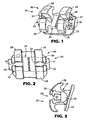
- FIG. 1 An orthodontic appliance constructed in accordance with one embodiment of the present invention is illustrated in Figs. 1-3 and is broadly designated by the numeral 20.
- the appliance 20 in this instance is an orthodontic bracket adapted to be secured to the buccolabial surface of a patient's tooth.
- the appliance could be a molar appliance or any other orthodontic appliance that is adapted to receive an archwire for controlling movement of the teeth during the course of orthodontic therapy.
- the appliance 20 includes a base 22 for bonding the appliance 20 directly to the patient's tooth enamel by use of an adhesive.
- the base 22 has an outwardlyfacing concave compound contour that matches the convex compound contour of the patient's tooth surface.
- the base 22 may be provided with grooves, particles, recesses, undercuts, a chemical bond enhancement material or any other material or structure or any combination of the foregoing that facilitates bonding the appliance 20 directly to the patient's tooth surface.
- a body 24 extends outwardly from the base 22 in a generally buccolabial direction.
- the body 24 includes a spaced-apart pair of mesial tiewings 26 and a pair of spaced-apart distal tiewings 28.
- An archwire slot 30 extends across the body 24 in a generally mesial-distal direction and between the space presented by the pair of mesial tiewings 26 and the space presented between the pair of distal tiewings 28.
- the tiewings 26, 28 may be omitted.
- the body 24 also includes a mesially extending support 31 that is connected to an outermost mesial flange 32 and a distally extending support 33 that is connected to an outermost distal flange 34.
- Each of the flanges 32, 34 has a somewhat semi-circular configuration in elevational view, although other shapes are also possible.
- the flanges 32, 34 are integral with the supports 31, 33 respectively although as another option the flanges 32, 34 may be affixed to the remaining portions of the body 24 after first being separately manufactured.
- the appliance 20 also includes a latch 36 that is connected to the body 24 for releasably retaining an archwire in the archwire slot 30.
- the latch 36 includes a mesial clip 38 and a distal clip 40 although other alternatives are also possible.
- the latch 36 could have only a single clip that is optionally located in the space between the pair of mesial tiewings 26 and the pair of distal tiewings 28.
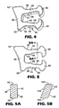
- the distal clip 40 is shown alone in Figs. 4 and 5 and has an overall, generally "C"-shaped configuration.
- the distal clip 40 includes a first section 42 and a second section 44 that is opposed to the first section 42. In their normal, relaxed configuration, the first section 42 and the second section 44 extend in generally parallel directions.
- the first section 42 is spaced apart from the second section 44 to present a region 46 for receiving an archwire.
- the clip 40 also includes a third section 48 that interconnects the first section 42 and the second section 44.
- the third section 48 When assembled to the body 24, the third section 48 extends in a generally occlusal-gingival direction along the buccolabial surface of the base 22 as can be appreciated by reference to Fig. 3 .
- the third section 48 extends beyond the first section 42 and the second section 44 in an occlusal-gingival direction and terminates at a rounded, protruding outermost occlusal corner 50 and a rounded, protruding outermost gingival corner 52.
- the corners 50, 52 contact the buccolabial side of the base 22 when the clip 40 is assembled to the body 24.
- a middle portion of the third section 48 is slightly spaced from the buccolabial side of the base 22.
- the clip 40 also includes a recess 54 that communicates with the archwire-receiving region 46.
- the recess 54 is smaller than the region 46 in directions parallel to the direction of extension of the third section 48, which in turn is generally parallel to an occlusal-gingival reference axis.
- the first and second sections 42, 44 present a pair of opposed protrusions 56 that extend inwardly toward each other.
- the opposite side of the first and second sections 42, 44 also each present a notch 58 that is opposed to the respective, adjacent protrusion 56.
- the clip 40 also has a pair of arm portions 60, 62 that extend inwardly toward each other.
- a buccolabial edge of the arm portions 60, 62 is smoothly curved in an arc about a mesial-distal reference axis.
- this smooth outer curve extends in a gingival direction beyond the gingival side of the first section 42.
- the smooth outer curve extends in an occlusal direction beyond the occlusal side of the second section 44.
- the clip 40 is shown in its normal, relaxed orientation in Figs. 1-5 .
- the arm portions 60, 62 are movable away from each other in order to admit an archwire into the archwire-receiving region 46 when desired.
- the first and second sections 42, 44 bend in respective arcs away from each other in order to enable the arm portions 60, 62 to move apart from each other.
- the smooth, outer curve on the buccolabial side of the arm portions 60, 62 enables the clip 40 to open and admit an archwire into the region 46 by pressing an archwire against the outer curved edges of the arm portions 60, 62.
- the first and second sections 42, 44 deflect away from each other in order to admit the archwire into the region 46.
- the inherent resiliency of the clip 40, and particularly the resiliency of the first and second sections 42, 44 enables the arm portions 60, 62 to spring back toward each other and to their normal, relaxed configuration as shown in the drawings in order to retain the archwire in the archwire slot 30.
- Fig. 5a is a cross-sectional view of the first section 42 of the clip 40. As shown, the shape of this cross-section is rectangular.
- the first section 42 has a longitudinal axis extending generally along a buccolabial-lingual reference axis, and includes occlusal and gingival walls 43 as well as mesial and distal walls 45.
- the walls 43, 45 are substantially perpendicular to each other as is preferred for appliances having a zero angulation.
- a similar orientation of walls is present in other regions of the clip 40, including the second and third sections 44, 48 as well as in the arm portions 60, 62. Although not shown in the drawings, the intersections between the walls are rounded.
- Fig. 5b is a view somewhat similar to Fig. 5a , but showing a section of a clip 140 according to another embodiment of the invention.
- the clip 140 has a shape, when viewed in a mesial or distal direction that is similar to the shape of the clip 40.
- a first section 142 of the clip 140 has occlusal and gingival walls 143 that are oriented at an angle other than 90 degrees relative to mesial and distal walls 145.
- a similar orientation of walls is present at other regions of the clip 140, including in a second and third section as well as in arm portions of the clip.
- the cross-sectional shape of the clip 140 resembles a rhomboid or a parallelogram having no right angles.
- Such construction is a particular advantage when used in combination with appliances known as "angulated" appliances having an archwire slot that extends at a similar angle relative to mesial and distal sides of tiewings and/or the appliance body.
- angulated appliances having an archwire slot that extends at a similar angle relative to mesial and distal sides of tiewings and/or the appliance body.
- the total area occupied by a clip may remain the same without unduly decreasing its cross-sectional area or its resultant strength and fatigue life.
- the clip 40 is preferably put in place before the base 22 is affixed to the body 24.
- the clip 40 is moved in a buccolabial direction in the space between the distal flange 34 and the remaining portions of the body 24 and the arm portions 60, 62 are spread apart a distance sufficient to enable the support 33 to be received in the region 46.
- the clip 40 is then moved further in a buccolabial direction until such time as the support 33 is received in the recess 54.
- the base 22 is affixed to the body 24 by a suitable process such as brazing or welding (including laser welding).
- a suitable process such as brazing or welding (including laser welding).
- the clip 40 (including the first and second sections 42, 44) is sufficiently stiff to retain the archwire in the archwire slot 30 during the course of treatment so long as the forces exerted by the archwire on the appliance 20 are below a certain minimum value in a generally buccolabial direction (more particularly, in a direction opposite to the direction of insertion of the archwire into the archwire slot 30).
- the first and second sections 42, 44 deflect outwardly and the arm portions 60, 62 move apart from each other to open the clip 38 and enable the archwire to be released from the archwire slot 30. Further details regarding such forces are described in the aforementioned PCT applications entitled "ORTHODONTIC APPLIANCE WITH SELF-RELEASING LATCH", WO01/22901 and US02/09896 .
- the clip 38 is identical to the clip 40.
- the latch 36 comprising the clips 38, 40, preferably releases the archwire from the archwire slot 30 in a generally buccolabial direction whenever the archwire exerts a force in the same direction on the appliance 20 that is in the range of about 0.2 lb (0.1 kg) to about 11 lb (5 kg), more preferably in the range of about 0.4 lb (0.2 kg) to about 5.5 lb (2.5 kg), and most preferably in the range of about 0.75 lb (0.34 kg) to about 3.0 lb (1.4 kg).
- the minimum value is sufficiently high to prevent the archwire from unintentionally releasing from the archwire slot 30 during the normal course of orthodontic treatment. As such, the archwire can exert forces on the appliance 20 sufficient to carry out the treatment program and move the associated teeth as desired.
- the minimum value for self-release (i.e., self-opening) of the latch 36 is substantially less than the force required in the same direction to debond the appliance 20 from the associated tooth.
- the minimum value for self-release of the latch 36 is preferably less than about one-half of the force required in the same direction to debond the appliance 20 from the associated tooth. For example, if the expected bond strength of the adhesive bond between the appliance 20 and the associated tooth is 16 lbs (7.2 kg) in a buccolabial direction, the latch 36 is constructed to self-release the archwire whenever the archwire exerts a force in the same buccolabial direction on the appliance 20 that is somewhat greater than about 8 lbs (3.6 kg).
- a section of archwire is selected having an area in longitudinally transverse sections that is complemental to (i.e., substantially fills) the cross-sectional area of the archwire slot 30.
- a sling is constructed and is connected to the archwire section at locations closely adjacent, but not in contact with the mesial flange 32 and the distal flange 34.
- the sling is welded or brazed to the archwire section.
- the sling is pulled away from the appliance 20 while the appliance 20 is held in a stationary position, taking care to ensure that the longitudinal axis of the archwire section does not tip relative to the longitudinal axis of the archwire slot 30.
- the force to release the latch 36 may be determined by use of an Instron testing apparatus connected to the sling, using a crosshead speed of 0.5 in/min (1.3 cm/min).
- a shaker apparatus such as Model 300 from APS Dynamics of Carlsbad, California
- a force transducer such as model 208C01 from PCB of Buffalo, New York
- the self-releasing latch 36 is a benefit to the practitioner, in that the likelihood of spontaneous debonding of the appliance 20 is substantially reduced. For example, if the practitioner attempts to place a relatively large archwire in the archwire slot 30 and the latch 36 self-releases as soon as the practitioner releases the archwire, the practitioner can then use an archwire with less stiffness in its place so that the appliance 20 is not detached from the tooth surface.
- the arm portions 60, 62 spread apart to their slot-open positions to release the archwire so that the appliance 20 does not debond from the tooth. Treatment can then be resumed by merely replacing the archwire in the archwire slot 30 without the need to rebond the base 22 to the associated tooth.
- the distance between the opposed ends of the arm portions 60, 62 is less than the overall occlusal-gingival dimension of the smallest archwire expected to be used during the course of treatment.
- the archwire need not fill the archwire slot 30 and flatly engage the wall portions defining the archwire slot 30 in all instances.
- a somewhat smaller wire, and perhaps an archwire having a circular cross-sectional shape may be used during a portion of the treatment program.
- the distance between the opposed ends of the arm portions 60, 62 is preferably selected so that a variety of archwires of different cross-sectional configurations may be used in connection with the appliance 20.
- the distal clip 40 is identical to the mesial clip 38.
- the spring clips 38, 40 are cut from a flat section of metallic stock material.
- Suitable metallic materials include shape memory alloys such as alloys of nitinol and beta-titanium.
- the clips 38, 40 may be cut from the stock material using a stamping, die cutting, chemical etching, EDM (electrical discharge machining), laser cutting or water jet cutting process.
- the clips 38, 40 could be formed and then heat treated to set their shapes.
- the clips 38, 40 are made from flat annealed superelastic material (such as nitinol) having a pickled surface.
- Preferred nitinol materials have a nickel content of 55.97% by weight A f of 10° ⁇ 5°C.
- the nitinol is cold worked to 37.5% and has a thickness in the range of about 0.012 in. (0.3 mm) to about 0.016 in. (0.4 mm).
- the clips 38, 40 are first cut in a rough cutting EDM process, then cut along their edges for an additional one or more times using an EDM process in order to smooth the edges.
- a laser cutting process or chemical etching process could be used to make the clips 38, 40.
- the clips 38, 40 are constructed so that the longitudinal direction of the clip material, or the principal direction of grain flow of the clip material, is substantially parallel to the direction of extension of the first and second sections 42, 44 (i.e. a generally buccolabial direction).
- the clips 38, 40 are tumbled in order to further round their edges.
- An example of a suitable tumbling machine is model LC-600-2+2 from Richwood Industries. Using a small barrel, and a machine speed of 200 rpm, the clips are tumbled for about 2 hours in 500 cc of water and tumbling media.
- An example of suitable tumbling media is a mixture of 500 cc of ceramic media (shaped ACC, type M, size 3/16 X 3/8 (4.7 mm X 9.5 mm), 25 cc of white alumina powder no. 40, and 25 cc of soap powder compound no. 43, all from Richwood Industries.
- the tumbled clips are then polished for one-half hour in an ultrasonic screen barrel in a tank of solution.
- An example of a suitable solution is 3 liters of deionized water, 3 liters of pickling solution and 0.6 liter of hydrogen peroxide.
- a suitable pickling solution is No. TI121 Pickling Solution from Aya International of Los Angeles, California.
- the shape of the clip 38 as shown in Figs. 4 and 5 reduces maximum strain and stress during opening and closing movements so that the expected useful life of the clip 38 is increased.
- the decrease in width of the first and second sections 42, 44 as the arm portions 60, 62 respectively are approached serves to reduce maximum strain to significantly lower levels.
- this width is a dimension that is determined along an occlusal-gingival reference axis and the decrease in width is carried out gradually as the arm portions 60, 62 are approached.
- the provision of the recess 54 also helps to reduce maximum strain and stress when the clip 38 is opened during assembly of the appliance 20.
- the provision of the notches 58 helps to safely provide a gradual decrease in width while enabling the recess 54 to be smaller than the region 46 in directions along an occlusal-gingival reference axis.
- careful selection of the overall shape of the perimeter of the first and second sections 42, 44 helped to reduce maximum strain from 0.116 to 0.067 and maximum stress from 98,700 psi to 75,200 psi.
- the third section 48 extends in a direction other than 90 degrees from the direction of extension of the first and second sections 42, 44 when the clip 38 is in its normally relaxed orientation. Additionally, a hypothetical reference plane resting on an outer edge of the third section 48 extends in a direction other than 90 degrees from the direction of extension of the first and second sections 42, 44 when the clip 38 is in its normally relaxed configuration. Such construction is particularly useful for brackets having what is known as "torque-in-base" as shown in Figs. 1-3 .
- the torque-in-base appliance has an archwire slot with a lingual wall that is oriented at an acute angle relative to the overall orientation of the base 22.
- the orientation of the third section 48 helps ensure that the corners 50, 52 firmly bear against the buccolabial side of the base 22 once the clip 38 is assembled to remaining components of the appliance 20.
- the reference plane mentioned above extends at a substantially 90 degree direction from the direction of the first and second sections 42, 44, but in those instances it is also preferred that the corners 50, 52 firmly bear against the buccolabial side of the base 22.
- the body 24 may be made by any suitable manufacturing process such as machining or injection molding (including metal injection molding). Suitable materials for the body 24 include stainless steel nos. 17-4 PH, although other materials are also possible. Preferably, the tumbling and heat treating operations are carried out after the body 24 is fabricated.
- the appliance 20a includes an aesthetic ceramic body 24a that is preferably integrally connected to an aesthetic ceramic base 22a.
- the body 24a includes mesial and distal body sections 25a, 27a respectively and is somewhat similar to the appliances described in U.S. Patent Nos. 5,439,379 and 5,366,372 ,.
- the appliance 20a also includes a metallic archwire slot liner 29a that defines an archwire slot 30a.
- a mesial and distal elongated support 31a, 33a are fixed to a lingual side of the archwire slot liner 29a.
- the supports 31a, 33a are made of a metallic material that is brazed or welded to the archwire slot liner 29a.
- the mesial support 31a is integrally connected to a mesial flange 32a and the distal support 33a is integrally connected to a distal flange 34a.
- the clips 38a, 40a comprise a latch 36a for releasably retaining an archwire in the archwire slot 30a.
- the clips 38a, 40a are moved relative to the supports 31a, 33a until such time as the supports 31a, 33a are received recesses of the clips 38a, 40a.
- the combination of the archwire slot liner 29a, the supports 31a, 33a and the clips 38a, 40a is set in place on the body 24a such that the archwire slot liner 29a is received in a mesial-distal channel that extends through the body sections 25a, 27a.
- the archwire slot liner 29a and optionally also the supports 31a, 33a are fixed to the ceramic body 24a, preferably according to the methods described in U.S. Patent Nos. 5,358,402 and 5,380,196 as mentioned above.
- the supports 31a, 33a may be fixed to the liner 29a before the liner 29a is secured to the body 24a.
- the clips 38a, 40a are the same as the clips 38 and 40 set out above. Accordingly, a detailed description of the construction of the clips 38a, 40a need not be repeated.
Claims (11)
- Appareil orthodontique (20), comprenant une base (22, 22a) pour attacher l'appareil à une dent, un corps (24, 24a) qui s'étend à partir de la base, une fente pour fil d'arcade (30, 30a) qui s'étend en travers du corps dans une direction essentiellement mésiale - distale, un support (31, 33, 31a, 33a), et un verrou (36) qui est connecté au corps afin de retenir de façon détachable un fil d'arcade dans la fente pour fil d'arcade, le verrou comprenant au moins une attache (38, 40, 140), comprenant:une première section (42);une deuxième section (44) opposée à la première section, la première section et la deuxième section étant espacées l'une de l'autre de manière à présenter une région (46) destinée à recevoir un fil d'arcade;une troisième section (48) qui s'étend dans une direction essentiellement parallèle à un axe de référence occlusal - gingival et qui interconnecte la première section et la deuxième section;une première partie de bras (60) qui est connectée à la première section à distance de la troisième section;une deuxième partie de bras (62) qui est connectée à la deuxième section à distance de la troisième section, dans lequel les parties de bras sont déplaçables l'une vers l'autre et à l'écart l'une de l'autre afin de retenir et de relâcher un fil d'arcade dans la région entre la première section et la deuxième section, respectivement, etcaractérisé en ce que ladite au moins une attache (38, 40, 140) comprend:un évidement (54) à proximité de la troisième section et qui communique avec la région de réception de fil d'arcade (46), dans lequel le support s'étend à travers l'évidement, l'évidement étant plus petit que la région de réception de fil d'arcade (46) dans des zones proches de la région de réception de fil d'arcade (46) dans des directions parallèles à la direction d'extension de la troisième section.
- Appareil orthodontique selon la revendication 1, dans lequel la première section et la deuxième section s'étendent dans des directions essentiellement parallèles, dans lequel la troisième section présente un bord extérieur distant de la première section et de la deuxième section, et dans lequel un plan de référence qui se situe sur le bord extérieur s'étend à un angle autre que 90 degrés par rapport à la direction d'extension de la première section et de la deuxième section.
- Appareil orthodontique selon la revendication 1, dans lequel la largeur de la première section diminue lorsque la première partie de bras est approchée, et la largeur de la deuxième section diminue lorsque la deuxième partie de bras est approchée.
- Appareil orthodontique selon la revendication 1, dans lequel la troisième section présente des coins extérieurs (50, 52) qui s'étendent au-delà de la première section et de la deuxième section dans ladite certaine direction.
- Appareil orthodontique selon la revendication 1, dans lequel la première section et la deuxième section sont essentiellement des images inverses.
- Appareil orthodontique selon la revendication 1, dans lequel la première partie de bras présente un coin extérieur qui s'étend au-delà de la première section dans ladite certaine direction, et dans lequel la deuxième partie de bras présente un coin extérieur qui s'étend au-delà de la deuxième section dans la certaine direction.
- Appareil orthodontique selon la revendication 1, dans lequel l'appareil comprend une attache mésiale à proximité d'un côté mésial du corps, et une attache distale (40, 40a) à proximité d'un côté distal du corps.
- Appareil orthodontique selon la revendication 1, dans lequel la troisième section comporte un bord extérieur qui présente une configuration concave.
- Appareil orthodontique selon la revendication 1, dans lequel les première et deuxième sections comportent des première et deuxième saillies opposées (56) à proximité de l'évidement, les première et deuxième saillies s'étendant vers l'intérieur en direction l'une de l'autre.
- Appareil orthodontique selon la revendication 1, dans lequel la première section et la deuxième section sont déplaçables l'une vers l'autre et à l'écart l'une de l'autre de manière à permettre aux parties de bras de retenir et de relâcher un fil d'arcade dans la région entre la première section et la deuxième section, respectivement.
- Appareil orthodontique selon la revendication 10, dans lequel la largeur de la première section diminue après la région lorsque la première partie de bras est approchée, et la largeur de la deuxième section diminue après la région lorsque la deuxième partie de bras est approchée.
Applications Claiming Priority (3)
| Application Number | Priority Date | Filing Date | Title |
|---|---|---|---|
| US287089 | 2002-11-04 | ||
| US10/287,089 US7014460B2 (en) | 2002-11-04 | 2002-11-04 | Orthodontic appliance with fatigue-resistant archwire retaining latch |
| PCT/US2003/028168 WO2004041109A2 (fr) | 2002-11-04 | 2003-09-09 | Appareil orthodontique avec verrou de retenue d'arc resistant a la fatigue |
Publications (2)
| Publication Number | Publication Date |
|---|---|
| EP1558167A2 EP1558167A2 (fr) | 2005-08-03 |
| EP1558167B1 true EP1558167B1 (fr) | 2011-12-28 |
Family
ID=32175604
Family Applications (1)
| Application Number | Title | Priority Date | Filing Date |
|---|---|---|---|
| EP03749529A Expired - Lifetime EP1558167B1 (fr) | 2002-11-04 | 2003-09-09 | Appareil orthodontique avec verrou de retenue d'arc resistant a la fatigue |
Country Status (6)
| Country | Link |
|---|---|
| US (1) | US7014460B2 (fr) |
| EP (1) | EP1558167B1 (fr) |
| JP (2) | JP2006505327A (fr) |
| AT (1) | ATE538751T1 (fr) |
| AU (1) | AU2003268557A1 (fr) |
| WO (1) | WO2004041109A2 (fr) |
Families Citing this family (34)
| Publication number | Priority date | Publication date | Assignee | Title |
|---|---|---|---|---|
| US6957957B2 (en) * | 2002-11-04 | 2005-10-25 | 3M Innovative Properties Company | Molar appliance for orthodontic therapy |
| US7140876B2 (en) | 2003-10-31 | 2006-11-28 | 3M Innovative Properties Company | Orthodontic appliance with latch for retaining an archwire |
| US7192274B2 (en) * | 2003-12-08 | 2007-03-20 | 3M Innovative Properties Company | Ceramic orthodontic appliance with archwire slot liner |
| US7252505B2 (en) * | 2004-07-28 | 2007-08-07 | 3M Innovative Properties Company | Self-ligating orthodontic appliance with post for connection to a latch |
| US20060024634A1 (en) * | 2004-07-28 | 2006-02-02 | 3M Innovative Properties Company | Self-ligating orthodontic appliance with clip |
| BRMU8402119U (pt) * | 2004-09-03 | 2006-04-25 | Daniel Ianni Jr | disposição aplicada em braquete bipartido com articulação ajustável |
| US7329120B1 (en) | 2004-10-25 | 2008-02-12 | Cannon James L | Orthodontic bracket with vertical slot and method of using same |
| US7367800B2 (en) * | 2005-02-02 | 2008-05-06 | 3M Innovative Properties Company | Pre-torqued orthodontic appliance with archwire retaining latch |
| US20070009849A1 (en) * | 2005-07-11 | 2007-01-11 | Wool Arthur L | Self-locking orthodontic bracket |
| US7377777B2 (en) * | 2005-12-23 | 2008-05-27 | 3M Innovative Properties Company | Orthodontic appliance with archwire-engaging clip |
| US20070172788A1 (en) * | 2006-01-20 | 2007-07-26 | Hill Ii Charles F | Hybrid orthodontic archwire |
| US8267686B2 (en) * | 2006-09-29 | 2012-09-18 | 3M Innovative Properties Company | Orthodontic bracket with brazed archwire slot liner |
| US20080138757A1 (en) * | 2006-12-12 | 2008-06-12 | 3M Innovative Properties Company | Orthodontic brace with reduced profile |
| US7837466B2 (en) * | 2007-04-08 | 2010-11-23 | Griffith Richard J | Orthodontic apparatus and method |
| JP5215381B2 (ja) * | 2007-04-30 | 2013-06-19 | スリーエム イノベイティブ プロパティズ カンパニー | 改善された剥離特性を有するセラミック製歯科矯正ブラケット |
| US7686613B2 (en) | 2007-07-10 | 2010-03-30 | 3M Innovative Properties Company | Narrow ceramic self-ligating orthodontic bracket |
| US7857618B2 (en) * | 2007-11-27 | 2010-12-28 | Ultradent Products, Inc. | Orthodontic bracket including mechanism for reducing slot width for early torque control |
| EP2266495A1 (fr) | 2008-03-18 | 2010-12-29 | Dentsply-Sankin K.K. | Appareil orthodontique |
| US8827697B2 (en) | 2008-04-09 | 2014-09-09 | 3M Innovative Properties Company | Lingual orthodontic appliance with removable section |
| JP5770630B2 (ja) | 2008-08-13 | 2015-08-26 | オルムコ コーポレイション | 審美的歯列矯正ブラケット及びその製造方法 |
| AU2009238317B2 (en) | 2008-11-14 | 2011-10-06 | Ormco Corporation | Surface treated polycrystalline ceramic orthodontic bracket and method of making same |
| US20100229280A1 (en) * | 2009-03-13 | 2010-09-16 | Constance Kaiserman Robinson | Shared hand mitten-type garment |
| CN103732176A (zh) | 2011-02-11 | 2014-04-16 | 欧瑟阿尔穆公司 | 口腔正畸托架 |
| US8834156B2 (en) * | 2011-05-16 | 2014-09-16 | Ortho Organizers, Inc. | Orthodontic bracket system |
| EP2644150B1 (fr) | 2012-03-28 | 2019-01-23 | Orthoarm, Inc. | Support actif à ligature automatique |
| US9585733B2 (en) | 2012-03-28 | 2017-03-07 | Orthoarm, Inc. | Orthodontic bracket with angled, curved shutter |
| JP2018507751A (ja) | 2015-03-13 | 2018-03-22 | スリーエム イノベイティブ プロパティズ カンパニー | アーチ部材を含む歯科矯正装置 |
| KR20170128376A (ko) | 2015-03-13 | 2017-11-22 | 쓰리엠 이노베이티브 프로퍼티즈 컴파니 | 아치 부재를 포함하는 치과교정용 기구 |
| US11452578B2 (en) | 2015-05-14 | 2022-09-27 | Cosmo Haralambidis | Orthodontic retention components, kit and system |
| US10098710B2 (en) | 2015-05-14 | 2018-10-16 | Cosmo Haralambidis | Orthodontic retention components, kit and system |
| US11179226B2 (en) * | 2015-12-21 | 2021-11-23 | Premier Orthodontic Designs Lllp | Orthodontic bracket |
| EP3407825B1 (fr) * | 2016-01-29 | 2020-04-15 | 3M Innovative Properties Company | Attache orthodontique et procédé de fabrication d'une attache orthodontique |
| EP3407824B1 (fr) * | 2016-01-29 | 2020-04-15 | 3M Innovative Properties Company | Appareil orthodontique lingual |
| WO2018136407A1 (fr) * | 2017-01-19 | 2018-07-26 | Dischinger Terry G | Procédé et appareil de traitement de malocclusions et d'alignement des dents |
Family Cites Families (54)
| Publication number | Priority date | Publication date | Assignee | Title |
|---|---|---|---|---|
| US1991047A (en) * | 1933-01-17 | 1935-02-12 | Boyd Charles Edward | Orthodontia band bracket |
| US3052027A (en) * | 1960-01-20 | 1962-09-04 | Wallshein Melvin | Orthodontic appliances |
| US3084437A (en) * | 1960-04-07 | 1963-04-09 | Neger Milton | Orthodontic appliance |
| US3327393A (en) * | 1964-06-16 | 1967-06-27 | Allen C Brader | Orthodontic arch wire edgewise brackets |
| US3464113A (en) * | 1966-08-03 | 1969-09-02 | Elliott Silverman | Orthodontic appliance |
| US3464112A (en) * | 1967-06-30 | 1969-09-02 | Elliott Silverman | Orthodontic appliance |
| US3724074A (en) * | 1971-02-22 | 1973-04-03 | M Wallshein | Brackets for supporting arch wires, and adapted to function in orthodontic procedures in systems for tilting, uprighting and turning teeth |
| US3772787A (en) * | 1972-03-17 | 1973-11-20 | G Hanson | Orthodontic bracket |
| CH619611A5 (fr) * | 1977-01-17 | 1980-10-15 | Foerster Bernhard Fa | |
| US4149314A (en) * | 1977-02-18 | 1979-04-17 | Nonnenmann Michael J | Orthodontic brackets with pivotal fastenings |
| US4103423A (en) * | 1977-03-04 | 1978-08-01 | Kessel Stanley P | Orthodontic bracket |
| US4197642A (en) * | 1977-09-29 | 1980-04-15 | Melvin Wallshein | Bent wire orthodontic spring clip |
| US4248588A (en) * | 1979-04-27 | 1981-02-03 | Hanson Gustaf H | Orthodontic bracket and arch wire |
| US4260375A (en) * | 1979-12-13 | 1981-04-07 | Melvin Wallshein | Bent wire orthodontic spring clip |
| US4371337A (en) * | 1981-05-20 | 1983-02-01 | Pletcher Erwin Carroll | Orthodontic bracket |
| US4496318A (en) * | 1982-05-17 | 1985-01-29 | Connelly Jr Harold R | Converters for orthodontic treatment |
| US4492573A (en) * | 1984-03-27 | 1985-01-08 | Augusta Developments Inc. | Orthodontic bracket |
| US4559012A (en) * | 1984-12-06 | 1985-12-17 | Pletcher Erwin Carroll | Orthodontic bracket |
| US4551094A (en) * | 1985-01-31 | 1985-11-05 | Kesling Peter C | Edgewise bracket wire retaining clip |
| US4725229A (en) * | 1986-06-18 | 1988-02-16 | Ormco Corporation | Orthodontic bracket |
| US4712999A (en) * | 1986-09-10 | 1987-12-15 | Farel Rosenberg | Convertible, self-ligating, archwire positioning orthodontic bracket |
| US4698017A (en) * | 1986-12-10 | 1987-10-06 | Hanson Gustaf H | Orthodontic brackets |
| US4846681A (en) * | 1988-03-07 | 1989-07-11 | Mourany Haitham E | Orthodontic bracket |
| US5474444A (en) * | 1988-09-26 | 1995-12-12 | Wildman; Alexander J. | Multiwire arch system |
| US5039302A (en) * | 1990-02-01 | 1991-08-13 | Johnson & Johnson Consumer Products, Inc. | Dental bracket instrument |
| US5094614A (en) * | 1991-03-08 | 1992-03-10 | Wildman Alexander J | Miniature self-locking labial bracket |
| US5269681A (en) * | 1992-05-15 | 1993-12-14 | Degnan Edward V | Integrated ligature and orthodontic bracket |
| US5322435A (en) * | 1992-07-23 | 1994-06-21 | Pletcher Erwin Carroll | Orthodontic bracket |
| JPH0626814U (ja) * | 1992-09-01 | 1994-04-12 | 和也 渡辺 | 矯正歯科用ブラケット |
| US5630715A (en) * | 1993-01-21 | 1997-05-20 | Voudouris; John C. | Orthodontic bracket with an engagement mechanism for retaining an archwire |
| US5466151A (en) * | 1993-04-08 | 1995-11-14 | Damon Family Limited Partnership | Spring-locked orthodontic bracket |
| US5358402A (en) * | 1993-05-13 | 1994-10-25 | Minnesota Mining & Manufacturing Company | Ceramic orthodontic bracket with archwire slot liner |
| US5380196A (en) * | 1993-05-13 | 1995-01-10 | Minnesota Mining And Manufacturing Company | Orthodontic bracket with archwire slot liner |
| US5366372A (en) * | 1993-11-29 | 1994-11-22 | Minnesota Mining And Manufacturing Company | Method and apparatus for debonding ceramic orthodontic brackets |
| US5439379A (en) * | 1993-11-29 | 1995-08-08 | Minnesota Mining And Manufacturing Company | Ceramic orthodontic bracket with debonding channel |
| DE4407100C2 (de) * | 1994-03-03 | 1997-11-13 | Wolfgang Dr Med Heiser | Bracket für kieferorthopädische Behandlungen |
| US5474445A (en) * | 1994-03-07 | 1995-12-12 | John Voudouris | Self-engaging twin edge-wise orthodontic bracket with pivotal latch |
| US5908293A (en) * | 1994-03-07 | 1999-06-01 | Voudouris; John C. | Orthodontic bracket |
| US5913680A (en) | 1994-03-07 | 1999-06-22 | Voudouris; John C. | Orthodontic bracket |
| US5857850A (en) * | 1994-03-07 | 1999-01-12 | Voudouris; John C. | Orthodontic appliance |
| US5474446A (en) * | 1994-07-06 | 1995-12-12 | Wildman; Alexander J. | Miniature self-locking labial bracket with cam-release closure member |
| US5700145A (en) * | 1995-06-05 | 1997-12-23 | Wildman; Alexander J. | Lingual bracket with hinged camming closure and releasable lock |
| US5685711A (en) * | 1995-12-06 | 1997-11-11 | Hanson; G. Herbert | Self-ligating orthodontic brackets |
| US5630716A (en) * | 1995-12-29 | 1997-05-20 | Hanson; G. Herbert | Self-ligating orthodontic brackets |
| DE29608349U1 (de) | 1996-05-08 | 1996-09-26 | Foerster Bernhard Gmbh | Orthodontisches Bracket aus Kunststoff |
| US5711666A (en) * | 1996-10-22 | 1998-01-27 | Hanson; G. Herbert | Self-ligating orthodontic brackets |
| US5857849A (en) * | 1996-12-06 | 1999-01-12 | Kurz; Craven | Self-ligating low profile orthodontic bracket |
| US6168428B1 (en) * | 1997-11-12 | 2001-01-02 | John C. Voudouris | Orthodontic bracket |
| US5890893A (en) * | 1998-02-26 | 1999-04-06 | Heiser; Wolfgang | Orthodontic bracket |
| US5967773A (en) * | 1998-12-22 | 1999-10-19 | Orthodontic Design & Production | Orthodontic bracket with spring cover |
| US6582226B2 (en) | 1999-09-27 | 2003-06-24 | 3M Innovative Properties Company | Orthodontic appliance with self-releasing latch |
| US6302688B1 (en) | 1999-09-27 | 2001-10-16 | 3M Innovative Properties Company | Orthodontic appliance with self-releasing latch |
| JP4444410B2 (ja) | 1999-10-08 | 2010-03-31 | トミー株式会社 | 歯列矯正ブラケットおよび歯列矯正ブラケット用ツール |
| US6554612B2 (en) * | 2001-06-25 | 2003-04-29 | 3M Innovative Properties Company | Orthodontic bracket with recessed attachment and method for making the same |
-
2002
- 2002-11-04 US US10/287,089 patent/US7014460B2/en not_active Expired - Lifetime
-
2003
- 2003-09-09 EP EP03749529A patent/EP1558167B1/fr not_active Expired - Lifetime
- 2003-09-09 JP JP2004549944A patent/JP2006505327A/ja not_active Withdrawn
- 2003-09-09 AT AT03749529T patent/ATE538751T1/de active
- 2003-09-09 AU AU2003268557A patent/AU2003268557A1/en not_active Abandoned
- 2003-09-09 WO PCT/US2003/028168 patent/WO2004041109A2/fr active Application Filing
-
2010
- 2010-07-29 JP JP2010170835A patent/JP4669074B2/ja not_active Expired - Fee Related
Also Published As
| Publication number | Publication date |
|---|---|
| ATE538751T1 (de) | 2012-01-15 |
| WO2004041109A3 (fr) | 2004-08-26 |
| JP2010234145A (ja) | 2010-10-21 |
| US20040086825A1 (en) | 2004-05-06 |
| US7014460B2 (en) | 2006-03-21 |
| EP1558167A2 (fr) | 2005-08-03 |
| JP4669074B2 (ja) | 2011-04-13 |
| AU2003268557A8 (en) | 2004-06-07 |
| WO2004041109A2 (fr) | 2004-05-21 |
| AU2003268557A1 (en) | 2004-06-07 |
| JP2006505327A (ja) | 2006-02-16 |
Similar Documents
| Publication | Publication Date | Title |
|---|---|---|
| EP1558167B1 (fr) | Appareil orthodontique avec verrou de retenue d'arc resistant a la fatigue | |
| EP1796574B1 (fr) | Appareil orthodontique a auto-ligaturage avec attache | |
| EP1778122B1 (fr) | Appareil orthodontique d'auto-ligaturage avec montant de raccord a un taquet | |
| EP1843716B1 (fr) | Appareil orthodontique a application prealable de couple dote d'un dispositif de verrouillage retenant un arc dentaire | |
| US6582226B2 (en) | Orthodontic appliance with self-releasing latch | |
| EP1962714B1 (fr) | Appareilage orthodontique avec clip entrant en prise avec un arc | |
| EP1558168B1 (fr) | Appareil molaire de traitement orthodontique | |
| US20170128169A1 (en) | Low profile self-ligating orthodontic appliance with clip | |
| EP1605860B1 (fr) | Arc orthodontique pourvu d'appareils à autolibération | |
| US7140876B2 (en) | Orthodontic appliance with latch for retaining an archwire |
Legal Events
| Date | Code | Title | Description |
|---|---|---|---|
| PUAI | Public reference made under article 153(3) epc to a published international application that has entered the european phase |
Free format text: ORIGINAL CODE: 0009012 |
|
| 17P | Request for examination filed |
Effective date: 20050511 |
|
| AK | Designated contracting states |
Kind code of ref document: A2 Designated state(s): AT BE BG CH CY CZ DE DK EE ES FI FR GB GR HU IE IT LI LU MC NL PT RO SE SI SK TR |
|
| AX | Request for extension of the european patent |
Extension state: AL LT LV MK |
|
| DAX | Request for extension of the european patent (deleted) | ||
| 17Q | First examination report despatched |
Effective date: 20101008 |
|
| GRAP | Despatch of communication of intention to grant a patent |
Free format text: ORIGINAL CODE: EPIDOSNIGR1 |
|
| GRAS | Grant fee paid |
Free format text: ORIGINAL CODE: EPIDOSNIGR3 |
|
| GRAA | (expected) grant |
Free format text: ORIGINAL CODE: 0009210 |
|
| AK | Designated contracting states |
Kind code of ref document: B1 Designated state(s): AT BE BG CH CY CZ DE DK EE ES FI FR GB GR HU IE IT LI LU MC NL PT RO SE SI SK TR |
|
| REG | Reference to a national code |
Ref country code: GB Ref legal event code: FG4D |
|
| REG | Reference to a national code |
Ref country code: CH Ref legal event code: EP |
|
| REG | Reference to a national code |
Ref country code: AT Ref legal event code: REF Ref document number: 538751 Country of ref document: AT Kind code of ref document: T Effective date: 20120115 |
|
| REG | Reference to a national code |
Ref country code: IE Ref legal event code: FG4D |
|
| REG | Reference to a national code |
Ref country code: DE Ref legal event code: R096 Ref document number: 60339555 Country of ref document: DE Effective date: 20120308 |
|
| REG | Reference to a national code |
Ref country code: NL Ref legal event code: VDEP Effective date: 20111228 |
|
| PG25 | Lapsed in a contracting state [announced via postgrant information from national office to epo] |
Ref country code: GR Free format text: LAPSE BECAUSE OF FAILURE TO SUBMIT A TRANSLATION OF THE DESCRIPTION OR TO PAY THE FEE WITHIN THE PRESCRIBED TIME-LIMIT Effective date: 20120329 Ref country code: SI Free format text: LAPSE BECAUSE OF FAILURE TO SUBMIT A TRANSLATION OF THE DESCRIPTION OR TO PAY THE FEE WITHIN THE PRESCRIBED TIME-LIMIT Effective date: 20111228 Ref country code: SE Free format text: LAPSE BECAUSE OF FAILURE TO SUBMIT A TRANSLATION OF THE DESCRIPTION OR TO PAY THE FEE WITHIN THE PRESCRIBED TIME-LIMIT Effective date: 20111228 |
|
| PG25 | Lapsed in a contracting state [announced via postgrant information from national office to epo] |
Ref country code: CY Free format text: LAPSE BECAUSE OF FAILURE TO SUBMIT A TRANSLATION OF THE DESCRIPTION OR TO PAY THE FEE WITHIN THE PRESCRIBED TIME-LIMIT Effective date: 20111228 Ref country code: BE Free format text: LAPSE BECAUSE OF FAILURE TO SUBMIT A TRANSLATION OF THE DESCRIPTION OR TO PAY THE FEE WITHIN THE PRESCRIBED TIME-LIMIT Effective date: 20111228 |
|
| PG25 | Lapsed in a contracting state [announced via postgrant information from national office to epo] |
Ref country code: EE Free format text: LAPSE BECAUSE OF FAILURE TO SUBMIT A TRANSLATION OF THE DESCRIPTION OR TO PAY THE FEE WITHIN THE PRESCRIBED TIME-LIMIT Effective date: 20111228 Ref country code: BG Free format text: LAPSE BECAUSE OF FAILURE TO SUBMIT A TRANSLATION OF THE DESCRIPTION OR TO PAY THE FEE WITHIN THE PRESCRIBED TIME-LIMIT Effective date: 20120328 Ref country code: CZ Free format text: LAPSE BECAUSE OF FAILURE TO SUBMIT A TRANSLATION OF THE DESCRIPTION OR TO PAY THE FEE WITHIN THE PRESCRIBED TIME-LIMIT Effective date: 20111228 Ref country code: NL Free format text: LAPSE BECAUSE OF FAILURE TO SUBMIT A TRANSLATION OF THE DESCRIPTION OR TO PAY THE FEE WITHIN THE PRESCRIBED TIME-LIMIT Effective date: 20111228 Ref country code: SK Free format text: LAPSE BECAUSE OF FAILURE TO SUBMIT A TRANSLATION OF THE DESCRIPTION OR TO PAY THE FEE WITHIN THE PRESCRIBED TIME-LIMIT Effective date: 20111228 |
|
| PG25 | Lapsed in a contracting state [announced via postgrant information from national office to epo] |
Ref country code: PT Free format text: LAPSE BECAUSE OF FAILURE TO SUBMIT A TRANSLATION OF THE DESCRIPTION OR TO PAY THE FEE WITHIN THE PRESCRIBED TIME-LIMIT Effective date: 20120430 Ref country code: RO Free format text: LAPSE BECAUSE OF FAILURE TO SUBMIT A TRANSLATION OF THE DESCRIPTION OR TO PAY THE FEE WITHIN THE PRESCRIBED TIME-LIMIT Effective date: 20111228 |
|
| REG | Reference to a national code |
Ref country code: AT Ref legal event code: MK05 Ref document number: 538751 Country of ref document: AT Kind code of ref document: T Effective date: 20111228 |
|
| PG25 | Lapsed in a contracting state [announced via postgrant information from national office to epo] |
Ref country code: DK Free format text: LAPSE BECAUSE OF FAILURE TO SUBMIT A TRANSLATION OF THE DESCRIPTION OR TO PAY THE FEE WITHIN THE PRESCRIBED TIME-LIMIT Effective date: 20111228 |
|
| PGFP | Annual fee paid to national office [announced via postgrant information from national office to epo] |
Ref country code: GB Payment date: 20120905 Year of fee payment: 10 |
|
| PLBE | No opposition filed within time limit |
Free format text: ORIGINAL CODE: 0009261 |
|
| STAA | Information on the status of an ep patent application or granted ep patent |
Free format text: STATUS: NO OPPOSITION FILED WITHIN TIME LIMIT |
|
| 26N | No opposition filed |
Effective date: 20121001 |
|
| REG | Reference to a national code |
Ref country code: DE Ref legal event code: R097 Ref document number: 60339555 Country of ref document: DE Effective date: 20121001 |
|
| PG25 | Lapsed in a contracting state [announced via postgrant information from national office to epo] |
Ref country code: AT Free format text: LAPSE BECAUSE OF FAILURE TO SUBMIT A TRANSLATION OF THE DESCRIPTION OR TO PAY THE FEE WITHIN THE PRESCRIBED TIME-LIMIT Effective date: 20111228 |
|
| PG25 | Lapsed in a contracting state [announced via postgrant information from national office to epo] |
Ref country code: MC Free format text: LAPSE BECAUSE OF NON-PAYMENT OF DUE FEES Effective date: 20120930 Ref country code: ES Free format text: LAPSE BECAUSE OF FAILURE TO SUBMIT A TRANSLATION OF THE DESCRIPTION OR TO PAY THE FEE WITHIN THE PRESCRIBED TIME-LIMIT Effective date: 20120408 |
|
| REG | Reference to a national code |
Ref country code: CH Ref legal event code: PL |
|
| REG | Reference to a national code |
Ref country code: IE Ref legal event code: MM4A |
|
| PG25 | Lapsed in a contracting state [announced via postgrant information from national office to epo] |
Ref country code: FI Free format text: LAPSE BECAUSE OF FAILURE TO SUBMIT A TRANSLATION OF THE DESCRIPTION OR TO PAY THE FEE WITHIN THE PRESCRIBED TIME-LIMIT Effective date: 20111228 |
|
| PG25 | Lapsed in a contracting state [announced via postgrant information from national office to epo] |
Ref country code: IE Free format text: LAPSE BECAUSE OF NON-PAYMENT OF DUE FEES Effective date: 20120909 Ref country code: CH Free format text: LAPSE BECAUSE OF NON-PAYMENT OF DUE FEES Effective date: 20120930 Ref country code: LI Free format text: LAPSE BECAUSE OF NON-PAYMENT OF DUE FEES Effective date: 20120930 |
|
| PG25 | Lapsed in a contracting state [announced via postgrant information from national office to epo] |
Ref country code: TR Free format text: LAPSE BECAUSE OF FAILURE TO SUBMIT A TRANSLATION OF THE DESCRIPTION OR TO PAY THE FEE WITHIN THE PRESCRIBED TIME-LIMIT Effective date: 20111228 |
|
| GBPC | Gb: european patent ceased through non-payment of renewal fee |
Effective date: 20130909 |
|
| PG25 | Lapsed in a contracting state [announced via postgrant information from national office to epo] |
Ref country code: LU Free format text: LAPSE BECAUSE OF NON-PAYMENT OF DUE FEES Effective date: 20120909 |
|
| PG25 | Lapsed in a contracting state [announced via postgrant information from national office to epo] |
Ref country code: GB Free format text: LAPSE BECAUSE OF NON-PAYMENT OF DUE FEES Effective date: 20130909 Ref country code: HU Free format text: LAPSE BECAUSE OF FAILURE TO SUBMIT A TRANSLATION OF THE DESCRIPTION OR TO PAY THE FEE WITHIN THE PRESCRIBED TIME-LIMIT Effective date: 20030909 |
|
| REG | Reference to a national code |
Ref country code: FR Ref legal event code: PLFP Year of fee payment: 13 |
|
| REG | Reference to a national code |
Ref country code: FR Ref legal event code: PLFP Year of fee payment: 14 |
|
| REG | Reference to a national code |
Ref country code: FR Ref legal event code: PLFP Year of fee payment: 15 |
|
| REG | Reference to a national code |
Ref country code: FR Ref legal event code: PLFP Year of fee payment: 16 |
|
| PGFP | Annual fee paid to national office [announced via postgrant information from national office to epo] |
Ref country code: IT Payment date: 20190917 Year of fee payment: 17 Ref country code: FR Payment date: 20190815 Year of fee payment: 17 |
|
| PG25 | Lapsed in a contracting state [announced via postgrant information from national office to epo] |
Ref country code: FR Free format text: LAPSE BECAUSE OF NON-PAYMENT OF DUE FEES Effective date: 20200930 |
|
| PG25 | Lapsed in a contracting state [announced via postgrant information from national office to epo] |
Ref country code: IT Free format text: LAPSE BECAUSE OF NON-PAYMENT OF DUE FEES Effective date: 20200909 |
|
| PGFP | Annual fee paid to national office [announced via postgrant information from national office to epo] |
Ref country code: DE Payment date: 20210818 Year of fee payment: 19 |
|
| REG | Reference to a national code |
Ref country code: DE Ref legal event code: R119 Ref document number: 60339555 Country of ref document: DE |
|
| PG25 | Lapsed in a contracting state [announced via postgrant information from national office to epo] |
Ref country code: DE Free format text: LAPSE BECAUSE OF NON-PAYMENT OF DUE FEES Effective date: 20230401 |