EP2328397B1 - Déflecteur de débris pour coupeuse rotative - Google Patents
Déflecteur de débris pour coupeuse rotative Download PDFInfo
- Publication number
- EP2328397B1 EP2328397B1 EP09766178.9A EP09766178A EP2328397B1 EP 2328397 B1 EP2328397 B1 EP 2328397B1 EP 09766178 A EP09766178 A EP 09766178A EP 2328397 B1 EP2328397 B1 EP 2328397B1
- Authority
- EP
- European Patent Office
- Prior art keywords
- mounting member
- assembly
- cutter
- rib
- cutter mounting
- Prior art date
- Legal status (The legal status is an assumption and is not a legal conclusion. Google has not performed a legal analysis and makes no representation as to the accuracy of the status listed.)
- Active
Links
Images


Classifications
-
- A—HUMAN NECESSITIES
- A01—AGRICULTURE; FORESTRY; ANIMAL HUSBANDRY; HUNTING; TRAPPING; FISHING
- A01D—HARVESTING; MOWING
- A01D34/00—Mowers; Mowing apparatus of harvesters
- A01D34/01—Mowers; Mowing apparatus of harvesters characterised by features relating to the type of cutting apparatus
- A01D34/412—Mowers; Mowing apparatus of harvesters characterised by features relating to the type of cutting apparatus having rotating cutters
- A01D34/63—Mowers; Mowing apparatus of harvesters characterised by features relating to the type of cutting apparatus having rotating cutters having cutters rotating about a vertical axis
- A01D34/82—Other details
- A01D34/828—Safety devices
-
- A—HUMAN NECESSITIES
- A01—AGRICULTURE; FORESTRY; ANIMAL HUSBANDRY; HUNTING; TRAPPING; FISHING
- A01D—HARVESTING; MOWING
- A01D34/00—Mowers; Mowing apparatus of harvesters
- A01D34/01—Mowers; Mowing apparatus of harvesters characterised by features relating to the type of cutting apparatus
- A01D34/412—Mowers; Mowing apparatus of harvesters characterised by features relating to the type of cutting apparatus having rotating cutters
- A01D34/63—Mowers; Mowing apparatus of harvesters characterised by features relating to the type of cutting apparatus having rotating cutters having cutters rotating about a vertical axis
- A01D34/64—Mowers; Mowing apparatus of harvesters characterised by features relating to the type of cutting apparatus having rotating cutters having cutters rotating about a vertical axis mounted on a vehicle, e.g. a tractor, or drawn by an animal or a vehicle
- A01D34/66—Mowers; Mowing apparatus of harvesters characterised by features relating to the type of cutting apparatus having rotating cutters having cutters rotating about a vertical axis mounted on a vehicle, e.g. a tractor, or drawn by an animal or a vehicle with two or more cutters
- A01D34/664—Disc cutter bars
-
- A—HUMAN NECESSITIES
- A01—AGRICULTURE; FORESTRY; ANIMAL HUSBANDRY; HUNTING; TRAPPING; FISHING
- A01D—HARVESTING; MOWING
- A01D75/00—Accessories for harvesters or mowers
- A01D75/18—Safety devices for parts of the machines
- A01D75/187—Removing foreign objects
Definitions
- the present invention relates to the field of rotary cutters such as the type used in farm equipment for mowing standing crop materials. More particularly, it relates to a way of inhibiting the migration of stringy materials and foreign matter deeply into the interior of such cutter assemblies where they can cause damage and premature component failure.
- High speed rotary cutters are well known in the art.
- one nagging problem with such cutters is that foreign materials such as baling twine, wire or stringy crop materials can sometimes migrate into the bearing cavity of the cutters and wrap around the rotating spindle. This can cause damage to seals associated with the bearings and lead to premature bearing failure. Even if the materials do not reach the bearing cavity, they can still become wrapped tightly under the cutter mounting member of the assembly and build up to such a point that they generate an inordinate amount of heat, which can also result in premature bearing failure.
- EP-A-0,774,202 discloses a rotary cutter unit having a disk hub mounted to a shaft for rotational movement relative to a bearing housing.
- US-3,469,378 discloses a disc mower having a cutting disc carrying a downwardly directed collar which rotates in a circular groove of a stationary plate.
- an important object of the present invention is to provide a rotary cutter assembly that inhibits the migration of deleterious materials into the immediate vicinity of the bearing assembly of the unit. It is also an important object of the invention to provide a cutter design that encourages foreign materials that would otherwise migrate to the centre of the assembly to instead wrap around more exterior portions of the assembly in places less likely to cause damage and where they can be more easily removed.
- a rotary cutter assembly having an upright, rotatable spindle, a stationary bearing housing having an upright bore, a bearing assembly disposed within said bore and journaling said spindle for rotation about an upright axis; and a cutter mounting member secured to said spindle above the stationary bearing housing for rotation with the spindle relative to said stationary bearing housing, said cutter mounting member having a radially outwardly disposed lower peripheral edge, said stationary bearing housing having an annular rib projecting upwardly beyond said lower peripheral edge, characterised in that the annular rib surrounds said lower peripheral edge of the cutter mounting member to inhibit the migration of foreign materials into the bearing assembly from the exterior of the cutter assembly, and wherein said cutter mounting member has a radially outer face that slopes upwardly and inwardly from said lower peripheral edge.
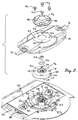
- the rotary cutter bed 10 illustrated in Fig. 1 has a series of individual cutter assemblies 12 that are essentially identical to one another.
- each assembly 12 includes an elliptical-shaped disc 14 that rotates at relatively high speeds about an upright axis and which carries a pair of flail-type cutter blades 16 at opposite ends thereof for impacting and severing standing crop materials as the disc rotates.
- Cutter assemblies 12 are timed relative to one another so that blades 16 of adjacent assemblies do not strike one another, even though their paths of travel overlap.
- each cutter assembly 12 further includes an upright, rotatable spindle 18 that defines the axis of rotation of disc 14.
- Spindle 18 is journaled by a bearing assembly 20 that is captured within an upright bore 22 in the central hub 24 of a stationary bearing housing 26.
- gear case 32 is comprised of a series of interconnected modules, but this construction can vary without affecting the principles of the present invention.
- spindle 18 is driven by an integrally joined spur gear 34 within the open compartment 36 of gear case 32 below hole 30.
- Spur gear 34 has a pair of idlers 38 (only one being shown) engaged therewith on opposite sides of spindle 18 for the purpose of receiving driving power from an adjacent module and transferring it along the gear train to the next adjacent module.
- This type of gear train may also be utilized without affecting the principles of the present invention including, for example, utilizing shafts and intermeshing bevel gears within gear case 32.
- the axes of rotation of idlers 38 are slightly behind spindle 18 and are represented in Fig. 2 by the hexagonal sockets 40 and 42 associated with bearing assemblies for the idlers 38.
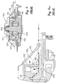
- spindle 18 includes a splined portion 44 as illustrated in Fig. that mates with the internally splined bore 46 of a generally conical cutter mounting member 48 so that cutter mounting member 48 rotates with spindle 18.
- Cutter mounting member 48 includes a central hub 50 through which bore 46 passes, the hub 50 being disposed in stacked relation to the hub 24 of stationary bearing housing 26.
- cutter mounting member 48 rotates relative to stationary bearing housing 26, which is secured to gear case 32 by a plurality of bolt assemblies 52 about the periphery of stationary bearing housing 26.
- a nut 54 and washer 56 on an uppermost externally threaded portion 58 of spindle 18 are utilized to secure cutter mounting member 48 in place on spindle 18.
- a horizontal, annular, flat flange 60 Projecting radially outwardly from hub 50 of cutter mounting member 48 is a horizontal, annular, flat flange 60.
- annular skirt 62 is affixed thereto and extends downwardly and outwardly therefrom.
- the outermost and lowermost extremity of skirt 62 defines a peripheral edge 64 of cutter mounting member 48.
- Skirt 62 thus presents a radially outer face 66 of cutter mounting member 48 that slopes upwardly and inwardly from peripheral edge 64, giving cutter mounting member 48 its overall conical appearance as illustrated in Fig. 2 .
- Due to the skirted construction of cutter mounting member 48, the underside of flange 60 and radially inside of skirt 62 define an annular void region 68 above stationary bearing housing 26.
- Stationary bearing housing 26 also is provided with an annular, generally flat, horizontally extending flange 70 that projects outwardly from hub 24.
- annular rib 72 is defined in surrounding relationship to the peripheral edge 64 of cutter mounting member 48. Rib 72 projects upwardly beyond peripheral edge 64 and cooperates with the hub 24 to define a continuous, annular recess 74 in the top face of flange 70 that receives skirt edge 64.
- rib 72 is generally triangular in cross-sectional configuration so as to present an outer, upwardly and inwardly sloping face 76.
- face 76 of rib 72 and face 66 of skirt 62 slope generally upwardly and inwardly in the same direction, although in the illustrated embodiment, face 76 of rib 72 has a slightly lower slope angle than face 66 of skirt 62 such that face 76 slopes generally toward face 66.
- rib 72 is a continuous rib about the periphery of cutter mounting member 48, although it is within the principles of the present invention to have such rib discontinuous as well.
- the upper surface of flange 60 of cutter mounting member 48 is provided with four drilled and tapped holes 78. Such holes 78 threadably receive four bolts 80 to detachably secure disc 14 to cutter mounting member 48. Corresponding holes 82 in disc 14 register with holes 78 in mounting cutter mounting member 48 to allow the shanks of bolts 80 to pass through disc 14 and into threaded engagement with cutter mounting member 48. A larger centrally disposed hole 84 in disc 14 receives the upper portion of hub 50 when disc 14 is in place on cutter mounting member 48. A domed cap 86 may be fastened to disc 14 in overlying relationship to large hole 84 and the upper end of spindle 18 and nut 54 for covering such structures. Cap 86 is provided with four bolt holes 88 that align with holes 78 and 82 so that bolts 80 may be utilized to secure cap 86 in place.
- cutter mounting member 48 it is not necessary to remove cutter mounting member 48 because materials should not be accumulating within the inner void region 68. Thus, there is no need to loosen and remove the main nut 54 on spindle 18 and lift off cutter mounting member 48. This is a great time-saver and also avoids the risk of failing to re-establish proper timing relationship in the cutter assembly when cutter mounting member 48 is replaced on spindle 18 and nut 54 is tightened down.
- Figs. 4 and 4a illustrate a prior art construction which allows debris and other foreign materials to enter deeply into the cutter assembly and cause damage to the bearing assembly or premature failure thereof.
- the prior art cutter assembly is designated by the numeral 100 and includes many of the same components as cutter assembly 12, but in different configuration.
- the spindle 102 is journaled by a bearing assembly 104 that is in turn retained by a bearing housing 106 secured to the gear case 108.
- a cutter mounting member 110 is secured to spindle 102 for rotation therewith relative to bearing housing 106, and a disc 112 is secured to cutter mounting member 110 for rotation therewith.
- Cutter mounting member 110 has a radially outermost, downwardly projecting, annular skirt 114 that presents a lowermost peripheral edge 116 spaced only a short distance above bearing housing 106 so as to provide running clearance.
- Skirt 114 has a vertical, non-tapering outer face 118.
- An inner annular void region 120 is defined above the flange of bearing housing 106 and inboard of skirt 114, while an outer annual void region 122 is defined under the outer portion of disc 112 and outboard of skirt 118 above bearing housing flange 106.
- the foreign materials have no opportunity to enter the inner void region 68. Instead, the most that can happen is that they are guided upwardly by the sloping outer face 66 of cutter mounting member 48 to migrate toward the top corner of the outer void region 92, where they accumulate beneath the underside of disc 14. Such materials can then be quickly and easily removed by simply pulling off the disc 14 and removing the materials.
Landscapes
- Life Sciences & Earth Sciences (AREA)
- Environmental Sciences (AREA)
- Harvester Elements (AREA)
Claims (7)
- Ensemble de coupe tournant (12) comportant une broche verticale pouvant tourner (18) ;
un boîtier de palier fixe (26) comportant un alésage vertical (22) ;
un ensemble de palier (20) disposé à l'intérieur dudit alésage et assurant le montage en palier de ladite broche afin d'assurer une rotation autour d'un axe vertical ; et
un élément de montage de couteau (48) fixé sur ladite broche au-dessus du boîtier de palier fixe afin de tourner avec la broche par rapport audit boîtier de palier fixe,
ledit élément de montage de couteau comportant un bord périphérique inférieur (64) disposé radialement à l'extérieur,
ledit boîtier de palier fixe comportant une nervure annulaire (72) en saillie vers le haut au-delà dudit bord périphérique inférieur (64), caractérisé en ce que la nervure annulaire (72) entoure ledit bord périphérique inférieur de l'élément de montage de couteau afin d'inhiber la migration de matières étrangères dans l'ensemble de palier à partir de l'extérieur de l'ensemble de coupe, et dans lequel ledit élément de montage de couteau comporte une face radialement à l'extérieur (66) qui est inclinée vers le haut et vers l'intérieur à partir dudit bord périphérique inférieur. - Ensemble de coupe tournant selon la revendication 1,
ladite nervure (72) étant continue sur la circonférence. - Ensemble de coupe tournant selon l'une quelconque des revendications 1 ou 2,
ladite nervure comportant une face externe radialement inclinée vers le haut et vers l'intérieur (76). - Ensemble de coupe tournant selon la revendication 3,
ladite face externe de la nervure étant inclinée vers le haut, vers ladite face externe de l'élément de montage de couteau. - Ensemble de coupe tournant selon l'une quelconque des revendications précédentes,
ledit élément de montage de couteau comportant une collerette annulaire s'étendant radialement vers l'extérieur et vers le bas,
ladite face annulaire externe (62) et ledit bord périphérique inférieur de l'élément de montage de couteau étant sur ladite collerette. - Ensemble de coupe tournant selon la revendication 5,
ledit boîtier de palier fixe comportant un moyeu central (24) présentant une extrémité supérieure,
ledit moyeu et ladite nervure coopérant afin de définir une cavité annulaire (74) au-dessous de ladite extrémité supérieure du moyeu et à l'intérieur duquel tourne ledit bord périphérique inférieur de la collerette. - Ensemble de coupe tournant selon la revendication 6,
ladite nervure étant continue sur la circonférence.
Applications Claiming Priority (2)
| Application Number | Priority Date | Filing Date | Title |
|---|---|---|---|
| US12/140,986 US7536846B1 (en) | 2008-06-17 | 2008-06-17 | Debris diverter for a rotary cutter |
| PCT/IB2009/005844 WO2009153636A1 (fr) | 2008-06-17 | 2009-06-04 | Déflecteur de débris pour coupeuse rotative |
Publications (2)
| Publication Number | Publication Date |
|---|---|
| EP2328397A1 EP2328397A1 (fr) | 2011-06-08 |
| EP2328397B1 true EP2328397B1 (fr) | 2016-04-06 |
Family
ID=40652003
Family Applications (1)
| Application Number | Title | Priority Date | Filing Date |
|---|---|---|---|
| EP09766178.9A Active EP2328397B1 (fr) | 2008-06-17 | 2009-06-04 | Déflecteur de débris pour coupeuse rotative |
Country Status (4)
| Country | Link |
|---|---|
| US (1) | US7536846B1 (fr) |
| EP (1) | EP2328397B1 (fr) |
| CA (1) | CA2726115C (fr) |
| WO (1) | WO2009153636A1 (fr) |
Families Citing this family (11)
| Publication number | Priority date | Publication date | Assignee | Title |
|---|---|---|---|---|
| IT1401699B1 (it) * | 2010-09-13 | 2013-08-02 | Feraboli S P A | Gruppo falciante a dischi, particolarmente per macchine agricole del tipo falciatrici, falciacondizionatrici o simili, ad elevata sicurezza di impiego. |
| US9795080B2 (en) | 2012-04-03 | 2017-10-24 | Cnh Industrial America Llc | Disc mower cutterbar shroud |
| US9717175B2 (en) * | 2014-04-29 | 2017-08-01 | Cnh Industrial America Llc | Rock guard for quick change knives on a disc mower |
| EP3120682B1 (fr) * | 2015-07-20 | 2018-02-28 | Kverneland Group Kerteminde AS | Unité de coupe rotative |
| US10412884B2 (en) * | 2016-03-04 | 2019-09-17 | Deere & Company | Cutterbar module structure |
| US10412885B2 (en) * | 2016-03-04 | 2019-09-17 | Deere & Company | Rotary cutterbar module end cap |
| US10412883B2 (en) * | 2016-03-04 | 2019-09-17 | Deere & Company | Joint for rotary cutterbar |
| US10412886B2 (en) * | 2016-03-04 | 2019-09-17 | Deere & Company | Debris diverter for rotary cutterbar |
| FR3052016B1 (fr) * | 2016-06-01 | 2018-06-15 | Kuhn S.A. | Faucheuse a barre de coupe a disques rotatifs a couteaux |
| US10842075B2 (en) * | 2018-07-10 | 2020-11-24 | Macdon Industries | Crop convergence system for rotary mower |
| US12453307B2 (en) * | 2022-09-26 | 2025-10-28 | Deere & Company | Rotary cutter-bar with blade sensor |
Family Cites Families (11)
| Publication number | Priority date | Publication date | Assignee | Title |
|---|---|---|---|---|
| NL6506452A (fr) | 1965-05-20 | 1966-11-21 | ||
| NL8201507A (nl) * | 1973-04-27 | 1982-08-02 | Lely Nv C Van Der | Maaimachine. |
| FR2474811A1 (fr) * | 1980-02-04 | 1981-08-07 | Kuhn Sa | Barre de coupe perfectionnee |
| NL8101239A (nl) | 1981-03-13 | 1982-10-01 | Multinorm Bv | Maaiinrichting met gedeelde maaibalk. |
| NL8203461A (nl) * | 1982-09-06 | 1984-04-02 | Lely Nv C Van Der | Maaiinrichting voor landbouwdoeleinden. |
| US4838014A (en) * | 1986-03-31 | 1989-06-13 | Ford New Holland, Inc. | Disc cutter rotor assembly |
| US5012635A (en) | 1990-06-01 | 1991-05-07 | Deere & Company | Modular cutterbar for rotary mower |
| US4986060A (en) | 1990-06-01 | 1991-01-22 | Deere & Company | Modular rotary mower cutterbar incorporating unique idler gear mounting |
| US5784866A (en) * | 1996-06-25 | 1998-07-28 | New Holland North America, Inc. | Disc cutterbar for agricultural implements |
| US5715662A (en) | 1995-11-17 | 1998-02-10 | Deere & Company | Drive shear device for rotary cutter unit |
| US5964079A (en) | 1998-03-04 | 1999-10-12 | Deere & Company | Rotary cutterbar housing modules having angled sides |
-
2008
- 2008-06-17 US US12/140,986 patent/US7536846B1/en active Active
-
2009
- 2009-06-04 CA CA2726115A patent/CA2726115C/fr active Active
- 2009-06-04 EP EP09766178.9A patent/EP2328397B1/fr active Active
- 2009-06-04 WO PCT/IB2009/005844 patent/WO2009153636A1/fr not_active Ceased
Also Published As
| Publication number | Publication date |
|---|---|
| CA2726115A1 (fr) | 2009-12-23 |
| WO2009153636A1 (fr) | 2009-12-23 |
| EP2328397A1 (fr) | 2011-06-08 |
| US7536846B1 (en) | 2009-05-26 |
| CA2726115C (fr) | 2016-02-16 |
Similar Documents
| Publication | Publication Date | Title |
|---|---|---|
| EP2328397B1 (fr) | Déflecteur de débris pour coupeuse rotative | |
| CA2189786C (fr) | Dispositif de coupe monte sur un arbre d'entrainement et destine a une barre de coupe rotative | |
| CA2707080C (fr) | Barre de coupe rotative modulaire | |
| US7973654B2 (en) | Cutterbar failure detection system and method | |
| US7988380B2 (en) | Seal hub for protection of seal and bearing from metal fragments due to shearing of a shock device | |
| HU192340B (en) | Harvester-mower | |
| US6718745B1 (en) | Disc shear hub | |
| JPH02177814A (ja) | 切断具の装着法が改良された草刈機 | |
| EP2520149B1 (fr) | Dispositif de tonte | |
| US6675563B1 (en) | Disc cutterbar shear protection | |
| US5845468A (en) | Rotary mower cutter disc having replaceable knife mount shield | |
| JPH01273510A (ja) | カッターバー | |
| US5749208A (en) | Mowing apparatus | |
| ITMI20101660A1 (it) | Gruppo falciante a dischi, particolarmente per macchine agricole del tipo falciatrici, falciacondizionatrici o simili, ad elevata sicurezza di impiego. | |
| US20060021316A1 (en) | Disc cutterbar shear device | |
| CN105917855A (zh) | 一种割断喂入装置 | |
| CA2990512C (fr) | Unite de coupe rotative | |
| US20120047752A1 (en) | Mower Blade Attachment | |
| CN105052432A (zh) | 切草器 | |
| CN109429702B (zh) | 一种甘蔗根切装置 | |
| CN101822151B (zh) | 一种与联合收割机匹配的通用式秸秆切碎机 | |
| KR20130141774A (ko) | 예초기 | |
| FI131707B1 (sv) | Drivenhet för tallriksslåttermaskin | |
| EP3120682B1 (fr) | Unité de coupe rotative | |
| CZ28522U1 (cs) | Žací ústrojí jednorotorového žacího stroje |
Legal Events
| Date | Code | Title | Description |
|---|---|---|---|
| PUAI | Public reference made under article 153(3) epc to a published international application that has entered the european phase |
Free format text: ORIGINAL CODE: 0009012 |
|
| 17P | Request for examination filed |
Effective date: 20110117 |
|
| AK | Designated contracting states |
Kind code of ref document: A1 Designated state(s): AT BE BG CH CY CZ DE DK EE ES FI FR GB GR HR HU IE IS IT LI LT LU LV MC MK MT NL NO PL PT RO SE SI SK TR |
|
| AX | Request for extension of the european patent |
Extension state: AL BA RS |
|
| DAX | Request for extension of the european patent (deleted) | ||
| REG | Reference to a national code |
Ref country code: DE Ref legal event code: R079 Ref document number: 602009037528 Country of ref document: DE Free format text: PREVIOUS MAIN CLASS: A01D0034660000 Ipc: A01D0075180000 |
|
| GRAP | Despatch of communication of intention to grant a patent |
Free format text: ORIGINAL CODE: EPIDOSNIGR1 |
|
| RIC1 | Information provided on ipc code assigned before grant |
Ipc: A01D 75/18 20060101AFI20151028BHEP Ipc: A01D 34/66 20060101ALI20151028BHEP |
|
| INTG | Intention to grant announced |
Effective date: 20151124 |
|
| GRAS | Grant fee paid |
Free format text: ORIGINAL CODE: EPIDOSNIGR3 |
|
| GRAA | (expected) grant |
Free format text: ORIGINAL CODE: 0009210 |
|
| AK | Designated contracting states |
Kind code of ref document: B1 Designated state(s): AT BE BG CH CY CZ DE DK EE ES FI FR GB GR HR HU IE IS IT LI LT LU LV MC MK MT NL NO PL PT RO SE SI SK TR |
|
| REG | Reference to a national code |
Ref country code: GB Ref legal event code: FG4D |
|
| REG | Reference to a national code |
Ref country code: AT Ref legal event code: REF Ref document number: 786650 Country of ref document: AT Kind code of ref document: T Effective date: 20160415 Ref country code: CH Ref legal event code: EP |
|
| REG | Reference to a national code |
Ref country code: IE Ref legal event code: FG4D |
|
| REG | Reference to a national code |
Ref country code: DE Ref legal event code: R096 Ref document number: 602009037528 Country of ref document: DE |
|
| REG | Reference to a national code |
Ref country code: FR Ref legal event code: PLFP Year of fee payment: 8 |
|
| REG | Reference to a national code |
Ref country code: LT Ref legal event code: MG4D Ref country code: NL Ref legal event code: MP Effective date: 20160406 |
|
| REG | Reference to a national code |
Ref country code: AT Ref legal event code: MK05 Ref document number: 786650 Country of ref document: AT Kind code of ref document: T Effective date: 20160406 |
|
| PG25 | Lapsed in a contracting state [announced via postgrant information from national office to epo] |
Ref country code: NL Free format text: LAPSE BECAUSE OF FAILURE TO SUBMIT A TRANSLATION OF THE DESCRIPTION OR TO PAY THE FEE WITHIN THE PRESCRIBED TIME-LIMIT Effective date: 20160406 |
|
| PG25 | Lapsed in a contracting state [announced via postgrant information from national office to epo] |
Ref country code: LT Free format text: LAPSE BECAUSE OF FAILURE TO SUBMIT A TRANSLATION OF THE DESCRIPTION OR TO PAY THE FEE WITHIN THE PRESCRIBED TIME-LIMIT Effective date: 20160406 Ref country code: IS Free format text: LAPSE BECAUSE OF FAILURE TO SUBMIT A TRANSLATION OF THE DESCRIPTION OR TO PAY THE FEE WITHIN THE PRESCRIBED TIME-LIMIT Effective date: 20160806 Ref country code: PL Free format text: LAPSE BECAUSE OF FAILURE TO SUBMIT A TRANSLATION OF THE DESCRIPTION OR TO PAY THE FEE WITHIN THE PRESCRIBED TIME-LIMIT Effective date: 20160406 Ref country code: FI Free format text: LAPSE BECAUSE OF FAILURE TO SUBMIT A TRANSLATION OF THE DESCRIPTION OR TO PAY THE FEE WITHIN THE PRESCRIBED TIME-LIMIT Effective date: 20160406 Ref country code: NO Free format text: LAPSE BECAUSE OF FAILURE TO SUBMIT A TRANSLATION OF THE DESCRIPTION OR TO PAY THE FEE WITHIN THE PRESCRIBED TIME-LIMIT Effective date: 20160706 |
|
| PG25 | Lapsed in a contracting state [announced via postgrant information from national office to epo] |
Ref country code: PT Free format text: LAPSE BECAUSE OF FAILURE TO SUBMIT A TRANSLATION OF THE DESCRIPTION OR TO PAY THE FEE WITHIN THE PRESCRIBED TIME-LIMIT Effective date: 20160808 Ref country code: ES Free format text: LAPSE BECAUSE OF FAILURE TO SUBMIT A TRANSLATION OF THE DESCRIPTION OR TO PAY THE FEE WITHIN THE PRESCRIBED TIME-LIMIT Effective date: 20160406 Ref country code: AT Free format text: LAPSE BECAUSE OF FAILURE TO SUBMIT A TRANSLATION OF THE DESCRIPTION OR TO PAY THE FEE WITHIN THE PRESCRIBED TIME-LIMIT Effective date: 20160406 Ref country code: HR Free format text: LAPSE BECAUSE OF FAILURE TO SUBMIT A TRANSLATION OF THE DESCRIPTION OR TO PAY THE FEE WITHIN THE PRESCRIBED TIME-LIMIT Effective date: 20160406 Ref country code: GR Free format text: LAPSE BECAUSE OF FAILURE TO SUBMIT A TRANSLATION OF THE DESCRIPTION OR TO PAY THE FEE WITHIN THE PRESCRIBED TIME-LIMIT Effective date: 20160707 Ref country code: SE Free format text: LAPSE BECAUSE OF FAILURE TO SUBMIT A TRANSLATION OF THE DESCRIPTION OR TO PAY THE FEE WITHIN THE PRESCRIBED TIME-LIMIT Effective date: 20160406 Ref country code: LV Free format text: LAPSE BECAUSE OF FAILURE TO SUBMIT A TRANSLATION OF THE DESCRIPTION OR TO PAY THE FEE WITHIN THE PRESCRIBED TIME-LIMIT Effective date: 20160406 |
|
| PG25 | Lapsed in a contracting state [announced via postgrant information from national office to epo] |
Ref country code: BE Free format text: LAPSE BECAUSE OF FAILURE TO SUBMIT A TRANSLATION OF THE DESCRIPTION OR TO PAY THE FEE WITHIN THE PRESCRIBED TIME-LIMIT Effective date: 20160406 |
|
| REG | Reference to a national code |
Ref country code: DE Ref legal event code: R097 Ref document number: 602009037528 Country of ref document: DE |
|
| PG25 | Lapsed in a contracting state [announced via postgrant information from national office to epo] |
Ref country code: CZ Free format text: LAPSE BECAUSE OF FAILURE TO SUBMIT A TRANSLATION OF THE DESCRIPTION OR TO PAY THE FEE WITHIN THE PRESCRIBED TIME-LIMIT Effective date: 20160406 Ref country code: DK Free format text: LAPSE BECAUSE OF FAILURE TO SUBMIT A TRANSLATION OF THE DESCRIPTION OR TO PAY THE FEE WITHIN THE PRESCRIBED TIME-LIMIT Effective date: 20160406 Ref country code: SK Free format text: LAPSE BECAUSE OF FAILURE TO SUBMIT A TRANSLATION OF THE DESCRIPTION OR TO PAY THE FEE WITHIN THE PRESCRIBED TIME-LIMIT Effective date: 20160406 Ref country code: MC Free format text: LAPSE BECAUSE OF FAILURE TO SUBMIT A TRANSLATION OF THE DESCRIPTION OR TO PAY THE FEE WITHIN THE PRESCRIBED TIME-LIMIT Effective date: 20160406 Ref country code: EE Free format text: LAPSE BECAUSE OF FAILURE TO SUBMIT A TRANSLATION OF THE DESCRIPTION OR TO PAY THE FEE WITHIN THE PRESCRIBED TIME-LIMIT Effective date: 20160406 Ref country code: RO Free format text: LAPSE BECAUSE OF FAILURE TO SUBMIT A TRANSLATION OF THE DESCRIPTION OR TO PAY THE FEE WITHIN THE PRESCRIBED TIME-LIMIT Effective date: 20160406 |
|
| REG | Reference to a national code |
Ref country code: CH Ref legal event code: PL |
|
| PLBE | No opposition filed within time limit |
Free format text: ORIGINAL CODE: 0009261 |
|
| STAA | Information on the status of an ep patent application or granted ep patent |
Free format text: STATUS: NO OPPOSITION FILED WITHIN TIME LIMIT |
|
| 26N | No opposition filed |
Effective date: 20170110 |
|
| GBPC | Gb: european patent ceased through non-payment of renewal fee |
Effective date: 20160706 |
|
| REG | Reference to a national code |
Ref country code: IE Ref legal event code: MM4A |
|
| PG25 | Lapsed in a contracting state [announced via postgrant information from national office to epo] |
Ref country code: CH Free format text: LAPSE BECAUSE OF NON-PAYMENT OF DUE FEES Effective date: 20160630 Ref country code: LI Free format text: LAPSE BECAUSE OF NON-PAYMENT OF DUE FEES Effective date: 20160630 |
|
| PG25 | Lapsed in a contracting state [announced via postgrant information from national office to epo] |
Ref country code: SI Free format text: LAPSE BECAUSE OF FAILURE TO SUBMIT A TRANSLATION OF THE DESCRIPTION OR TO PAY THE FEE WITHIN THE PRESCRIBED TIME-LIMIT Effective date: 20160406 Ref country code: IE Free format text: LAPSE BECAUSE OF NON-PAYMENT OF DUE FEES Effective date: 20160604 Ref country code: GB Free format text: LAPSE BECAUSE OF NON-PAYMENT OF DUE FEES Effective date: 20160706 |
|
| REG | Reference to a national code |
Ref country code: FR Ref legal event code: PLFP Year of fee payment: 9 |
|
| PG25 | Lapsed in a contracting state [announced via postgrant information from national office to epo] |
Ref country code: HU Free format text: LAPSE BECAUSE OF FAILURE TO SUBMIT A TRANSLATION OF THE DESCRIPTION OR TO PAY THE FEE WITHIN THE PRESCRIBED TIME-LIMIT; INVALID AB INITIO Effective date: 20090604 Ref country code: CY Free format text: LAPSE BECAUSE OF FAILURE TO SUBMIT A TRANSLATION OF THE DESCRIPTION OR TO PAY THE FEE WITHIN THE PRESCRIBED TIME-LIMIT Effective date: 20160406 |
|
| REG | Reference to a national code |
Ref country code: FR Ref legal event code: PLFP Year of fee payment: 10 |
|
| PG25 | Lapsed in a contracting state [announced via postgrant information from national office to epo] |
Ref country code: MK Free format text: LAPSE BECAUSE OF FAILURE TO SUBMIT A TRANSLATION OF THE DESCRIPTION OR TO PAY THE FEE WITHIN THE PRESCRIBED TIME-LIMIT Effective date: 20160406 Ref country code: LU Free format text: LAPSE BECAUSE OF NON-PAYMENT OF DUE FEES Effective date: 20160604 Ref country code: TR Free format text: LAPSE BECAUSE OF FAILURE TO SUBMIT A TRANSLATION OF THE DESCRIPTION OR TO PAY THE FEE WITHIN THE PRESCRIBED TIME-LIMIT Effective date: 20160406 Ref country code: MT Free format text: LAPSE BECAUSE OF NON-PAYMENT OF DUE FEES Effective date: 20160630 |
|
| PG25 | Lapsed in a contracting state [announced via postgrant information from national office to epo] |
Ref country code: BG Free format text: LAPSE BECAUSE OF FAILURE TO SUBMIT A TRANSLATION OF THE DESCRIPTION OR TO PAY THE FEE WITHIN THE PRESCRIBED TIME-LIMIT Effective date: 20160406 |
|
| PGFP | Annual fee paid to national office [announced via postgrant information from national office to epo] |
Ref country code: IT Payment date: 20220628 Year of fee payment: 14 |
|
| P01 | Opt-out of the competence of the unified patent court (upc) registered |
Effective date: 20230518 |
|
| PG25 | Lapsed in a contracting state [announced via postgrant information from national office to epo] |
Ref country code: IT Free format text: LAPSE BECAUSE OF NON-PAYMENT OF DUE FEES Effective date: 20230604 |
|
| PGFP | Annual fee paid to national office [announced via postgrant information from national office to epo] |
Ref country code: DE Payment date: 20250618 Year of fee payment: 17 |
|
| PGFP | Annual fee paid to national office [announced via postgrant information from national office to epo] |
Ref country code: FR Payment date: 20250624 Year of fee payment: 17 |