EP2328397B1 - Debris diverter for a rotary cutter - Google Patents
Debris diverter for a rotary cutter Download PDFInfo
- Publication number
- EP2328397B1 EP2328397B1 EP09766178.9A EP09766178A EP2328397B1 EP 2328397 B1 EP2328397 B1 EP 2328397B1 EP 09766178 A EP09766178 A EP 09766178A EP 2328397 B1 EP2328397 B1 EP 2328397B1
- Authority
- EP
- European Patent Office
- Prior art keywords
- mounting member
- assembly
- cutter
- rib
- cutter mounting
- Prior art date
- Legal status (The legal status is an assumption and is not a legal conclusion. Google has not performed a legal analysis and makes no representation as to the accuracy of the status listed.)
- Active
Links
Images


Classifications
-
- A—HUMAN NECESSITIES
- A01—AGRICULTURE; FORESTRY; ANIMAL HUSBANDRY; HUNTING; TRAPPING; FISHING
- A01D—HARVESTING; MOWING
- A01D34/00—Mowers; Mowing apparatus of harvesters
- A01D34/01—Mowers; Mowing apparatus of harvesters characterised by features relating to the type of cutting apparatus
- A01D34/412—Mowers; Mowing apparatus of harvesters characterised by features relating to the type of cutting apparatus having rotating cutters
- A01D34/63—Mowers; Mowing apparatus of harvesters characterised by features relating to the type of cutting apparatus having rotating cutters having cutters rotating about a vertical axis
- A01D34/82—Other details
- A01D34/828—Safety devices
-
- A—HUMAN NECESSITIES
- A01—AGRICULTURE; FORESTRY; ANIMAL HUSBANDRY; HUNTING; TRAPPING; FISHING
- A01D—HARVESTING; MOWING
- A01D34/00—Mowers; Mowing apparatus of harvesters
- A01D34/01—Mowers; Mowing apparatus of harvesters characterised by features relating to the type of cutting apparatus
- A01D34/412—Mowers; Mowing apparatus of harvesters characterised by features relating to the type of cutting apparatus having rotating cutters
- A01D34/63—Mowers; Mowing apparatus of harvesters characterised by features relating to the type of cutting apparatus having rotating cutters having cutters rotating about a vertical axis
- A01D34/64—Mowers; Mowing apparatus of harvesters characterised by features relating to the type of cutting apparatus having rotating cutters having cutters rotating about a vertical axis mounted on a vehicle, e.g. a tractor, or drawn by an animal or a vehicle
- A01D34/66—Mowers; Mowing apparatus of harvesters characterised by features relating to the type of cutting apparatus having rotating cutters having cutters rotating about a vertical axis mounted on a vehicle, e.g. a tractor, or drawn by an animal or a vehicle with two or more cutters
- A01D34/664—Disc cutter bars
-
- A—HUMAN NECESSITIES
- A01—AGRICULTURE; FORESTRY; ANIMAL HUSBANDRY; HUNTING; TRAPPING; FISHING
- A01D—HARVESTING; MOWING
- A01D75/00—Accessories for harvesters or mowers
- A01D75/18—Safety devices for parts of the machines
- A01D75/187—Removing foreign objects
Definitions
- the present invention relates to the field of rotary cutters such as the type used in farm equipment for mowing standing crop materials. More particularly, it relates to a way of inhibiting the migration of stringy materials and foreign matter deeply into the interior of such cutter assemblies where they can cause damage and premature component failure.
- High speed rotary cutters are well known in the art.
- one nagging problem with such cutters is that foreign materials such as baling twine, wire or stringy crop materials can sometimes migrate into the bearing cavity of the cutters and wrap around the rotating spindle. This can cause damage to seals associated with the bearings and lead to premature bearing failure. Even if the materials do not reach the bearing cavity, they can still become wrapped tightly under the cutter mounting member of the assembly and build up to such a point that they generate an inordinate amount of heat, which can also result in premature bearing failure.
- EP-A-0,774,202 discloses a rotary cutter unit having a disk hub mounted to a shaft for rotational movement relative to a bearing housing.
- US-3,469,378 discloses a disc mower having a cutting disc carrying a downwardly directed collar which rotates in a circular groove of a stationary plate.
- an important object of the present invention is to provide a rotary cutter assembly that inhibits the migration of deleterious materials into the immediate vicinity of the bearing assembly of the unit. It is also an important object of the invention to provide a cutter design that encourages foreign materials that would otherwise migrate to the centre of the assembly to instead wrap around more exterior portions of the assembly in places less likely to cause damage and where they can be more easily removed.
- a rotary cutter assembly having an upright, rotatable spindle, a stationary bearing housing having an upright bore, a bearing assembly disposed within said bore and journaling said spindle for rotation about an upright axis; and a cutter mounting member secured to said spindle above the stationary bearing housing for rotation with the spindle relative to said stationary bearing housing, said cutter mounting member having a radially outwardly disposed lower peripheral edge, said stationary bearing housing having an annular rib projecting upwardly beyond said lower peripheral edge, characterised in that the annular rib surrounds said lower peripheral edge of the cutter mounting member to inhibit the migration of foreign materials into the bearing assembly from the exterior of the cutter assembly, and wherein said cutter mounting member has a radially outer face that slopes upwardly and inwardly from said lower peripheral edge.
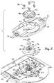
- the rotary cutter bed 10 illustrated in Fig. 1 has a series of individual cutter assemblies 12 that are essentially identical to one another.
- each assembly 12 includes an elliptical-shaped disc 14 that rotates at relatively high speeds about an upright axis and which carries a pair of flail-type cutter blades 16 at opposite ends thereof for impacting and severing standing crop materials as the disc rotates.
- Cutter assemblies 12 are timed relative to one another so that blades 16 of adjacent assemblies do not strike one another, even though their paths of travel overlap.
- each cutter assembly 12 further includes an upright, rotatable spindle 18 that defines the axis of rotation of disc 14.
- Spindle 18 is journaled by a bearing assembly 20 that is captured within an upright bore 22 in the central hub 24 of a stationary bearing housing 26.
- gear case 32 is comprised of a series of interconnected modules, but this construction can vary without affecting the principles of the present invention.
- spindle 18 is driven by an integrally joined spur gear 34 within the open compartment 36 of gear case 32 below hole 30.
- Spur gear 34 has a pair of idlers 38 (only one being shown) engaged therewith on opposite sides of spindle 18 for the purpose of receiving driving power from an adjacent module and transferring it along the gear train to the next adjacent module.
- This type of gear train may also be utilized without affecting the principles of the present invention including, for example, utilizing shafts and intermeshing bevel gears within gear case 32.
- the axes of rotation of idlers 38 are slightly behind spindle 18 and are represented in Fig. 2 by the hexagonal sockets 40 and 42 associated with bearing assemblies for the idlers 38.
- spindle 18 includes a splined portion 44 as illustrated in Fig. that mates with the internally splined bore 46 of a generally conical cutter mounting member 48 so that cutter mounting member 48 rotates with spindle 18.
- Cutter mounting member 48 includes a central hub 50 through which bore 46 passes, the hub 50 being disposed in stacked relation to the hub 24 of stationary bearing housing 26.
- cutter mounting member 48 rotates relative to stationary bearing housing 26, which is secured to gear case 32 by a plurality of bolt assemblies 52 about the periphery of stationary bearing housing 26.
- a nut 54 and washer 56 on an uppermost externally threaded portion 58 of spindle 18 are utilized to secure cutter mounting member 48 in place on spindle 18.
- a horizontal, annular, flat flange 60 Projecting radially outwardly from hub 50 of cutter mounting member 48 is a horizontal, annular, flat flange 60.
- annular skirt 62 is affixed thereto and extends downwardly and outwardly therefrom.
- the outermost and lowermost extremity of skirt 62 defines a peripheral edge 64 of cutter mounting member 48.
- Skirt 62 thus presents a radially outer face 66 of cutter mounting member 48 that slopes upwardly and inwardly from peripheral edge 64, giving cutter mounting member 48 its overall conical appearance as illustrated in Fig. 2 .
- Due to the skirted construction of cutter mounting member 48, the underside of flange 60 and radially inside of skirt 62 define an annular void region 68 above stationary bearing housing 26.
- Stationary bearing housing 26 also is provided with an annular, generally flat, horizontally extending flange 70 that projects outwardly from hub 24.
- annular rib 72 is defined in surrounding relationship to the peripheral edge 64 of cutter mounting member 48. Rib 72 projects upwardly beyond peripheral edge 64 and cooperates with the hub 24 to define a continuous, annular recess 74 in the top face of flange 70 that receives skirt edge 64.
- rib 72 is generally triangular in cross-sectional configuration so as to present an outer, upwardly and inwardly sloping face 76.
- face 76 of rib 72 and face 66 of skirt 62 slope generally upwardly and inwardly in the same direction, although in the illustrated embodiment, face 76 of rib 72 has a slightly lower slope angle than face 66 of skirt 62 such that face 76 slopes generally toward face 66.
- rib 72 is a continuous rib about the periphery of cutter mounting member 48, although it is within the principles of the present invention to have such rib discontinuous as well.
- the upper surface of flange 60 of cutter mounting member 48 is provided with four drilled and tapped holes 78. Such holes 78 threadably receive four bolts 80 to detachably secure disc 14 to cutter mounting member 48. Corresponding holes 82 in disc 14 register with holes 78 in mounting cutter mounting member 48 to allow the shanks of bolts 80 to pass through disc 14 and into threaded engagement with cutter mounting member 48. A larger centrally disposed hole 84 in disc 14 receives the upper portion of hub 50 when disc 14 is in place on cutter mounting member 48. A domed cap 86 may be fastened to disc 14 in overlying relationship to large hole 84 and the upper end of spindle 18 and nut 54 for covering such structures. Cap 86 is provided with four bolt holes 88 that align with holes 78 and 82 so that bolts 80 may be utilized to secure cap 86 in place.
- cutter mounting member 48 it is not necessary to remove cutter mounting member 48 because materials should not be accumulating within the inner void region 68. Thus, there is no need to loosen and remove the main nut 54 on spindle 18 and lift off cutter mounting member 48. This is a great time-saver and also avoids the risk of failing to re-establish proper timing relationship in the cutter assembly when cutter mounting member 48 is replaced on spindle 18 and nut 54 is tightened down.
- Figs. 4 and 4a illustrate a prior art construction which allows debris and other foreign materials to enter deeply into the cutter assembly and cause damage to the bearing assembly or premature failure thereof.
- the prior art cutter assembly is designated by the numeral 100 and includes many of the same components as cutter assembly 12, but in different configuration.
- the spindle 102 is journaled by a bearing assembly 104 that is in turn retained by a bearing housing 106 secured to the gear case 108.
- a cutter mounting member 110 is secured to spindle 102 for rotation therewith relative to bearing housing 106, and a disc 112 is secured to cutter mounting member 110 for rotation therewith.
- Cutter mounting member 110 has a radially outermost, downwardly projecting, annular skirt 114 that presents a lowermost peripheral edge 116 spaced only a short distance above bearing housing 106 so as to provide running clearance.
- Skirt 114 has a vertical, non-tapering outer face 118.
- An inner annular void region 120 is defined above the flange of bearing housing 106 and inboard of skirt 114, while an outer annual void region 122 is defined under the outer portion of disc 112 and outboard of skirt 118 above bearing housing flange 106.
- the foreign materials have no opportunity to enter the inner void region 68. Instead, the most that can happen is that they are guided upwardly by the sloping outer face 66 of cutter mounting member 48 to migrate toward the top corner of the outer void region 92, where they accumulate beneath the underside of disc 14. Such materials can then be quickly and easily removed by simply pulling off the disc 14 and removing the materials.
Landscapes
- Life Sciences & Earth Sciences (AREA)
- Environmental Sciences (AREA)
- Harvester Elements (AREA)
Description
- The present invention relates to the field of rotary cutters such as the type used in farm equipment for mowing standing crop materials. More particularly, it relates to a way of inhibiting the migration of stringy materials and foreign matter deeply into the interior of such cutter assemblies where they can cause damage and premature component failure.
- High speed rotary cutters are well known in the art. However, one nagging problem with such cutters is that foreign materials such as baling twine, wire or stringy crop materials can sometimes migrate into the bearing cavity of the cutters and wrap around the rotating spindle. This can cause damage to seals associated with the bearings and lead to premature bearing failure. Even if the materials do not reach the bearing cavity, they can still become wrapped tightly under the cutter mounting member of the assembly and build up to such a point that they generate an inordinate amount of heat, which can also result in premature bearing failure.
-
EP-A-0,774,202 discloses a rotary cutter unit having a disk hub mounted to a shaft for rotational movement relative to a bearing housing.US-3,469,378 discloses a disc mower having a cutting disc carrying a downwardly directed collar which rotates in a circular groove of a stationary plate. - Accordingly, an important object of the present invention is to provide a rotary cutter assembly that inhibits the migration of deleterious materials into the immediate vicinity of the bearing assembly of the unit. It is also an important object of the invention to provide a cutter design that encourages foreign materials that would otherwise migrate to the centre of the assembly to instead wrap around more exterior portions of the assembly in places less likely to cause damage and where they can be more easily removed.
- Thus according to the present invention there is provided a rotary cutter assembly having an upright, rotatable spindle, a stationary bearing housing having an upright bore, a bearing assembly disposed within said bore and journaling said spindle for rotation about an upright axis; and a cutter mounting member secured to said spindle above the stationary bearing housing for rotation with the spindle relative to said stationary bearing housing, said cutter mounting member having a radially outwardly disposed lower peripheral edge, said stationary bearing housing having an annular rib projecting upwardly beyond said lower peripheral edge, characterised in that the annular rib surrounds said lower peripheral edge of the cutter mounting member to inhibit the migration of foreign materials into the bearing assembly from the exterior of the cutter assembly, and wherein said cutter mounting member has a radially outer face that slopes upwardly and inwardly from said lower peripheral edge.
- One embodiment of the present invention will now be described, by way of example only, with reference to the accompanying drawings in which:-
-
Figure 1 is a top front isometric view of a rotary cutter bed of the type typically utilized in connection with windrowers, mower-conditioners and other mowing equipment and which may incorporate the principles of the present invention; -
Fig. 2 is an enlarged, fragmentary, exploded isometric view of one of the rotary cutter assemblies of the cutter bed inFig. 1 , illustrating details of construction; -
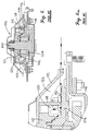
Fig. 3 is an enlarged, transverse cross-sectional view through one of the cutter assemblies taken substantially along line 3-3 ofFig. 1 ; -
Fig. 3a is a further enlarged, fragmentary view of the assembly inFig. 3 illustrating the manner in which a construction in accordance with the present invention inhibits the migration of foreign materials into the centre of the assembly; -
Fig. 4 is a transverse cross-sectional view of a prior art cutter assembly; and -
Fig. 4a is an enlarged, fragmentary cross-sectional view of the prior art assembly ofFig. 4 illustrating the way in which foreign materials migrate into the centre of the assembly. - The
rotary cutter bed 10 illustrated inFig. 1 has a series ofindividual cutter assemblies 12 that are essentially identical to one another. Among other things, eachassembly 12 includes an elliptical-shaped disc 14 that rotates at relatively high speeds about an upright axis and which carries a pair of flail-type cutter blades 16 at opposite ends thereof for impacting and severing standing crop materials as the disc rotates.Cutter assemblies 12 are timed relative to one another so thatblades 16 of adjacent assemblies do not strike one another, even though their paths of travel overlap. In the illustrated embodiment, the two outboard assemblies 12 at opposite ends ofbed 10 rotate in the same direction, i.e., generally toward the centre of the cutter bed, while the six remaininginboard assemblies 12 rotate in mutually opposite directions, i.e., in oppositely rotating pairs. As will be seen, this arrangement can obviously be varied without impacting the principles of the present invention.
As illustrated particularly inFigs. 2 ,3 and 3a , eachcutter assembly 12 further includes an upright,rotatable spindle 18 that defines the axis of rotation ofdisc 14. Spindle 18 is journaled by abearing assembly 20 that is captured within anupright bore 22 in thecentral hub 24 of a stationary bearinghousing 26. Stationary bearinghousing 26 rests upon an upwardly projectingrim 28 around ahole 30 in a generally flat,hollow gear case 32 of thecutter bed 10. In the illustrated embodiment,gear case 32 is comprised of a series of interconnected modules, but this construction can vary without affecting the principles of the present invention. - It will also be seen that in the illustrated embodiment,
spindle 18 is driven by an integrally joinedspur gear 34 within theopen compartment 36 ofgear case 32 belowhole 30.Spur gear 34 has a pair of idlers 38 (only one being shown) engaged therewith on opposite sides ofspindle 18 for the purpose of receiving driving power from an adjacent module and transferring it along the gear train to the next adjacent module. Numerous variations of this type of gear train may also be utilized without affecting the principles of the present invention including, for example, utilizing shafts and intermeshing bevel gears withingear case 32. The axes of rotation ofidlers 38 are slightly behindspindle 18 and are represented inFig. 2 by thehexagonal sockets idlers 38. - As illustrated in
Fig. 2 spindle 18 includes asplined portion 44 as illustrated in Fig. that mates with the internallysplined bore 46 of a generally conicalcutter mounting member 48 so thatcutter mounting member 48 rotates withspindle 18.Cutter mounting member 48 includes a central hub 50 through which bore 46 passes, the hub 50 being disposed in stacked relation to thehub 24 of stationary bearinghousing 26. Of course,cutter mounting member 48 rotates relative to stationary bearinghousing 26, which is secured togear case 32 by a plurality ofbolt assemblies 52 about the periphery of stationary bearinghousing 26. A nut 54 andwasher 56 on an uppermost externally threaded portion 58 ofspindle 18 are utilized to securecutter mounting member 48 in place onspindle 18. - Projecting radially outwardly from hub 50 of
cutter mounting member 48 is a horizontal, annular,flat flange 60. At the radially outermost extremity offlange 60, anannular skirt 62 is affixed thereto and extends downwardly and outwardly therefrom. The outermost and lowermost extremity ofskirt 62 defines aperipheral edge 64 ofcutter mounting member 48. Skirt 62 thus presents a radiallyouter face 66 ofcutter mounting member 48 that slopes upwardly and inwardly fromperipheral edge 64, givingcutter mounting member 48 its overall conical appearance as illustrated inFig. 2 . Due to the skirted construction ofcutter mounting member 48, the underside offlange 60 and radially inside ofskirt 62 define anannular void region 68 above stationary bearinghousing 26. - Stationary bearing
housing 26 also is provided with an annular, generally flat, horizontally extending flange 70 that projects outwardly fromhub 24. In the top surface of flange 70, an upstanding,annular rib 72 is defined in surrounding relationship to theperipheral edge 64 ofcutter mounting member 48.Rib 72 projects upwardly beyondperipheral edge 64 and cooperates with thehub 24 to define a continuous,annular recess 74 in the top face of flange 70 that receivesskirt edge 64. As illustrated particularly inFig. 3a ,rib 72 is generally triangular in cross-sectional configuration so as to present an outer, upwardly and inwardly slopingface 76. Thus,face 76 ofrib 72 andface 66 ofskirt 62 slope generally upwardly and inwardly in the same direction, although in the illustrated embodiment,face 76 ofrib 72 has a slightly lower slope angle thanface 66 ofskirt 62 such thatface 76 slopes generally towardface 66. In a most preferred embodiment of the invention,rib 72 is a continuous rib about the periphery ofcutter mounting member 48, although it is within the principles of the present invention to have such rib discontinuous as well. - The upper surface of
flange 60 ofcutter mounting member 48 is provided with four drilled and tappedholes 78.Such holes 78 threadably receive fourbolts 80 to detachablysecure disc 14 to cuttermounting member 48. Correspondingholes 82 indisc 14 register withholes 78 in mountingcutter mounting member 48 to allow the shanks ofbolts 80 to pass throughdisc 14 and into threaded engagement withcutter mounting member 48. A larger centrally disposedhole 84 indisc 14 receives the upper portion of hub 50 whendisc 14 is in place oncutter mounting member 48. Adomed cap 86 may be fastened to disc 14 in overlying relationship tolarge hole 84 and the upper end ofspindle 18 and nut 54 for covering such structures.Cap 86 is provided with fourbolt holes 88 that align withholes bolts 80 may be utilized to securecap 86 in place. - As illustrated especially in
Fig. 3a , whendisc 14 is rotating at high speeds, stringy crop materials, twine and other foreign matter can slip beneathdisc 14 as illustrated by thearrow 90 into an outerannular void region 92 defined between the underside ofdisc 14, the top of stationary bearinghousing 26 outboard ofcutter mounting member 48, andskirt 66 ofcutter mounting member 48. However, once the materials are within theouter void region 92, they can travel no further into the interior of the cutter assembly due to the barriers presented byrib 72 andskirt 62. Although the materials can wrap aroundskirt 62, such materials tend to migrate toward the portion of least diameter ofskirt 62, i.e., the top ofskirt 62adjacent flange 60, rather than work their way down and underperipheral edge 64 into theinner void region 68 closer to bearingassembly 20. There is no relative rotation betweencutter mounting member 48 anddisc 14; thus, materials that accumulate up in the corner betweencutter mounting member 48 anddisc 14 are not subjected to friction and heat buildup from high speed, relatively moving surfaces. This keeps bearingassembly 20 protected against the abrasive effects of the wrapping materials and prevents the build-up of excessive heat withininterior void region 68 which might otherwise adversely affect the useful life ofbearing assembly 20. - In the event it becomes necessary or desirable to remove accumulating materials from within the outer
void region 92, this can be readily accomplished by simply removingbolts 80, pulling offcap 86 anddiscs 14, and removing the accumulated materials from around the outside ofcutter mounting member 48. Thereafter,disc 14 and cover 86 are quickly and easily reinstalled andbolts 80 are tightened down to return the components to their normal operating conditions. - Note that it is not necessary to remove
cutter mounting member 48 because materials should not be accumulating within the innervoid region 68. Thus, there is no need to loosen and remove the main nut 54 onspindle 18 and lift offcutter mounting member 48. This is a great time-saver and also avoids the risk of failing to re-establish proper timing relationship in the cutter assembly whencutter mounting member 48 is replaced onspindle 18 and nut 54 is tightened down. -
Figs. 4 and 4a illustrate a prior art construction which allows debris and other foreign materials to enter deeply into the cutter assembly and cause damage to the bearing assembly or premature failure thereof. In these views, the prior art cutter assembly is designated by the numeral 100 and includes many of the same components ascutter assembly 12, but in different configuration. For example, in prior art cutter assembly 100, thespindle 102 is journaled by a bearingassembly 104 that is in turn retained by a bearinghousing 106 secured to thegear case 108. Acutter mounting member 110 is secured to spindle 102 for rotation therewith relative to bearinghousing 106, and adisc 112 is secured tocutter mounting member 110 for rotation therewith. -
Cutter mounting member 110 has a radially outermost, downwardly projecting,annular skirt 114 that presents a lowermostperipheral edge 116 spaced only a short distance above bearinghousing 106 so as to provide running clearance.Skirt 114 has a vertical, non-taperingouter face 118. An inner annularvoid region 120 is defined above the flange of bearinghousing 106 and inboard ofskirt 114, while an outer annualvoid region 122 is defined under the outer portion ofdisc 112 and outboard ofskirt 118 above bearinghousing flange 106. - In this prior art cutter assembly 100, foreign materials can slip under
discs 112 as illustrated by thearrow 124. Instead of remaining in the outervoid region 122, however, such materials have a tendency to work their way under theperipheral edge 116 ofskirt 118 and into the more sensitive innervoid region 120. Once within innervoid region 120, the materials can work their way through the interface betweencutter mounting member 110 and the hub of bearinghousing 106 to enter the bearing cavity where the bearingassembly 104 is located. Once in that region, the materials can destroy the seal the bearing assembly, allowing the grease to escape and causing the bearing to fail in that manner. Even if the materials do not fully find their way into the bearing cavity, their build-up within innervoid region 120 can result in the generation of excessive heat in that area caused by the frictional interengagement of rotatingcutter mounting member 110 and the trapped foreign matter, leading to premature bearing failure for that reason. This bearing failure then necessitates complete disassembly and rework of the cutter assembly. This is a very undesirable and frustrating circumstance, also causing significant loss of time during the repair and rebuild operations. - However, with the present invention as noted earlier, the foreign materials have no opportunity to enter the inner
void region 68. Instead, the most that can happen is that they are guided upwardly by the slopingouter face 66 ofcutter mounting member 48 to migrate toward the top corner of the outervoid region 92, where they accumulate beneath the underside ofdisc 14. Such materials can then be quickly and easily removed by simply pulling off thedisc 14 and removing the materials. - The inventor(s) hereby state(s) his/their intent to rely on the Doctrine of Equivalents to determine and assess the reasonably fair scope of his/their invention as pertains to any apparatus not materially departing from but outside the literal scope of the invention as set out in the following claims.
Claims (7)
- A rotary cutter assembly (12) having an upright, rotatable spindle (18);
a stationary bearing housing (26) having an upright bore (22);
a bearing assembly (20) disposed within said bore and journaling said spindle for rotation about an upright axis; and
a cutter mounting member (48) secured to said spindle above the stationary bearing housing for rotation with the spindle relative to said stationary bearing housing,
said cutter mounting member having a radially outwardly disposed lower peripheral edge (64),
said stationary bearing housing having an annular rib (72) projecting upwardly beyond said lower peripheral edge (64), characterised in that the annular rib (72) surrounds said lower peripheral edge of the cutter mounting member to inhibit the migration of foreign materials into the bearing assembly from the exterior of the cutter assembly, and wherein said cutter mounting member has a radially outer face (66) that slopes upwardly and inwardly from said lower peripheral edge. - A rotary cutter assembly as claimed in claim 1,
said rib (72) being circumferentially continuous. - A rotary cutter assembly as claimed in any one of claims 1 or 2,
said rib having an upwardly and inwardly sloping radially outer face (76). - A rotary cutter assembly as claimed in claim 3,
said outer face of the rib sloping upwardly toward said outer face of the cutter mounting member. - A rotary cutter assembly as claimed in any preceding claim,
said cutter mounting member having a radially outwardly and downwardly projecting, annular skirt (62),
said outer face and said lower peripheral edge of the cutter mounting member being on said skirt. - A rotary cutter assembly as claimed in claim 5,
said stationary bearing housing including a central hub (24) having an upper end,
said hub and said rib cooperating to define an annular recess (74) below said upper end of the hub and within which said lower peripheral edge of the skirt rotates. - A rotary cutter assembly as claimed in claim 6,
said rib being circumferentially continuous.
Applications Claiming Priority (2)
| Application Number | Priority Date | Filing Date | Title |
|---|---|---|---|
| US12/140,986 US7536846B1 (en) | 2008-06-17 | 2008-06-17 | Debris diverter for a rotary cutter |
| PCT/IB2009/005844 WO2009153636A1 (en) | 2008-06-17 | 2009-06-04 | Debris diverter for a rotary cutter |
Publications (2)
| Publication Number | Publication Date |
|---|---|
| EP2328397A1 EP2328397A1 (en) | 2011-06-08 |
| EP2328397B1 true EP2328397B1 (en) | 2016-04-06 |
Family
ID=40652003
Family Applications (1)
| Application Number | Title | Priority Date | Filing Date |
|---|---|---|---|
| EP09766178.9A Active EP2328397B1 (en) | 2008-06-17 | 2009-06-04 | Debris diverter for a rotary cutter |
Country Status (4)
| Country | Link |
|---|---|
| US (1) | US7536846B1 (en) |
| EP (1) | EP2328397B1 (en) |
| CA (1) | CA2726115C (en) |
| WO (1) | WO2009153636A1 (en) |
Families Citing this family (11)
| Publication number | Priority date | Publication date | Assignee | Title |
|---|---|---|---|---|
| IT1401699B1 (en) * | 2010-09-13 | 2013-08-02 | Feraboli S P A | MOWER WITH DISC MOWERS, PARTICULARLY FOR AGRICULTURAL MACHINES OF THE MOWERS, MOWERS OR SIMILAR TYPE, WITH HIGH SAFETY OF USE. |
| US9795080B2 (en) | 2012-04-03 | 2017-10-24 | Cnh Industrial America Llc | Disc mower cutterbar shroud |
| US9717175B2 (en) * | 2014-04-29 | 2017-08-01 | Cnh Industrial America Llc | Rock guard for quick change knives on a disc mower |
| EP3120682B1 (en) * | 2015-07-20 | 2018-02-28 | Kverneland Group Kerteminde AS | Rotary cutter unit |
| US10412884B2 (en) * | 2016-03-04 | 2019-09-17 | Deere & Company | Cutterbar module structure |
| US10412885B2 (en) * | 2016-03-04 | 2019-09-17 | Deere & Company | Rotary cutterbar module end cap |
| US10412883B2 (en) * | 2016-03-04 | 2019-09-17 | Deere & Company | Joint for rotary cutterbar |
| US10412886B2 (en) * | 2016-03-04 | 2019-09-17 | Deere & Company | Debris diverter for rotary cutterbar |
| FR3052016B1 (en) * | 2016-06-01 | 2018-06-15 | Kuhn S.A. | ROTATING DISC CUTTING MOWER WITH KNIFE |
| US10842075B2 (en) * | 2018-07-10 | 2020-11-24 | Macdon Industries | Crop convergence system for rotary mower |
| US12453307B2 (en) * | 2022-09-26 | 2025-10-28 | Deere & Company | Rotary cutter-bar with blade sensor |
Family Cites Families (11)
| Publication number | Priority date | Publication date | Assignee | Title |
|---|---|---|---|---|
| NL6506452A (en) | 1965-05-20 | 1966-11-21 | ||
| NL8201507A (en) * | 1973-04-27 | 1982-08-02 | Lely Nv C Van Der | MOWER. |
| FR2474811A1 (en) * | 1980-02-04 | 1981-08-07 | Kuhn Sa | PERFECTLY CUTTING BAR |
| NL8101239A (en) | 1981-03-13 | 1982-10-01 | Multinorm Bv | CUTTING MACHINE WITH SHARED CUTTING BAR. |
| NL8203461A (en) * | 1982-09-06 | 1984-04-02 | Lely Nv C Van Der | MOWING DEVICE FOR AGRICULTURAL PURPOSES. |
| US4838014A (en) * | 1986-03-31 | 1989-06-13 | Ford New Holland, Inc. | Disc cutter rotor assembly |
| US5012635A (en) | 1990-06-01 | 1991-05-07 | Deere & Company | Modular cutterbar for rotary mower |
| US4986060A (en) | 1990-06-01 | 1991-01-22 | Deere & Company | Modular rotary mower cutterbar incorporating unique idler gear mounting |
| US5784866A (en) * | 1996-06-25 | 1998-07-28 | New Holland North America, Inc. | Disc cutterbar for agricultural implements |
| US5715662A (en) | 1995-11-17 | 1998-02-10 | Deere & Company | Drive shear device for rotary cutter unit |
| US5964079A (en) | 1998-03-04 | 1999-10-12 | Deere & Company | Rotary cutterbar housing modules having angled sides |
-
2008
- 2008-06-17 US US12/140,986 patent/US7536846B1/en active Active
-
2009
- 2009-06-04 CA CA2726115A patent/CA2726115C/en active Active
- 2009-06-04 EP EP09766178.9A patent/EP2328397B1/en active Active
- 2009-06-04 WO PCT/IB2009/005844 patent/WO2009153636A1/en not_active Ceased
Also Published As
| Publication number | Publication date |
|---|---|
| CA2726115A1 (en) | 2009-12-23 |
| WO2009153636A1 (en) | 2009-12-23 |
| EP2328397A1 (en) | 2011-06-08 |
| US7536846B1 (en) | 2009-05-26 |
| CA2726115C (en) | 2016-02-16 |
Similar Documents
| Publication | Publication Date | Title |
|---|---|---|
| EP2328397B1 (en) | Debris diverter for a rotary cutter | |
| CA2189786C (en) | Drive shear device for rotary cutter unit | |
| CA2707080C (en) | Modular rotary cutterbar | |
| US7973654B2 (en) | Cutterbar failure detection system and method | |
| US7988380B2 (en) | Seal hub for protection of seal and bearing from metal fragments due to shearing of a shock device | |
| HU192340B (en) | Harvester-mower | |
| US6718745B1 (en) | Disc shear hub | |
| JPH02177814A (en) | Mowing machine in which mounting method of cutting-tool is improved | |
| EP2520149B1 (en) | Mowing device | |
| US6675563B1 (en) | Disc cutterbar shear protection | |
| US5845468A (en) | Rotary mower cutter disc having replaceable knife mount shield | |
| JPH01273510A (en) | Cutter bar | |
| US5749208A (en) | Mowing apparatus | |
| ITMI20101660A1 (en) | MOWER WITH DISC MOWERS, PARTICULARLY FOR AGRICULTURAL MACHINES OF THE MOWERS, MOWERS OR SIMILAR TYPE, WITH HIGH SAFETY OF USE. | |
| US20060021316A1 (en) | Disc cutterbar shear device | |
| CN105917855A (en) | Cutting and feeding device | |
| CA2990512C (en) | Rotary cutter unit | |
| US20120047752A1 (en) | Mower Blade Attachment | |
| CN105052432A (en) | Grass cutter | |
| CN109429702B (en) | Sugarcane root cutting device | |
| CN101822151B (en) | Universal straw cutter matched with combine harvester | |
| KR20130141774A (en) | Mower | |
| FI131707B1 (en) | Drive unit för a disc mower | |
| EP3120682B1 (en) | Rotary cutter unit | |
| CZ28522U1 (en) | Single rotor mowing machine mowing apparatus |
Legal Events
| Date | Code | Title | Description |
|---|---|---|---|
| PUAI | Public reference made under article 153(3) epc to a published international application that has entered the european phase |
Free format text: ORIGINAL CODE: 0009012 |
|
| 17P | Request for examination filed |
Effective date: 20110117 |
|
| AK | Designated contracting states |
Kind code of ref document: A1 Designated state(s): AT BE BG CH CY CZ DE DK EE ES FI FR GB GR HR HU IE IS IT LI LT LU LV MC MK MT NL NO PL PT RO SE SI SK TR |
|
| AX | Request for extension of the european patent |
Extension state: AL BA RS |
|
| DAX | Request for extension of the european patent (deleted) | ||
| REG | Reference to a national code |
Ref country code: DE Ref legal event code: R079 Ref document number: 602009037528 Country of ref document: DE Free format text: PREVIOUS MAIN CLASS: A01D0034660000 Ipc: A01D0075180000 |
|
| GRAP | Despatch of communication of intention to grant a patent |
Free format text: ORIGINAL CODE: EPIDOSNIGR1 |
|
| RIC1 | Information provided on ipc code assigned before grant |
Ipc: A01D 75/18 20060101AFI20151028BHEP Ipc: A01D 34/66 20060101ALI20151028BHEP |
|
| INTG | Intention to grant announced |
Effective date: 20151124 |
|
| GRAS | Grant fee paid |
Free format text: ORIGINAL CODE: EPIDOSNIGR3 |
|
| GRAA | (expected) grant |
Free format text: ORIGINAL CODE: 0009210 |
|
| AK | Designated contracting states |
Kind code of ref document: B1 Designated state(s): AT BE BG CH CY CZ DE DK EE ES FI FR GB GR HR HU IE IS IT LI LT LU LV MC MK MT NL NO PL PT RO SE SI SK TR |
|
| REG | Reference to a national code |
Ref country code: GB Ref legal event code: FG4D |
|
| REG | Reference to a national code |
Ref country code: AT Ref legal event code: REF Ref document number: 786650 Country of ref document: AT Kind code of ref document: T Effective date: 20160415 Ref country code: CH Ref legal event code: EP |
|
| REG | Reference to a national code |
Ref country code: IE Ref legal event code: FG4D |
|
| REG | Reference to a national code |
Ref country code: DE Ref legal event code: R096 Ref document number: 602009037528 Country of ref document: DE |
|
| REG | Reference to a national code |
Ref country code: FR Ref legal event code: PLFP Year of fee payment: 8 |
|
| REG | Reference to a national code |
Ref country code: LT Ref legal event code: MG4D Ref country code: NL Ref legal event code: MP Effective date: 20160406 |
|
| REG | Reference to a national code |
Ref country code: AT Ref legal event code: MK05 Ref document number: 786650 Country of ref document: AT Kind code of ref document: T Effective date: 20160406 |
|
| PG25 | Lapsed in a contracting state [announced via postgrant information from national office to epo] |
Ref country code: NL Free format text: LAPSE BECAUSE OF FAILURE TO SUBMIT A TRANSLATION OF THE DESCRIPTION OR TO PAY THE FEE WITHIN THE PRESCRIBED TIME-LIMIT Effective date: 20160406 |
|
| PG25 | Lapsed in a contracting state [announced via postgrant information from national office to epo] |
Ref country code: LT Free format text: LAPSE BECAUSE OF FAILURE TO SUBMIT A TRANSLATION OF THE DESCRIPTION OR TO PAY THE FEE WITHIN THE PRESCRIBED TIME-LIMIT Effective date: 20160406 Ref country code: IS Free format text: LAPSE BECAUSE OF FAILURE TO SUBMIT A TRANSLATION OF THE DESCRIPTION OR TO PAY THE FEE WITHIN THE PRESCRIBED TIME-LIMIT Effective date: 20160806 Ref country code: PL Free format text: LAPSE BECAUSE OF FAILURE TO SUBMIT A TRANSLATION OF THE DESCRIPTION OR TO PAY THE FEE WITHIN THE PRESCRIBED TIME-LIMIT Effective date: 20160406 Ref country code: FI Free format text: LAPSE BECAUSE OF FAILURE TO SUBMIT A TRANSLATION OF THE DESCRIPTION OR TO PAY THE FEE WITHIN THE PRESCRIBED TIME-LIMIT Effective date: 20160406 Ref country code: NO Free format text: LAPSE BECAUSE OF FAILURE TO SUBMIT A TRANSLATION OF THE DESCRIPTION OR TO PAY THE FEE WITHIN THE PRESCRIBED TIME-LIMIT Effective date: 20160706 |
|
| PG25 | Lapsed in a contracting state [announced via postgrant information from national office to epo] |
Ref country code: PT Free format text: LAPSE BECAUSE OF FAILURE TO SUBMIT A TRANSLATION OF THE DESCRIPTION OR TO PAY THE FEE WITHIN THE PRESCRIBED TIME-LIMIT Effective date: 20160808 Ref country code: ES Free format text: LAPSE BECAUSE OF FAILURE TO SUBMIT A TRANSLATION OF THE DESCRIPTION OR TO PAY THE FEE WITHIN THE PRESCRIBED TIME-LIMIT Effective date: 20160406 Ref country code: AT Free format text: LAPSE BECAUSE OF FAILURE TO SUBMIT A TRANSLATION OF THE DESCRIPTION OR TO PAY THE FEE WITHIN THE PRESCRIBED TIME-LIMIT Effective date: 20160406 Ref country code: HR Free format text: LAPSE BECAUSE OF FAILURE TO SUBMIT A TRANSLATION OF THE DESCRIPTION OR TO PAY THE FEE WITHIN THE PRESCRIBED TIME-LIMIT Effective date: 20160406 Ref country code: GR Free format text: LAPSE BECAUSE OF FAILURE TO SUBMIT A TRANSLATION OF THE DESCRIPTION OR TO PAY THE FEE WITHIN THE PRESCRIBED TIME-LIMIT Effective date: 20160707 Ref country code: SE Free format text: LAPSE BECAUSE OF FAILURE TO SUBMIT A TRANSLATION OF THE DESCRIPTION OR TO PAY THE FEE WITHIN THE PRESCRIBED TIME-LIMIT Effective date: 20160406 Ref country code: LV Free format text: LAPSE BECAUSE OF FAILURE TO SUBMIT A TRANSLATION OF THE DESCRIPTION OR TO PAY THE FEE WITHIN THE PRESCRIBED TIME-LIMIT Effective date: 20160406 |
|
| PG25 | Lapsed in a contracting state [announced via postgrant information from national office to epo] |
Ref country code: BE Free format text: LAPSE BECAUSE OF FAILURE TO SUBMIT A TRANSLATION OF THE DESCRIPTION OR TO PAY THE FEE WITHIN THE PRESCRIBED TIME-LIMIT Effective date: 20160406 |
|
| REG | Reference to a national code |
Ref country code: DE Ref legal event code: R097 Ref document number: 602009037528 Country of ref document: DE |
|
| PG25 | Lapsed in a contracting state [announced via postgrant information from national office to epo] |
Ref country code: CZ Free format text: LAPSE BECAUSE OF FAILURE TO SUBMIT A TRANSLATION OF THE DESCRIPTION OR TO PAY THE FEE WITHIN THE PRESCRIBED TIME-LIMIT Effective date: 20160406 Ref country code: DK Free format text: LAPSE BECAUSE OF FAILURE TO SUBMIT A TRANSLATION OF THE DESCRIPTION OR TO PAY THE FEE WITHIN THE PRESCRIBED TIME-LIMIT Effective date: 20160406 Ref country code: SK Free format text: LAPSE BECAUSE OF FAILURE TO SUBMIT A TRANSLATION OF THE DESCRIPTION OR TO PAY THE FEE WITHIN THE PRESCRIBED TIME-LIMIT Effective date: 20160406 Ref country code: MC Free format text: LAPSE BECAUSE OF FAILURE TO SUBMIT A TRANSLATION OF THE DESCRIPTION OR TO PAY THE FEE WITHIN THE PRESCRIBED TIME-LIMIT Effective date: 20160406 Ref country code: EE Free format text: LAPSE BECAUSE OF FAILURE TO SUBMIT A TRANSLATION OF THE DESCRIPTION OR TO PAY THE FEE WITHIN THE PRESCRIBED TIME-LIMIT Effective date: 20160406 Ref country code: RO Free format text: LAPSE BECAUSE OF FAILURE TO SUBMIT A TRANSLATION OF THE DESCRIPTION OR TO PAY THE FEE WITHIN THE PRESCRIBED TIME-LIMIT Effective date: 20160406 |
|
| REG | Reference to a national code |
Ref country code: CH Ref legal event code: PL |
|
| PLBE | No opposition filed within time limit |
Free format text: ORIGINAL CODE: 0009261 |
|
| STAA | Information on the status of an ep patent application or granted ep patent |
Free format text: STATUS: NO OPPOSITION FILED WITHIN TIME LIMIT |
|
| 26N | No opposition filed |
Effective date: 20170110 |
|
| GBPC | Gb: european patent ceased through non-payment of renewal fee |
Effective date: 20160706 |
|
| REG | Reference to a national code |
Ref country code: IE Ref legal event code: MM4A |
|
| PG25 | Lapsed in a contracting state [announced via postgrant information from national office to epo] |
Ref country code: CH Free format text: LAPSE BECAUSE OF NON-PAYMENT OF DUE FEES Effective date: 20160630 Ref country code: LI Free format text: LAPSE BECAUSE OF NON-PAYMENT OF DUE FEES Effective date: 20160630 |
|
| PG25 | Lapsed in a contracting state [announced via postgrant information from national office to epo] |
Ref country code: SI Free format text: LAPSE BECAUSE OF FAILURE TO SUBMIT A TRANSLATION OF THE DESCRIPTION OR TO PAY THE FEE WITHIN THE PRESCRIBED TIME-LIMIT Effective date: 20160406 Ref country code: IE Free format text: LAPSE BECAUSE OF NON-PAYMENT OF DUE FEES Effective date: 20160604 Ref country code: GB Free format text: LAPSE BECAUSE OF NON-PAYMENT OF DUE FEES Effective date: 20160706 |
|
| REG | Reference to a national code |
Ref country code: FR Ref legal event code: PLFP Year of fee payment: 9 |
|
| PG25 | Lapsed in a contracting state [announced via postgrant information from national office to epo] |
Ref country code: HU Free format text: LAPSE BECAUSE OF FAILURE TO SUBMIT A TRANSLATION OF THE DESCRIPTION OR TO PAY THE FEE WITHIN THE PRESCRIBED TIME-LIMIT; INVALID AB INITIO Effective date: 20090604 Ref country code: CY Free format text: LAPSE BECAUSE OF FAILURE TO SUBMIT A TRANSLATION OF THE DESCRIPTION OR TO PAY THE FEE WITHIN THE PRESCRIBED TIME-LIMIT Effective date: 20160406 |
|
| REG | Reference to a national code |
Ref country code: FR Ref legal event code: PLFP Year of fee payment: 10 |
|
| PG25 | Lapsed in a contracting state [announced via postgrant information from national office to epo] |
Ref country code: MK Free format text: LAPSE BECAUSE OF FAILURE TO SUBMIT A TRANSLATION OF THE DESCRIPTION OR TO PAY THE FEE WITHIN THE PRESCRIBED TIME-LIMIT Effective date: 20160406 Ref country code: LU Free format text: LAPSE BECAUSE OF NON-PAYMENT OF DUE FEES Effective date: 20160604 Ref country code: TR Free format text: LAPSE BECAUSE OF FAILURE TO SUBMIT A TRANSLATION OF THE DESCRIPTION OR TO PAY THE FEE WITHIN THE PRESCRIBED TIME-LIMIT Effective date: 20160406 Ref country code: MT Free format text: LAPSE BECAUSE OF NON-PAYMENT OF DUE FEES Effective date: 20160630 |
|
| PG25 | Lapsed in a contracting state [announced via postgrant information from national office to epo] |
Ref country code: BG Free format text: LAPSE BECAUSE OF FAILURE TO SUBMIT A TRANSLATION OF THE DESCRIPTION OR TO PAY THE FEE WITHIN THE PRESCRIBED TIME-LIMIT Effective date: 20160406 |
|
| PGFP | Annual fee paid to national office [announced via postgrant information from national office to epo] |
Ref country code: IT Payment date: 20220628 Year of fee payment: 14 |
|
| P01 | Opt-out of the competence of the unified patent court (upc) registered |
Effective date: 20230518 |
|
| PG25 | Lapsed in a contracting state [announced via postgrant information from national office to epo] |
Ref country code: IT Free format text: LAPSE BECAUSE OF NON-PAYMENT OF DUE FEES Effective date: 20230604 |
|
| PGFP | Annual fee paid to national office [announced via postgrant information from national office to epo] |
Ref country code: DE Payment date: 20250618 Year of fee payment: 17 |
|
| PGFP | Annual fee paid to national office [announced via postgrant information from national office to epo] |
Ref country code: FR Payment date: 20250624 Year of fee payment: 17 |