EP2328228A1 - Multi-antenna apparatus - Google Patents
Multi-antenna apparatus Download PDFInfo
- Publication number
- EP2328228A1 EP2328228A1 EP10191877A EP10191877A EP2328228A1 EP 2328228 A1 EP2328228 A1 EP 2328228A1 EP 10191877 A EP10191877 A EP 10191877A EP 10191877 A EP10191877 A EP 10191877A EP 2328228 A1 EP2328228 A1 EP 2328228A1
- Authority
- EP
- European Patent Office
- Prior art keywords
- antenna element
- antenna
- opposing portion
- passive
- feeding point
- Prior art date
- Legal status (The legal status is an assumption and is not a legal conclusion. Google has not performed a legal analysis and makes no representation as to the accuracy of the status listed.)
- Granted
Links
Images



Classifications
-
- H—ELECTRICITY
- H01—ELECTRIC ELEMENTS
- H01Q—ANTENNAS, i.e. RADIO AERIALS
- H01Q25/00—Antennas or antenna systems providing at least two radiating patterns
-
- H—ELECTRICITY
- H01—ELECTRIC ELEMENTS
- H01Q—ANTENNAS, i.e. RADIO AERIALS
- H01Q1/00—Details of, or arrangements associated with, antennas
- H01Q1/12—Supports; Mounting means
- H01Q1/22—Supports; Mounting means by structural association with other equipment or articles
- H01Q1/24—Supports; Mounting means by structural association with other equipment or articles with receiving set
- H01Q1/241—Supports; Mounting means by structural association with other equipment or articles with receiving set used in mobile communications, e.g. GSM
- H01Q1/242—Supports; Mounting means by structural association with other equipment or articles with receiving set used in mobile communications, e.g. GSM specially adapted for hand-held use
- H01Q1/243—Supports; Mounting means by structural association with other equipment or articles with receiving set used in mobile communications, e.g. GSM specially adapted for hand-held use with built-in antennas
-
- H—ELECTRICITY
- H01—ELECTRIC ELEMENTS
- H01Q—ANTENNAS, i.e. RADIO AERIALS
- H01Q1/00—Details of, or arrangements associated with, antennas
- H01Q1/36—Structural form of radiating elements, e.g. cone, spiral, umbrella; Particular materials used therewith
- H01Q1/38—Structural form of radiating elements, e.g. cone, spiral, umbrella; Particular materials used therewith formed by a conductive layer on an insulating support
-
- H—ELECTRICITY
- H01—ELECTRIC ELEMENTS
- H01Q—ANTENNAS, i.e. RADIO AERIALS
- H01Q1/00—Details of, or arrangements associated with, antennas
- H01Q1/52—Means for reducing coupling between antennas; Means for reducing coupling between an antenna and another structure
- H01Q1/521—Means for reducing coupling between antennas; Means for reducing coupling between an antenna and another structure reducing the coupling between adjacent antennas
-
- H—ELECTRICITY
- H01—ELECTRIC ELEMENTS
- H01Q—ANTENNAS, i.e. RADIO AERIALS
- H01Q9/00—Electrically-short antennas having dimensions not more than twice the operating wavelength and consisting of conductive active radiating elements
- H01Q9/04—Resonant antennas
- H01Q9/16—Resonant antennas with feed intermediate between the extremities of the antenna, e.g. centre-fed dipole
-
- H—ELECTRICITY
- H01—ELECTRIC ELEMENTS
- H01Q—ANTENNAS, i.e. RADIO AERIALS
- H01Q9/00—Electrically-short antennas having dimensions not more than twice the operating wavelength and consisting of conductive active radiating elements
- H01Q9/04—Resonant antennas
- H01Q9/30—Resonant antennas with feed to end of elongated active element, e.g. unipole
Definitions
- the first opposing portion and the second opposing portion of the passive antenna element are preferably spaced apart distances enabling electrostatic couplings to the first antenna element and the second antenna element therefrom, respectively.
- the first opposing portion and the second opposing portion can be arranged at closer distances from the first antenna element and the second antenna element respectively, and hence the multi-antenna apparatus can be downsized as compared with a case of an electromagnetic coupling.
- the first antenna element, the second antenna element, and the first opposing portion and the second opposing portion of the passive antenna element are preferably formed to be bent or curved at a plurality of positions. According to this structure, a length required to arrange the first antenna element, the second antenna element and the passive antenna element can be ensured due to bent or curved shapes thereof also when areas where the first antenna element, the second antenna element and the passive antenna element are arranged are small, and hence it is not necessary to enlarge the areas where the first antenna element, the second antenna element and the passive antenna element are arranged. Thus, the multi-antenna apparatus can be further downsized.
- the mobile phone 100 has a substantially rectangular shape in front elevational view, as shown in Fig. 1 .
- the mobile phone 100 comprises a display screen portion 1, operating portions 2 constituted by number buttons and so on, a microphone 3 and a speaker 4.
- a multi-antenna apparatus 10 is provided inside a housing of the mobile phone 100.
- the multi-antenna apparatus 10 is formed for MIMO (Multiple-Input Multiple-Output) communication enabling multiple inputs/outputs at a prescribed frequency employing a plurality of antenna elements.
- the multi-antenna apparatus 10 corresponds to WiMAX (Worldwide Interoperability for Microwave Access), which is a highspeed wireless communication network of 2.5 GHz band.
- the first antenna element 11, the second antenna element 12, the first opposing portion 131 and the second opposing portion 132 of the passive antenna element 13 are arranged substantially parallel to each other, whereby the multi-antenna apparatus 10 can be downsized by a simple arrangement in which all of the first antenna element 11, the second antenna element 12, the first opposing portion 131 and the second opposing portion 132 of the passive antenna element 13 are arranged substantially parallel to each other.
- the multi-antenna apparatus 10 is formed to be mountable on the mobile phone 100, whereby the small-sized multi-antenna apparatus 10 mountable on the mobile phone 100 can be provided.
- the first antenna element 21 and the second antenna element 22 are formed to be bent at the plurality of positions.
- the end of the first antenna element 21 in the direction Y1 is arranged at a position deviating in the direction X1 with respect to the end thereof in the direction Y2, and the end of the second antenna element 22 in the direction Y1 is arranged at a position deviating in the direction X2 with respect to the end thereof in the direction Y2, dissimilarly to the aforementioned first embodiment.
- the first antenna element 21 is so arranged that a separate distance D3 at the first feeding point 15 from the second antenna element 22 is less than ⁇ /4.
- the first antenna element 21 and the second antenna element 22 are so arranged that the distance (D3) therebetween is minimum between the first feeding point 15 and the second feeding point 16.
- the first matching circuit 31 arranged between the first antenna element 11 and the first feeding point 15 for inhibiting the mutual coupling between the first antenna element 11 and the second antenna element 12 while matching impedance at a prescribed frequency of high-frequency power and the second matching circuit 32 arranged between the second antenna element 12 and the second feeding point 16 for inhibiting the mutual coupling between the first antenna element 11 and the second antenna element 12 while matching impedance at the prescribed frequency of the high-frequency power are provided, whereby the mutual coupling between the antenna elements can be reduced while matching impedance at the prescribed frequency, and hence transfer loss of energy transferred through the antenna elements can be further reduced.
Landscapes
- Engineering & Computer Science (AREA)
- Computer Networks & Wireless Communication (AREA)
- Details Of Aerials (AREA)
- Variable-Direction Aerials And Aerial Arrays (AREA)
- Telephone Set Structure (AREA)
Abstract
Description
- The present invention relates to a multi-antenna apparatus, and more particularly, it relates to a multi-antenna apparatus comprising a plurality of antenna elements.
- A multi-antenna apparatus comprising a plurality of antenna elements is known in general, as disclosed in Japanese Patent Laying-Open No.
2007-97167 - The aforementioned Japanese Patent Laying-Open No.
2007-97167 - In the MIMO array antenna according to the aforementioned Japanese Patent Laying-Open No.
2007-97167 - The present invention has been proposed in order to solve the aforementioned problems, and an object of the present invention is to provide a multi-antenna apparatus capable of reducing a mutual coupling between antenna elements while inhibiting reduction of flexibility of wiring pattern design.
- A multi-antenna apparatus according to an aspect of the present invention comprises a first antenna element and a second antenna element, and an ungrounded passive antenna element arranged between the first antenna element and the second antenna element, wherein the passive antenna element includes a first opposing portion opposed to the first antenna element, a second opposing portion opposed to the second antenna element and a coupling portion coupling the first opposing portion and the second opposing portion with each other.
- As hereinabove described, the multi-antenna apparatus according to the aspect of the present invention is provided with the passive antenna element including the first opposing portion opposed to the first antenna element, the second opposing portion opposed to the second antenna element and the coupling portion coupling the first opposing portion and the second opposing portion with each other, whereby a direct coupling not through the passive antenna element and an indirect coupling through the passive antenna element can be formed between the first antenna element and the second antenna element. In other words, when a current flows in the first antenna element, a current flowing in the second antenna element by the direct coupling to the first antenna element and a current flowing in the second antenna element through the first opposing portion, the coupling portion and the second opposing portion of the passive antenna element by the indirect coupling to the first antenna element are generated. In this case, a direction of the current flowing in the second antenna element due to the direct coupling to the first antenna element and a direction of the current flowing in the second antenna element due to the indirect coupling to the first antenna element by the current in the second opposing portion of the passive antenna element can be rendered opposite to each other if the passive antenna element (the first opposing portion of the passive antenna element) is so arranged that a direction of a current flowing in the first antenna element and a direction of a current flowing in the second opposing portion of the passive antenna element is opposite to each other. Thus, the current due to the direct coupling and the current due to the indirect coupling are offset by each other, and hence a mutual coupling between the first antenna element and the second antenna element can be reduced. Further, the passive antenna element is rendered ungrounded, whereby it is not necessary to ground the passive antenna element on a prescribed ground surface, and hence reduction of flexibility of wiring pattern design can be inhibited. Therefore, in this multi-antenna apparatus, the mutual coupling between the antenna elements can be reduced while inhibiting reduction of flexibility of wiring pattern design. The mutual coupling between the antenna elements can be reduced, and hence it is not necessary to increase a distance between the antenna elements to reduce the mutual coupling between the antenna elements, and the multi-antenna apparatus can be downsized accordingly.
- In the aforementioned multi-antenna apparatus according to the aspect, the coupling portion of the passive antenna element is preferably formed to couple the first opposing portion and the second opposing portion with each other such that currents in opposite directions flow in the first opposing portion and the second opposing portion. According to this structure, a direction of a current flowing in the first opposing portion of the passive antenna element due to a coupling to the first antenna element and the direction of the current flowing in the second opposing portion through the coupling portion is opposite to each other, and hence the direction of the current flowing in the first antenna element and the direction of the current flowing in the second opposing portion can be easily rendered opposite to each other.
- In the aforementioned multi-antenna apparatus according to the aspect, the first opposing portion and the second opposing portion of the passive antenna element are preferably spaced apart distances enabling electrostatic couplings to the first antenna element and the second antenna element therefrom, respectively. According to this structure, the first opposing portion and the second opposing portion can be arranged at closer distances from the first antenna element and the second antenna element respectively, and hence the multi-antenna apparatus can be downsized as compared with a case of an electromagnetic coupling.
- In the aforementioned multi-antenna apparatus according to the aspect, the passive antenna element is preferably formed to resonate due to currents flowing in the first antenna element and the second antenna element. According to this structure, energy conversion efficiency becomes maximum, and hence the mutual coupling between the first antenna element and the second antenna element can be efficiently reduced.
- In this case, the passive antenna element preferably has an electrical length of one half of a wavelength λ of a radio wave output from each of the first antenna element and the second antenna element. According to this structure, the ungrounded passive antenna element can easily resonate.
- In the aforementioned multi-antenna apparatus according to the aspect, the first antenna element is preferably so arranged that a minimum separate distance from the second antenna element is less than a quarter of a wavelength λof a radio wave output from each of the first antenna element and the second antenna element. According to this structure, an interval between the first antenna element and the second antenna element is reduced, and hence the small-sized multi-antenna apparatus can be provided.
- In this case, the aforementioned multi-antenna apparatus according to the aspect preferably further comprises a first feeding point for supplying high-frequency power to the first antenna element, and a second feeding point for supplying high-frequency power to the second antenna element, wherein the first antenna element and the second antenna element are so arranged that a distance therebetween is minimum between the first feeding point and the second feeding point. According to this structure, an interval between the first feeding point and the second feeding point is reduced, and hence the multi-antenna apparatus can be easily downsized.
- The aforementioned multi-antenna apparatus according to the aspect preferably further comprises a first feeding point for supplying high-frequency power to the first antenna element and a second feeding point for supplying high-frequency power to the second antenna element, a first matching circuit arranged between the first antenna element and the first feeding point for inhibiting a mutual coupling between the first antenna element and the second antenna element while matching impedance at a prescribed frequency of high-frequency power, and a second matching circuit arranged between the second antenna element and the second feeding point for inhibiting the mutual coupling between the first antenna element and the second antenna element while matching impedance at the prescribed frequency of high-frequency power. According to this structure, the mutual coupling between the antenna elements can be reduced while matching impedance at the prescribed frequency, and hence transfer loss of energy transferred through the antenna elements can be further reduced.
- In the aforementioned structure in which the currents in the opposite directions flow in the first opposing portion and the second opposing portion, the passive antenna element is preferably formed in a U shape by the first opposing portion, the second opposing portion and the coupling portion. According to this structure, the direction of the current flowing in the first opposing portion of the passive antenna element due to the coupling to the first antenna element and the direction of the current flowing in the second opposing portion through the coupling portion can be easily rendered opposite to each other by the simple-shaped passive antenna element.
- In the aforementioned multi-antenna apparatus according to the aspect, the first antenna element, the second antenna element, and the first opposing portion and the second opposing portion of the passive antenna element are preferably formed to be bent or curved at a plurality of positions. According to this structure, a length required to arrange the first antenna element, the second antenna element and the passive antenna element can be ensured due to bent or curved shapes thereof also when areas where the first antenna element, the second antenna element and the passive antenna element are arranged are small, and hence it is not necessary to enlarge the areas where the first antenna element, the second antenna element and the passive antenna element are arranged. Thus, the multi-antenna apparatus can be further downsized.
- In the aforementioned multi-antenna apparatus according to the aspect, the first antenna element and the second antenna element each preferably include a monopole antenna. According to this structure, the multi-antenna apparatus employing the monopole antennas can be downsized by reducing a mutual coupling between the monopole antennas.
- In the aforementioned multi-antenna apparatus according to the aspect, the first antenna element and the second antenna element each preferably include a dipole antenna. According to this structure, the multi-antenna apparatus employing the dipole antennas can be downsized by reducing a mutual coupling between the dipole antennas.
- In the aforementioned multi-antenna apparatus according to the aspect, the first antenna element, the second antenna element, and the first opposing portion and the second opposing portion of the passive antenna element are preferably arranged parallel to each other. According to this structure, the multi-antenna apparatus can be downsized by a simple arrangement in which all of the first antenna element, the second antenna element, the first opposing portion and the second opposing portion of the passive antenna element are arranged parallel to each other.
- The aforementioned multi-antenna apparatus according to the aspect preferably further comprises a first feeding point for supplying high-frequency power to the first antenna element, and a second feeding point for supplying high-frequency power to the second antenna element, wherein the passive antenna element is arranged between a straight line connecting a first end of the first antenna element on a side on which the first feeding point is arranged and a first end of the second antenna element on a side on which the second feeding point is arranged and a straight line connecting a second end of the first antenna element and a second end of the second antenna element. According to this structure, the passive antenna element does not protrude from a region between the first antenna element and the second antenna element, and hence the multi-antenna apparatus can be downsized.
- The aforementioned multi-antenna apparatus according to the aspect is preferably formed to be mountable on a mobile device. According to this structure, the small-sized multi-antenna apparatus mountable on the mobile device can be provided.
- The foregoing and other objects, features, aspects and advantages of the present invention will become more apparent from the following detailed description of the present invention when taken in conjunction with the accompanying drawings.
-
-
Fig. 1 is a plan view showing the overall structure of a mobile phone according to a first embodiment of the present invention; -
Fig. 2 is a plan view showing a multi-antenna apparatus of the mobile phone according to the first embodiment of the present invention; -
Fig. 3 is a plan view showing a multi-antenna apparatus according to a comparative example; -
Fig. 4 is a diagram showing S-parameter characteristics of the multi-antenna apparatus according to the comparative example in a simulation; -
Fig. 5 is a diagram showing S-parameter characteristics of the multi-antenna apparatus corresponding to the first embodiment of the present invention in a simulation; -
Fig. 6 is a plan view showing a multi-antenna apparatus of a mobile phone according to a second embodiment of the present invention; -
Fig. 7 is a diagram showing S-parameter characteristics of the multi-antenna apparatus corresponding to the second embodiment of the present invention in a simulation; -
Fig. 8 is a plan view showing a multi-antenna apparatus of a mobile phone according to a third embodiment of the present invention; -
Fig. 9 is a diagram showing a matching circuit of the multi-antenna apparatus of the mobile phone according to the third embodiment of the present invention; -
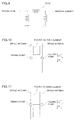
Fig. 10 schematically illustrates a multi-antenna apparatus constituted by a dipole antenna according to a modification of each of the first to third embodiments of the present invention; -
Fig. 11 schematically illustrates a multi-antenna apparatus constituted by a dipole antenna according to a modification of each of the first to third embodiments of the present invention; -
Fig. 12 schematically illustrates a T matching circuit according to a modification of the third embodiment of the present invention; and -
Fig. 13 schematically illustrates an L matching circuit according to a modification of the third - Embodiments of the present invention are now described with reference to the drawings.
- First, the structure of a
mobile phone 100 according to a first embodiment of the present invention is described with reference toFigs. 1 and 2 . Themobile phone 100 is an example of the "mobile device" in the present invention. - The
mobile phone 100 according to the first embodiment of the present invention has a substantially rectangular shape in front elevational view, as shown inFig. 1 . Themobile phone 100 comprises adisplay screen portion 1,operating portions 2 constituted by number buttons and so on, amicrophone 3 and aspeaker 4. Amulti-antenna apparatus 10 is provided inside a housing of themobile phone 100. - The
multi-antenna apparatus 10 is formed for MIMO (Multiple-Input Multiple-Output) communication enabling multiple inputs/outputs at a prescribed frequency employing a plurality of antenna elements. Themulti-antenna apparatus 10 corresponds to WiMAX (Worldwide Interoperability for Microwave Access), which is a highspeed wireless communication network of 2.5 GHz band. - The
multi-antenna apparatus 10 includes afirst antenna element 11 and asecond antenna element 12, apassive antenna element 13 arranged between the twoantenna elements ground surface 14, and afirst feeding point 15 for supplying high-frequency power to thefirst antenna element 11 and asecond feeding point 16 for supplying high-frequency power to thesecond antenna element 12, as shown inFig. 2 . - The
first antenna element 11 is arranged on a side of thepassive antenna element 13 in a direction X1, and thesecond antenna element 12 is arranged on a side of thepassive antenna element 13 in a direction X2. The first antenna element 11 (second antenna element 12) has a thin plate shape and is provided on a surface of a substrate (not shown). The first antenna element 11 (second antenna element 12) is a monopole antenna having an electrical length of about a quarter of a wavelength λ of 2.6 GHz to which themulti-antenna apparatus 10 corresponds. More specifically, an end of the first antenna element 11 (second antenna element 12) in a direction Y1 is open, and an end thereof in a direction Y2 is grounded on theground surface 14. Thefirst antenna element 11 and thesecond antenna element 12 are formed to extend along arrow Y and arranged substantially parallel to each other. Thefirst antenna element 11 is so arranged that a separate distance D1 from thesecond antenna element 12, which is a center-to-center distance, is less than λ/4. The electrical length is not a physical length but a length based on delay time of a signal. - The
passive antenna element 13 has a first opposingportion 131 opposed to thefirst antenna element 11, a second opposingportion 132 opposed to thesecond antenna element 12 and acoupling portion 133 coupling the first opposingportion 131 and the second opposingportion 132 with each other. Thepassive antenna element 13 is so formed as to be in an ungrounded state of not being grounded on theground surface 14. Thepassive antenna element 13 has an electrical length of about λ/2. Thepassive antenna element 13 is formed to resonate due to currents flowing in thefirst antenna element 11 and thesecond antenna element 12. - The first opposing
portion 131 and the second opposingportion 132 are formed to extend along arrow Y and arranged substantially parallel to each other. In other words, thefirst antenna element 11, the first opposingportion 131, the second opposingportion 132 and thesecond antenna element 12 are arranged substantially parallel to each other. Thepassive antenna element 13 is arranged between a straight line connecting the ends of thefirst antenna element 11 and thesecond antenna element 12 in the direction Y1 and a straight line connecting the ends of thefirst antenna element 11 and thesecond antenna element 12 in the direction Y2. The first opposingportion 131 is spaced apart a distance enabling an electrostatic coupling to thefirst antenna element 11 therefrom. The second opposingportion 132 is spaced apart a distance enabling an electrostatic coupling to thesecond antenna element 12 therefrom. Thecoupling portion 133 couples ends of the first opposingportion 131 and the second opposingportion 132 in the direction Y1 with each other. Thecoupling portion 133 is formed to extend along arrow X. Thus, the passiveantennal element 13 is formed in a substantially U shape by the first opposingportion 131, the second opposingportion 132 and thecoupling portion 133. Thus, currents in opposite directions flow in the first opposingportion 131 and the second opposingportion 132. - The first feeding point 15 (second feeding point 16) is arranged on the ends of the first antenna element 11 (second antenna element 12) in the direction Y2. The first feeding point 15 (second feeding point 16) connects the first antenna element 11 (second antenna element 12) and a feeder (not shown) with each other.
- According to the first embodiment, as hereinabove described, the
passive antenna element 13 including the first opposingportion 131 opposed to thefirst antenna element 11, the second opposingportion 132 opposed to thesecond antenna element 12 and thecoupling portion 133 coupling the first opposingportion 131 and the second opposingportion 132 with each other is provided, whereby a direct coupling not through thepassive antenna element 13 and an indirect coupling through thepassive antenna element 13 can be formed between thefirst antenna element 11 and thesecond antenna element 12. In other words, when a current flows in thefirst antenna element 11, a current flowing in thesecond antenna element 12 by the direct coupling to thefirst antenna element 11 and a current flowing in thesecond antenna element 12 through the first opposingportion 131, thecoupling portion 133 and the second opposingportion 132 of thepassive antenna element 13 by the indirect coupling to thefirst antenna element 11 are generated. In the structure according to the first embodiment of the present invention, thepassive antenna element 13 is so arranged that a direction of a current flowing in thefirst antenna element 11 and a direction of a current flowing in the second opposingportion 132 of thepassive antenna element 13 are opposite to each other, and hence a direction of the current flowing in thesecond antenna element 12 due to the direct coupling to thefirst antenna element 11 and a direction of the current flowing in thesecond antenna element 12 due to the indirect coupling to thefirst antenna element 11 by the current in the second opposingportion 132 of thepassive antenna element 13 can be rendered opposite to each other. Thus, the current due to the direct coupling and the current due to the indirect coupling are offset by each other, and hence a mutual coupling between thefirst antenna element 11 and thesecond antenna element 12 can be reduced. Further, thepassive antenna element 13 is rendered ungrounded, whereby it is not necessary to ground thepassive antenna element 13 on theground surface 14, and hence reduction of flexibility of wiring pattern design can be inhibited. Therefore, in thismobile phone 100, the mutual coupling between the antenna elements can be reduced while inhibiting reduction of flexibility of wiring pattern design. The mutual coupling between the antenna elements can be reduced, and hence it is not necessary to increase the distance between the antenna elements to reduce the mutual coupling between the antenna elements, and themulti-antenna apparatus 10 can be downsized accordingly. Consequently, themobile phone 100 can be downsized. - According to the first embodiment, the first opposing
portion 131 and the second opposingportion 132 of thepassive antenna element 13 are spaced apart the distances enabling the electrostatic couplings to thefirst antenna element 11 and thesecond antenna element 12 therefrom, respectively, whereby the first opposingportion 131 and the second opposingportion 132 can be arranged at closer distances from thefirst antenna element 11 and thesecond antenna element 12 respectively, and hence themulti-antenna apparatus 10 can be downsized as compared with a case of an electromagnetic coupling. - According to the first embodiment, the
passive antenna element 13 is formed to resonate due to the currents flowing in thefirst antenna element 11 and thesecond antenna element 12, whereby energy conversion efficiency becomes maximum, and hence the mutual coupling between thefirst antenna element 11 and thesecond antenna element 12 can be efficiently reduced. - According to the first embodiment, the
passive antenna element 13 has an electrical length of substantially one half of a wavelength λ of a radio wave output from each of thefirst antenna element 11 and thesecond antenna element 12, so that the ungroundedpassive antenna element 13 can easily resonate. - According to the first embodiment, the
first antenna element 11 is so arranged that the minimum separate distance D1 from thesecond antenna element 12 is less than a quarter of the wavelength λ of the radio wave output from each of thefirst antenna element 11 and thesecond antenna element 12, whereby an interval between thefirst antenna element 11 and thesecond antenna element 12 is reduced, and hence the small-sizedmulti-antenna apparatus 10 can be provided. - According to the first embodiment, the
first feeding point 15 for supplying high-frequency power to thefirst antenna element 11 and thesecond feeding point 16 for supplying high-frequency power to thesecond antenna element 12 are provided and thefirst antenna element 11 and thesecond antenna element 12 are so arranged that the distance therebetween is minimum between thefirst feeding point 15 and thesecond feeding point 16, whereby an interval between thefirst feeding point 15 and thesecond feeding point 16 is reduced, and hence themulti-antenna apparatus 10 can be easily downsized. - According to the first embodiment, the
passive antenna element 13 is formed in a substantially U shape by the first opposingportion 131, the second opposingportion 132 and thecoupling portion 133, whereby the direction of the current flowing in the first opposingportion 131 of thepassive antenna element 13 due to a coupling to thefirst antenna element 11 and the direction of the current flowing in the second opposingportion 132 through thecoupling portion 133 can be easily rendered opposite to each other by the simple-shapedpassive antenna element 13. - According to the first embodiment, the
first antenna element 11, thesecond antenna element 12, the first opposingportion 131 and the second opposingportion 132 of thepassive antenna element 13 are arranged substantially parallel to each other, whereby themulti-antenna apparatus 10 can be downsized by a simple arrangement in which all of thefirst antenna element 11, thesecond antenna element 12, the first opposingportion 131 and the second opposingportion 132 of thepassive antenna element 13 are arranged substantially parallel to each other. - According to the first embodiment, the
multi-antenna apparatus 10 further comprises thefirst feeding point 15 for supplying high-frequency power to thefirst antenna element 11 and thesecond feeding point 16 for supplying high-frequency power to thesecond antenna element 12, and thepassive antenna element 13 is arranged between a straight line connecting a first end of thefirst antenna element 11 where thefirst feeding point 15 is arranged and a first end of thesecond antenna element 12 where thesecond feeding point 16 is arranged and a straight line connecting a second end of thefirst antenna element 11 and a second end of thesecond antenna element 12. According to this structure, thepassive antenna element 13 does not protrude from a region between thefirst antenna element 11 and thesecond antenna element 12, and hence themulti-antenna apparatus 10 can be downsized. - According to the first embodiment, the
multi-antenna apparatus 10 is formed to be mountable on themobile phone 100, whereby the small-sizedmulti-antenna apparatus 10 mountable on themobile phone 100 can be provided. - Next, results of a simulation performed for confirming the aforementioned effects of the first embodiment are described. In this simulation, the
multi-antenna apparatus 10 corresponding to the first embodiment shown inFig. 2 and amulti-antenna apparatus 110 according to a comparative example shown inFig. 3 have been compared with each other. - In the
multi-antenna apparatus 10 corresponding to the first embodiment, thefirst antenna element 11 and thesecond antenna element 12 are so arranged that the separate distance D1 is 24 mm less than λ/4. While theantenna elements passive antenna element 13 are provided on the surface of the substrate (not shown) in the aforementioned first embodiment, theantenna elements passive antenna element 13 are provided in a vacuum in this simulation. In order to perform the simulation by a system corresponding to two dimensions, theantenna elements passive antenna element 13 are formed of a conductor having a thickness of 0 mm. - As shown in
Fig. 3 , in themulti-antenna apparatus 110 according to the comparative example, a passive antenna element is not provided between twoantenna elements multi-antenna apparatus 10 provided with the substantially U-shapedpassive antenna element 13 according to the first embodiment. Further, in themulti-antenna apparatus 110 according to the comparative example, theantenna elements multi-antenna apparatus 110 according to the comparative example second embodiment is similar to that of themulti-antenna apparatus 10 corresponding to the aforementioned first embodiment. - Next, S-parameter characteristics of the
multi-antenna apparatus 110 according to the comparative example and themulti-antenna apparatus 10 corresponding to the first embodiment are described with reference toFigs. 4 and5 . S11 of S-parameters shown inFigs. 4 and5 denotes reflection coefficients of an antenna element, and S12 of the S-parameters denotes strength of a mutual coupling between two antenna elements. InFigs. 4 and5 , the axis of abscissas shows frequencies, and the axis of ordinates shows magnitude (unit: dB) of S11 and S12. - In the
multi-antenna apparatus 110 according to the comparative example, as shown inFig. 4 , S11 is about -7 dB and S12 is about -5.8 dB at 2.6 GHz. On the other hand, in themulti-antenna apparatus 10 corresponding to the first embodiment, as shown inFig. 5 , S11 is about -9.5 dB and S12 is about -13.5 dB at 2.6 GHz to which themulti-antenna apparatus 10 corresponds. Consequently, S12 denoting strength (magnitude) of a mutual coupling between two antenna elements is smaller in themulti-antenna apparatus 10 corresponding to the first embodiment than in themulti-antenna apparatus 110 according to the comparative example, and hence it has been proved possible to reduce the mutual coupling between the antenna elements by providing the substantially U-shaped ungroundedpassive antenna element 13. When S12 is not more than -10 dB, the mutual coupling between the antenna elements is conceivably fairly small. - This is conceivably for the following reason. In other words, a direct coupling due to the current flowing in the
first antenna element 11 and an indirect coupling due to the current flowing in the second opposingportion 132 of thepassive antenna element 13 are caused in thesecond antenna element 12 of themulti-antenna apparatus 10 corresponding to the first embodiment, and the currents due to the direct coupling and the indirect coupling are offset by each other, whereby the mutual coupling between the antenna elements is conceivably reduced. - S11 denoting reflection coefficients of an antenna element is smaller in the
multi-antenna apparatus 10 corresponding to the first embodiment than in themulti-antenna apparatus 110 according to the comparative example, and hence it has been proved possible to output radio waves efficiently from the antenna elements by providing the substantially U-shaped ungroundedpassive antenna element 13. - A
multi-antenna apparatus 20 of amobile phone 100 according to a second embodiment of the present invention is now described with reference toFig. 6 . In this second embodiment, themulti-antenna apparatus 20 in which afirst antenna element 21, asecond antenna element 22 and first and second opposingportions passive antenna element 23 are formed to be bent at a plurality of positions is described, dissimilarly to the aforementioned first embodiment. - As shown in
Fig. 6 , themulti-antenna apparatus 20 of themobile phone 100 according to the second embodiment includes the first andsecond antenna elements passive antenna element 23 arranged between the twoantenna elements ground surface 14, afirst feeding point 15 for supplying high-frequency power to thefirst antenna element 21 and asecond feeding point 16 for supplying high-frequency power to thesecond antenna element 22. - The
first antenna element 21 is arranged on a side of thepassive antenna element 23 in a direction X1, and thesecond antenna element 22 is arranged on a side of thepassive antenna element 23 in a direction X2. The first antenna element 21 (second antenna element 22) has a thin plate shape and is provided on a surface of a substrate (not shown). Further, the first antenna element 21 (second antenna element 22) is a monopole antenna having an electrical length of about a quarter of a wavelength λ of 2.6 GHz to which themulti-antenna apparatus 20 corresponds. More specifically, an end of the first antenna element 21 (second antenna element 22) in a direction Y1 is open, and an end thereof in a direction Y2 is grounded on theground surface 14. - According to the second embodiment, the
first antenna element 21 and thesecond antenna element 22 are formed to be bent at the plurality of positions. The end of thefirst antenna element 21 in the direction Y1 is arranged at a position deviating in the direction X1 with respect to the end thereof in the direction Y2, and the end of thesecond antenna element 22 in the direction Y1 is arranged at a position deviating in the direction X2 with respect to the end thereof in the direction Y2, dissimilarly to the aforementioned first embodiment. Thefirst antenna element 21 is so arranged that a separate distance D3 at thefirst feeding point 15 from thesecond antenna element 22 is less than λ/4. Thefirst antenna element 21 and thesecond antenna element 22 are so arranged that the distance (D3) therebetween is minimum between thefirst feeding point 15 and thesecond feeding point 16. - The
passive antenna element 23 has the first opposingportion 231 opposed to thefirst antenna element 21, the second opposingportion 232 opposed to thesecond antenna element 22 and acoupling portion 233 coupling the first opposingportion 231 and the second opposingportion 232 with each other. Thepassive antenna element 23 is so formed as to be in an ungrounded state of not being grounded on theground surface 14. Thepassive antenna element 23 has an electrical length of about λ/2. - According to the second embodiment, the
passive antenna element 23 has a substantially U shape as seen as a whole, whereas the first opposingportion 231 and the second opposingportion 232 of thepassive antenna element 23 are formed to be bent at the plurality of positions. A separate distance between thefirst antenna element 21 and the first opposingportion 231 varies along arrow Y, and a separate distance between thesecond antenna element 22 and the second opposingportion 232 varies along arrow Y. Thepassive antenna element 23 is arranged between a straight line connecting the ends of thefirst antenna element 21 and thesecond antenna element 22 in the direction Y1 and a straight line connecting the ends of thefirst antenna element 21 and thesecond antenna element 22 in the direction Y2. The first opposingportion 231 is spaced apart a distance enabling an electrostatic coupling to thefirst antenna element 21 therefrom. The second opposingportion 232 is spaced apart a distance enabling an electrostatic coupling to thesecond antenna element 22 therefrom. - The
coupling portion 233 is arranged to couple ends of the first opposingportion 231 and the second opposingportion 232 in the direction Y1 with each other. Thecoupling portion 233 is formed to extend along arrow X. - The remaining structure of the second embodiment is similar to that of the aforementioned first embodiment.
- As hereinabove described, also in the structure of the second embodiment, a mutual coupling between the antenna elements can be reduced while inhibiting reduction of flexibility of wiring pattern design, similarly to the aforementioned first embodiment. The mutual coupling between the antenna elements can be reduced, and hence it is not necessary to increase the distance between the antenna elements to reduce the mutual coupling between the antenna elements, and the
multi-antenna apparatus 20 can be downsized accordingly. Consequently, themobile phone 100 can be downsized. - According to the second embodiment, as hereinabove described, the
first antenna element 21, thesecond antenna element 22, and the first opposingportion 231 and the second opposingportion 232 of thepassive antenna element 23 are formed to be bent at the plurality of positions, whereby a length required to arrange thefirst antenna element 21, thesecond antenna element 22 and thepassive antenna element 23 can be ensured due to bent shapes thereof also when areas where thefirst antenna element 21, thesecond antenna element 22 and thepassive antenna element 23 are arranged are small, and hence it is not necessary to enlarge the areas where thefirst antenna element 21, thesecond antenna element 22 and thepassive antenna element 23 are arranged. Thus, the multi-antenna apparatus can be downsized. - The remaining effects of the second embodiment are similar to those of the aforementioned first embodiment.
- Next, results of a simulation performed for confirming the aforementioned effects of the second embodiment are described. In this simulation, the
multi-antenna apparatus 20 corresponding to the second embodiment and themulti-antenna apparatus 110 according to the aforementioned comparative example shown inFig. 3 have been compared with each other. - In the
multi-antenna apparatus 20 corresponding to the second embodiment, thefirst antenna element 21 and thesecond antenna element 22 are so arranged that the minimum separate distance D3 is 14 mm less than λ/4. Theantenna elements passive antenna element 23 are provided on a surface of a glass epoxy substrate (not shown) having a thickness of 0.8 mm in the aforementioned second embodiment. In order to perform the simulation by a system corresponding to two dimensions, theantenna elements passive antenna element 23 are formed of a conductor having a thickness of 0 mm. - Next, S-parameter characteristics of the
multi-antenna apparatus 110 according to the comparative example and themulti-antenna apparatus 20 corresponding to the second embodiment are described with reference toFigs. 4 and7 . - As hereinabove described, in the
multi-antenna apparatus 110 according to the comparative example, S11 is about -7 dB and S12 is about -5.8 dB at 2.6 GHz, as shown inFig. 4 . On the other hand, in themulti-antenna apparatus 20 corresponding to the second embodiment, S11 is about -16 dB and S12 is about -25 dB at 2.6 GHz to which themulti-antenna apparatus 20 corresponds, as shown inFig. 7 . - Consequently, S12 denoting strength of a mutual coupling between two antenna elements is smaller in the
multi-antenna apparatus 20 corresponding to the second embodiment than in themulti-antenna apparatus 110 according to the comparative example, and hence it has been proved possible to reduce the mutual coupling between the antenna elements also when thefirst antenna element 21, thesecond antenna element 22, and the first opposingportion 231 and the second opposingportion 232 of thepassive antenna element 23 are formed to be bent at the plurality of positions. - S11 denoting reflection coefficients of an antenna element is smaller in the
multi-antenna apparatus 20 corresponding to the second embodiment than in themulti-antenna apparatus 110 according to the comparative example, and hence it has been proved possible to output radio waves efficiently from the antenna elements also when thefirst antenna element 21, thesecond antenna element 22, and the first opposingportion 231 and the second opposingportion 232 of thepassive antenna element 23 are formed to be bent at the plurality of positions. - Further, it has been proved possible to render both values of S11 and S12 smaller in the
multi-antenna apparatus 20 than in themulti-antenna apparatus 10 corresponding to the first embodiment while further downsizing themulti-antenna apparatus 20 by forming thefirst antenna element 21, thesecond antenna element 22 and thepassive antenna element 23 to be bent, compared to themulti-antenna apparatus 10 corresponding to the first embodiment. - A
multi-antenna apparatus 30 of amobile phone 100 according to a third embodiment of the present invention is now described with reference toFigs. 8 and9 . In this third embodiment, themulti-antenna apparatus 30 including afirst matching circuit 31 arranged between afirst antenna element 11 and afirst feeding point 15 and asecond matching circuit 32 arranged between asecond antenna element 12 and asecond feeding point 16 is described, dissimilarly to the aforementioned first embodiment. - The
multi-antenna apparatus 30 of themobile phone 100 according to the third embodiment includes thefirst matching circuit 31 arranged between thefirst antenna element 11 and thefirst feeding point 15 and thesecond matching circuit 32 arranged between thesecond antenna element 12 and thesecond feeding point 16, as shown inFig. 8 . - The first matching circuit 31 (second matching circuit 32) has a function of reducing transfer loss of energy by impedance matching at 2.6 GHz to which the
multi-antenna apparatus 30 corresponds. The first matching circuit 31 (second matching circuit 32) is provided for inhibiting a mutual coupling between the antenna elements while matching impedance at 2.6 GHz to which themulti-antenna apparatus 30 corresponds. More specifically, impedance of the first matching circuit 31 (second matching circuit 32) is adjusted, whereby a minimum value of S12 denoting strength of a mutual coupling between two antenna elements can be easily located in the vicinity of a desired frequency. The first matching circuit 31 (second matching circuit 32) is constituted by a π circuit (π match) made of an inductor (coil), as shown inFig. 9 . - The remaining structure of the third embodiment is similar to that of the aforementioned first embodiment.
- As hereinabove described, also in the structure of the third embodiment, the mutual coupling between the antenna elements can be reduced while inhibiting reduction of flexibility of wiring pattern design, similarly to the aforementioned first embodiment. The mutual coupling between the antenna elements can be reduced, and hence it is not necessary to increase a distance between the antenna elements to reduce the mutual coupling between the antenna elements, and the
multi-antenna apparatus 30 can be downsized accordingly. Consequently, themobile phone 100 can be downsized. - According to the third embodiment, as hereinabove described, the
first matching circuit 31 arranged between thefirst antenna element 11 and thefirst feeding point 15 for inhibiting the mutual coupling between thefirst antenna element 11 and thesecond antenna element 12 while matching impedance at a prescribed frequency of high-frequency power and thesecond matching circuit 32 arranged between thesecond antenna element 12 and thesecond feeding point 16 for inhibiting the mutual coupling between thefirst antenna element 11 and thesecond antenna element 12 while matching impedance at the prescribed frequency of the high-frequency power are provided, whereby the mutual coupling between the antenna elements can be reduced while matching impedance at the prescribed frequency, and hence transfer loss of energy transferred through the antenna elements can be further reduced. - The remaining effects of the third embodiment are similar to those of the aforementioned first embodiment.
- Although the present invention has been described and illustrated in detail, it is clearly understood that the same is by way of illustration and example only and is not to be taken by way of limitation, the spirit and scope of the present invention being limited only by the terms of the appended claims.
- For example, while the mobile phone is shown as an exemplary mobile device comprising a multi-antenna apparatus in each of the aforementioned first to third embodiments, the present invention is not restricted to this. The present invention is also applicable to another mobile device other than the mobile phone, such as a PDA (Personal Digital Assistant) or a small-sized notebook computer comprising a multi-antenna apparatus. Alternatively, the present invention is also applicable to another device, other than the mobile device, comprising a multi-antenna apparatus.
- While the multi-antenna apparatus for MIMO communication is shown as an exemplary multi-antenna apparatus in each of the aforementioned first to third embodiments, the present invention is not restricted to this. In the present invention, a multi-antenna apparatus corresponding to another system other than MIMO, such as Diversity may be employed.
- While the multi-antenna apparatus is formed to correspond to WiMAX of 2.5 GHz band in each of the aforementioned first to third embodiments, the present invention is not restricted to this. In the present invention, the multi-antenna apparatus may be formed to correspond to a frequency other than 2.5 GHz band or may be formed to correspond to another system other than WiMAX, such as GSM or 3G, for example.
- While the two antenna elements are provided on the multi-antenna apparatus in each of the aforementioned first to third embodiments, the present invention is not restricted to this. In the present invention, more than two antenna elements may be provided so far as there are a plurality of antenna elements. In this case, a plurality of passive antenna elements may be provided.
- While the first antenna element (second antenna element) constituted by a monopole antenna is shown as an exemplary first antenna element (second antenna element) in each of the aforementioned first to third embodiments, the present invention is not restricted to this. In the present invention, a first antenna element (second antenna element) other than a monopole antenna, such as a dipole antenna may be employed. For example, as shown in
Fig. 10 , a substantially U-shaped ungrounded passive antenna element may be so provided as to correspond to a portion closer to a side of a direction Y1 than a feeding point of a first antenna element (second antenna element) in a case of the first antenna element (second antenna element) constituted by a dipole antenna. Alternatively, as shown inFig. 11 , a substantially H-shaped ungrounded passive antenna element may be so provided as to correspond to both a portion closer to a side of a direction Y1 and a portion closer to a side of a direction Y2 than a feeding point of a first antenna element (second antenna element) constituted by a dipole antenna. - While the coupling portion of the passive antenna element couples the ends of the first and second opposing portions in the direction Y1 with each other in each of the aforementioned first to third embodiments, the present invention is not restricted to this. In the present invention, a coupling portion of the passive antenna element may couple ends of the first and second opposing portions in the direction Y2 or a coupling portion may couple another parts of the first and second opposing portions other than the ends thereof, so far as currents in opposite directions flow in the first and second opposing portions.
- While the first matching circuit (second matching circuit) constituted by the π circuit (π match) made of an inductor (coil) is provided in the aforementioned third embodiment, the present invention is not restricted to this. In the present invention, a first matching circuit (second matching circuit) formed in another shape other than the π circuit, such as a T circuit (T match) made of an inductor (coil) shown in
Fig. 12 or an L circuit (L match) made of an inductor (coil) shown inFig. 13 may be provided. Alternatively, the π circuits, the T circuits, the L circuits or the like may be made of only either an inductor (coil) or a capacitor (condenser) or may be made of both an inductor (coil) and a capacitor (condenser). - While the first antenna element, the second antenna element, and the first and second opposing portions of the passive antenna element are formed to be bent at the plurality of positions in the aforementioned second embodiment, the present invention is not restricted to this. In the present invention, the first antenna element, the second antenna element, and the first and second opposing portions may be formed to be curved at a plurality of positions.
- While the first antenna element, the second antenna element, and the first and second opposing portions of the passive antenna element are formed to extend along arrow Y in the aforementioned first and third embodiments, the present invention is not restricted to this. In the present invention, parts of the first antenna element, the second antenna element, and the first and second opposing portions may be formed to be bent or curved at a prescribed position.
- While the coupling portion of the passive antenna element is formed to extend along arrow X in the aforementioned first to third embodiments, the present invention is not restricted to this. In the present invention, the coupling portion may be formed to be bent or curved at a prescribed position.
Claims (15)
- A multi-antenna apparatus (10, 20, 30) comprising:a first antenna element (11, 21) and a second antenna element (12, 22); andan ungrounded passive antenna element (13, 23) arranged between said first antenna element and said second antenna element, whereinsaid passive antenna element includes a first opposing portion (131, 231) opposed to said first antenna element, a second opposing portion (132, 232) opposed to said second antenna element and a coupling portion (133, 233) coupling said first opposing portion and said second opposing portion with each other.
- The multi-antenna apparatus according to claim 1, wherein
said coupling portion of said passive antenna element is formed to couple said first opposing portion and said second opposing portion with each other such that currents in opposite directions flow in said first opposing portion and said second opposing portion. - The multi-antenna apparatus according to claim 1, wherein
said first opposing portion and said second opposing portion of said passive antenna element are spaced apart distances enabling electrostatic couplings to said first antenna element and said second antenna element therefrom, respectively. - The multi-antenna apparatus according to claim 1, wherein
said passive antenna element is formed to resonate due to currents flowing in said first antenna element and said second antenna element. - The multi-antenna apparatus according to claim 4, wherein
said passive antenna element has an electrical length of one half of a wavelength π of a radio wave output from each of said first antenna element and said second antenna element. - The multi-antenna apparatus according to claim 1, wherein
said first antenna element is so arranged that a minimum separate distance from said second antenna element is less than a quarter of a wavelength π of a radio wave output from each of said first antenna element and said second antenna element. - The multi-antenna apparatus according to claim 6, further comprising:a first feeding point (15) for supplying high-frequency power to said first antenna element; anda second feeding point (16) for supplying high-frequency power to said second antenna element, whereinsaid first antenna element and said second antenna element are so arranged that a distance therebetween is minimum between said first feeding point and said second feeding point.
- The multi-antenna apparatus according to claim 1, further comprising:a first feeding point (15) for supplying high-frequency power to said first antenna element and a second feeding point (16) for supplying high-frequency power to said second antenna element;a first matching circuit (31) arranged between said first antenna element and said first feeding point for inhibiting a mutual coupling between said first antenna element and said second antenna element while matching impedance at a prescribed frequency of high-frequency power; anda second matching circuit (32) arranged between said second antenna element and said second feeding point for inhibiting the mutual coupling between said first antenna element and said second antenna element while matching impedance at the prescribed frequency of high-frequency power.
- The multi-antenna apparatus according to claim 2, wherein
said passive antenna element is formed in a U shape by said first opposing portion, said second opposing portion and said coupling portion. - The multi-antenna apparatus according to claim 1, wherein
said first antenna element, said second antenna element, and said first opposing portion and said second opposing portion of said passive antenna element are formed to be bent or curved at a plurality of positions. - The multi-antenna apparatus according to claim 1, wherein
said first antenna element and said second antenna element each include a monopole antenna. - The multi-antenna apparatus according to claim 1, wherein
said first antenna element and said second antenna element each include a dipole antenna. - The multi-antenna apparatus according to claim 1, wherein
said first antenna element, said second antenna element, and said first opposing portion and said second opposing portion of said passive antenna element are arranged parallel to each other. - The multi-antenna apparatus according to claim 1, further comprising:a first feeding point (15) for supplying high-frequency power to said first antenna element; anda second feeding point (16) for supplying high-frequency power to said second antenna element, whereinsaid passive antenna element is arranged between a straight line connecting a first end of said first antenna element on a side on which said first feeding point is arranged and a first end of said second antenna element on a side on which said second feeding point is arranged and a straight line connecting a second end of said first antenna element and a second end of said second antenna element.
- The multi-antenna apparatus according to claim 1, formed to be mountable on a mobile device (100).
Applications Claiming Priority (1)
| Application Number | Priority Date | Filing Date | Title |
|---|---|---|---|
| JP2009264448A JP5532847B2 (en) | 2009-11-20 | 2009-11-20 | Multi-antenna device and portable device |
Publications (2)
| Publication Number | Publication Date |
|---|---|
| EP2328228A1 true EP2328228A1 (en) | 2011-06-01 |
| EP2328228B1 EP2328228B1 (en) | 2016-03-02 |
Family
ID=43597832
Family Applications (1)
| Application Number | Title | Priority Date | Filing Date |
|---|---|---|---|
| EP10191877.9A Not-in-force EP2328228B1 (en) | 2009-11-20 | 2010-11-19 | Multi-antenna apparatus |
Country Status (3)
| Country | Link |
|---|---|
| US (1) | US8593366B2 (en) |
| EP (1) | EP2328228B1 (en) |
| JP (1) | JP5532847B2 (en) |
Cited By (5)
| Publication number | Priority date | Publication date | Assignee | Title |
|---|---|---|---|---|
| EP2575208A1 (en) * | 2011-09-28 | 2013-04-03 | Sony Mobile Communications AB | Multi-band wireless terminal with multiple antennas along an end portion of a backplate |
| EP2610964A1 (en) * | 2011-12-26 | 2013-07-03 | Funai Electric Co., Ltd. | Multi-antenna device and communication apparatus |
| DE102013100731A1 (en) * | 2012-09-26 | 2014-04-17 | Mediatek Singapore Pte. Ltd. | Communication device and antennas with high isolation properties |
| US9583824B2 (en) | 2011-09-28 | 2017-02-28 | Sony Corporation | Multi-band wireless terminals with a hybrid antenna along an end portion, and related multi-band antenna systems |
| CN107394373A (en) * | 2017-06-14 | 2017-11-24 | 中国电子科技集团公司第三十六研究所 | A kind of low-cross coupling antenna array of Meta Materials loading |
Families Citing this family (46)
| Publication number | Priority date | Publication date | Assignee | Title |
|---|---|---|---|---|
| US8744384B2 (en) | 2000-07-20 | 2014-06-03 | Blackberry Limited | Tunable microwave devices with auto-adjusting matching circuit |
| US9406444B2 (en) | 2005-11-14 | 2016-08-02 | Blackberry Limited | Thin film capacitors |
| US7711337B2 (en) | 2006-01-14 | 2010-05-04 | Paratek Microwave, Inc. | Adaptive impedance matching module (AIMM) control architectures |
| US7714676B2 (en) | 2006-11-08 | 2010-05-11 | Paratek Microwave, Inc. | Adaptive impedance matching apparatus, system and method |
| US7535312B2 (en) | 2006-11-08 | 2009-05-19 | Paratek Microwave, Inc. | Adaptive impedance matching apparatus, system and method with improved dynamic range |
| US7917104B2 (en) | 2007-04-23 | 2011-03-29 | Paratek Microwave, Inc. | Techniques for improved adaptive impedance matching |
| US7991363B2 (en) | 2007-11-14 | 2011-08-02 | Paratek Microwave, Inc. | Tuning matching circuits for transmitter and receiver bands as a function of transmitter metrics |
| US8072285B2 (en) | 2008-09-24 | 2011-12-06 | Paratek Microwave, Inc. | Methods for tuning an adaptive impedance matching network with a look-up table |
| US9026062B2 (en) | 2009-10-10 | 2015-05-05 | Blackberry Limited | Method and apparatus for managing operations of a communication device |
| US8803631B2 (en) | 2010-03-22 | 2014-08-12 | Blackberry Limited | Method and apparatus for adapting a variable impedance network |
| CN102948083B (en) | 2010-04-20 | 2015-05-27 | 黑莓有限公司 | Method and apparatus for managing interference in a communication device |
| US9379454B2 (en) | 2010-11-08 | 2016-06-28 | Blackberry Limited | Method and apparatus for tuning antennas in a communication device |
| CN102104193B (en) * | 2010-12-01 | 2015-04-01 | 中兴通讯股份有限公司 | Multiple input multiple output antenna system |
| US8712340B2 (en) | 2011-02-18 | 2014-04-29 | Blackberry Limited | Method and apparatus for radio antenna frequency tuning |
| JP5673270B2 (en) * | 2011-03-22 | 2015-02-18 | 船井電機株式会社 | Multi-antenna device and communication device |
| US8655286B2 (en) | 2011-02-25 | 2014-02-18 | Blackberry Limited | Method and apparatus for tuning a communication device |
| CN102760949A (en) * | 2011-04-27 | 2012-10-31 | 鸿富锦精密工业(深圳)有限公司 | Multiple-input-and-output antenna |
| US8594584B2 (en) | 2011-05-16 | 2013-11-26 | Blackberry Limited | Method and apparatus for tuning a communication device |
| WO2013022826A1 (en) | 2011-08-05 | 2013-02-14 | Research In Motion Rf, Inc. | Method and apparatus for band tuning in a communication device |
| KR101293660B1 (en) * | 2011-08-29 | 2013-08-13 | 엘에스엠트론 주식회사 | MIMO/diversity antenna with high isolation |
| CN103094672B (en) * | 2011-10-28 | 2015-03-11 | 鸿富锦精密工业(深圳)有限公司 | Antenna |
| TWI493789B (en) * | 2011-10-28 | 2015-07-21 | Hon Hai Prec Ind Co Ltd | An antenna |
| JP5871647B2 (en) * | 2012-02-17 | 2016-03-01 | 三菱電機株式会社 | Decoupling circuit |
| TWI511378B (en) * | 2012-04-03 | 2015-12-01 | Ind Tech Res Inst | Multi-band multi-antenna system and communiction device thereof |
| JP5631921B2 (en) | 2012-04-17 | 2014-11-26 | 太陽誘電株式会社 | Multi-antenna and electronic device |
| US8948889B2 (en) | 2012-06-01 | 2015-02-03 | Blackberry Limited | Methods and apparatus for tuning circuit components of a communication device |
| US9853363B2 (en) * | 2012-07-06 | 2017-12-26 | Blackberry Limited | Methods and apparatus to control mutual coupling between antennas |
| US9246223B2 (en) | 2012-07-17 | 2016-01-26 | Blackberry Limited | Antenna tuning for multiband operation |
| US9350405B2 (en) | 2012-07-19 | 2016-05-24 | Blackberry Limited | Method and apparatus for antenna tuning and power consumption management in a communication device |
| US9413066B2 (en) | 2012-07-19 | 2016-08-09 | Blackberry Limited | Method and apparatus for beam forming and antenna tuning in a communication device |
| US9362891B2 (en) | 2012-07-26 | 2016-06-07 | Blackberry Limited | Methods and apparatus for tuning a communication device |
| US10404295B2 (en) | 2012-12-21 | 2019-09-03 | Blackberry Limited | Method and apparatus for adjusting the timing of radio antenna tuning |
| US9374113B2 (en) | 2012-12-21 | 2016-06-21 | Blackberry Limited | Method and apparatus for adjusting the timing of radio antenna tuning |
| JP5947263B2 (en) * | 2013-08-27 | 2016-07-06 | Necプラットフォームズ株式会社 | Antenna and wireless communication device |
| CN104466354B (en) * | 2013-09-18 | 2019-06-18 | 深圳富泰宏精密工业有限公司 | Antenna structure and wireless communication device with the antenna structure |
| JP6465109B2 (en) | 2014-05-30 | 2019-02-06 | Agc株式会社 | Multi-antenna and radio apparatus including the same |
| TWI539674B (en) * | 2014-09-26 | 2016-06-21 | 宏碁股份有限公司 | Antenna system |
| CN105514606A (en) * | 2014-10-14 | 2016-04-20 | 宏碁股份有限公司 | Antenna system |
| US9438319B2 (en) | 2014-12-16 | 2016-09-06 | Blackberry Limited | Method and apparatus for antenna selection |
| WO2018038079A1 (en) * | 2016-08-25 | 2018-03-01 | 株式会社村田製作所 | Antenna device |
| WO2018079415A1 (en) * | 2016-10-25 | 2018-05-03 | 日本板硝子株式会社 | Window glass |
| TWI682583B (en) * | 2017-11-30 | 2020-01-11 | 財團法人金屬工業研究發展中心 | Multi-antenna system using non-radiative coupling edges to achieve isolation |
| CN108493600B (en) * | 2018-04-08 | 2024-01-16 | 深圳市信维通信股份有限公司 | A 5G MIMO antenna structure |
| US11342671B2 (en) * | 2019-06-07 | 2022-05-24 | Sonos, Inc. | Dual-band antenna topology |
| TWI726694B (en) * | 2020-04-21 | 2021-05-01 | 國立臺灣科技大學 | Phase controlled optical waveguide antenna array |
| JP6984951B2 (en) * | 2020-04-22 | 2021-12-22 | Necプラットフォームズ株式会社 | Antenna device and wireless communication device |
Citations (4)
| Publication number | Priority date | Publication date | Assignee | Title |
|---|---|---|---|---|
| US20060038736A1 (en) * | 2004-08-20 | 2006-02-23 | Nokia Corporation | Isolation between antennas using floating parasitic elements |
| EP0958636B1 (en) * | 1997-02-05 | 2006-04-05 | Allgon Ab | Antenna operating with two isolated channels |
| EP1768211A1 (en) * | 2005-09-27 | 2007-03-28 | Samsung Electronics Co., Ltd. | Flat-plate mimo array antenna with an isolation element |
| GB2458492A (en) * | 2008-03-19 | 2009-09-23 | Thales Holdings Uk Plc | Antenna array with reduced mutual antenna element coupling |
Family Cites Families (11)
| Publication number | Priority date | Publication date | Assignee | Title |
|---|---|---|---|---|
| JP4082674B2 (en) * | 2003-03-10 | 2008-04-30 | ソニー・エリクソン・モバイルコミュニケーションズ株式会社 | ANTENNA DEVICE AND RADIO DEVICE |
| JP2006042111A (en) * | 2004-07-29 | 2006-02-09 | Matsushita Electric Ind Co Ltd | Antenna device |
| JP2006108830A (en) | 2004-10-01 | 2006-04-20 | Ngk Spark Plug Co Ltd | ANTENNA DEVICE, WIRELESS COMMUNICATION DEVICE USING THE SAME, AND METHOD FOR MANUFACTURING ANTENNA DEVICE |
| JP4667310B2 (en) | 2006-07-04 | 2011-04-13 | 株式会社エヌ・ティ・ティ・ドコモ | Multi-antenna with parasitic elements |
| JP4571988B2 (en) * | 2007-01-19 | 2010-10-27 | パナソニック株式会社 | Array antenna device and wireless communication device |
| JP2008245132A (en) | 2007-03-28 | 2008-10-09 | Toshiba Corp | Radio device |
| US7688273B2 (en) | 2007-04-20 | 2010-03-30 | Skycross, Inc. | Multimode antenna structure |
| US7688275B2 (en) | 2007-04-20 | 2010-03-30 | Skycross, Inc. | Multimode antenna structure |
| US8866691B2 (en) | 2007-04-20 | 2014-10-21 | Skycross, Inc. | Multimode antenna structure |
| JP4966125B2 (en) * | 2007-07-27 | 2012-07-04 | 株式会社東芝 | Antenna device and radio |
| JP2009246560A (en) * | 2008-03-28 | 2009-10-22 | Ngk Spark Plug Co Ltd | Antenna device and radio communication apparatus with the same |
-
2009
- 2009-11-20 JP JP2009264448A patent/JP5532847B2/en not_active Expired - Fee Related
-
2010
- 2010-11-19 EP EP10191877.9A patent/EP2328228B1/en not_active Not-in-force
- 2010-11-19 US US12/949,994 patent/US8593366B2/en not_active Expired - Fee Related
Patent Citations (5)
| Publication number | Priority date | Publication date | Assignee | Title |
|---|---|---|---|---|
| EP0958636B1 (en) * | 1997-02-05 | 2006-04-05 | Allgon Ab | Antenna operating with two isolated channels |
| US20060038736A1 (en) * | 2004-08-20 | 2006-02-23 | Nokia Corporation | Isolation between antennas using floating parasitic elements |
| EP1768211A1 (en) * | 2005-09-27 | 2007-03-28 | Samsung Electronics Co., Ltd. | Flat-plate mimo array antenna with an isolation element |
| JP2007097167A (en) | 2005-09-27 | 2007-04-12 | Samsung Electronics Co Ltd | Planar MIMO array antenna including isolation elements |
| GB2458492A (en) * | 2008-03-19 | 2009-09-23 | Thales Holdings Uk Plc | Antenna array with reduced mutual antenna element coupling |
Cited By (10)
| Publication number | Priority date | Publication date | Assignee | Title |
|---|---|---|---|---|
| EP2575208A1 (en) * | 2011-09-28 | 2013-04-03 | Sony Mobile Communications AB | Multi-band wireless terminal with multiple antennas along an end portion of a backplate |
| US9583824B2 (en) | 2011-09-28 | 2017-02-28 | Sony Corporation | Multi-band wireless terminals with a hybrid antenna along an end portion, and related multi-band antenna systems |
| US9673520B2 (en) | 2011-09-28 | 2017-06-06 | Sony Corporation | Multi-band wireless terminals with multiple antennas along an end portion, and related multi-band antenna systems |
| EP2610964A1 (en) * | 2011-12-26 | 2013-07-03 | Funai Electric Co., Ltd. | Multi-antenna device and communication apparatus |
| US9077081B2 (en) | 2011-12-26 | 2015-07-07 | Funai Electric Co., Ltd. | Multi-antenna device and communication apparatus |
| DE102013100731A1 (en) * | 2012-09-26 | 2014-04-17 | Mediatek Singapore Pte. Ltd. | Communication device and antennas with high isolation properties |
| US8922448B2 (en) | 2012-09-26 | 2014-12-30 | Mediatek Singapore Pte. Ltd. | Communication device and antennas with high isolation characteristics |
| DE102013100731B4 (en) | 2012-09-26 | 2018-10-11 | Mediatek Singapore Pte. Ltd. | Communication device and antennas with high isolation properties |
| CN107394373A (en) * | 2017-06-14 | 2017-11-24 | 中国电子科技集团公司第三十六研究所 | A kind of low-cross coupling antenna array of Meta Materials loading |
| CN107394373B (en) * | 2017-06-14 | 2019-12-06 | 中国电子科技集团公司第三十六研究所 | Metamaterial-loaded low-mutual-coupling antenna array |
Also Published As
| Publication number | Publication date |
|---|---|
| JP5532847B2 (en) | 2014-06-25 |
| US8593366B2 (en) | 2013-11-26 |
| EP2328228B1 (en) | 2016-03-02 |
| JP2011109547A (en) | 2011-06-02 |
| US20110122040A1 (en) | 2011-05-26 |
Similar Documents
| Publication | Publication Date | Title |
|---|---|---|
| US8593366B2 (en) | Multi-antenna apparatus and mobile device | |
| US8619001B2 (en) | Multi-antenna apparatus and mobile device | |
| US8890763B2 (en) | Multiantenna unit and communication apparatus | |
| JP5708475B2 (en) | Multi-antenna device and communication device | |
| US9444129B2 (en) | Multi-band compatible multi-antenna device and communication equipment | |
| US9478846B2 (en) | Antenna device | |
| US7242353B2 (en) | Bracket-antenna assembly and manufacturing method of the same | |
| US9590304B2 (en) | Broadband antenna | |
| US9013358B2 (en) | Antenna assembly and wireless communication device provided with the same | |
| US20140002320A1 (en) | Antenna apparatus operable in dualbands with small size | |
| CN101764282B (en) | Electromagnetic radiation device and manufacturing method thereof | |
| US20130113671A1 (en) | Slot antenna | |
| CN106415929A (en) | Multi-antenna and wireless device with the multi-antenna | |
| JP5969821B2 (en) | Antenna device | |
| CN102820523B (en) | multi-frequency antenna | |
| US20170170555A1 (en) | Decoupled Antennas For Wireless Communication | |
| JP5791961B2 (en) | Multi-antenna device and communication device | |
| JP5652133B2 (en) | Multi-antenna device and portable device | |
| US7554488B2 (en) | Planar antenna | |
| US20090278745A1 (en) | Dual-band inverted-f antenna | |
| US11923622B2 (en) | Antenna and wireless communication device | |
| US11233322B2 (en) | Communication device | |
| JP5664322B2 (en) | Multi-antenna device and communication device | |
| US20080291103A1 (en) | Compact diversity antenna arrangement | |
| Zhang et al. | Compact MIMO antenna with embedded decoupling network |
Legal Events
| Date | Code | Title | Description |
|---|---|---|---|
| PUAI | Public reference made under article 153(3) epc to a published international application that has entered the european phase |
Free format text: ORIGINAL CODE: 0009012 |
|
| AK | Designated contracting states |
Kind code of ref document: A1 Designated state(s): AL AT BE BG CH CY CZ DE DK EE ES FI FR GB GR HR HU IE IS IT LI LT LU LV MC MK MT NL NO PL PT RO RS SE SI SK SM TR |
|
| AX | Request for extension of the european patent |
Extension state: BA ME |
|
| 17P | Request for examination filed |
Effective date: 20111021 |
|
| 17Q | First examination report despatched |
Effective date: 20130327 |
|
| GRAP | Despatch of communication of intention to grant a patent |
Free format text: ORIGINAL CODE: EPIDOSNIGR1 |
|
| INTG | Intention to grant announced |
Effective date: 20150810 |
|
| GRAS | Grant fee paid |
Free format text: ORIGINAL CODE: EPIDOSNIGR3 |
|
| GRAA | (expected) grant |
Free format text: ORIGINAL CODE: 0009210 |
|
| AK | Designated contracting states |
Kind code of ref document: B1 Designated state(s): AL AT BE BG CH CY CZ DE DK EE ES FI FR GB GR HR HU IE IS IT LI LT LU LV MC MK MT NL NO PL PT RO RS SE SI SK SM TR |
|
| REG | Reference to a national code |
Ref country code: GB Ref legal event code: FG4D |
|
| REG | Reference to a national code |
Ref country code: AT Ref legal event code: REF Ref document number: 778575 Country of ref document: AT Kind code of ref document: T Effective date: 20160315 Ref country code: CH Ref legal event code: EP |
|
| REG | Reference to a national code |
Ref country code: IE Ref legal event code: FG4D |
|
| REG | Reference to a national code |
Ref country code: DE Ref legal event code: R096 Ref document number: 602010030844 Country of ref document: DE |
|
| REG | Reference to a national code |
Ref country code: NL Ref legal event code: MP Effective date: 20160302 |
|
| REG | Reference to a national code |
Ref country code: LT Ref legal event code: MG4D |
|
| REG | Reference to a national code |
Ref country code: AT Ref legal event code: MK05 Ref document number: 778575 Country of ref document: AT Kind code of ref document: T Effective date: 20160302 |
|
| PG25 | Lapsed in a contracting state [announced via postgrant information from national office to epo] |
Ref country code: FI Free format text: LAPSE BECAUSE OF FAILURE TO SUBMIT A TRANSLATION OF THE DESCRIPTION OR TO PAY THE FEE WITHIN THE PRESCRIBED TIME-LIMIT Effective date: 20160302 Ref country code: GR Free format text: LAPSE BECAUSE OF FAILURE TO SUBMIT A TRANSLATION OF THE DESCRIPTION OR TO PAY THE FEE WITHIN THE PRESCRIBED TIME-LIMIT Effective date: 20160603 Ref country code: NO Free format text: LAPSE BECAUSE OF FAILURE TO SUBMIT A TRANSLATION OF THE DESCRIPTION OR TO PAY THE FEE WITHIN THE PRESCRIBED TIME-LIMIT Effective date: 20160602 Ref country code: HR Free format text: LAPSE BECAUSE OF FAILURE TO SUBMIT A TRANSLATION OF THE DESCRIPTION OR TO PAY THE FEE WITHIN THE PRESCRIBED TIME-LIMIT Effective date: 20160302 Ref country code: ES Free format text: LAPSE BECAUSE OF FAILURE TO SUBMIT A TRANSLATION OF THE DESCRIPTION OR TO PAY THE FEE WITHIN THE PRESCRIBED TIME-LIMIT Effective date: 20160302 |
|
| PG25 | Lapsed in a contracting state [announced via postgrant information from national office to epo] |
Ref country code: LV Free format text: LAPSE BECAUSE OF FAILURE TO SUBMIT A TRANSLATION OF THE DESCRIPTION OR TO PAY THE FEE WITHIN THE PRESCRIBED TIME-LIMIT Effective date: 20160302 Ref country code: AT Free format text: LAPSE BECAUSE OF FAILURE TO SUBMIT A TRANSLATION OF THE DESCRIPTION OR TO PAY THE FEE WITHIN THE PRESCRIBED TIME-LIMIT Effective date: 20160302 Ref country code: NL Free format text: LAPSE BECAUSE OF FAILURE TO SUBMIT A TRANSLATION OF THE DESCRIPTION OR TO PAY THE FEE WITHIN THE PRESCRIBED TIME-LIMIT Effective date: 20160302 Ref country code: SE Free format text: LAPSE BECAUSE OF FAILURE TO SUBMIT A TRANSLATION OF THE DESCRIPTION OR TO PAY THE FEE WITHIN THE PRESCRIBED TIME-LIMIT Effective date: 20160302 Ref country code: RS Free format text: LAPSE BECAUSE OF FAILURE TO SUBMIT A TRANSLATION OF THE DESCRIPTION OR TO PAY THE FEE WITHIN THE PRESCRIBED TIME-LIMIT Effective date: 20160302 Ref country code: LT Free format text: LAPSE BECAUSE OF FAILURE TO SUBMIT A TRANSLATION OF THE DESCRIPTION OR TO PAY THE FEE WITHIN THE PRESCRIBED TIME-LIMIT Effective date: 20160302 Ref country code: PL Free format text: LAPSE BECAUSE OF FAILURE TO SUBMIT A TRANSLATION OF THE DESCRIPTION OR TO PAY THE FEE WITHIN THE PRESCRIBED TIME-LIMIT Effective date: 20160302 |
|
| PG25 | Lapsed in a contracting state [announced via postgrant information from national office to epo] |
Ref country code: EE Free format text: LAPSE BECAUSE OF FAILURE TO SUBMIT A TRANSLATION OF THE DESCRIPTION OR TO PAY THE FEE WITHIN THE PRESCRIBED TIME-LIMIT Effective date: 20160302 Ref country code: IS Free format text: LAPSE BECAUSE OF FAILURE TO SUBMIT A TRANSLATION OF THE DESCRIPTION OR TO PAY THE FEE WITHIN THE PRESCRIBED TIME-LIMIT Effective date: 20160702 |
|
| PG25 | Lapsed in a contracting state [announced via postgrant information from national office to epo] |
Ref country code: RO Free format text: LAPSE BECAUSE OF FAILURE TO SUBMIT A TRANSLATION OF THE DESCRIPTION OR TO PAY THE FEE WITHIN THE PRESCRIBED TIME-LIMIT Effective date: 20160302 Ref country code: SM Free format text: LAPSE BECAUSE OF FAILURE TO SUBMIT A TRANSLATION OF THE DESCRIPTION OR TO PAY THE FEE WITHIN THE PRESCRIBED TIME-LIMIT Effective date: 20160302 Ref country code: SK Free format text: LAPSE BECAUSE OF FAILURE TO SUBMIT A TRANSLATION OF THE DESCRIPTION OR TO PAY THE FEE WITHIN THE PRESCRIBED TIME-LIMIT Effective date: 20160302 Ref country code: PT Free format text: LAPSE BECAUSE OF FAILURE TO SUBMIT A TRANSLATION OF THE DESCRIPTION OR TO PAY THE FEE WITHIN THE PRESCRIBED TIME-LIMIT Effective date: 20160704 Ref country code: CZ Free format text: LAPSE BECAUSE OF FAILURE TO SUBMIT A TRANSLATION OF THE DESCRIPTION OR TO PAY THE FEE WITHIN THE PRESCRIBED TIME-LIMIT Effective date: 20160302 |
|
| REG | Reference to a national code |
Ref country code: DE Ref legal event code: R097 Ref document number: 602010030844 Country of ref document: DE |
|
| PG25 | Lapsed in a contracting state [announced via postgrant information from national office to epo] |
Ref country code: BE Free format text: LAPSE BECAUSE OF FAILURE TO SUBMIT A TRANSLATION OF THE DESCRIPTION OR TO PAY THE FEE WITHIN THE PRESCRIBED TIME-LIMIT Effective date: 20160302 Ref country code: IT Free format text: LAPSE BECAUSE OF FAILURE TO SUBMIT A TRANSLATION OF THE DESCRIPTION OR TO PAY THE FEE WITHIN THE PRESCRIBED TIME-LIMIT Effective date: 20160302 |
|
| PLBE | No opposition filed within time limit |
Free format text: ORIGINAL CODE: 0009261 |
|
| STAA | Information on the status of an ep patent application or granted ep patent |
Free format text: STATUS: NO OPPOSITION FILED WITHIN TIME LIMIT |
|
| PG25 | Lapsed in a contracting state [announced via postgrant information from national office to epo] |
Ref country code: DK Free format text: LAPSE BECAUSE OF FAILURE TO SUBMIT A TRANSLATION OF THE DESCRIPTION OR TO PAY THE FEE WITHIN THE PRESCRIBED TIME-LIMIT Effective date: 20160302 |
|
| 26N | No opposition filed |
Effective date: 20161205 |
|
| PG25 | Lapsed in a contracting state [announced via postgrant information from national office to epo] |
Ref country code: BG Free format text: LAPSE BECAUSE OF FAILURE TO SUBMIT A TRANSLATION OF THE DESCRIPTION OR TO PAY THE FEE WITHIN THE PRESCRIBED TIME-LIMIT Effective date: 20160602 Ref country code: SI Free format text: LAPSE BECAUSE OF FAILURE TO SUBMIT A TRANSLATION OF THE DESCRIPTION OR TO PAY THE FEE WITHIN THE PRESCRIBED TIME-LIMIT Effective date: 20160302 |
|
| REG | Reference to a national code |
Ref country code: DE Ref legal event code: R084 Ref document number: 602010030844 Country of ref document: DE |
|
| REG | Reference to a national code |
Ref country code: CH Ref legal event code: PL |
|
| GBPC | Gb: european patent ceased through non-payment of renewal fee |
Effective date: 20161119 |
|
| PG25 | Lapsed in a contracting state [announced via postgrant information from national office to epo] |
Ref country code: CH Free format text: LAPSE BECAUSE OF NON-PAYMENT OF DUE FEES Effective date: 20161130 Ref country code: LI Free format text: LAPSE BECAUSE OF NON-PAYMENT OF DUE FEES Effective date: 20161130 |
|
| REG | Reference to a national code |
Ref country code: IE Ref legal event code: MM4A |
|
| REG | Reference to a national code |
Ref country code: FR Ref legal event code: ST Effective date: 20170731 |
|
| PG25 | Lapsed in a contracting state [announced via postgrant information from national office to epo] |
Ref country code: LU Free format text: LAPSE BECAUSE OF NON-PAYMENT OF DUE FEES Effective date: 20161130 |
|
| PG25 | Lapsed in a contracting state [announced via postgrant information from national office to epo] |
Ref country code: FR Free format text: LAPSE BECAUSE OF NON-PAYMENT OF DUE FEES Effective date: 20161130 |
|
| PG25 | Lapsed in a contracting state [announced via postgrant information from national office to epo] |
Ref country code: GB Free format text: LAPSE BECAUSE OF NON-PAYMENT OF DUE FEES Effective date: 20161119 Ref country code: IE Free format text: LAPSE BECAUSE OF NON-PAYMENT OF DUE FEES Effective date: 20161119 |
|
| PG25 | Lapsed in a contracting state [announced via postgrant information from national office to epo] |
Ref country code: HU Free format text: LAPSE BECAUSE OF FAILURE TO SUBMIT A TRANSLATION OF THE DESCRIPTION OR TO PAY THE FEE WITHIN THE PRESCRIBED TIME-LIMIT; INVALID AB INITIO Effective date: 20101119 Ref country code: CY Free format text: LAPSE BECAUSE OF FAILURE TO SUBMIT A TRANSLATION OF THE DESCRIPTION OR TO PAY THE FEE WITHIN THE PRESCRIBED TIME-LIMIT Effective date: 20160302 |
|
| PG25 | Lapsed in a contracting state [announced via postgrant information from national office to epo] |
Ref country code: MK Free format text: LAPSE BECAUSE OF FAILURE TO SUBMIT A TRANSLATION OF THE DESCRIPTION OR TO PAY THE FEE WITHIN THE PRESCRIBED TIME-LIMIT Effective date: 20160302 Ref country code: MC Free format text: LAPSE BECAUSE OF FAILURE TO SUBMIT A TRANSLATION OF THE DESCRIPTION OR TO PAY THE FEE WITHIN THE PRESCRIBED TIME-LIMIT Effective date: 20160302 Ref country code: TR Free format text: LAPSE BECAUSE OF FAILURE TO SUBMIT A TRANSLATION OF THE DESCRIPTION OR TO PAY THE FEE WITHIN THE PRESCRIBED TIME-LIMIT Effective date: 20160302 |
|
| PG25 | Lapsed in a contracting state [announced via postgrant information from national office to epo] |
Ref country code: MT Free format text: LAPSE BECAUSE OF NON-PAYMENT OF DUE FEES Effective date: 20161119 |
|
| PG25 | Lapsed in a contracting state [announced via postgrant information from national office to epo] |
Ref country code: AL Free format text: LAPSE BECAUSE OF FAILURE TO SUBMIT A TRANSLATION OF THE DESCRIPTION OR TO PAY THE FEE WITHIN THE PRESCRIBED TIME-LIMIT Effective date: 20160302 |
|
| PGFP | Annual fee paid to national office [announced via postgrant information from national office to epo] |
Ref country code: DE Payment date: 20241001 Year of fee payment: 15 |
|
| REG | Reference to a national code |
Ref country code: DE Ref legal event code: R119 Ref document number: 602010030844 Country of ref document: DE |