EP2327630A2 - Boarding bridge with a minute approaching device and a shock absorbing part and operation method thereof - Google Patents
Boarding bridge with a minute approaching device and a shock absorbing part and operation method thereof Download PDFInfo
- Publication number
- EP2327630A2 EP2327630A2 EP10003351A EP10003351A EP2327630A2 EP 2327630 A2 EP2327630 A2 EP 2327630A2 EP 10003351 A EP10003351 A EP 10003351A EP 10003351 A EP10003351 A EP 10003351A EP 2327630 A2 EP2327630 A2 EP 2327630A2
- Authority
- EP
- European Patent Office
- Prior art keywords
- tunnel
- cab
- boarding bridge
- shock
- shock absorbing
- Prior art date
- Legal status (The legal status is an assumption and is not a legal conclusion. Google has not performed a legal analysis and makes no representation as to the accuracy of the status listed.)
- Withdrawn
Links
Images


Classifications
-
- B—PERFORMING OPERATIONS; TRANSPORTING
- B64—AIRCRAFT; AVIATION; COSMONAUTICS
- B64F—GROUND OR AIRCRAFT-CARRIER-DECK INSTALLATIONS SPECIALLY ADAPTED FOR USE IN CONNECTION WITH AIRCRAFT; DESIGNING, MANUFACTURING, ASSEMBLING, CLEANING, MAINTAINING OR REPAIRING AIRCRAFT, NOT OTHERWISE PROVIDED FOR; HANDLING, TRANSPORTING, TESTING OR INSPECTING AIRCRAFT COMPONENTS, NOT OTHERWISE PROVIDED FOR
- B64F1/00—Ground or aircraft-carrier-deck installations
- B64F1/30—Ground or aircraft-carrier-deck installations for embarking or disembarking passengers
- B64F1/305—Bridges extending between terminal building and aircraft, e.g. telescopic, vertically adjustable
- B64F1/3055—Bridges extending between terminal building and aircraft, e.g. telescopic, vertically adjustable with hinged head interface between aircraft and passenger bridge
-
- B—PERFORMING OPERATIONS; TRANSPORTING
- B64—AIRCRAFT; AVIATION; COSMONAUTICS
- B64F—GROUND OR AIRCRAFT-CARRIER-DECK INSTALLATIONS SPECIALLY ADAPTED FOR USE IN CONNECTION WITH AIRCRAFT; DESIGNING, MANUFACTURING, ASSEMBLING, CLEANING, MAINTAINING OR REPAIRING AIRCRAFT, NOT OTHERWISE PROVIDED FOR; HANDLING, TRANSPORTING, TESTING OR INSPECTING AIRCRAFT COMPONENTS, NOT OTHERWISE PROVIDED FOR
- B64F1/00—Ground or aircraft-carrier-deck installations
- B64F1/30—Ground or aircraft-carrier-deck installations for embarking or disembarking passengers
- B64F1/31—Passenger vehicles specially adapted to co-operate, e.g. dock, with aircraft or terminal buildings
Definitions
- Apparatuses and methods consistent with the present invention relate to a boarding bridge with a minute approaching device and a shock absorbing part and an operation method thereof, and more particularly, to a boarding bridge with a minute approaching device and a shock absorbing part and an operation method thereof which improves an aircraft contacting device or a shock-absorbing device.
- a boarding bridge is installed to connect an airport building and aircraft to enable passengers to get on and off aircraft safely and conveniently without being affected by external environment such as weather conditions.
- airport buildings have been incorporated with modern and high technology, and aircraft have been upsized. Thus, the distance between aircraft and airport buildings becomes far from each other.
- the boarding bridge has a configuration that contacts, extends and moves depending on the size and location of a gate located in a fuselage.
- the boarding bridge includes a tunnel which forms a passage therein for passengers to move and has a plurality of partitioned paths that slidably moves to adjust a length thereof; a rotunda which functions as a rotational shaft or a pillar to enable the tunnel to rotate according to a location of aircraft; a lift column and a wheel drive which move the tunnel upwards and downwards or extends or reduces the tunnel depending on a size of aircraft and a location of a gate; and a cab which rotates with regard to the tunnel and contacts aircraft to form a passage between the tunnel and the aircraft.
- a canopy seals the cab and the fuselage not to be affected by external air.
- a shock absorbing device directly contacts the fuselage and absorbs shock arising from the aircraft or the cab, and fills up a gap between the boarding bridge and the aircraft, thereby allowing passengers or cargo to move more safely.
- the boarding bridge it would be more preferable for the boarding bridge to approach the fuselage more softly and give less shock to such expensive aircraft. Even if small shock arises, it would be preferable to reduce the shock and absorb more shock. Further, it would be preferable to maintain a consistent space between an end of the boarding bridge and the fuselage when the boarding bridge moves upwards or downwards.
- a boarding bridge with a minute approaching device and a shock absorbing part and an operation method thereof which reduces shock arising from a contact of a fuselage by the boarding bridge and reduces or prevents a space when moving upwards or downward.
- a boarding bridge and an operation method thereof which includes a minute approaching device, a shock-absorbing part and a space prevention device to operate the boarding bridge more comfortably.
- a boarding bridge and an operation method thereof which includes a minute approaching device, a shock-absorbing part and a space prevention device to minimize damage to the boarding bridge and a fuselage.
- a boarding bridge and an operation method thereof which includes a minute approaching device, a shock absorbing part and a space prevention device to absorb more shock and efficiently absorb momentary shock.
- a boarding bridge comprising a rotunda; a tunnel which contractably extends from the rotunda and forms a passage; a cab which is rotatably coupled to the tunnel and connects the tunnel and aircraft; a main moving device which moves the cab by contraction and extension of the tunnel from a standby location of the cab and an adjacent location of the aircraft; and a minute approaching device which is provided in an end part of the cab and minutely moves the end part of the cab from the adjacent location to a contact location of the aircraft while the contraction and extension of the tunnel stops.
- the main moving device comprises a wheel drive which is provided in a lower part of a lift column coupled to the tunnel and moving the tunnel upwards or downwards; and the minute approaching device comprises a fixed floor provided in a lower part of the cab toward the tunnel and a moving floor coupled in a direction facing the tunnel to move with regard to the fixed floor, and the minute approaching device moves the moving floor with regard to the fixed floor.
- the minute approaching device comprises a minute drive whose first side is fixed to the fixed floor and a second side is fixed to the moving floor to supply a force moving the moving floor; and a minute moving guide which guides the moving floor while the moving floor is moved by the minute drive.
- the boarding bridge further comprises a canopy clamp which is provided in a first side of the minute approaching device and coupled to a canopy that seals the cab and the fuselage to move along a movement of the minute approaching device.
- the minute approaching device further comprises a shock absorbing member which prevents a transmission of shock arising from one of the boarding bridge and the aircraft to the other one of the boarding bridge and the aircraft, and the shock absorbing part comprises a main shock absorbing member which contacts the aircraft and absorbs shock, and an auxiliary shock absorbing member which is provided between the main shock absorbing member and the minute approaching device and absorbs shock.
- the auxiliary shock absorbing member comprises an auxiliary spring which is coupled to the main shock absorbing member and absorbs shock, and a shock absorber guiding member which guides the main shock absorbing member and the auxiliary spring during a process of absorbing shock by the auxiliary spring.
- a boarding bridge comprising a rotunda; a tunnel which contractably extends from the rotunda and forms a passage; a cab which is rotatably coupled to the tunnel and connects the tunnel and a fuselage; a shock absorbing part which is provided not to transmit a shock arising from one of the cab and the fuselage to the other one of the cab and the fuselage; and the shock absorbing part comprising a main shock absorbing member contacting the fuselage and absorbing shock, and an auxiliary shock absorbing member provided between the main shock absorbing member and the cab and absorbing shock.
- the boarding bridge further comprises a main moving device which moves the cab by contraction and extension of the tunnel from a standby location of the cap to an adjacent location of the fuselage; and a minute approaching device which minutely moves the cab from the adjacent location to a contact location of the fuselage while the contraction and extension of the tunnel stops.
- an operation method of a boarding bridge comprising moving a cab by a main moving device of the boarding bridge from a standby location of the cab to an adjacent location of a fuselage by contraction and extension of the tunnel, wherein the boarding bridge comprises a rotunda, a tunnel contractably extending from the rotunda and forming a passage and the cab rotatably coupled to the tunnel and connecting the tunnel and the fuselage; and moving the cab minutely by a minute approaching device from the adjacent location to a contact location of the fuselage while the contraction and extension of the tunnel stops.
- the method further comprises absorbing a shock by a main shock absorbing member which contacts the fuselage and prevents a transmission of a shock arising from one of the cab and the fuselage to the other one of the cab and the fuselage, and an auxiliary shock absorbing member which is provided between the main shock absorbing member and the minute approaching device and absorbs shock.
- FIGS. 1 to 9 a boarding bridge and an operation method thereof which includes a minute approaching device and a shock absorbing part according to the present invention will be described with reference to FIGS. 1 to 9 .
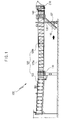
- FIG. 1 is a lateral view of a boarding bridge according to an exemplary embodiment of the present invention.
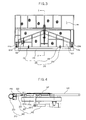
- FIG. 2 is an extended lateral view of a cab in FIG. 1 .
- FIG. 3 is a plan view of a floor of the cab.
- FIG. 4 is a lateral sectional view of the floor taken along line A-A' in FIG. 3 .
- FIG. 5 is a plan view of a minute approaching device.
- FIG. 6 is a lateral sectional view of a shock absorbing part.
- FIGS. 7 and 8 are lateral views which illustrate an operation process of the boarding bridge according to the present invention.
- FIG. 9 is a block diagram of the boarding bridge.
- a boarding bridge 100 includes a rotunda 110, a tunnel 120, a cab 140 and a minute approaching device 210 to form a passage between an airport building and aircraft to thereby enable passengers to get on the aircraft or a cargo to be loaded thereinto regardless of external weather conditions.
- the boarding bridge 100 further includes a shock absorbing part 230.
- the rotunda 110 supports the tunnel 120, and acts as a rotational shaft when the tunnel 120 rotates and acts as a supporting pillar when the tunnel 120 contracts and extends.
- the rotunda 110 may be extended and installed at an airport building or installed in an end part of a fixed tunnel 123 connected to the airport building as in FIG. 1 .
- the tunnel 120 forms a passage through which passengers move.
- the tunnel 120 includes the fixed tunnel 123 and contracting and extending tunnels 125a and 125b.
- the tunnel has a reference numeral 120 without being classified particularly.
- the contracting and extending tunnel 120 may change its length, direction and height.
- the tunnel 120 may include therein various equipment such as an air-conditioning and heating equipment for passengers' convenience.
- the tunnel 120 may move until an adjacent location as shown in FIG. 2 .
- a lift column 130 is coupled to the tunnel 120 and moves the tunnel 120 upwards and downwards to adjust a height of the tunnel 120. That is, the lift column 130 adjusts the height of the tunnel 120 so that a bottom of the cab 140 corresponds to a height of a gate provided in a body the aircraft in various sizes and heights.
- a wheel drive 133 which is attached to a lower part of the lift column 130 supplies a driving force to the tunnel 120 if a direction or a length of the tunnel 120 is changed.
- the length of the tunnel 120 may be changed by wire, chair or other various means as necessary.
- the reference numeral 137 refers to a service land and a stair which act as a passage to move from the outside of the tunnel 120 to the inside thereof.
- a major moving device which moves the boarding bridge 100 to a standby location and the adjacent location includes the wheel drive 133.
- a leveler 160 detects a height of aircraft and adjusts the height of the cab 140. If the height of the aircraft rises when the cab 140 contacts the aircraft for passengers to get off the aircraft, the leveler 160 detects the raised height of the aircraft and transmits the detection result to the controller 270. Then, the controller 270 controls the lift column 130 to raise the height of the tunnel 120. Then, the bottom of the cab 140 rises and its height becomes equal to the height of the gate of the aircraft in height. Thus, passengers may safely move between the aircraft and the boarding bridge 100.
- the canopy 170 seals the cab 140 and the aircraft so that the passage is not affected by external air.
- the canopy 170 is shaped like a bellows. Since the canopy 170 is shaped like a bellows, it may absorb shock on its own.
- a contact part of the boarding bridge 100 and the aircraft is left and right sides and an end of an upper side of the canopy 170. In the minute approaching device 210, the contact part of the boarding bridge 100 and the aircraft is the shock absorbing part 230 of the end part.
- a level maintaining device 180 is coupled to a lower part of the minute approaching device 210 and is supported by the fixed floor 145 to maintain a level of a moving floor 221.
- the level maintaining device 180 may include a mechanical lifting device unlike a pneumatic or hydraulic cylinder according to the exemplary embodiment.
- the cab 140 is coupled to an end part of the tunnel 120 and forms a passage between the tunnel 120 and the aircraft.
- the cab 140 includes the fixed floor 145 and the moving floor 221.
- the cab 140 further includes a cab rotating drive 151 which supplies a rotational force to the cab 140 rotating with regard to the tunnel 120.
- the cab 140 is provided in an end part of the boarding bridge 100 and secures a field of vision, and includes an operation room (not shown) to operate the boarding bridge 100.
- the fixed floor 145 includes a fixture which has a sufficient strength and forms a bottom of the passage in a lower part of the cab 140, and includes a moving floor panel 223 acting as a footing for passengers in an upper part thereof.
- a support 149 is provided in a lower part of the fixed floor 145 to support the minute approaching device 210.
- the minute approaching device 210 includes a minute moving part 220 and the shock absorbing part 230. As shown in FIG. 2 , the minute approaching device 210 is provided in an end part of the cab 140, and moves the cab 140 from the adjacent location to a contact location of the aircraft after the cab 140 completes moving from the standby location to the adjacent location by the movement of the tunnel 120.
- the minute moving part 220 is provided in a lower end part of the cab 140, and is supported by the fixed floor 145.
- the minute moving part 220 includes the moving floor 221 which has a sufficient strength for passengers to move, the minute drive 225 and a minute moving guide 227.
- the moving floor panel 223 is formed in an upper part of the moving floor 221 to act as a footing. As shown in FIG. 4 , the moving floor panel 223 partly overlaps the fixed floor panel 147. Even if the minute approaching device 210 moves and the moving floor panel 223 moves a little, the fixed floor panel 147 overlaps the moving floor panel 223 and forms a bottom.
- the minute approaching device 210 is moved by the minute drive 225 and the minute moving guide 227.
- a first side of the minute drive 225 is supported by the fixed floor 145 and a second side thereof is coupled with the moving floor 221 and supplies a driving force to move the moving floor 221.
- the minute drive 225 according to the present exemplary embodiment includes a power cylinder, but not limited thereto.
- the minute drive 225 may include a pneumatic or hydraulic cylinder, or other mechanism such as a rack and pinion having a motor.
- the minute moving guide 227 guides a movement of the minute approaching device 210.
- the minute moving guide 227 includes a bush 227a which is coupled to the fixed floor 145, and a guiding shaft 227a which is coupled to the inside of opposite bushes 227a and coupled to the moving floor 221 to slidably move. If the minute drive 225 applies a force to the moving floor 221, the guiding shaft 227a which is coupled to the moving floor 221 is guided by two bushes 227a of the fixed floor 145, and the moving floor 221 may move toward the body of the aircraft distant from the tunnel 120.
- the minute moving guide 227 may include a general bush, an LM guide and a rack and a pinion other than the guiding shaft 227a and the ball bush 227a.
- the minute approaching device 210 further includes a canopy clamp 224a which is provided in a lateral side thereof and is coupled to the canopy 170 moving along a canopy rail 224a of the fixed floor 145.
- the canopy 170 may move along with the movement of the minute approaching device 210.
- the shock absorbing part 230 is coupled to an end part of the minute approaching device 210 to absorb shock arising from the boarding bridge 100 or the aircraft and prevents transmission of the shock to the boarding bridge 100 or the aircraft.
- the shock absorbing part 230 contacts the aircraft and thus includes a material such as rubber not to damage the fuselage.
- the shock absorbing part 230 includes a main shock absorbing member 233 which is provided in the end part of the minute approaching device 210, and an auxiliary shock absorbing member 235 which is coupled to the minute moving part 220 and moves the main shock absorbing member 233.
- the main shock absorbing member 233 is shaped like a cylinder which is hollow inside. A section of the cylinder is deformed by a pressure of the minute drive 225 when contacting the fuselage.
- a minute moving sensor 229 which is provided in the cylinder detects the deformation. Then, the controller 270 controls the minute drive 225 not to press the minute moving part 220.
- a first side of the auxiliary shock absorbing member 235 is coupled to the fixed floor 145 and a second side thereof is coupled to the main shock absorbing member 233 to absorb a shock of the main shock absorbing member 233.
- the auxiliary shock absorbing member 235 includes an auxiliary spring 237 which absorbs shock, and a shock absorber guiding member 239 which guides a movement of the main shock absorbing member 233 according to contraction and extension of the auxiliary spring 237.
- the auxiliary spring 237 is coupled to a shock absorbing supporting member 241 which is shaped like an alphabet L and is supported by the fixed floor 145.
- the shock absorber guiding member 239 is shaped like a roller which is coupled to a shock absorbing member fixing member 243 provided between the auxiliary spring 237 and the main shock absorbing member 233 and moves along the shock absorbing supporting member 241.
- a weight of elements which are moved by the contact of the boarding bridge 100 and the aircraft is heavy.
- a weight of elements which are moved by a contact of the aircraft is significantly lighter than that in the conventional art since only the minute approaching device 210 and the canopy 170 move.
- the shock which arises from the contact of the aircraft and the boarding bridge 100 is reduced in proportion to moved elements.
- the shock which arises from the contact of the aircraft and the boarding bridge 100 may sharply be reduced.
- the shock absorbing part 230 includes a plurality of shock absorber members 233 and 235 and significantly reduces the shock arising from the movement of passengers. That is, the shock-absorbing part 230 may absorb shock arising from the main shock absorbing member 233 and the auxiliary shock absorbing member 235 to thereby increase the shock absorbing volume. Particularly, the shock absorbing part 230 has a configuration which efficiently responds to a heavy shock which arises momentarily from a long distance.
- damage to the boarding bridge 100 or to the aircraft during the contact thereof may be prevented and an operator may operate the boarding bridge 100 more comfortably.
- a safety accident may be prevented by a more comfortable and safe operation. Since the damage is prevented, the lifespan of the boarding bridge 100 may be extended. Passengers may move comfortably and stably.
- the shock absorbing part 230 has a double shock absorbing configuration, a space which is caused by a round body of the aircraft when the aircraft moves upwards or downwards may be prevented or reduced. Since the boarding bridge 100 is closely adhered to the aircraft, passengers may feel secure.
- the boarding bridge 100 is moved from the standby location as shown in FIG. 7 to the adjacent location as shown in FIG. 8 . That is, an operator of the boarding bridge 100 or the controller 270 operates or controls the wheel drive 133 to move the cab 140 from the standby location to the adjacent location which is a location adjacent to the aircraft (e.g., approximately 200mm distant from the aircraft).
- the controller 270 may control the wheel drive 133 or the lift column 130, which drives a length, a direction and a height of the tunnel 120, based on information transmitted from a sensor detecting the length of the tunnel 20, a sensor detecting the direction of the tunnel 120, a sensor detecting the height of the tunnel 120 and a sensor detecting a rotation angle of the cab 140.
- an operator of the boarding bridge 100 or the controller 270 controls the minute approaching device 210 to move a part of the cab 140 from the adjacent location to the contact location.
- the fixed floor 145 of the cab 140 does not move, and only the moving floor 221 moves. That is, a pressure is applied by the minute drive 225, the moving floor 221 is guided by the minute moving guide 227 and becomes distant from the tunnel 120. Then, the moving floor 221 which is provided in the lower part of the fixed floor panel 147 moves, and the main shock absorbing member 233 contacts the fuselage and is pressed by the minute drive 225. Then, the main shock absorbing member 233 which is shaped like a hollow cylinder is deformed.
- the controller 270 controls the minute drive 225 not to press the main shock absorbing member 233. If the minute moving part 220 moves, the canopy clamp 224a attached to the minute moving part 220 also moves. The canopy 170 then moves along the canopy rail 224a of the fixed floor 145. If the minute moving part 220 contacts the aircraft, the bellows of the canopy 170 unfolds and seals the cab 140 and the aircraft. If the leveler 160 detects rise or fall of the height of the gate in the aircraft, the controller 270 controls the lift column 130 to adjust the height of the tunnel 120 based on the detection signal. The level of the minute moving part 220 is controlled by the level maintaining device 180.
- the reference numeral 250 refers to a sensor and the reference numeral 260 refers to a driver.
- a minute approaching device instead of a tunnel, moves when the boarding bridge contacts the fuselage to thereby sharply reduce the weight of moved elements and reduce shock.
- the boarding bridge may be operated more comfortably since the weight of moved elements is lighter when the boarding bridge contacts the aircraft.
- a plurality of shock absorbing parts may absorb more shock and efficiently absorb momentary shock.
- the shock absorbing part may prevent or reduce a space between the aircraft and the boarding bridge even if the aircraft in round shape moves upwards or downwards. Thus, passengers may feel comfortable when boarding the aircraft.
Landscapes
- Engineering & Computer Science (AREA)
- Mechanical Engineering (AREA)
- Aviation & Aerospace Engineering (AREA)
- Architecture (AREA)
- Civil Engineering (AREA)
- Structural Engineering (AREA)
- Bridges Or Land Bridges (AREA)
- Vibration Dampers (AREA)
- Buildings Adapted To Withstand Abnormal External Influences (AREA)
Abstract
The present invention relates to a boarding bridge (100) with a minute approaching device and a shock absorbing part and an operation method thereof. The boarding bridge (100) comprises a rotunda (110); a tunnel (120) which contractably extends from the rotunda (110) and forms a passage; a cab (140) which is rotatably coupled to the tunnel (120) and connects the tunnel (120) and aircraft; a main moving device which moves the cab (140) by contraction and extension of the tunnel (120) from a standby location of the cab (140) and an adjacent location of the aircraft; and a minute approaching device which is provided in an end part of the cab (140) and minutely moves the end part of the cab (140) from the adjacent location to a contact location of the aircraft while the contraction and extension of the tunnel stops.
Accordingly, the boarding bridge (100) with the minute approaching device and the shock absorbing part and an operation method thereof according to the present invention enables an operator to operate the boarding bridge (100) more comfortably, prevents damage to the boarding bridge (100) or a fuselage, absorbs more shock and reduces or prevents a space between the boarding bridge (100) and the fuselage when the boarding bridge (100) moves upwards or downwards.
Description
- This application claims priority from Korean Patent Application No.
2009-114677, filed on November 11, 2009 - Apparatuses and methods consistent with the present invention relate to a boarding bridge with a minute approaching device and a shock absorbing part and an operation method thereof, and more particularly, to a boarding bridge with a minute approaching device and a shock absorbing part and an operation method thereof which improves an aircraft contacting device or a shock-absorbing device.
- Generally, a boarding bridge is installed to connect an airport building and aircraft to enable passengers to get on and off aircraft safely and conveniently without being affected by external environment such as weather conditions. Recently, airport buildings have been incorporated with modern and high technology, and aircraft have been upsized. Thus, the distance between aircraft and airport buildings becomes far from each other. The boarding bridge has a configuration that contacts, extends and moves depending on the size and location of a gate located in a fuselage.
- The boarding bridge includes a tunnel which forms a passage therein for passengers to move and has a plurality of partitioned paths that slidably moves to adjust a length thereof; a rotunda which functions as a rotational shaft or a pillar to enable the tunnel to rotate according to a location of aircraft; a lift column and a wheel drive which move the tunnel upwards and downwards or extends or reduces the tunnel depending on a size of aircraft and a location of a gate; and a cab which rotates with regard to the tunnel and contacts aircraft to form a passage between the tunnel and the aircraft. A canopy seals the cab and the fuselage not to be affected by external air. A shock absorbing device directly contacts the fuselage and absorbs shock arising from the aircraft or the cab, and fills up a gap between the boarding bridge and the aircraft, thereby allowing passengers or cargo to move more safely.
- To that end, it would be more preferable for the boarding bridge to approach the fuselage more softly and give less shock to such expensive aircraft. Even if small shock arises, it would be preferable to reduce the shock and absorb more shock. Further, it would be preferable to maintain a consistent space between an end of the boarding bridge and the fuselage when the boarding bridge moves upwards or downwards.
- Accordingly, it is an aspect of the present invention to provide a boarding bridge with a minute approaching device and a shock absorbing part and an operation method thereof which reduces shock arising from a contact of a fuselage by the boarding bridge and reduces or prevents a space when moving upwards or downward.
- Also, it is another aspect of the present invention to provide a boarding bridge and an operation method thereof which includes a minute approaching device, a shock-absorbing part and a space prevention device to operate the boarding bridge more comfortably.
- Further, it is another aspect of the present invention to provide a boarding bridge and an operation method thereof which includes a minute approaching device, a shock-absorbing part and a space prevention device to minimize damage to the boarding bridge and a fuselage.
- Further, it is another aspect of the present invention to provide a boarding bridge and an operation method thereof which includes a minute approaching device, a shock absorbing part and a space prevention device to absorb more shock and efficiently absorb momentary shock.
- Additional aspects and/or advantages of the present invention will be set forth in part in the description which follows and, in part, will be obvious from the description, or may be learned by practice of the present invention.
- The foregoing and/or other aspects of the present invention are also achieved by providing a boarding bridge comprising a rotunda; a tunnel which contractably extends from the rotunda and forms a passage; a cab which is rotatably coupled to the tunnel and connects the tunnel and aircraft; a main moving device which moves the cab by contraction and extension of the tunnel from a standby location of the cab and an adjacent location of the aircraft; and a minute approaching device which is provided in an end part of the cab and minutely moves the end part of the cab from the adjacent location to a contact location of the aircraft while the contraction and extension of the tunnel stops.
- According to an aspect of the invention, the main moving device comprises a wheel drive which is provided in a lower part of a lift column coupled to the tunnel and moving the tunnel upwards or downwards; and the minute approaching device comprises a fixed floor provided in a lower part of the cab toward the tunnel and a moving floor coupled in a direction facing the tunnel to move with regard to the fixed floor, and the minute approaching device moves the moving floor with regard to the fixed floor.
- According to another aspect of the invention, the minute approaching device comprises a minute drive whose first side is fixed to the fixed floor and a second side is fixed to the moving floor to supply a force moving the moving floor; and a minute moving guide which guides the moving floor while the moving floor is moved by the minute drive.
- According to another aspect of the invention, the boarding bridge further comprises a canopy clamp which is provided in a first side of the minute approaching device and coupled to a canopy that seals the cab and the fuselage to move along a movement of the minute approaching device.
- According to another aspect of the invention, the minute approaching device further comprises a shock absorbing member which prevents a transmission of shock arising from one of the boarding bridge and the aircraft to the other one of the boarding bridge and the aircraft, and the shock absorbing part comprises a main shock absorbing member which contacts the aircraft and absorbs shock, and an auxiliary shock absorbing member which is provided between the main shock absorbing member and the minute approaching device and absorbs shock.
- According to another aspect of the invention, the auxiliary shock absorbing member comprises an auxiliary spring which is coupled to the main shock absorbing member and absorbs shock, and a shock absorber guiding member which guides the main shock absorbing member and the auxiliary spring during a process of absorbing shock by the auxiliary spring.
- The foregoing and/or other aspects of the present invention are also achieved by providing a boarding bridge comprising a rotunda; a tunnel which contractably extends from the rotunda and forms a passage; a cab which is rotatably coupled to the tunnel and connects the tunnel and a fuselage; a shock absorbing part which is provided not to transmit a shock arising from one of the cab and the fuselage to the other one of the cab and the fuselage; and the shock absorbing part comprising a main shock absorbing member contacting the fuselage and absorbing shock, and an auxiliary shock absorbing member provided between the main shock absorbing member and the cab and absorbing shock.
- According to another aspect of the invention, the boarding bridge further comprises a main moving device which moves the cab by contraction and extension of the tunnel from a standby location of the cap to an adjacent location of the fuselage; and a minute approaching device which minutely moves the cab from the adjacent location to a contact location of the fuselage while the contraction and extension of the tunnel stops.
- The foregoing and/or other aspects of the present invention are also achieved by providing an operation method of a boarding bridge, the method comprising moving a cab by a main moving device of the boarding bridge from a standby location of the cab to an adjacent location of a fuselage by contraction and extension of the tunnel, wherein the boarding bridge comprises a rotunda, a tunnel contractably extending from the rotunda and forming a passage and the cab rotatably coupled to the tunnel and connecting the tunnel and the fuselage; and moving the cab minutely by a minute approaching device from the adjacent location to a contact location of the fuselage while the contraction and extension of the tunnel stops.
- According to another aspect of the invention, the method further comprises absorbing a shock by a main shock absorbing member which contacts the fuselage and prevents a transmission of a shock arising from one of the cab and the fuselage to the other one of the cab and the fuselage, and an auxiliary shock absorbing member which is provided between the main shock absorbing member and the minute approaching device and absorbs shock.
- The above and/or other aspects of the present invention will become apparent and more readily appreciated from the following description of the embodiments, taken in conjunction with the accompanying drawings of which:
- FIG. 1
- is a lateral view of a boarding bridge according to an exemplary embodiment of the present invention;
- FIG. 2
- is an extended lateral view of a cab in
FIG. 1 ; - FIG. 3
- is a plan view of a floor of the cab;
- FIG. 4
- is a lateral sectional view of the floor taken along line A-A' in
FIG. 3 ; - FIG. 5
- is a plan view of a minute approaching device;
- FIG. 6
- is a lateral sectional view of a shock absorbing part;
- FIGS. 7 and 8
- are lateral views which illustrate an operation process of the boarding bridge according to the present invention; and
- FIG. 9
- is a block diagram of the boarding bridge.
- Hereinafter, exemplary embodiments of the present invention will be described with reference to accompanying drawings, wherein like numerals refer to like elements and repetitive descriptions will be avoided as necessary.
- Hereinafter, a boarding bridge and an operation method thereof which includes a minute approaching device and a shock absorbing part according to the present invention will be described with reference to
FIGS. 1 to 9 . -
FIG. 1 is a lateral view of a boarding bridge according to an exemplary embodiment of the present invention.FIG. 2 is an extended lateral view of a cab inFIG. 1 .FIG. 3 is a plan view of a floor of the cab.FIG. 4 is a lateral sectional view of the floor taken along line A-A' inFIG. 3 .FIG. 5 is a plan view of a minute approaching device.FIG. 6 is a lateral sectional view of a shock absorbing part.FIGS. 7 and8 are lateral views which illustrate an operation process of the boarding bridge according to the present invention.FIG. 9 is a block diagram of the boarding bridge. - A
boarding bridge 100 according to the present invention includes arotunda 110, atunnel 120, acab 140 and aminute approaching device 210 to form a passage between an airport building and aircraft to thereby enable passengers to get on the aircraft or a cargo to be loaded thereinto regardless of external weather conditions. Theboarding bridge 100 further includes ashock absorbing part 230. - As shown in
FIGS. 1 ,7 and8 , therotunda 110 supports thetunnel 120, and acts as a rotational shaft when thetunnel 120 rotates and acts as a supporting pillar when thetunnel 120 contracts and extends. Therotunda 110 may be extended and installed at an airport building or installed in an end part of afixed tunnel 123 connected to the airport building as inFIG. 1 . - The
tunnel 120 forms a passage through which passengers move. Thetunnel 120 includes the fixedtunnel 123 and contracting and extendingtunnels reference numeral 120 without being classified particularly. The contracting and extendingtunnel 120 may change its length, direction and height. Thetunnel 120 may include therein various equipment such as an air-conditioning and heating equipment for passengers' convenience. Thetunnel 120 may move until an adjacent location as shown inFIG. 2 . - A
lift column 130 is coupled to thetunnel 120 and moves thetunnel 120 upwards and downwards to adjust a height of thetunnel 120. That is, thelift column 130 adjusts the height of thetunnel 120 so that a bottom of thecab 140 corresponds to a height of a gate provided in a body the aircraft in various sizes and heights. - A
wheel drive 133 which is attached to a lower part of thelift column 130 supplies a driving force to thetunnel 120 if a direction or a length of thetunnel 120 is changed. The length of thetunnel 120 may be changed by wire, chair or other various means as necessary. Thereference numeral 137 refers to a service land and a stair which act as a passage to move from the outside of thetunnel 120 to the inside thereof. According to the present exemplary embodiment, a major moving device which moves theboarding bridge 100 to a standby location and the adjacent location includes thewheel drive 133. - A
leveler 160 detects a height of aircraft and adjusts the height of thecab 140. If the height of the aircraft rises when thecab 140 contacts the aircraft for passengers to get off the aircraft, theleveler 160 detects the raised height of the aircraft and transmits the detection result to thecontroller 270. Then, thecontroller 270 controls thelift column 130 to raise the height of thetunnel 120. Then, the bottom of thecab 140 rises and its height becomes equal to the height of the gate of the aircraft in height. Thus, passengers may safely move between the aircraft and theboarding bridge 100. - The
canopy 170 seals thecab 140 and the aircraft so that the passage is not affected by external air. Thecanopy 170 is shaped like a bellows. Since thecanopy 170 is shaped like a bellows, it may absorb shock on its own. A contact part of theboarding bridge 100 and the aircraft is left and right sides and an end of an upper side of thecanopy 170. In theminute approaching device 210, the contact part of theboarding bridge 100 and the aircraft is theshock absorbing part 230 of the end part. - A
level maintaining device 180 is coupled to a lower part of theminute approaching device 210 and is supported by the fixedfloor 145 to maintain a level of a movingfloor 221. Thelevel maintaining device 180 may include a mechanical lifting device unlike a pneumatic or hydraulic cylinder according to the exemplary embodiment. - The
cab 140 is coupled to an end part of thetunnel 120 and forms a passage between thetunnel 120 and the aircraft. Thecab 140 includes the fixedfloor 145 and the movingfloor 221. Thecab 140 further includes acab rotating drive 151 which supplies a rotational force to thecab 140 rotating with regard to thetunnel 120. Thecab 140 is provided in an end part of theboarding bridge 100 and secures a field of vision, and includes an operation room (not shown) to operate theboarding bridge 100. - As shown in
FIGS. 3 and 4 , the fixedfloor 145 includes a fixture which has a sufficient strength and forms a bottom of the passage in a lower part of thecab 140, and includes a movingfloor panel 223 acting as a footing for passengers in an upper part thereof. A support 149 is provided in a lower part of the fixedfloor 145 to support theminute approaching device 210. - As shown in
FIGS. 1 to 6 , theminute approaching device 210 includes aminute moving part 220 and theshock absorbing part 230. As shown inFIG. 2 , theminute approaching device 210 is provided in an end part of thecab 140, and moves thecab 140 from the adjacent location to a contact location of the aircraft after thecab 140 completes moving from the standby location to the adjacent location by the movement of thetunnel 120. - The
minute moving part 220 is provided in a lower end part of thecab 140, and is supported by the fixedfloor 145. Theminute moving part 220 includes the movingfloor 221 which has a sufficient strength for passengers to move, theminute drive 225 and aminute moving guide 227. - The moving
floor panel 223 is formed in an upper part of the movingfloor 221 to act as a footing. As shown inFIG. 4 , the movingfloor panel 223 partly overlaps the fixedfloor panel 147. Even if theminute approaching device 210 moves and the movingfloor panel 223 moves a little, the fixedfloor panel 147 overlaps the movingfloor panel 223 and forms a bottom. - The
minute approaching device 210 is moved by theminute drive 225 and theminute moving guide 227. A first side of theminute drive 225 is supported by the fixedfloor 145 and a second side thereof is coupled with the movingfloor 221 and supplies a driving force to move the movingfloor 221. Theminute drive 225 according to the present exemplary embodiment includes a power cylinder, but not limited thereto. Alternatively, theminute drive 225 may include a pneumatic or hydraulic cylinder, or other mechanism such as a rack and pinion having a motor. Theminute moving guide 227 guides a movement of theminute approaching device 210. Theminute moving guide 227 according to the present exemplary embodiment includes abush 227a which is coupled to the fixedfloor 145, and a guidingshaft 227a which is coupled to the inside ofopposite bushes 227a and coupled to the movingfloor 221 to slidably move. If theminute drive 225 applies a force to the movingfloor 221, the guidingshaft 227a which is coupled to the movingfloor 221 is guided by twobushes 227a of the fixedfloor 145, and the movingfloor 221 may move toward the body of the aircraft distant from thetunnel 120. Theminute moving guide 227 may include a general bush, an LM guide and a rack and a pinion other than the guidingshaft 227a and theball bush 227a. - The
minute approaching device 210 further includes acanopy clamp 224a which is provided in a lateral side thereof and is coupled to thecanopy 170 moving along acanopy rail 224a of the fixedfloor 145. Thecanopy 170 may move along with the movement of theminute approaching device 210. - The
shock absorbing part 230 is coupled to an end part of theminute approaching device 210 to absorb shock arising from theboarding bridge 100 or the aircraft and prevents transmission of the shock to theboarding bridge 100 or the aircraft. Theshock absorbing part 230 contacts the aircraft and thus includes a material such as rubber not to damage the fuselage. Theshock absorbing part 230 includes a mainshock absorbing member 233 which is provided in the end part of theminute approaching device 210, and an auxiliaryshock absorbing member 235 which is coupled to theminute moving part 220 and moves the mainshock absorbing member 233. The mainshock absorbing member 233 is shaped like a cylinder which is hollow inside. A section of the cylinder is deformed by a pressure of theminute drive 225 when contacting the fuselage. If the mainshock absorbing member 233 is deformed too severely, aminute moving sensor 229 which is provided in the cylinder detects the deformation. Then, thecontroller 270 controls the minute drive 225 not to press theminute moving part 220. As shown inFIG. 6 , a first side of the auxiliaryshock absorbing member 235 is coupled to the fixedfloor 145 and a second side thereof is coupled to the mainshock absorbing member 233 to absorb a shock of the mainshock absorbing member 233. The auxiliaryshock absorbing member 235 includes anauxiliary spring 237 which absorbs shock, and a shockabsorber guiding member 239 which guides a movement of the mainshock absorbing member 233 according to contraction and extension of theauxiliary spring 237. Theauxiliary spring 237 is coupled to a shock absorbing supporting member 241 which is shaped like an alphabet L and is supported by the fixedfloor 145. The shockabsorber guiding member 239 is shaped like a roller which is coupled to a shock absorbingmember fixing member 243 provided between theauxiliary spring 237 and the mainshock absorbing member 233 and moves along the shock absorbing supporting member 241. - In the conventional art, if the
tunnel 120 moves, thelift column 130, thewheel drive 133 and thecab 140 move all and the end part of thecab 140 contacts the aircraft. That is, a weight of elements which are moved by the contact of theboarding bridge 100 and the aircraft is heavy. According to the present invention, however, a weight of elements which are moved by a contact of the aircraft is significantly lighter than that in the conventional art since only theminute approaching device 210 and thecanopy 170 move. Thus, the shock which arises from the contact of the aircraft and theboarding bridge 100 is reduced in proportion to moved elements. Thus, the shock which arises from the contact of the aircraft and theboarding bridge 100 may sharply be reduced. - The shock may also arise when passengers pass the
tunnel 120 and thecab 140 or move inside the aircraft not only when theboarding bridge 100 contacts the aircraft. According to the present invention, theshock absorbing part 230 includes a plurality ofshock absorber members part 230 may absorb shock arising from the mainshock absorbing member 233 and the auxiliaryshock absorbing member 235 to thereby increase the shock absorbing volume. Particularly, theshock absorbing part 230 has a configuration which efficiently responds to a heavy shock which arises momentarily from a long distance. - Thus, damage to the
boarding bridge 100 or to the aircraft during the contact thereof may be prevented and an operator may operate theboarding bridge 100 more comfortably. Also, a safety accident may be prevented by a more comfortable and safe operation. Since the damage is prevented, the lifespan of theboarding bridge 100 may be extended. Passengers may move comfortably and stably. As theshock absorbing part 230 has a double shock absorbing configuration, a space which is caused by a round body of the aircraft when the aircraft moves upwards or downwards may be prevented or reduced. Since theboarding bridge 100 is closely adhered to the aircraft, passengers may feel secure. That is, in the conventional art, when the aircraft moves upwards or downwards while theboarding bridge 100 contacts the aircraft, a space between theboarding bridge 100 and the aircraft becomes larger due to a round body of the aircraft, and passengers may miss their step due to the space. According to the present invention, however, such concern may be prevented. - With the foregoing configuration, an operation process of the
boarding bridge 100 according to the present invention will be described with reference toFIGS. 2 ,7 ,8 and9 . - The
boarding bridge 100 is moved from the standby location as shown inFIG. 7 to the adjacent location as shown inFIG. 8 . That is, an operator of theboarding bridge 100 or thecontroller 270 operates or controls thewheel drive 133 to move thecab 140 from the standby location to the adjacent location which is a location adjacent to the aircraft (e.g., approximately 200mm distant from the aircraft). During the process, thecontroller 270 may control thewheel drive 133 or thelift column 130, which drives a length, a direction and a height of thetunnel 120, based on information transmitted from a sensor detecting the length of the tunnel 20, a sensor detecting the direction of thetunnel 120, a sensor detecting the height of thetunnel 120 and a sensor detecting a rotation angle of thecab 140. - As shown in
FIGS. 2 ,8 and9 , an operator of theboarding bridge 100 or thecontroller 270 controls theminute approaching device 210 to move a part of thecab 140 from the adjacent location to the contact location. During this process, the fixedfloor 145 of thecab 140 does not move, and only the movingfloor 221 moves. That is, a pressure is applied by theminute drive 225, the movingfloor 221 is guided by theminute moving guide 227 and becomes distant from thetunnel 120. Then, the movingfloor 221 which is provided in the lower part of the fixedfloor panel 147 moves, and the mainshock absorbing member 233 contacts the fuselage and is pressed by theminute drive 225. Then, the mainshock absorbing member 233 which is shaped like a hollow cylinder is deformed. If theminute moving sensor 229 detects a predetermined pressure on the mainshock absorbing member 233 and transmits the detection result to thecontroller 270, thecontroller 270 controls the minute drive 225 not to press the mainshock absorbing member 233. If theminute moving part 220 moves, thecanopy clamp 224a attached to theminute moving part 220 also moves. Thecanopy 170 then moves along thecanopy rail 224a of the fixedfloor 145. If theminute moving part 220 contacts the aircraft, the bellows of thecanopy 170 unfolds and seals thecab 140 and the aircraft. If theleveler 160 detects rise or fall of the height of the gate in the aircraft, thecontroller 270 controls thelift column 130 to adjust the height of thetunnel 120 based on the detection signal. The level of theminute moving part 220 is controlled by thelevel maintaining device 180. Thereference numeral 250 refers to a sensor and thereference numeral 260 refers to a driver. - According to the present invention, a minute approaching device, instead of a tunnel, moves when the boarding bridge contacts the fuselage to thereby sharply reduce the weight of moved elements and reduce shock.
- Also, the boarding bridge may be operated more comfortably since the weight of moved elements is lighter when the boarding bridge contacts the aircraft.
- Further, as the weight of moved elements is lighter at the time of contact of the boarding bridge, damage to the boarding bridge or the fuselage which may arise during the contact process may be minimized.
- Further, as the weight of moved elements is lighter at the time of contact of the boarding bridge, safety accident may be prevented.
- Further, a plurality of shock absorbing parts may absorb more shock and efficiently absorb momentary shock.
- Further, the shock absorbing part may prevent or reduce a space between the aircraft and the boarding bridge even if the aircraft in round shape moves upwards or downwards. Thus, passengers may feel comfortable when boarding the aircraft. Although a few exemplary embodiments of the present invention have been shown and described, it will be appreciated by those skilled in the art that changes may be made in these exemplary embodiments without departing from the principles and spirit of the invention, the scope of which is defined in the appended claims and their equivalents.
Claims (11)
- A boarding bridge, comprising:a rotunda;a tunnel which contractably extends from the rotunda and forms a passage;a cab which is rotatably coupled to the tunnel and connects the tunnel and aircraft;a main moving device which moves the cab by contraction and extension of the tunnel from a standby location which the cab stands by to an adjacent location which the cap is adjacent of the aircraft; anda minute approaching device which is provided in an end part of the cab and minutely moves the end part of the cab from the adjacent location to a contact location of the aircraft while the contraction and extension of the tunnel stops.
- The boarding bridge according to claim 1, wherein the main moving device comprises a wheel drive which is provided in a lower part of a lift column coupled to the tunnel and moving the tunnel upwards or downwards; and
the minute approaching device comprises a fixed floor provided in a lower part of the cab toward the tunnel and a moving floor coupled in a direction facing the tunnel to move with regard to the fixed floor, and
the minute approaching device moves the moving floor with regard to the fixed floor. - The boarding bridge according to claim 2, wherein the minute approaching device comprises a minute drive whose first side is fixed to the fixed floor and a second side is fixed to the moving floor to supply a force moving the moving floor; and
a minute moving guide which guides the moving floor while the moving floor is moved by the minute drive. - The boarding bridge according to claim 1, further comprising a canopy clamp which is provided in a first side of the minute approaching device and coupled to a canopy that seals between the cab and a fuselage to move along a movement of the minute approaching device.
- The boarding bridge according to one of claims 1 , wherein the minute approaching device further comprises a shock absorbing member which prevents a transmission of shock arising from one of the boarding bridge and the aircraft to the other one of the boarding bridge and the aircraft, and
the shock absorbing part comprises a main shock absorbing member which contacts the aircraft and absorbs shock, and an auxiliary shock absorbing member which is provided between the main shock absorbing member and the minute approaching device and absorbs shock. - The boarding bridge according to claim 5, wherein the auxiliary shock absorbing member comprises an auxiliary spring which is coupled to the main shock absorbing member and absorbs shock, and a shock absorber guiding member which guides the main shock absorbing member and the auxiliary spring during a process of absorbing shock by the auxiliary spring.
- The boarding bridge according to one of claims 2 , wherein the minute approaching device further comprises a shock absorbing member which prevents a transmission of shock arising from one of the boarding bridge and the aircraft to the other one of the boarding bridge and the aircraft, and
the shock absorbing part comprises a main shock absorbing member which contacts the aircraft and absorbs shock, and an auxiliary shock absorbing member which is provided between the main shock absorbing member and the minute approaching device and absorbs shock. - A boarding bridge, comprising:a rotunda;a tunnel which contractably extends from the rotunda and forms a passage;a cab which is rotatably coupled to the tunnel and connects the tunnel and a fuselage;a shock absorbing part which is provided not to transmit a shock arising from one of the cab and the fuselage to the other one of the cab and the fuselage; andthe shock absorbing part comprising a main shock absorbing member contacting the fuselage and absorbing shock, and an auxiliary shock absorbing member provided between the main shock absorbing member and the cab and absorbing shock.
- The boarding bridge according to claim 8, further comprising a main moving device which moves the cab by contraction and extension of the tunnel from a standby location which the cap stands by to an adjacent location which the cap is adjacent of the fuselage; and a minute approaching device which minutely moves the cab from the adjacent location to a contact location of the fuselage while the contraction and extension of the tunnel is stops.
- An operation method of a boarding bridge, the method comprising:moving a cab by a main moving device of the boarding bridge from a standby location of the cab to an adjacent location of a fuselage by contraction and extension of the tunnel, wherein the boarding bridge comprises a rotunda, a tunnel contractably extending from the rotunda and forming a passage and the cab rotatably coupled to the tunnel and connecting the tunnel and the fuselage; andmoving the cab minutely by a minute approaching device from the adjacent location to a contact location of the fuselage while the contraction and extension of the tunnel stops.
- The method according to claim 10, further comprising absorbing a shock by a main shock absorbing member which contacts the fuselage and prevents a transmission of a shock arising from one of the cab and the fuselage to the other one of the cab and the fuselage, and an auxiliary shock absorbing member which is provided between the main shock absorbing member and the minute approaching device and absorbs shock.
Applications Claiming Priority (1)
| Application Number | Priority Date | Filing Date | Title |
|---|---|---|---|
| KR1020090114677A KR20110058023A (en) | 2009-11-25 | 2009-11-25 | Boarding bridge with fine access device and buffer part and its operation method |
Publications (1)
| Publication Number | Publication Date |
|---|---|
| EP2327630A2 true EP2327630A2 (en) | 2011-06-01 |
Family
ID=43608131
Family Applications (1)
| Application Number | Title | Priority Date | Filing Date |
|---|---|---|---|
| EP10003351A Withdrawn EP2327630A2 (en) | 2009-11-25 | 2010-03-29 | Boarding bridge with a minute approaching device and a shock absorbing part and operation method thereof |
Country Status (4)
| Country | Link |
|---|---|
| US (1) | US20110119842A1 (en) |
| EP (1) | EP2327630A2 (en) |
| KR (1) | KR20110058023A (en) |
| CN (1) | CN102069916A (en) |
Cited By (3)
| Publication number | Priority date | Publication date | Assignee | Title |
|---|---|---|---|---|
| EP2842874A4 (en) * | 2012-04-23 | 2015-12-09 | Korea Airports Corp | AIR CONDITIONING SYSTEM FOR PASSENGER BRIDGE BRIDGE, AND CONTROL SYSTEM THEREFOR |
| EP3006345A4 (en) * | 2013-06-07 | 2017-03-22 | Korea Airports Corporation | Height-adjustable rotunda-type boarding bridge |
| DE102019135461A1 (en) * | 2019-12-20 | 2021-06-24 | Airbus Operations Gmbh | Canopy assembly for a passenger bridge |
Families Citing this family (24)
| Publication number | Priority date | Publication date | Assignee | Title |
|---|---|---|---|---|
| CN102991694A (en) * | 2012-10-16 | 2013-03-27 | 蒂森克虏伯机场系统(中山)有限公司 | Multi-purpose boarding bridge floor |
| CN102975862B (en) * | 2012-11-23 | 2015-02-25 | 溧阳市科技开发中心 | Air conditioning device |
| CN102991719B (en) * | 2012-11-30 | 2015-07-15 | 溧阳市科技开发中心 | Awning device for boarding bridge |
| CN102991723B (en) * | 2012-11-30 | 2015-05-13 | 溧阳市科技开发中心 | Aerobridge manipulation method |
| CN102991722B (en) * | 2012-11-30 | 2015-08-05 | 溧阳市科技开发中心 | A kind of Passenger pathway manipulation method |
| CN102991721B (en) * | 2012-11-30 | 2015-08-05 | 溧阳市科技开发中心 | A kind of docking framework |
| CN102991715B (en) * | 2012-11-30 | 2015-08-05 | 溧阳市科技开发中心 | A kind of connecting bridge with air conditioner facility |
| US9284066B2 (en) | 2013-06-03 | 2016-03-15 | East Island Aviation Services, Inc. | Apparatus to interface a boarding bridge and a low doorsill airplane |
| KR101346068B1 (en) * | 2013-07-01 | 2013-12-31 | 주식회사 광림 | Vehicle comprising device for boarding of passanger ship |
| KR101618441B1 (en) | 2014-06-27 | 2016-05-09 | 현대로템 주식회사 | a Cabin bellows movement apparatus boarding bridge |
| GB2533818B (en) * | 2015-01-05 | 2021-03-03 | Bae Systems Plc | Mobile bridge apparatus |
| GB2533817A (en) | 2015-01-05 | 2016-07-06 | Bae Systems Plc | Mobile bridge module |
| WO2017152174A1 (en) * | 2016-03-04 | 2017-09-08 | Skygenex Inc. | Aerobridge providing multiple access points to aircraft vehicle |
| CN106628229B (en) * | 2016-08-31 | 2018-12-21 | 马宏 | The application of front frame posture aircraft carrying platform |
| CN106428610A (en) * | 2016-09-30 | 2017-02-22 | 美迪斯智能装备有限公司 | A safety control device for boarding bridge |
| KR101776036B1 (en) * | 2016-12-13 | 2017-09-07 | 한국공항공사 | Height adjusting apparatus for Passenger boading bridge |
| CN107054683B (en) * | 2017-06-01 | 2023-04-21 | 江苏瑞奇海力科技有限公司 | Automatic leveling detection system for vertical constant-pressure boarding bridge |
| NO344974B1 (en) * | 2017-09-22 | 2020-08-10 | Kongsberg Maritime As | Smart Gangway Tip |
| KR102188278B1 (en) * | 2018-12-11 | 2020-12-08 | 한국공항공사 | Boarding bridge and method for controlling boarding bridge |
| CN109987244B (en) * | 2019-04-23 | 2024-06-11 | 江苏上骐重工科技有限公司 | Mobile corridor vehicle |
| CN112046781B (en) * | 2020-09-11 | 2022-03-01 | 深圳中集天达空港设备有限公司 | Boarding bridge collision avoidance method and boarding bridge collision avoidance system |
| JP7213212B2 (en) * | 2020-09-25 | 2023-01-26 | 新明和工業株式会社 | passenger boarding bridge |
| KR102339666B1 (en) * | 2021-01-22 | 2021-12-14 | 주식회사 트라 | Docking ramp of boarding bridge |
| CN113204244B (en) * | 2021-04-23 | 2022-06-03 | 电子科技大学 | A boarding bridge docking method based on positioning and navigation |
Citations (1)
| Publication number | Priority date | Publication date | Assignee | Title |
|---|---|---|---|---|
| KR20090114677A (en) | 2008-04-30 | 2009-11-04 | 한전케이피에스 주식회사 | Transformer Heatsink Automatic Cleaner |
Family Cites Families (5)
| Publication number | Priority date | Publication date | Assignee | Title |
|---|---|---|---|---|
| GB8718300D0 (en) * | 1987-08-03 | 1987-09-09 | Gec Elliott Mech Handling | Airbridge |
| CN1106977C (en) * | 2000-03-10 | 2003-04-30 | 吴俊� | Boarding bridge with separated passenger way and bearing structure |
| CN2452888Y (en) * | 2000-10-24 | 2001-10-10 | 吴俊� | Moving means for passenger embarking bridge |
| ES2303798B1 (en) * | 2008-01-23 | 2009-08-27 | Thyssenkrupp Elevator (Es/Pbb) Ltd. | ENERGY TRANSMISSION SYSTEM AND DATA TO PASSENGER PASSENGER PASSENGERS FOR AIRCRAFT. |
| ES2310149B1 (en) * | 2008-02-18 | 2009-11-16 | Thyssenkrupp Elevator Innovation Center S.A. | EXTENSIBLE COVER FOR AIRCRAFT ACCESS PASSENGERS. |
-
2009
- 2009-11-25 KR KR1020090114677A patent/KR20110058023A/en not_active Application Discontinuation
-
2010
- 2010-01-07 US US12/683,534 patent/US20110119842A1/en not_active Abandoned
- 2010-03-29 CN CN2010101344855A patent/CN102069916A/en active Pending
- 2010-03-29 EP EP10003351A patent/EP2327630A2/en not_active Withdrawn
Patent Citations (1)
| Publication number | Priority date | Publication date | Assignee | Title |
|---|---|---|---|---|
| KR20090114677A (en) | 2008-04-30 | 2009-11-04 | 한전케이피에스 주식회사 | Transformer Heatsink Automatic Cleaner |
Cited By (4)
| Publication number | Priority date | Publication date | Assignee | Title |
|---|---|---|---|---|
| EP2842874A4 (en) * | 2012-04-23 | 2015-12-09 | Korea Airports Corp | AIR CONDITIONING SYSTEM FOR PASSENGER BRIDGE BRIDGE, AND CONTROL SYSTEM THEREFOR |
| US9976781B2 (en) | 2012-04-23 | 2018-05-22 | Korea Airports Corporation | Air-conditioning and heating system for passenger boarding bridge and control system therefor |
| EP3006345A4 (en) * | 2013-06-07 | 2017-03-22 | Korea Airports Corporation | Height-adjustable rotunda-type boarding bridge |
| DE102019135461A1 (en) * | 2019-12-20 | 2021-06-24 | Airbus Operations Gmbh | Canopy assembly for a passenger bridge |
Also Published As
| Publication number | Publication date |
|---|---|
| CN102069916A (en) | 2011-05-25 |
| US20110119842A1 (en) | 2011-05-26 |
| KR20110058023A (en) | 2011-06-01 |
Similar Documents
| Publication | Publication Date | Title |
|---|---|---|
| EP2327630A2 (en) | Boarding bridge with a minute approaching device and a shock absorbing part and operation method thereof | |
| EP2222590B1 (en) | Buffer arrangement and buffer stop of an elevator | |
| CN201065317Y (en) | Frame type radar antenna lifting device | |
| US7603736B2 (en) | Method for aligning a plurality of passenger boarding bridges | |
| WO2018055980A1 (en) | Passenger boarding bridge | |
| CN102741145B (en) | Double-decker lift installation | |
| EP3530605B1 (en) | Elevator car toe guard system | |
| WO2016038760A1 (en) | Passenger boarding bridge | |
| KR101422259B1 (en) | Engine test equipment | |
| US20070101520A1 (en) | Passenger boarding bridge stabilizing apparatus and method therefor | |
| KR20180017373A (en) | The pneumatic lifting device for transporting the heavy materials | |
| WO2018096773A1 (en) | Passenger boarding bridge | |
| US6704963B1 (en) | Failsafe support for height adjustable passenger loading bridges | |
| CN111170199B (en) | Air bag lifter for assembly of passenger car | |
| US10676333B2 (en) | Mobile lifting column with displacement system for lifting a vehicle, and lifting system and method therefor | |
| JP7497261B2 (en) | Jetway | |
| KR101382635B1 (en) | Pusher axle system | |
| JP4444055B2 (en) | Boarding bridge system | |
| CN215042802U (en) | Transponder height control system and track traffic system | |
| JP4324605B2 (en) | Boarding bridge | |
| JP5674421B2 (en) | Aircraft boarding bridge drive column movable mechanism | |
| KR100838228B1 (en) | Cargo lifter for building construction | |
| KR101232474B1 (en) | Spare tire mounting apparatus for vehicle and Spare tire mounting method for vehicle | |
| JP5416466B2 (en) | Boarding bridge | |
| CN222374099U (en) | Platform systems for elevator installations |
Legal Events
| Date | Code | Title | Description |
|---|---|---|---|
| PUAI | Public reference made under article 153(3) epc to a published international application that has entered the european phase |
Free format text: ORIGINAL CODE: 0009012 |
|
| AK | Designated contracting states |
Kind code of ref document: A2 Designated state(s): AT BE BG CH CY CZ DE DK EE ES FI FR GB GR HR HU IE IS IT LI LT LU LV MC MK MT NL NO PL PT RO SE SI SK SM TR |
|
| AX | Request for extension of the european patent |
Extension state: AL BA ME RS |
|
| STAA | Information on the status of an ep patent application or granted ep patent |
Free format text: STATUS: THE APPLICATION IS DEEMED TO BE WITHDRAWN |
|
| 18D | Application deemed to be withdrawn |
Effective date: 20121002 |