EP2325685B1 - Arc-shaped flexible printed circuit film type endoscope using imaging device with driving holes - Google Patents
Arc-shaped flexible printed circuit film type endoscope using imaging device with driving holes Download PDFInfo
- Publication number
- EP2325685B1 EP2325685B1 EP10250065.9A EP10250065A EP2325685B1 EP 2325685 B1 EP2325685 B1 EP 2325685B1 EP 10250065 A EP10250065 A EP 10250065A EP 2325685 B1 EP2325685 B1 EP 2325685B1
- Authority
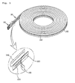
- EP
- European Patent Office
- Prior art keywords
- printed circuit
- circuit film
- driving
- arc
- shaped flexible
- Prior art date
- Legal status (The legal status is an assumption and is not a legal conclusion. Google has not performed a legal analysis and makes no representation as to the accuracy of the status listed.)
- Active
Links
Images



Classifications
-
- G—PHYSICS
- G02—OPTICS
- G02B—OPTICAL ELEMENTS, SYSTEMS OR APPARATUS
- G02B23/00—Telescopes, e.g. binoculars; Periscopes; Instruments for viewing the inside of hollow bodies; Viewfinders; Optical aiming or sighting devices
- G02B23/24—Instruments or systems for viewing the inside of hollow bodies, e.g. fibrescopes
- G02B23/2476—Non-optical details, e.g. housings, mountings, supports
- G02B23/2484—Arrangements in relation to a camera or imaging device
-
- G—PHYSICS
- G02—OPTICS
- G02B—OPTICAL ELEMENTS, SYSTEMS OR APPARATUS
- G02B23/00—Telescopes, e.g. binoculars; Periscopes; Instruments for viewing the inside of hollow bodies; Viewfinders; Optical aiming or sighting devices
- G02B23/24—Instruments or systems for viewing the inside of hollow bodies, e.g. fibrescopes
- G02B23/2476—Non-optical details, e.g. housings, mountings, supports
- G02B23/2492—Arrangements for use in a hostile environment, e.g. a very hot, cold or radioactive environment
-
- H—ELECTRICITY
- H04—ELECTRIC COMMUNICATION TECHNIQUE
- H04N—PICTORIAL COMMUNICATION, e.g. TELEVISION
- H04N23/00—Cameras or camera modules comprising electronic image sensors; Control thereof
Definitions
- the present invention relates generally to an industrial endoscope and, more particularly, to an arc-shaped flexible printed circuit film type endoscope using an imaging device with driving holes, in which the driving holes are formed at regular intervals in a longitudinal direction in the endoscope having a flexible printed circuit film connected to a head housing accommodating a charge coupled device (CCD) or complementary metal-oxide-semiconductor (CMOS) sensor as the imaging device, and interact with a driving device having a toothed part such as an intermittent gear or sprocket, thus allowing the endoscope to be precisely driven.
- CCD charge coupled device
- CMOS complementary metal-oxide-semiconductor
- a plurality of heat transfer tubes is mounted on the tube sheet of a secondary side of a steam generator installed in a nuclear power plant, with very narrow gaps formed between the heat transfer tubes.
- sludge or impurities may enter the gaps between the heat transfer tubes, thus causing damage to the heat transfer tubes.
- visual inspection is periodically conducted.
- the visual inspection is performed through endoscopy using an endoscope camera which is mounted to a micro robot or the like.
- Endoscopy is the non-destructive inspection method of visually inspecting the interior of a human body organ or an object without impairing the human body organ or the object, by inserting an insertion tube into the human body organ or the object.
- Endoscopes are typically classified into medical and industrial endoscopes according to the object to be inspected. Among them, the manufacture of the industrial endoscope is difficult because its insertion part is small and thin.
- the industrial endoscope includes an input-output unit for visually inspecting an object, a light source, and an insertion tube. Since most inspection instruments are too large to be inspected by an inspector, a lot of time, labor and expense are required.
- the industrial endoscope adopts an analogue method.
- photographs must be printed through chemical treatment, and the inspected result must be read via image equipment which is installed in an inspection site, so that there are restrictions of time and space.
- image equipment which is installed in an inspection site, so that there are restrictions of time and space.
- it is impossible to transmit data of the inspected result over a network it is impossible share the data in real time.
- an endoscope which has an industrial endoscope camera including an endoscope camera and a CCD sensor
- a belt or a chain having a cable therein has been proposed.
- the conventional endoscope is problematic in that the chain or belt is thick, so that it occupies a large space when rolled into a circular shape, and therefore it is difficult to mount the endoscope to a small space such as a robot so as to inspect the interior of a narrow heat transfer tube.
- the conventional belt- or circular cable-type endoscope camera is problematic in that when it is constructed to be very thin, it is too flexible, so that it is difficult to maintain strength when linearly extended. Further, the endoscope camera, the cable, an illumination part and other parts are integrally installed in the chain- or belt-type feeding means, so that a bending radius is large. Thus, it is difficult to mount the conventional endoscope to a narrow space such as a robot and to handle it.
- the remote inspection system includes a CMOS image sensor as an imaging device of a video camera.
- CMOS image sensor as an imaging device of a video camera.
- a photographing unit includes the CMOS sensor and the illumination part, so that it is possible to photograph and inspect a small space.
- a circuit means or a transmission means for processing or transmitting a photographed image cannot be formed on the spiral metal tube itself, the circuit means or the transmission means for processing or transmitting the photographed image must be provided separately from the spiral metal tube, thus inconveniencing a manufacturer.
- Korean Patent Appln No. 10-2008-79894 was filed on Aug. 14, 2008 by the inventor of the present invention and is entitled "Arc-shaped flexible printed circuit film type endoscope using imaging device”.
- the arc-shaped flexible printed circuit film type endoscope using the imaging device includes an image photographing means 10 and an object insertion means 20.
- the image photographing means 10 includes a head housing 13 to which an imaging device 11 having a lens 11a and an illumination means 12 are mounted, and photographs an image.
- the object insertion means 20 includes an arc-shaped flexible thin foil 21, an insulating adhesive film 22, a circuit film 23 and an insulating protective film 24 which are layered and inserted into the interior of an object which is to be inspected.
- the object insertion means 20 is connected at one end thereof to the image photographing means 10 and connected at the other end to a transmission cable 26 through a connector 25.
- the illumination means 12 comprises LED lamps, and is configured so that lamp supports 12b are inserted into corresponding support insertion grooves 13b of the head housing 13 in such a way that each LED lamp 12a mounted to the corresponding lamp support 12b is inserted into a corresponding lamp insertion hole 13a of the head housing 13, and thereby an LED terminal contact point formed on the back of each lamp support 12b is in contact with a terminal contact point formed on a side surface of the rear portion of the corresponding support insertion groove 13b.
- the head housing 13 includes a plurality of lamp insertion holes 13a which are formed in the upper and lower portions of the front end of the head housing 13.
- the plurality of support insertion grooves 13b is formed in the head housing 13 to communicate with the lamp insertion holes 13a.
- a window 13c is formed in the central portion of the front end of the head housing 13.
- An imaging device insertion hole 13d is formed in the middle portion of the head housing 13 in a longitudinal direction thereof to communicate with the window 13c.
- a terminal contact point of the imaging device 11 is formed on a side surface on the rear portion of the imaging device insertion hole 13d.
- a connection surface 13e is provided on the rear end of the head housing 13. Pin holes 13f are formed in an end of the connection surface 13e.
- the endoscope according to Korean Patent Appln. No. 10-2008-79894 constructed as described above is problematic in that the object insertion means 20 of the endoscope is driven between rollers 30 by frictional force acting between the rollers 30 which are rotated while being in close contact with each other, so that slippage may occur in a contact surface between the object insertion means 20 having the shape of a thin plate and the rollers 30, and thereby it is difficult to precisely control the driving of the endoscope.
- US-2003/0,169,419 discloses a flexible endoscope using an imaging device with driving holes, including image photographing means having a head housing to which an imaging device and illumination means are mounted and photographing an image, and object insertion means inserted into an object which is to be inspected, the object insertion means being connected at a first end thereof to the image photographing means and connected to a transmission cable, the flexible film type endoscope comprising:
- an arc-shaped flexible printed circuit film type endoscope using an imaging device with driving holes which includes an image photographing means having a head housing to which an imaging device and illumination means are mounted and photographing an image, and an object insertion means having an arc-shaped flexible thin foil, an insulating adhesive film, a circuit film and an insulating protective film which are layered and inserted into an object which is to be inspected.
- the object insertion means is connected at a first end thereof to the image photographing means and connected at a second end thereof to a transmission cable via a connector.
- the endoscope includes a plurality of driving holes which are formed at regular intervals in a longitudinal direction of the object insertion means, and a driving means rotating while being sequentially inserted into the driving holes, thus moving the object insertion means.
- the hereinafter described embodiments of the present invention provide an arc-shaped flexible printed circuit film type endoscope using an imaging device with driving holes, in which the driving holes are formed at regular intervals in a longitudinal direction in the flexible printed circuit film forming an object insertion means of the endoscope, and interact with a driving device having a toothed part such as an intermittent gear or sprocket, thus precisely controlling the movement of the endoscope into a small space.
- the hereinafter described embodiments of the present invention provide an arc-shaped flexible printed circuit film type endoscope using an imaging device with driving holes, in which a flexible printed circuit film is connected to a head housing accommodating a charge coupled device (CCD) or complementary metal-oxide-semiconductor (CMOS) sensor, so that the endoscope can be mounted in a small space such as a robot owing to a small bending radius to be conveniently handled in the small space, thus making it easy to inspect a narrow heat transfer tube or gaps formed between heat transfer tubes.
- CCD charge coupled device
- CMOS complementary metal-oxide-semiconductor
- the hereinafter described embodiments of the present invention provide an arc-shaped flexible printed circuit film type endoscope using an imaging device with driving holes, which utilizes a flexible printed circuit film so that a circuit means or a transmission means for processing or transmitting an image photographed by the imaging device are formed on the flexible printed circuit film, thus realizing a simple structure, therefore achieving high economic efficiency due to a reduction in the time and costs required to manufacture a product, and increasing the reliability of endoscopy because there is no possibility of failure or malfunction, and increasing the life-span of the endoscope such that it can be reliably used for a lengthy period of time.
- the arc-shaped flexible printed circuit film type endoscope using the imaging device with the driving holes shown in Figs. 5 and 6 includes an image photographing means 10 and an object insertion means 20.
- the image photographing means 10 includes a head housing to which an imaging device and an illumination means are mounted, and photographs an image.
- the object insertion means 20 includes an arc-shaped flexible thin foil, an insulating adhesive film, a circuit film and an insulating protective film which are layered and inserted into the interior of an object which is to be inspected.
- the object insertion means 20 is connected at one end thereof to the image photographing means 10 and connected at the other end to a transmission cable through a connector.
- the endoscope includes a plurality of driving holes 100 which are formed at regular intervals in the longitudinal direction of the object insertion means 20, and a driving means 200 which rotate while being sequentially inserted into the driving holes 100, thus moving the object insertion means 20.
- the plurality of driving holes 100 are formed at regular intervals along the central portion of the object insertion means 20 in the longitudinal direction thereof.
- a printed circuit film 101 is provided between both edges of the object insertion means 20 and the driving holes 100, an arc-shaped flexible thin foil 102 is attached to the back surface of the printed circuit film 101, and an insulating protective film 103 is attached to the front surface of the printed circuit film 101.
- the plurality of driving holes may be formed at regular intervals in a longitudinal direction between the central portion of the object insertion means 20 and both edges of the object insertion means 20, and the printed circuit film 101 may be provided on a portion having no driving hole.
- the driving means includes a driving roller 201 and a driven roller 202.
- the driving roller 201 is provided on one side of the object insertion means 20, and has a plurality of cylindrical protrusions 201a which are arranged at regular intervals along the outer circumference of the driving roller 201.
- the driven roller 202 is provided on the other side of the object insertion means 20 in such a way as to be in close contact with the driving roller 201.
- the image photographing means 10 which is provided on the head of the endoscope must be precisely pushed into a portion which is to be inspected.
- the endoscope of this invention rotates the driving roller 201 forwards at a precise rotating amount by a device having an additional control unit which is not shown in the drawings.
- the driven roller 202 which is in close contact with the driving roller 201 rotates along with the driving roller 201.
- the cylindrical protrusions 201a of the driving roller 201 are sequentially inserted into the driving holes 100 of the object insertion means 20 which is disposed between the driving roller 201 and the driven roller 202.
- the image photographing means 10 of the endoscope precisely moves forwards into the object which is to be inspected, and is inserted into the desired depth into the object.
- the driving roller 201 rotates backwards
- the image photographing means 10 of the endoscope precisely moves backwards from the object which is to be inspected, and is dislodged from the object.
- the arc-shaped flexible printed circuit film type endoscope uses an imaging device with driving holes, in which the driving holes are formed at regular intervals in a longitudinal direction in the flexible printed circuit film forming an object insertion means of the endoscope, and interact with a driving device having a toothed part such as an intermittent gear or sprocket, thus precisely controlling the movement of the endoscope into a small space, and in which a flexible printed circuit film is connected to a head housing accommodating a CCD or CMOS sensor, so that the endoscope can be mounted in a small space such as a robot owing to a small bending radius to be conveniently handled in the small space, thus making it easy to inspect a narrow heat transfer tube or gaps formed between heat transfer tubes, and which utilizes a flexible printed circuit film so that a circuit means or a transmission means for processing or transmitting an image photographed by the imaging device are formed on the flexible printed circuit film, thus realizing a simple structure, therefore achieving high economic efficiency due to a reduction in the time and costs required to manufacture
Landscapes
- Physics & Mathematics (AREA)
- Astronomy & Astrophysics (AREA)
- General Physics & Mathematics (AREA)
- Optics & Photonics (AREA)
- Engineering & Computer Science (AREA)
- Multimedia (AREA)
- Signal Processing (AREA)
- Instruments For Viewing The Inside Of Hollow Bodies (AREA)
- Endoscopes (AREA)
- Studio Devices (AREA)
Description
- The present invention relates generally to an industrial endoscope and, more particularly, to an arc-shaped flexible printed circuit film type endoscope using an imaging device with driving holes, in which the driving holes are formed at regular intervals in a longitudinal direction in the endoscope having a flexible printed circuit film connected to a head housing accommodating a charge coupled device (CCD) or complementary metal-oxide-semiconductor (CMOS) sensor as the imaging device, and interact with a driving device having a toothed part such as an intermittent gear or sprocket, thus allowing the endoscope to be precisely driven.
- Generally, a plurality of heat transfer tubes is mounted on the tube sheet of a secondary side of a steam generator installed in a nuclear power plant, with very narrow gaps formed between the heat transfer tubes. Here, sludge or impurities may enter the gaps between the heat transfer tubes, thus causing damage to the heat transfer tubes.
- Therefore, in order to prevent the heat transfer tubes from being damaged by the sludge or impurities, visual inspection is periodically conducted. The visual inspection is performed through endoscopy using an endoscope camera which is mounted to a micro robot or the like.
- Endoscopy is the non-destructive inspection method of visually inspecting the interior of a human body organ or an object without impairing the human body organ or the object, by inserting an insertion tube into the human body organ or the object.
- Endoscopes are typically classified into medical and industrial endoscopes according to the object to be inspected. Among them, the manufacture of the industrial endoscope is difficult because its insertion part is small and thin.
- Thus, in Korea, the industrial endoscope has not been researched and developed nor has it come onto the market yet. The supply of most endoscopes depends on imports.
- The industrial endoscope includes an input-output unit for visually inspecting an object, a light source, and an insertion tube. Since most inspection instruments are too large to be inspected by an inspector, a lot of time, labor and expense are required.
- Further, the industrial endoscope adopts an analogue method. Thus, in order to store photographed images, photographs must be printed through chemical treatment, and the inspected result must be read via image equipment which is installed in an inspection site, so that there are restrictions of time and space. Further, since it is impossible to transmit data of the inspected result over a network, it is impossible share the data in real time.
- In consideration of these aspects, as the conventional industrial endoscope which has been used to visually inspect the heat transfer tubes, an endoscope which has an industrial endoscope camera (including an endoscope camera and a CCD sensor) and a belt or a chain having a cable therein has been proposed.
- The conventional endoscope is problematic in that the chain or belt is thick, so that it occupies a large space when rolled into a circular shape, and therefore it is difficult to mount the endoscope to a small space such as a robot so as to inspect the interior of a narrow heat transfer tube.
- Further, the conventional belt- or circular cable-type endoscope camera is problematic in that when it is constructed to be very thin, it is too flexible, so that it is difficult to maintain strength when linearly extended. Further, the endoscope camera, the cable, an illumination part and other parts are integrally installed in the chain- or belt-type feeding means, so that a bending radius is large. Thus, it is difficult to mount the conventional endoscope to a narrow space such as a robot and to handle it.
- Meanwhile, in order to photograph a small space, there has been proposed Japanese Patent Laid-Open Publication No.
2006-319401 - The remote inspection system includes a CMOS image sensor as an imaging device of a video camera. By manipulating a power supply for a video camera and a white LED which is connected in a conduction state through a flexible spiral metal tube to an inspection head having the white LED for illumination, the remote inspection system photographs a narrow space.
- Thus, a photographing unit includes the CMOS sensor and the illumination part, so that it is possible to photograph and inspect a small space. However, since a circuit means or a transmission means for processing or transmitting a photographed image cannot be formed on the spiral metal tube itself, the circuit means or the transmission means for processing or transmitting the photographed image must be provided separately from the spiral metal tube, thus inconveniencing a manufacturer.
- In order to solve the problems occurring in the conventional industrial endoscope, Korean Patent Appln No.
10-2008-79894 was filed on Aug. 14, 2008 - As shown in
FIGS. 1 to 3 , the arc-shaped flexible printed circuit film type endoscope using the imaging device according to the cited document includes an image photographing means 10 and an object insertion means 20. The image photographing means 10 includes ahead housing 13 to which animaging device 11 having alens 11a and an illumination means 12 are mounted, and photographs an image. The object insertion means 20 includes an arc-shaped flexiblethin foil 21, an insulatingadhesive film 22, acircuit film 23 and an insulatingprotective film 24 which are layered and inserted into the interior of an object which is to be inspected. The object insertion means 20 is connected at one end thereof to the image photographing means 10 and connected at the other end to atransmission cable 26 through aconnector 25. The illumination means 12 comprises LED lamps, and is configured so thatlamp supports 12b are inserted into correspondingsupport insertion grooves 13b of thehead housing 13 in such a way that eachLED lamp 12a mounted to thecorresponding lamp support 12b is inserted into a correspondinglamp insertion hole 13a of thehead housing 13, and thereby an LED terminal contact point formed on the back of eachlamp support 12b is in contact with a terminal contact point formed on a side surface of the rear portion of the correspondingsupport insertion groove 13b. Further, thehead housing 13 includes a plurality oflamp insertion holes 13a which are formed in the upper and lower portions of the front end of thehead housing 13. The plurality ofsupport insertion grooves 13b is formed in thehead housing 13 to communicate with thelamp insertion holes 13a. Awindow 13c is formed in the central portion of the front end of thehead housing 13. An imagingdevice insertion hole 13d is formed in the middle portion of thehead housing 13 in a longitudinal direction thereof to communicate with thewindow 13c. A terminal contact point of theimaging device 11 is formed on a side surface on the rear portion of the imagingdevice insertion hole 13d. Aconnection surface 13e is provided on the rear end of thehead housing 13.Pin holes 13f are formed in an end of theconnection surface 13e. The image photographing means 10 and the object insertion means 20 are connected to each other via alocking part 14 andlocking pins 15. - However, as shown in
FIG. 4 , the endoscope according to Korean Patent Appln. No.10-2008-79894 rollers 30 by frictional force acting between therollers 30 which are rotated while being in close contact with each other, so that slippage may occur in a contact surface between the object insertion means 20 having the shape of a thin plate and therollers 30, and thereby it is difficult to precisely control the driving of the endoscope. -
US-2003/0,169,419 discloses a flexible endoscope using an imaging device with driving holes, including image photographing means having a head housing to which an imaging device and illumination means are mounted and photographing an image, and object insertion means inserted into an object which is to be inspected, the object insertion means being connected at a first end thereof to the image photographing means and connected to a transmission cable, the flexible film type endoscope comprising: - a plurality of driving holes formed at regular intervals in a longitudinal direction of the object insertion means; and
- driving means rotating while being sequentially inserted into the driving holes, thus moving the object insertion means.
- According to the present invention, there is provided an arc-shaped flexible printed circuit film type endoscope using an imaging device with driving holes, which includes an image photographing means having a head housing to which an imaging device and illumination means are mounted and photographing an image, and an object insertion means having an arc-shaped flexible thin foil, an insulating adhesive film, a circuit film and an insulating protective film which are layered and inserted into an object which is to be inspected. The object insertion means is connected at a first end thereof to the image photographing means and connected at a second end thereof to a transmission cable via a connector. The endoscope includes a plurality of driving holes which are formed at regular intervals in a longitudinal direction of the object insertion means, and a driving means rotating while being sequentially inserted into the driving holes, thus moving the object insertion means.
- The hereinafter described embodiments of the present invention provide an arc-shaped flexible printed circuit film type endoscope using an imaging device with driving holes, in which the driving holes are formed at regular intervals in a longitudinal direction in the flexible printed circuit film forming an object insertion means of the endoscope, and interact with a driving device having a toothed part such as an intermittent gear or sprocket, thus precisely controlling the movement of the endoscope into a small space.
- The hereinafter described embodiments of the present invention provide an arc-shaped flexible printed circuit film type endoscope using an imaging device with driving holes, in which a flexible printed circuit film is connected to a head housing accommodating a charge coupled device (CCD) or complementary metal-oxide-semiconductor (CMOS) sensor, so that the endoscope can be mounted in a small space such as a robot owing to a small bending radius to be conveniently handled in the small space, thus making it easy to inspect a narrow heat transfer tube or gaps formed between heat transfer tubes.
- The hereinafter described embodiments of the present invention provide an arc-shaped flexible printed circuit film type endoscope using an imaging device with driving holes, which utilizes a flexible printed circuit film so that a circuit means or a transmission means for processing or transmitting an image photographed by the imaging device are formed on the flexible printed circuit film, thus realizing a simple structure, therefore achieving high economic efficiency due to a reduction in the time and costs required to manufacture a product, and increasing the reliability of endoscopy because there is no possibility of failure or malfunction, and increasing the life-span of the endoscope such that it can be reliably used for a lengthy period of time.
- The above and other features and advantages of the present invention will be more clearly understood from the following detailed description of embodiments of the present invention given with reference to the accompanying drawings, in which:
-
FIG. 1 is a perspective view illustrating a conventional arc-shaped flexible printed circuit film type endoscope using an imaging device; -
FIG. 2 is an exploded perspective view depicting the important parts of the conventional arc-shaped flexible printed circuit film type endoscope using the imaging device; -
FIG. 3 is a view illustrating an object insertion means of the conventional endoscope; -
FIG. 4 is a view illustrating a driving state using a driving means of the conventional endoscope; -
FIG. 5 is a perspective view illustrating an arc-shaped flexible printed circuit film type endoscope using an imaging device with driving holes; and -
FIG. 6 is a perspective view illustrating a driving means of the arc-shaped flexible printed circuit film type endoscope using the imaging device with the driving holes. - Hereinafter, an arc-shaped flexible printed circuit film type endoscope using an imaging device with driving holes will be described.
- The arc-shaped flexible printed circuit film type endoscope using the imaging device with the driving holes shown in
Figs. 5 and6 includes an image photographing means 10 and an object insertion means 20. The image photographing means 10 includes a head housing to which an imaging device and an illumination means are mounted, and photographs an image. The object insertion means 20 includes an arc-shaped flexible thin foil, an insulating adhesive film, a circuit film and an insulating protective film which are layered and inserted into the interior of an object which is to be inspected. The object insertion means 20 is connected at one end thereof to the image photographing means 10 and connected at the other end to a transmission cable through a connector. The endoscope includes a plurality ofdriving holes 100 which are formed at regular intervals in the longitudinal direction of the object insertion means 20, and a driving means 200 which rotate while being sequentially inserted into thedriving holes 100, thus moving the object insertion means 20. - The plurality of
driving holes 100 are formed at regular intervals along the central portion of the object insertion means 20 in the longitudinal direction thereof. A printedcircuit film 101 is provided between both edges of the object insertion means 20 and thedriving holes 100, an arc-shaped flexiblethin foil 102 is attached to the back surface of the printedcircuit film 101, and an insulatingprotective film 103 is attached to the front surface of the printedcircuit film 101. - Further, the plurality of driving holes may be formed at regular intervals in a longitudinal direction between the central portion of the object insertion means 20 and both edges of the object insertion means 20, and the printed
circuit film 101 may be provided on a portion having no driving hole. - Further, the driving means includes a driving
roller 201 and a drivenroller 202. The drivingroller 201 is provided on one side of the object insertion means 20, and has a plurality ofcylindrical protrusions 201a which are arranged at regular intervals along the outer circumference of the drivingroller 201. The drivenroller 202 is provided on the other side of the object insertion means 20 in such a way as to be in close contact with the drivingroller 201. - The operation of the arc-shaped flexible printed circuit film type endoscope using the imaging device with the driving holes constructed as described above will be described below.
- When a user desires to observe narrow gaps between heat transfer tubes using the endoscope of the present invention, the image photographing means 10 which is provided on the head of the endoscope must be precisely pushed into a portion which is to be inspected. To this end, the endoscope of this invention rotates the driving
roller 201 forwards at a precise rotating amount by a device having an additional control unit which is not shown in the drawings. - Thereby, the driven
roller 202 which is in close contact with the drivingroller 201 rotates along with the drivingroller 201. At this time, thecylindrical protrusions 201a of the drivingroller 201 are sequentially inserted into the drivingholes 100 of the object insertion means 20 which is disposed between the drivingroller 201 and the drivenroller 202. Thus, as the drivingroller 201 rotates forwards, the image photographing means 10 of the endoscope precisely moves forwards into the object which is to be inspected, and is inserted into the desired depth into the object. Meanwhile, as the drivingroller 201 rotates backwards, the image photographing means 10 of the endoscope precisely moves backwards from the object which is to be inspected, and is dislodged from the object. - As described above, the arc-shaped flexible printed circuit film type endoscope uses an imaging device with driving holes, in which the driving holes are formed at regular intervals in a longitudinal direction in the flexible printed circuit film forming an object insertion means of the endoscope, and interact with a driving device having a toothed part such as an intermittent gear or sprocket, thus precisely controlling the movement of the endoscope into a small space, and in which a flexible printed circuit film is connected to a head housing accommodating a CCD or CMOS sensor, so that the endoscope can be mounted in a small space such as a robot owing to a small bending radius to be conveniently handled in the small space, thus making it easy to inspect a narrow heat transfer tube or gaps formed between heat transfer tubes, and which utilizes a flexible printed circuit film so that a circuit means or a transmission means for processing or transmitting an image photographed by the imaging device are formed on the flexible printed circuit film, thus realizing a simple structure, therefore achieving high economic efficiency due to a reduction in the time and costs required to manufacture a product, and increasing the reliability of endoscopy because there is no possibility of failure or malfunction, and increasing the life-span of the endoscope such that it can be reliably used for a lengthy period of time.
- Although the preferred embodiment of the present invention has been disclosed for illustrative purposes, those skilled in the art will appreciate that various modifications, additions and substitutions are possible, without departing from the scope of the invention as defined in the accompanying claims.
Claims (4)
- An arc-shaped flexible printed circuit film type endoscope using an imaging device (11) with driving holes (100), including image photographing means (10) having a head housing (13) to which an imaging device (11) and illumination means (12) are mounted and photographing an image, and object insertion means (20) having an arc-shaped flexible thin foil (21), an insulating adhesive film (22), a circuit film (23) and an insulating protective film (24) which are layered and inserted into an object which is to be inspected, the object insertion means (20) being connected at a first end thereof to the image photographing means (10) and connected at a second end thereof to a transmission cable (26) via a connector (25), the arc-shaped flexible printed circuit film type endoscope comprising:a plurality of driving holes (100) formed at regular intervals in a longitudinal direction of the object insertion means (20); anddriving means (201, 202) rotating while being sequentially inserted into the driving holes, thus moving the object insertion means (20).
- The arc-shaped flexible printed circuit film type endoscope as set forth in claim 1, wherein the plurality of driving holes (100) are formed at regular intervals along a central portion of the object insertion means (20) in the longitudinal direction thereof, a printed circuit film (101) is provided between both edges of the object insertion means and the driving holes (100), an arc-shaped flexible thin foil (102) is attached to a back surface of the printed circuit film (101), and an insulating protective film (103) is attached to a front surface of the printed circuit film (101).
- The arc-shaped flexible printed circuit film type endoscope as set forth in claim 1 or 2, wherein the plurality of driving holes (100) are formed at regular intervals in the longitudinal direction between a central portion of the object insertion means (20) and both edges of the object insertion means (20), and a printed circuit film (101) is provided on a portion having no driving hole.
- The arc-shaped flexible printed circuit film type endoscope as set forth in any one of the preceding claims, wherein the driving means (201) comprises:a driving roller provided on a first side of the object insertion means (20) and having a plurality of cylindrical protrusions (201a) arranged at regular intervals along an outer circumference of the driving roller (201); anda driven roller (202) provided on a second side of the object insertion means (20) in such a way as to be in close contact with the driving roller (201).
Applications Claiming Priority (1)
| Application Number | Priority Date | Filing Date | Title |
|---|---|---|---|
| KR1020090111959A KR101077562B1 (en) | 2009-11-19 | 2009-11-19 | Arc-shaped flexible printed circuit film type endoscope using imaging device with driving holes |
Publications (2)
| Publication Number | Publication Date |
|---|---|
| EP2325685A1 EP2325685A1 (en) | 2011-05-25 |
| EP2325685B1 true EP2325685B1 (en) | 2014-09-17 |
Family
ID=42223438
Family Applications (1)
| Application Number | Title | Priority Date | Filing Date |
|---|---|---|---|
| EP10250065.9A Active EP2325685B1 (en) | 2009-11-19 | 2010-01-15 | Arc-shaped flexible printed circuit film type endoscope using imaging device with driving holes |
Country Status (4)
| Country | Link |
|---|---|
| US (1) | US8419615B2 (en) |
| EP (1) | EP2325685B1 (en) |
| JP (1) | JP4929361B2 (en) |
| KR (1) | KR101077562B1 (en) |
Families Citing this family (12)
| Publication number | Priority date | Publication date | Assignee | Title |
|---|---|---|---|---|
| JP5372644B2 (en) * | 2009-07-30 | 2013-12-18 | オリンパス株式会社 | Endoscope |
| US8485967B2 (en) * | 2010-03-31 | 2013-07-16 | Fujifilm Corporation | Endoscopic imaging device and endoscope apparatus having a configuration to prevent condensation |
| KR20120073887A (en) * | 2010-12-27 | 2012-07-05 | 삼성전자주식회사 | Image processing apparatus and method for porcessing image thereof |
| US20130162767A1 (en) * | 2011-12-22 | 2013-06-27 | Himax Imaging Limited | Endoscope and wireless transmission system thereof |
| US20130162789A1 (en) * | 2011-12-22 | 2013-06-27 | Himax Imaging Limited | Endoscope with a light source |
| KR101860275B1 (en) * | 2017-12-11 | 2018-05-21 | 한전케이피에스 주식회사 | Endoscope unit |
| CN108106997A (en) * | 2017-12-28 | 2018-06-01 | 中广核研究院有限公司 | Overhanging detection device and its overhanging loading device |
| CN108098791B (en) * | 2017-12-28 | 2024-03-26 | 中广核研究院有限公司 | Special-shaped section cantilever arm and cantilever detection mechanism |
| KR102013073B1 (en) * | 2018-10-15 | 2019-08-21 | 한전케이피에스 주식회사 | Endoscope conveyance device, endoscopic unit and remote inspection apparatus |
| KR102064115B1 (en) * | 2019-05-07 | 2020-02-11 | 한전케이피에스 주식회사 | Flexible printed circuit board and endoscopic inspection apparatus comprising the same |
| CN111580573B (en) * | 2020-05-28 | 2021-05-07 | 北京中农绿源工程技术有限公司 | Greenhouse monitoring system for facility agriculture |
| KR102205484B1 (en) * | 2020-08-11 | 2021-01-20 | 한전케이피에스 주식회사 | Gear-driven endoscopic apparatus |
Family Cites Families (15)
| Publication number | Priority date | Publication date | Assignee | Title |
|---|---|---|---|---|
| US4586079A (en) * | 1983-10-07 | 1986-04-29 | Westinghouse Electric Corp. | Fiberscope delivery system |
| JPH067817B2 (en) * | 1986-02-27 | 1994-02-02 | 株式会社町田製作所 | Endoscope with built-in solid-state image sensor |
| US5341406A (en) * | 1987-03-18 | 1994-08-23 | Electric Power Research Institute, Inc. | Sliding lance guide flexible lance system |
| EP0460009B1 (en) | 1989-02-24 | 1994-10-05 | Autoliv-Kolb GmbH & Co. | Automatic safety belt reel |
| JPH07327923A (en) * | 1994-06-02 | 1995-12-19 | Olympus Optical Co Ltd | Endoscope system |
| US6142930A (en) * | 1997-01-13 | 2000-11-07 | Asahi Kogaku Kogyo Kabushiki Kaisha | Electronic endoscope having compact construction |
| WO1998035607A1 (en) * | 1997-02-13 | 1998-08-20 | Matsushita Electric Industrial Co., Ltd. | Endoscope, method of manufacturing the same, and inserting member |
| US6595913B2 (en) * | 2000-09-07 | 2003-07-22 | Fuji Photo Optical Co., Ltd. | Cable structure in electronic endoscope |
| EP2410324A3 (en) * | 2002-01-14 | 2012-04-25 | R. Brooks Associates, Inc. | Device for remote inspection of steam or cleaning of steam generator tubes |
| JP3668480B2 (en) * | 2003-03-06 | 2005-07-06 | オリンパス株式会社 | Imaging device |
| KR200339210Y1 (en) * | 2003-10-13 | 2004-01-24 | 지문수 | Belt type screw supply skein roll |
| US7300397B2 (en) * | 2004-07-29 | 2007-11-27 | C2C Cure, Inc. | Endoscope electronics assembly |
| JP2006319401A (en) * | 2005-05-10 | 2006-11-24 | Tech Pipe Co Ltd | Device for remote inspection and operation |
| JP2008135894A (en) | 2006-11-28 | 2008-06-12 | Nippon Seiki Co Ltd | Visual sensor device |
| KR100960262B1 (en) * | 2008-08-14 | 2010-06-07 | 한전케이피에스 주식회사 | Shape-Flexible Thin-Film Type Endoscope Using Imaging Device |
-
2009
- 2009-11-19 KR KR1020090111959A patent/KR101077562B1/en active Active
-
2010
- 2010-01-15 EP EP10250065.9A patent/EP2325685B1/en active Active
- 2010-01-29 JP JP2010018528A patent/JP4929361B2/en active Active
- 2010-01-29 US US12/696,953 patent/US8419615B2/en active Active
Also Published As
| Publication number | Publication date |
|---|---|
| EP2325685A1 (en) | 2011-05-25 |
| JP4929361B2 (en) | 2012-05-09 |
| KR101077562B1 (en) | 2011-10-28 |
| US8419615B2 (en) | 2013-04-16 |
| US20110118548A1 (en) | 2011-05-19 |
| JP2011107670A (en) | 2011-06-02 |
| KR20110055087A (en) | 2011-05-25 |
Similar Documents
| Publication | Publication Date | Title |
|---|---|---|
| US8419615B2 (en) | Arc-shaped flexible printed circuit film type endoscope using imaging device with driving holes | |
| EP2154557B1 (en) | Arc-shaped flexible printed circuit film type endoscope using imaging device | |
| US5239983A (en) | Connector apparatus for endoscope | |
| EP2324754A1 (en) | Insertion section of endoscope | |
| CN109963489B (en) | Endoscope head and endoscope provided with endoscope head | |
| RU2444273C2 (en) | Curving part of endoscope | |
| WO2008041809A1 (en) | Capsule type endoscope device | |
| WO2013132681A1 (en) | Image-capturing unit for endoscope | |
| US20130310646A1 (en) | Driving force transmission device for endoscope and auxiliary thrust device comprising thereof | |
| JPWO2019031018A1 (en) | Endoscope | |
| JP5112108B2 (en) | Capsule type endoscope camera and endoscope system | |
| JP4802056B2 (en) | In-pipe inspection camera device | |
| US10110824B2 (en) | Insertion device | |
| US20070197860A1 (en) | Endoscope inserting section with case, and method for removing endoscope inserting section | |
| CN111048222A (en) | Endoscope conveying device, endoscope unit and remote inspection device | |
| CN103648357A (en) | Medical apparatus | |
| US10299659B2 (en) | Insertion instrument and insertion device | |
| JP2009247666A (en) | Light source device for endoscope | |
| JP2007159642A (en) | Capsule type endoscope camera | |
| US9363434B2 (en) | Lens barrel and lens unit | |
| JPH11160629A (en) | Method for inserting endoscope to be inserted into pipe and endoscope device | |
| WO2021077240A1 (en) | Endoscope host and endoscope device for intelligently detecting organs | |
| JP5275541B2 (en) | Endoscope device | |
| JP4987353B2 (en) | ENDOSCOPE ADAPTER, ENDOSCOPE ADAPTER MANUFACTURING METHOD, AND ENDOSCOPE DEVICE | |
| JP2991468B2 (en) | Endoscope connector device |
Legal Events
| Date | Code | Title | Description |
|---|---|---|---|
| PUAI | Public reference made under article 153(3) epc to a published international application that has entered the european phase |
Free format text: ORIGINAL CODE: 0009012 |
|
| 17P | Request for examination filed |
Effective date: 20100203 |
|
| AK | Designated contracting states |
Kind code of ref document: A1 Designated state(s): AT BE BG CH CY CZ DE DK EE ES FI FR GB GR HR HU IE IS IT LI LT LU LV MC MK MT NL NO PL PT RO SE SI SK SM TR |
|
| AX | Request for extension of the european patent |
Extension state: AL BA RS |
|
| RIC1 | Information provided on ipc code assigned before grant |
Ipc: G02B 23/24 20060101AFI20131219BHEP Ipc: G21C 17/003 20060101ALI20131219BHEP |
|
| GRAP | Despatch of communication of intention to grant a patent |
Free format text: ORIGINAL CODE: EPIDOSNIGR1 |
|
| INTG | Intention to grant announced |
Effective date: 20140314 |
|
| GRAS | Grant fee paid |
Free format text: ORIGINAL CODE: EPIDOSNIGR3 |
|
| GRAA | (expected) grant |
Free format text: ORIGINAL CODE: 0009210 |
|
| AK | Designated contracting states |
Kind code of ref document: B1 Designated state(s): AT BE BG CH CY CZ DE DK EE ES FI FR GB GR HR HU IE IS IT LI LT LU LV MC MK MT NL NO PL PT RO SE SI SK SM TR |
|
| REG | Reference to a national code |
Ref country code: GB Ref legal event code: FG4D |
|
| REG | Reference to a national code |
Ref country code: CH Ref legal event code: EP |
|
| REG | Reference to a national code |
Ref country code: IE Ref legal event code: FG4D |
|
| REG | Reference to a national code |
Ref country code: AT Ref legal event code: REF Ref document number: 687942 Country of ref document: AT Kind code of ref document: T Effective date: 20141015 |
|
| REG | Reference to a national code |
Ref country code: DE Ref legal event code: R096 Ref document number: 602010018980 Country of ref document: DE Effective date: 20141030 |
|
| PG25 | Lapsed in a contracting state [announced via postgrant information from national office to epo] |
Ref country code: LT Free format text: LAPSE BECAUSE OF FAILURE TO SUBMIT A TRANSLATION OF THE DESCRIPTION OR TO PAY THE FEE WITHIN THE PRESCRIBED TIME-LIMIT Effective date: 20140917 Ref country code: NO Free format text: LAPSE BECAUSE OF FAILURE TO SUBMIT A TRANSLATION OF THE DESCRIPTION OR TO PAY THE FEE WITHIN THE PRESCRIBED TIME-LIMIT Effective date: 20141217 Ref country code: SE Free format text: LAPSE BECAUSE OF FAILURE TO SUBMIT A TRANSLATION OF THE DESCRIPTION OR TO PAY THE FEE WITHIN THE PRESCRIBED TIME-LIMIT Effective date: 20140917 Ref country code: GR Free format text: LAPSE BECAUSE OF FAILURE TO SUBMIT A TRANSLATION OF THE DESCRIPTION OR TO PAY THE FEE WITHIN THE PRESCRIBED TIME-LIMIT Effective date: 20141218 Ref country code: FI Free format text: LAPSE BECAUSE OF FAILURE TO SUBMIT A TRANSLATION OF THE DESCRIPTION OR TO PAY THE FEE WITHIN THE PRESCRIBED TIME-LIMIT Effective date: 20140917 |
|
| REG | Reference to a national code |
Ref country code: NL Ref legal event code: VDEP Effective date: 20140917 |
|
| REG | Reference to a national code |
Ref country code: LT Ref legal event code: MG4D |
|
| PG25 | Lapsed in a contracting state [announced via postgrant information from national office to epo] |
Ref country code: CY Free format text: LAPSE BECAUSE OF FAILURE TO SUBMIT A TRANSLATION OF THE DESCRIPTION OR TO PAY THE FEE WITHIN THE PRESCRIBED TIME-LIMIT Effective date: 20140917 Ref country code: LV Free format text: LAPSE BECAUSE OF FAILURE TO SUBMIT A TRANSLATION OF THE DESCRIPTION OR TO PAY THE FEE WITHIN THE PRESCRIBED TIME-LIMIT Effective date: 20140917 Ref country code: HR Free format text: LAPSE BECAUSE OF FAILURE TO SUBMIT A TRANSLATION OF THE DESCRIPTION OR TO PAY THE FEE WITHIN THE PRESCRIBED TIME-LIMIT Effective date: 20140917 |
|
| REG | Reference to a national code |
Ref country code: AT Ref legal event code: MK05 Ref document number: 687942 Country of ref document: AT Kind code of ref document: T Effective date: 20140917 |
|
| PG25 | Lapsed in a contracting state [announced via postgrant information from national office to epo] |
Ref country code: NL Free format text: LAPSE BECAUSE OF FAILURE TO SUBMIT A TRANSLATION OF THE DESCRIPTION OR TO PAY THE FEE WITHIN THE PRESCRIBED TIME-LIMIT Effective date: 20140917 |
|
| PG25 | Lapsed in a contracting state [announced via postgrant information from national office to epo] |
Ref country code: CZ Free format text: LAPSE BECAUSE OF FAILURE TO SUBMIT A TRANSLATION OF THE DESCRIPTION OR TO PAY THE FEE WITHIN THE PRESCRIBED TIME-LIMIT Effective date: 20140917 Ref country code: EE Free format text: LAPSE BECAUSE OF FAILURE TO SUBMIT A TRANSLATION OF THE DESCRIPTION OR TO PAY THE FEE WITHIN THE PRESCRIBED TIME-LIMIT Effective date: 20140917 Ref country code: SK Free format text: LAPSE BECAUSE OF FAILURE TO SUBMIT A TRANSLATION OF THE DESCRIPTION OR TO PAY THE FEE WITHIN THE PRESCRIBED TIME-LIMIT Effective date: 20140917 Ref country code: ES Free format text: LAPSE BECAUSE OF FAILURE TO SUBMIT A TRANSLATION OF THE DESCRIPTION OR TO PAY THE FEE WITHIN THE PRESCRIBED TIME-LIMIT Effective date: 20140917 Ref country code: RO Free format text: LAPSE BECAUSE OF FAILURE TO SUBMIT A TRANSLATION OF THE DESCRIPTION OR TO PAY THE FEE WITHIN THE PRESCRIBED TIME-LIMIT Effective date: 20140917 Ref country code: PT Free format text: LAPSE BECAUSE OF FAILURE TO SUBMIT A TRANSLATION OF THE DESCRIPTION OR TO PAY THE FEE WITHIN THE PRESCRIBED TIME-LIMIT Effective date: 20150119 Ref country code: IS Free format text: LAPSE BECAUSE OF FAILURE TO SUBMIT A TRANSLATION OF THE DESCRIPTION OR TO PAY THE FEE WITHIN THE PRESCRIBED TIME-LIMIT Effective date: 20150117 |
|
| PG25 | Lapsed in a contracting state [announced via postgrant information from national office to epo] |
Ref country code: PL Free format text: LAPSE BECAUSE OF FAILURE TO SUBMIT A TRANSLATION OF THE DESCRIPTION OR TO PAY THE FEE WITHIN THE PRESCRIBED TIME-LIMIT Effective date: 20140917 Ref country code: AT Free format text: LAPSE BECAUSE OF FAILURE TO SUBMIT A TRANSLATION OF THE DESCRIPTION OR TO PAY THE FEE WITHIN THE PRESCRIBED TIME-LIMIT Effective date: 20140917 |
|
| REG | Reference to a national code |
Ref country code: DE Ref legal event code: R097 Ref document number: 602010018980 Country of ref document: DE |
|
| PG25 | Lapsed in a contracting state [announced via postgrant information from national office to epo] |
Ref country code: BE Free format text: LAPSE BECAUSE OF NON-PAYMENT OF DUE FEES Effective date: 20150131 |
|
| PLBE | No opposition filed within time limit |
Free format text: ORIGINAL CODE: 0009261 |
|
| STAA | Information on the status of an ep patent application or granted ep patent |
Free format text: STATUS: NO OPPOSITION FILED WITHIN TIME LIMIT |
|
| PG25 | Lapsed in a contracting state [announced via postgrant information from national office to epo] |
Ref country code: DK Free format text: LAPSE BECAUSE OF FAILURE TO SUBMIT A TRANSLATION OF THE DESCRIPTION OR TO PAY THE FEE WITHIN THE PRESCRIBED TIME-LIMIT Effective date: 20140917 |
|
| REG | Reference to a national code |
Ref country code: DE Ref legal event code: R119 Ref document number: 602010018980 Country of ref document: DE |
|
| 26N | No opposition filed |
Effective date: 20150618 |
|
| REG | Reference to a national code |
Ref country code: CH Ref legal event code: PL |
|
| PG25 | Lapsed in a contracting state [announced via postgrant information from national office to epo] |
Ref country code: IT Free format text: LAPSE BECAUSE OF FAILURE TO SUBMIT A TRANSLATION OF THE DESCRIPTION OR TO PAY THE FEE WITHIN THE PRESCRIBED TIME-LIMIT Effective date: 20140917 Ref country code: LU Free format text: LAPSE BECAUSE OF FAILURE TO SUBMIT A TRANSLATION OF THE DESCRIPTION OR TO PAY THE FEE WITHIN THE PRESCRIBED TIME-LIMIT Effective date: 20150115 |
|
| GBPC | Gb: european patent ceased through non-payment of renewal fee |
Effective date: 20150115 |
|
| PG25 | Lapsed in a contracting state [announced via postgrant information from national office to epo] |
Ref country code: MC Free format text: LAPSE BECAUSE OF FAILURE TO SUBMIT A TRANSLATION OF THE DESCRIPTION OR TO PAY THE FEE WITHIN THE PRESCRIBED TIME-LIMIT Effective date: 20140917 |
|
| PG25 | Lapsed in a contracting state [announced via postgrant information from national office to epo] |
Ref country code: GB Free format text: LAPSE BECAUSE OF NON-PAYMENT OF DUE FEES Effective date: 20150115 Ref country code: LI Free format text: LAPSE BECAUSE OF NON-PAYMENT OF DUE FEES Effective date: 20150131 Ref country code: DE Free format text: LAPSE BECAUSE OF NON-PAYMENT OF DUE FEES Effective date: 20150801 Ref country code: CH Free format text: LAPSE BECAUSE OF NON-PAYMENT OF DUE FEES Effective date: 20150131 |
|
| REG | Reference to a national code |
Ref country code: IE Ref legal event code: MM4A |
|
| PG25 | Lapsed in a contracting state [announced via postgrant information from national office to epo] |
Ref country code: SI Free format text: LAPSE BECAUSE OF FAILURE TO SUBMIT A TRANSLATION OF THE DESCRIPTION OR TO PAY THE FEE WITHIN THE PRESCRIBED TIME-LIMIT Effective date: 20140917 |
|
| REG | Reference to a national code |
Ref country code: FR Ref legal event code: PLFP Year of fee payment: 7 |
|
| PG25 | Lapsed in a contracting state [announced via postgrant information from national office to epo] |
Ref country code: IE Free format text: LAPSE BECAUSE OF NON-PAYMENT OF DUE FEES Effective date: 20150115 |
|
| REG | Reference to a national code |
Ref country code: FR Ref legal event code: PLFP Year of fee payment: 8 |
|
| PG25 | Lapsed in a contracting state [announced via postgrant information from national office to epo] |
Ref country code: MT Free format text: LAPSE BECAUSE OF FAILURE TO SUBMIT A TRANSLATION OF THE DESCRIPTION OR TO PAY THE FEE WITHIN THE PRESCRIBED TIME-LIMIT Effective date: 20140917 |
|
| PG25 | Lapsed in a contracting state [announced via postgrant information from national office to epo] |
Ref country code: SM Free format text: LAPSE BECAUSE OF FAILURE TO SUBMIT A TRANSLATION OF THE DESCRIPTION OR TO PAY THE FEE WITHIN THE PRESCRIBED TIME-LIMIT Effective date: 20140917 Ref country code: HU Free format text: LAPSE BECAUSE OF FAILURE TO SUBMIT A TRANSLATION OF THE DESCRIPTION OR TO PAY THE FEE WITHIN THE PRESCRIBED TIME-LIMIT; INVALID AB INITIO Effective date: 20100115 Ref country code: BG Free format text: LAPSE BECAUSE OF FAILURE TO SUBMIT A TRANSLATION OF THE DESCRIPTION OR TO PAY THE FEE WITHIN THE PRESCRIBED TIME-LIMIT Effective date: 20140917 |
|
| PG25 | Lapsed in a contracting state [announced via postgrant information from national office to epo] |
Ref country code: TR Free format text: LAPSE BECAUSE OF FAILURE TO SUBMIT A TRANSLATION OF THE DESCRIPTION OR TO PAY THE FEE WITHIN THE PRESCRIBED TIME-LIMIT Effective date: 20140917 |
|
| REG | Reference to a national code |
Ref country code: FR Ref legal event code: PLFP Year of fee payment: 9 |
|
| PG25 | Lapsed in a contracting state [announced via postgrant information from national office to epo] |
Ref country code: MK Free format text: LAPSE BECAUSE OF FAILURE TO SUBMIT A TRANSLATION OF THE DESCRIPTION OR TO PAY THE FEE WITHIN THE PRESCRIBED TIME-LIMIT Effective date: 20140917 |
|
| PGFP | Annual fee paid to national office [announced via postgrant information from national office to epo] |
Ref country code: FR Payment date: 20251223 Year of fee payment: 17 |