EP2325609A2 - Abtasteinheit einer Positionsmesseinrichtung - Google Patents
Abtasteinheit einer Positionsmesseinrichtung Download PDFInfo
- Publication number
- EP2325609A2 EP2325609A2 EP10170753A EP10170753A EP2325609A2 EP 2325609 A2 EP2325609 A2 EP 2325609A2 EP 10170753 A EP10170753 A EP 10170753A EP 10170753 A EP10170753 A EP 10170753A EP 2325609 A2 EP2325609 A2 EP 2325609A2
- Authority
- EP
- European Patent Office
- Prior art keywords
- amplitude
- control device
- scanning
- light source
- display unit
- Prior art date
- Legal status (The legal status is an assumption and is not a legal conclusion. Google has not performed a legal analysis and makes no representation as to the accuracy of the status listed.)
- Granted
Links
- 238000005070 sampling Methods 0.000 title claims abstract description 11
- 230000011664 signaling Effects 0.000 claims description 3
- 238000005286 illumination Methods 0.000 abstract description 5
- 230000001419 dependent effect Effects 0.000 description 5
- 230000001965 increasing effect Effects 0.000 description 4
- 230000004397 blinking Effects 0.000 description 1
- 230000007423 decrease Effects 0.000 description 1
- 238000006073 displacement reaction Methods 0.000 description 1
- 230000001939 inductive effect Effects 0.000 description 1
- 239000000203 mixture Substances 0.000 description 1
- 230000000737 periodic effect Effects 0.000 description 1
Images


Classifications
-
- G—PHYSICS
- G01—MEASURING; TESTING
- G01D—MEASURING NOT SPECIALLY ADAPTED FOR A SPECIFIC VARIABLE; ARRANGEMENTS FOR MEASURING TWO OR MORE VARIABLES NOT COVERED IN A SINGLE OTHER SUBCLASS; TARIFF METERING APPARATUS; MEASURING OR TESTING NOT OTHERWISE PROVIDED FOR
- G01D5/00—Mechanical means for transferring the output of a sensing member; Means for converting the output of a sensing member to another variable where the form or nature of the sensing member does not constrain the means for converting; Transducers not specially adapted for a specific variable
- G01D5/12—Mechanical means for transferring the output of a sensing member; Means for converting the output of a sensing member to another variable where the form or nature of the sensing member does not constrain the means for converting; Transducers not specially adapted for a specific variable using electric or magnetic means
- G01D5/244—Mechanical means for transferring the output of a sensing member; Means for converting the output of a sensing member to another variable where the form or nature of the sensing member does not constrain the means for converting; Transducers not specially adapted for a specific variable using electric or magnetic means influencing characteristics of pulses or pulse trains; generating pulses or pulse trains
- G01D5/24428—Error prevention
- G01D5/24433—Error prevention by mechanical means
- G01D5/24442—Error prevention by mechanical means by mounting means
-
- G—PHYSICS
- G01—MEASURING; TESTING
- G01D—MEASURING NOT SPECIALLY ADAPTED FOR A SPECIFIC VARIABLE; ARRANGEMENTS FOR MEASURING TWO OR MORE VARIABLES NOT COVERED IN A SINGLE OTHER SUBCLASS; TARIFF METERING APPARATUS; MEASURING OR TESTING NOT OTHERWISE PROVIDED FOR
- G01D5/00—Mechanical means for transferring the output of a sensing member; Means for converting the output of a sensing member to another variable where the form or nature of the sensing member does not constrain the means for converting; Transducers not specially adapted for a specific variable
- G01D5/26—Mechanical means for transferring the output of a sensing member; Means for converting the output of a sensing member to another variable where the form or nature of the sensing member does not constrain the means for converting; Transducers not specially adapted for a specific variable characterised by optical transfer means, i.e. using infrared, visible, or ultraviolet light
-
- G—PHYSICS
- G01—MEASURING; TESTING
- G01N—INVESTIGATING OR ANALYSING MATERIALS BY DETERMINING THEIR CHEMICAL OR PHYSICAL PROPERTIES
- G01N21/00—Investigating or analysing materials by the use of optical means, i.e. using sub-millimetre waves, infrared, visible or ultraviolet light
- G01N21/84—Systems specially adapted for particular applications
- G01N21/88—Investigating the presence of flaws or contamination
- G01N21/8851—Scan or image signal processing specially adapted therefor, e.g. for scan signal adjustment, for detecting different kinds of defects, for compensating for structures, markings, edges
-
- G—PHYSICS
- G05—CONTROLLING; REGULATING
- G05D—SYSTEMS FOR CONTROLLING OR REGULATING NON-ELECTRIC VARIABLES
- G05D25/00—Control of light, e.g. intensity, colour or phase
- G05D25/02—Control of light, e.g. intensity, colour or phase characterised by the use of electric means
Definitions
- the invention relates to a scanning unit of a position-measuring device.
- the scanning unit comprises a control device for controlling the amplitude of at least one analog scanning signal of the scanning unit and a display unit for signaling the amplitude level.
- the control of the scanning signals is required in particular during assembly of the position measuring device.
- the signal quality and thus the measuring accuracy is considerably dependent on the exact adjustment of the scanning unit relative to the scale.
- the scanning signals generated by the scanning unit should have a high and equal amplitude and a mutual phase offset of 90 °.
- the amplitude is essentially determined by the position of the scanning unit to the scale, that is, distance, rotation and lateral displacement of the scanning unit perpendicular to the measuring direction relative to the scale.
- the scanning signals are fed to a control device which compares the amplitude with a threshold value. If the amplitude is below this limit, a display is activated which serves as an indication that the scanning unit is incorrectly installed in relation to the scale.
- the disadvantage here is that the display unit only signals whether the scanning is correctly or not properly grown by a green or a red light source lights.
- the disadvantage here is that the assignment of luminosity to amplitude height is difficult for the user.
- the invention is therefore based on the object to provide a scanning unit, by which an indication can be generated, which allows a better statement about the state of the amplitude of at least one position-dependent scanning signal.
- the scanning unit of the position measuring device has a control device for controlling the amplitude of a position-dependent analog scanning signal of the scanning unit and a display unit for signaling the amplitude.
- the control device is designed to control at least one light source of the display unit in such a way to cause a change of the luminous state of the light source, which includes the information about the instantaneous amplitude level. It is particularly advantageous if the number of successive changes is a measure of the amplitude of the scanning signal.
- a measure of the amplitude means either directly proportional to the size of the instantaneous amplitude or the deviation between the current amplitude and the desired target amplitude.
- the control device is designed to offset the light source in a range of 60% to 100% of the target amplitude in at least four mutually distinguishable states, these states differing in the number of changes of the lighting state.
- the operator receives meaningful information about the tendency of the amplitude, wherein the number of changes of the luminous state over the range 60% to 100% of the target amplitude visibly changes almost continuously for the operator.
- the thus generated and visible hint is a type of digital display that represents the measure of the amplitude.
- the change of the illumination state may be a change in the flashing frequency, a kind of Morse code or particularly preferably an interruption of the lighting of the light source of the display unit, wherein the number of successive interruptions at equal intervals is a measure of the amplitude of the scanning signal.
- the time intervals of the successive interruptions, ie the frequency are the same for all amplitudes, so that the operator only has to count the number of consecutive interruptions for all amplitudes and can unambiguously interpret this number as a measure of the amplitude.
- An interruption of the lighting of the light source corresponds to switching off the light source.
- control device to a first control device which is adapted to control the light source of the display unit to interrupt the illumination of the light source in response to the amplitude, wherein the number of successive interruptions at equal intervals a measure of the amplitude of the scanning signal is.
- control device has a second control device, which is designed to control the Luminosity of this light source or other light source of the display unit to be changed proportionally to the amplitude of the scanning signal.
- both control devices to control a common light source on the one hand, the luminosity of this light source increases with increasing the amplitude in the direction of the target amplitude and at the same time the lighting is briefly interrupted at predetermined time intervals.
- interrupts are such that they can be counted by the operator and the number of consecutive interrupts represents a measure of the amplitude of the sample signal.
- the duration of the illumination between two consecutive interruptions is greater than the duration of an interruption itself.
- the display unit comprises two light sources, wherein in each case both light sources are controlled by the first control device and by the second control device, and the second control device changes the luminous intensity of both light sources inversely to one another.
- One of the two light sources is green and the other of the two light sources is red.
- the luminosity of the green-emitting light source is increased with increasing amplitude in the direction of the target amplitude, whereas the luminous intensity of the red-emitting light source is reduced with increasing amplitude in the direction of the target amplitude.
- a position-measuring device with a scanning unit designed according to the invention is specified in claim 8.
- the scale 1 is, for example, a measuring tape having on its surface a graduation 3 consisting of alternately reflecting areas and non-reflecting areas.
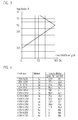
- the amplitude A of these scanning signals S1, S2 is dependent on the position of the scanning unit 2 relative to the scale 1, in particular the scanning distance D. To function in the measuring mode of the position measuring device, it is necessary that the amplitude A does not fall below a certain level. It is therefore particularly important when mounting the scanning unit 2 relative to the scale 1 to adjust the position to the scale 1 such that the amplitude A has a sufficient height at least close to the desired target amplitude (in the example 1V).
- One of the simplest ways is to do it arithmetically S ⁇ 1 2 + S ⁇ 2 2 to build.
- FIG. 2 of the DE 101 57 112 A1 shows an alternative possibility.
- the switching signals are generated by a comparator circuit with two comparators from the sampling signals S1 to S4.
- the multiplexer selects from the sampling signals S1 to S4 in each case the maximum amplitude and sets these selected sampling signals S1 to S4 together to form an envelope which represents the amplitude signal.
- the amplitude signal is directly proportional to the instantaneous amplitude A of the sampling signals S1 to S4.
- the signals for this are in FIG. 3 of the DE 101 57 112 A1 which is incorporated herein by reference.
- the amplitude signal A proportional amplitude signal is also by known rectifier circuits, for example according to the DE 44 28 673 A1 produced.
- the scanning unit 2 has a control device 4 for controlling the amplitude A of the scanning signals S1, S2.
- the control device 4 controls a display unit 5, which signals the operator the current state of the amplitude A.
- the control device 4 comprises a control device 41, which is designed to change the luminous intensity of two light sources 51, 52 of the display unit 5 as a function of the amplitude A of the scanning signals S1, S2.
- the first light source 51 glows green and changes its Luminous intensity as a function of the amplitude, as in FIG. 3 shown.
- the target amplitude is assumed to be 1V.
- the luminosity of the first light source 51, that is, the green light source 51 is in FIG. 4 given as a function of the amplitude A in%.
- the control device 41 additionally controls the second light source 52, which lights up red and also changes its luminous intensity as a function of the amplitude A of the scanning signals S1, S2.
- FIG. 4 the dependence of the luminous intensity of this red-emitting light source 52 is shown.
- the luminosity of the red light source 52 changes in opposite directions to the luminous intensity of the green light source 51, which is symbolically symbolized by an inverter 6. If the amplitude A of the scanning signals S1, S2 is less than 0.3 V, only the red light source 52 with maximum luminous intensity, ie 100%, illuminates. If the amplitude A changes in the direction of the nominal amplitude of 1 V, the luminosity of the red light source 52 decreases continuously, to 0%.
- the luminosity of the green light source 51 changes inversely thereto, so it continuously increases until it reaches the target amplitude of 1 V until it reaches 100%.
- a continuous color mixture is generated, from which the operator receives a useful indication of the current state of the instantaneous amplitude A.
- a further control device 42 is provided according to the invention.
- This control device 42 is designed to control the two light sources 51, 52 of the display unit 5 at least at amplitudes A which are in the range of the target amplitude (60% to 100% of the target amplitude) in such a way as to illuminate the light sources 51, 52 as a function of To interrupt amplitude A, where the number of successive interruptions at equal intervals t is a measure of the amplitude A of the scanning signals S1, S2.
- FIG. 4 the number of interruptions depending on the amplitude is called blinking.
- the Figures 5a, 5b and 5c show in a time chart how the two light sources 51, 52 are driven.
- the number of consecutive breaks at equal intervals t is a measure of the instantaneous amplitude. If the amplitude A is in a range of 0.95 to 1.05 V, the light sources 51, 52 are interrupted once within a cycle T, as in FIG FIG. 5a is shown. If the amplitude A is in a range of 0.85 to 0.95 V, the two light sources 51, 52 are interrupted twice, as in FIG FIG. 5b is shown.
- the two light sources 51, 52 are interrupted three times, as in FIG FIG. 5c is shown.
- the time of an interruption (in the example 50ms) is much smaller than the following time t of illumination until the next interruption (in the example 255ms)
- the cycle of interruptions is repeated in a fixed time frame T, here in the example 2.6s.
- the illustrated embodiment is particularly advantageous by the two light sources 51, 52 in the same way from the control device 42nd be interrupted controlled.
- the amplitudes A in the vicinity of the target amplitude - here 1 V - is particularly of interest, ie in the range of about 60% to 100% of the target amplitude, alternatively, only the green light source 51 could be controlled by the controller 42 and whose lights are interrupted depending on the amplitude A.
- a light source is controlled only by the control device 41 and a further light source only by the control device 42.
- the light sources 51, 52 are preferably light-emitting diodes, which can be mounted on the scanning unit 2 in a space-saving manner and nevertheless visible to the operator.
- the two light emitting diodes 51, 52 are housed in a common housing.
- Such an LED is also called duo LED.
- a differently colored light-emitting diode, in particular a blue one can also be integrated in this housing.
- Such a tricolor LED is also called RGB LED.
- the invention can be used in length and angle measuring devices.
- the scanning elements for generating the scanning signals can be photoelectric elements, magnetic field sensitive, capacitive and inductive elements.
Abstract
Description
- Die Erfindung betrifft eine Abtasteinheit einer Positionsmesseinrichtung. Die Abtasteinheit umfasst eine Kontrollvorrichtung zur Kontrolle der Amplitude zumindest eines analogen Abtastsignals der Abtasteinheit und eine Anzeigeeinheit zur Signalisierung der Amplitudenhöhe.
- Die Kontrolle der Abtastsignale ist insbesondere bei der Montage der Positionsmesseinrichtung erforderlich. Die Signalqualität und somit die Messgenauigkeit ist erheblich von der exakten Justierung der Abtasteinheit relativ zum Maßstab abhängig. Um bei inkrementalen Positionsmesseinrichtungen eine hohe Messgenauigkeit zu gewährleisten, sollen die von der Abtasteinheit erzeugten Abtastsignale eine hohe und gleiche Amplitude sowie einen gegenseitigen Phasenversatz von 90° aufweisen. Die Amplitude wird im Wesentlichen durch die Lage der Abtasteinheit zum Maßstab bestimmt, das heißt Abstand, Verdrehung und seitliche Verschiebung der Abtasteinheit senkrecht zur Messrichtung relativ zum Maßstab.
- Gemäß der
EP 0 514 081 B1 werden die Abtastsignale einer Kontrollvorrichtung zugeführt, welche die Amplitude mit einem Grenzwert vergleicht. Liegt die Amplitude unterhalb dieses Grenzwertes, wird eine Anzeige aktiviert, die als Hinweis dafür dient, dass die Abtasteinheit gegenüber dem Maßstab falsch angebaut ist. - Nachteilig dabei ist, dass die Anzeigeeinheit ausschließlich signalisiert, ob der Abtastkopf korrekt oder nicht korrekt angebaut ist, indem eine grüne oder eine rote Lichtquelle leuchtet.
- Es wurde bereits erkannt, dass dieser Hinweis allein für den Anbau nicht ausreicht und es für den Anwender vorteilhaft wäre, auch einen Hinweis bezüglich der tatsächlichen Höhe der Amplitude zu erhalten. Hierzu wird nun in der
DE 101 57 112 A1 vorgeschlagen, die Amplitude des Abtastsignals mit einem vorgegebenen Sollwert zu vergleichen und in Abhängigkeit der Abweichung die Leuchtstärke einer Lichtquelle als Anzeigeeinheit zu variieren. - Nachteilig dabei ist, dass die Zuordnung von Leuchtstärke zu Amplitudenhöhe für den Anwender schwierig ist.
- Der Erfindung liegt daher die Aufgabe zugrunde, eine Abtasteinheit anzugeben, durch die ein Hinweis erzeugbar ist, der eine bessere Aussage über den Zustand der Amplitude zumindest eines positionsabhängigen Abtastsignals zulässt.
- Diese Aufgabe wird durch eine Abtasteinheit mit den Merkmalen des Anspruches 1 gelöst.
- Demnach weist die Abtasteinheit der Positionsmesseinrichtung eine Kontrollvorrichtung zur Kontrolle der Amplitude eines positionsabhängigen analogen Abtastsignals der Abtasteinheit und eine Anzeigeeinheit zur Signalisierung der Amplitude auf. Die Kontrollvorrichtung ist dazu ausgelegt, zumindest eine Lichtquelle der Anzeigeeinheit derart anzusteuern, um einen Wechsel des Leuchtzustandes der Lichtquelle zu bewirken, welche die Information über die momentane Amplitudenhöhe beinhaltet. Besonders vorteilhaft ist, wenn die Anzahl der aufeinanderfolgenden Wechsel ein Maß für die Amplitude des Abtastsignals ist.
- Ein Maß für die Amplitude bedeutet dabei entweder direkt proportional zur Größe der momentanen Amplitude oder die Abweichung zwischen der momentanen Amplitude und der gewünschten Sollamplitude.
- Bevorzugt ist die Kontrollvorrichtung dazu ausgelegt, die Lichtquelle in einem Bereich von 60% bis 100% der Sollamplitude in zumindest vier voneinander unterscheidbare Zustände zu versetzten, wobei diese Zustände sich in der Anzahl der Wechsel des Leuchtzustandes unterscheiden. Durch diese Maßnahme erhält der Bediener eine aussagefähige Information über die Tendenz der Amplitude, wobei sich die Anzahl der Wechsel des Leuchtzustandes über den Bereich 60% bis 100% der Sollamplitude für den Bediener sichtbar fast kontinuierlich ändert. Der somit generierte und sichtbare Hinweis ist eine Art digitale Anzeige, die das Maß der Amplitude darstellt.
- Der Wechsel des Leuchtzustandes kann eine Änderung der Blinkfrequenz sein, eine Art Morsecode oder in besonders bevorzugter Weise eine Unterbrechung des Leuchtens der Lichtquelle der Anzeigeeinheit, wobei die Anzahl der jeweils in gleichen Zeitabständen aufeinanderfolgenden Unterbrechungen ein Maß für die Amplitude des Abtastsignals ist. Bei dem besonders bevorzugten Ausführungsbeispiel sind die Zeitabstände der aufeinanderfolgenden Unterbrechungen, also die Frequenz, bei allen Amplituden gleich, so dass der Bediener bei allen Amplituden nur die Anzahl der aufeinanderfolgenden Unterbrechungen zählen muss und diese Anzahl eindeutig als Maß der Amplitude interpretieren kann. Eine Unterbrechung des Leuchtens der Lichtquelle entspricht einem Ausschalten der Lichtquelle.
- In einer Ausgestaltung der Erfindung weist die Kontrollvorrichtung eine erste Steuereinrichtung auf, die dazu ausgelegt ist, die Lichtquelle der Anzeigeeinheit derart anzusteuern, um das Leuchten der Lichtquelle in Abhängigkeit der Amplitude zu unterbrechen, wobei die Anzahl der jeweils in gleichen Zeitabständen aufeinanderfolgenden Unterbrechungen ein Maß für die Amplitude des Abtastsignals ist. Zusätzlich weist die Kontrollvorrichtung eine zweite Steuereinrichtung auf, welche dazu ausgelegt ist, die Leuchtstärke dieser Lichtquelle oder einer anderen Lichtquelle der Anzeigeeinheit proportional zur Amplitude des Abtastsignals zu verändern. Vorzugsweise steuern beide Steuereinrichtungen eine gemeinsame Lichtquelle an, wobei einerseits die Leuchtstärke dieser Lichtquelle bei Erhöhung der Amplitude in Richtung der Sollamplitude ansteigt und gleichzeitig das Leuchten in vorgegebenen Zeitabständen kurz unterbrochen wird. Diese Unterbrechungen sind derart, dass sie vom Bediener gezählt werden können und die Zahl aufeinanderfolgender Unterbrechungen ein Maß für die Amplitude des Abtastsignals darstellt. Die Zeitdauer des Leuchtens zwischen zwei aufeinanderfolgenden Unterbrechungen ist größer als die Zeitdauer einer Unterbrechung selbst. Somit bleibt für den Bediener auch die Information der Leuchtstärke als Qualitätskriterium der Amplitude gut sichtbar.
- In einer weiteren bevorzugten Ausgestaltung umfasst die Anzeigeeinheit zwei Lichtquellen, wobei jeweils beide Lichtquellen von der ersten Steuereinrichtung sowie von der zweiten Steuereinrichtung angesteuert sind, und die zweite Steuereinrichtung die Leuchtstärke beider Lichtquellen invers zueinander verändert. Dabei ist eine der beiden Lichtquellen grün leuchtend und die andere der beiden Lichtquellen rot leuchtend. Die Leuchtstärke der grün leuchtenden Lichtquelle wird bei steigender Amplitude in Richtung der Sollamplitude erhöht, wogegen die Leuchtstärke der rot leuchtenden Lichtquelle bei steigender Amplitude in Richtung der Sollamplitude verringert wird.
- Eine Positionsmesseinrichtung mit einer erfindungsgemäß ausgestalteten Abtasteinheit ist im Anspruch 8 angegeben.
- Einzelheiten sowie Vorteile der Erfindung ergeben sich aus der nachfolgenden Beschreibung eines Ausführungsbeispiels der Erfindung anhand der Figuren. Dabei zeigt:
- Figur 1
- eine Positionsmesseinrichtung mit einer Abtasteinheit und einer Anzeigeeinheit;
- Figur 2
- eine Kontrolleinheit und die Anzeigeeinheit der Abtasteinheit;
- Figur 3
- den Verlauf eines von der Amplitude abhängigen Ansteuersignals der Anzeigeeinheit;
- Figur 4
- eine tabellarische Darstellung der Ansteuerung der Anzeigeeinheit in Abhängigkeit von der Amplitude, und
- Figur 5a, 5b, 5c
- die zeitliche Ansteuerung der Anzeigeeinheit.
- Die in
Figur 1 dargestellte Positionsmesseinrichtung besteht aus einem Maßstab 1 sowie einer Abtasteinheit 2. Der Maßstab 1 ist beispielsweise ein Maßband, das an seiner Oberfläche eine Teilung 3, bestehend aus abwechselnd reflektierenden Bereichen und nicht reflektierenden Bereichen aufweist. Die Abtasteinheit 2 tastet die Teilung 3 des Maßstabes 1 in Messrichtung X ab und erzeugt dabei mehrere um 90° gegeneinander phasenverschobene periodische analoge Abtastsignale S1, S2, auch Quadratursignale genannt, wobei S1 = A×sin a einer Sinusfunktion und S2 = A×cos a einer Cosinusfunktion folgt. Die Amplitude A dieser Abtastsignale S1, S2 ist abhängig von der Lage der Abtasteinheit 2 relativ zum Maßstab 1, insbesondere vom Abtastabstand D. Zur Funktionsfähigkeit im Messbetrieb der Positionsmesseinrichtung ist es erforderlich, dass die Amplitude A ein bestimmtes Maß nicht unterschreitet. Es ist deshalb bei der Montage der Abtasteinheit 2 relativ zum Maßstab 1 besonders wichtig, die Lage zum Maßstab 1 derart einzustellen, dass die Amplitude A eine ausreichende Höhe zumindest nahe der gewünschten Sollamplitude (im Beispiel 1V) aufweist. - Es gibt nun mehrere an sich bekannte Möglichkeiten, aus mehreren um 90° gegeneinander phasenverschobenen Abtastsignalen S1, S2 ein amplitudenproportionales Signal, welches die Amplitude A repräsentiert, zu erzeugen.
- Eine der einfachsten Möglichkeiten besteht darin, es rechnerisch durch

- Die
Figur 2 derDE 101 57 112 A1 zeigt eine alternative Möglichkeit auf. Verwendet wird ein Multiplexer, dem einerseits vier jeweils um 90° gegeneinander phasenverschobene Abtastsignale S1 = A×sin a, S2 = A×cos a, S3 = -A×sin a, S4 = -A×cos a zugeführt werden und dem andererseits über Steuereingänge Umschaltsignale zugeführt werden. Die Umschaltsignale werden von einer Komparatorschaltung mit zwei Komparatoren aus den Abtastsignalen S1 bis S4 erzeugt. Der Multiplexer selektiert dabei aus den Abtastsignalen S1 bis S4 jeweils das mit maximaler Amplitude und setzt diese selektierten Abtastsignale S1 bis S4 zu einer Hüllkurve zusammen, welches das Amplitudensignal darstellt. Das Amplitudensignal ist direkt proportional zur momentanen Amplitude A der Abtastsignale S1 bis S4. Die Signale hierzu sind inFigur 3 derDE 101 57 112 A1 dargestellt, auf die hier ausdrücklich Bezug genommen wird. - Das der Amplitude A proportionale Amplitudensignal ist auch durch bekannte Gleichrichterschaltungen, beispielsweise gemäß der
DE 44 28 673 A1 erzeugbar. - Die Abtasteinheit 2 weist eine Kontrollvorrichtung 4 zur Kontrolle der Amplitude A der Abtastsignale S1, S2 auf. Die Kontrollvorrichtung 4 steuert eine Anzeigeeinheit 5 an, welche dem Bediener den momentanen Zustand der Amplitude A signalisiert.
- Hierzu umfasst die Kontrollvorrichtung 4 eine Steuereinrichtung 41, welche dazu ausgelegt ist, die Leuchtstärke zweier Lichtquellen 51, 52 der Anzeigeeinheit 5 in Abhängigkeit der Amplitude A der Abtastsignale S1, S2 zu verändern. Die erste Lichtquelle 51 leuchtet grün und ändert ihre Leuchtstärke in Abhängigkeit der Amplitude, wie in
Figur 3 dargestellt. In diesem Beispiel ist die Sollamplitude mit 1 V angenommen. Die Leuchtstärke der ersten Lichtquelle 51, also der grün leuchtenden Lichtquelle 51, ist inFigur 4 in Abhängigkeit der Amplitude A in % angegeben. - Die Steuereinrichtung 41 steuert zusätzlich die zweite Lichtquelle 52 an, die rot leuchtet und ihre Leuchtstärke ebenfalls in Abhängigkeit der Amplitude A der Abtastsignale S1, S2 verändert. In
Figur 4 ist die Abhängigkeit der Leuchtstärke dieser rot leuchtenden Lichtquelle 52 dargestellt. Die Leuchtstärke der roten Lichtquelle 52 verändert sich gegensinnig zur Leuchtstärke der grünen Lichtquelle 51, was schaltungstechnisch durch einen Inverter 6 symbolisiert ist. Liegt die Amplitude A der Abtastsignale S1, S2 unter 0,3 V, leuchtet ausschließlich die rote Lichtquelle 52 mit maximaler Leuchtstärke, also 100%. Verändert sich die Amplitude A in Richtung der Sollamplitude von 1 V, verringert sich die Leuchtstärke der roten Lichtquelle 52 kontinuierlich, bis 0%. Die Leuchtstärke der grünen Lichtquelle 51 verändert sich invers dazu, nimmt also kontinuierlich bis zum Erreichen der Sollamplitude von 1 V stetig zu, bis sie 100% erreicht. Durch diese gegenläufige Veränderung der Leuchtstärke beider Lichtquellen 51, 52 wird eine kontinuierliche Farbmischung generiert, aus welcher der Bediener einen brauchbaren Hinweis über den aktuellen Zustand der momentanen Amplitude A erhält. - Bei der Montage der Abtasteinheit 2 ist es besonders wichtig, dass die Lage der Abtasteinheit 2 gegenüber dem Maßstab 1 derart eingestellt wird, dass die Amplitude zumindest nahe der Sollamplitude von 1 V zu liegen kommt. Um nun insbesondere in einem Bereich von etwa 60% bis 100% dem Bediener noch mehr Informationen zur aktuellen Amplitude A und somit den aktuellen Anbauzustand an die Hand zu geben, ist erfindungsgemäß eine weitere Steuereinrichtung 42 vorgesehen. Diese Steuereinrichtung 42 ist dazu ausgelegt, die beiden Lichtquellen 51, 52 der Anzeigeeinheit 5 zumindest bei Amplituden A, die im Bereich der Sollamplitude liegen (60% bis 100% der Sollamplitude) derart anzusteuern, um das Leuchten der Lichtquellen 51, 52 in Abhängigkeit der Amplitude A zu unterbrechen, wobei die Anzahl der jeweils in gleichen Zeitabständen t aufeinanderfolgenden Unterbrechungen ein Maß für die Amplitude A der Abtastsignale S1, S2 ist.
- In
Figur 4 ist die Anzahl der Unterbrechungen in Abhängigkeit der Amplitude als Blinken bezeichnet. DieFiguren 5a, 5b und 5c zeigen in einem Zeitdiagramm, wie die beiden Lichtquellen 51, 52 angesteuert werden. Die Anzahl der in gleichen Abständen t aufeinanderfolgenden Unterbrechungen ist ein Maß für die momentane Amplitude. Liegt die Amplitude A in einem Bereich von 0,95 bis 1,05 V, werden die Lichtquellen 51, 52 innerhalb eines Zyklusses T einmal unterbrochen, wie inFigur 5a dargestellt ist. Liegt die Amplitude A in einem Bereich von 0,85 bis 0,95 V, werden die beiden Lichtquellen 51, 52 zweimal unterbrochen, wie inFigur 5b dargestellt ist. Liegt die Amplitude A in einem Bereich von 0,75 bis 0,85 V, werden die beiden Lichtquellen 51, 52 dreimal unterbrochen, wie inFigur 5c dargestellt ist. Die Unterbrechungen erfolgen bei allen Amplituden A in aufeinanderfolgend gleichen Abständen t, im Beispiel ist t=255ms, wobei die Zeit jeweils einer Unterbrechung 50ms beträgt. Die Zeit einer Unterbrechung (im Beispiel 50ms) ist viel kleiner als die darauf folgende Zeit t des Leuchtens bis zur nächsten Unterbrechung (im Beispiel 255ms) Der Zyklus der Unterbrechungen wiederholt sich in einem festen Zeitraster T, hier im Beispiel 2,6s. Besonders anzumerken ist, dass nicht die Frequenz der Unterbrechungen als Maß für die Amplitude A verwendet wird, sondern nur die Anzahl der Unterbrechungen, wobei die Frequenz der aufeinanderfolgenden Unterbrechungen innerhalb eines Zyklusses T bei allen Amplituden A gleich ist. Der Bediener erhält somit eine verbesserte Information über den tatsächlichen Zustand der Amplitude A durch einfaches Abzählen der innerhalb eines Zyklusses auftretenden aufeinanderfolgenden Unterbrechungen der Lichtquellen 51, 52. Die Anzahl der Unterbrechungen, also der aufeinanderfolgenden Ausschaltzustände der Lichtquelle 51, 52 ändert sich zumindest im Bereich 60% bis 100% der Sollamplitude kontinuierlich. - Das dargestellte Ausführungsbeispiel ist besonders vorteilhaft, indem die beiden Lichtquellen 51, 52 in gleicher Weise von der Steuereinrichtung 42 angesteuert unterbrochen werden. Da für den Bediener die Amplituden A in der Nähe der Sollamplitude - hier 1 V - besonders von Interesse ist, also im Bereich von etwa 60% bis 100% der Sollamplitude, könnte alternativ nur die grün leuchtende Lichtquelle 51 von der Steuereinrichtung 42 angesteuert werden und deren Leuchten abhängig von der Amplitude A unterbrochen werden. Eine weitere Alternative wäre, dass eine Lichtquelle nur von der Steuereinrichtung 41 und eine weitere Lichtquelle nur von der Steuereinrichtung 42 angesteuert wird.
- Die Lichtquellen 51, 52 sind vorzugsweise Leuchtdioden, die platzsparend und trotzdem für den Bediener gut sichtbar an der Abtasteinheit 2 angebracht werden können. Bevorzugt sind die beiden Leuchtdioden 51, 52 in einem gemeinsamen Gehäuse untergebracht. Eine derartige LED wird auch Duo-LED bezeichnet. Soll zusätzlich die Lage einer auf dem Maßstab 1 angeordneten Referenzmarke überprüft werden, kann in diesem Gehäuse auch noch eine andersfarbige Leuchtdiode, insbesondere eine blaue, integriert sein. Eine derartige dreifarbige Leuchtdiode wird auch RGB-LED genannt.
- Die Erfindung ist bei Längen- sowie Winkelmesseinrichtungen einsetzbar. Die Abtastelemente zur Erzeugung der Abtastsignale können dabei lichtelektrische Elemente, magnetfeldempfindliche, kapazitive sowie induktive Elemente sein.
Claims (8)
- Abtasteinheit einer Positionsmesseinrichtung zur Abtastung eines Maßstabs (1),
mit einer Kontrollvorrichtung (4) zur Kontrolle der Amplitude (A) zumindest eines analogen Abtastsignals (S1, S2) der Abtasteinheit (2) und mit einer Anzeigeeinheit (5) zur Signalisierung der Amplitude (A), dadurch gekennzeichnet, dass
die Kontrollvorrichtung (4) dazu ausgelegt ist, zumindest eine Lichtquelle (51, 52) der Anzeigeeinheit (5) derart anzusteuern, um einen Wechsel des Leuchtzustandes der Lichtquelle (51, 52) zu bewirken, wobei die aufeinanderfolgenden Wechsel die Information über die Amplitude (A) des Abtastsignals (S1, S2) beinhalten. - Abtasteinheit nach Anspruch 1, dadurch gekennzeichnet, dass die Anzahl der aufeinanderfolgenden Wechsel ein Maß für die Amplitude (A) des Abtastsignals (S1, S2) ist
- Abtasteinheit nach Anspruch 2, dadurch gekennzeichnet, dass die Kontrollvorrichtung (4) dazu ausgelegt ist, die Lichtquelle (51, 52) in einem Bereich von 60% bis 100% der Sollamplitude in zumindest vier voneinander unterscheidbare Zustände zu versetzten, wobei diese Zustände sich in der Anzahl der Wechsel des Leuchtzustandes unterscheiden.
- Abtasteinheit nach einem der vorhergehenden Ansprüche 2 oder 3, dadurch gekennzeichnet, dass der Wechsel des Leuchtzustandes eine Unterbrechung des Leuchtens der Lichtquelle (51, 52) der Anzeigeeinheit (5) ist, wobei die Anzahl der jeweils in gleichen Zeitabständen (t) aufeinanderfolgenden Unterbrechungen ein Maß für die Amplitude (A) des Abtastsignals (S1, S2) ist.
- Abtasteinheit nach einem der vorhergehenden Ansprüche 2 bis 4, dadurch gekennzeichnet, dass die Kontrollvorrichtung (4) eine erste Steuereinrichtung (42) aufweist, die dazu ausgelegt ist, die Lichtquelle (51, 52) der Anzeigeeinheit (5) derart anzusteuern, um das Leuchten der Lichtquelle (51, 52) in Abhängigkeit der Amplitude (A) zu unterbrechen, wobei die Anzahl der jeweils in gleichen Zeitabständen (t) aufeinanderfolgenden Unterbrechungen ein Maß für die Amplitude (A) des Abtastsignals (S1, S2) ist, und dass die Kontrollvorrichtung (4) eine zweite Steuereinrichtung (41) aufweist, welche dazu ausgelegt ist die Leuchtstärke dieser Lichtquelle (51, 52) oder einer anderen Lichtquelle der Anzeigeeinheit (5) in Abhängigkeit der Amplitude (A) des Abtastsignals (S1, S2) zu verändern.
- Abtasteinheit nach Anspruch 5, dadurch gekennzeichnet, dass die Anzeigeeinheit (5) zwei Lichtquellen (51, 52) umfasst, wobei jeweils beide Lichtquellen (51, 52) von der ersten Steuereinrichtung (41) sowie von der zweiten Steuereinrichtung (42) angesteuert sind, und die zweite Steuereinrichtung (41) die Leuchtstärke beider Lichtquellen (51, 52) invers zueinander verändert.
- Abtasteinheit nach Anspruch 6, dadurch gekennzeichnet, dass eine der Lichtquellen (51) grün leuchtend und die andere der Lichtquellen (52) rot leuchtend ist.
- Positionsmesseinrichtung mit einem Maßstab (1) und einer diesen abtastenden Abtasteinheit (2) gemäß einem der vorhergehenden Ansprüche.
Applications Claiming Priority (1)
| Application Number | Priority Date | Filing Date | Title |
|---|---|---|---|
| DE102009046773A DE102009046773A1 (de) | 2009-11-17 | 2009-11-17 | Abtasteinheit einer Positionsmesseinrichtung |
Publications (3)
| Publication Number | Publication Date |
|---|---|
| EP2325609A2 true EP2325609A2 (de) | 2011-05-25 |
| EP2325609A3 EP2325609A3 (de) | 2014-02-26 |
| EP2325609B1 EP2325609B1 (de) | 2015-10-14 |
Family
ID=43467003
Family Applications (1)
| Application Number | Title | Priority Date | Filing Date |
|---|---|---|---|
| EP10170753.7A Active EP2325609B1 (de) | 2009-11-17 | 2010-07-26 | Abtasteinheit einer Positionsmesseinrichtung |
Country Status (5)
| Country | Link |
|---|---|
| US (1) | US8633428B2 (de) |
| EP (1) | EP2325609B1 (de) |
| KR (1) | KR101742319B1 (de) |
| DE (1) | DE102009046773A1 (de) |
| ES (1) | ES2550977T3 (de) |
Families Citing this family (3)
| Publication number | Priority date | Publication date | Assignee | Title |
|---|---|---|---|---|
| DE102014209004A1 (de) * | 2014-05-13 | 2015-11-19 | Dr. Johannes Heidenhain Gmbh | Positionsmesseinrichtung |
| DE102017208317A1 (de) * | 2017-05-17 | 2018-11-22 | Festo Ag & Co. Kg | Sensoreinrichtung und System |
| CN111678544B (zh) * | 2020-06-05 | 2023-09-15 | 南京俏声波动科技有限公司 | 一种平衡双向输出高压波源装置及其工作方法 |
Citations (3)
| Publication number | Priority date | Publication date | Assignee | Title |
|---|---|---|---|---|
| DE4428673A1 (de) | 1994-08-12 | 1996-02-15 | Siemens Ag | Vorrichtung zur Bildung einer Steuergröße, welche ein Maß für die Amplitude zweier frequenz- und amplitudengleichen, phasenstarren sinus- und cosinusförmigen Meßwechselgrößen ist |
| EP0514081B1 (de) | 1991-05-16 | 1996-02-28 | Renishaw Transducer Systems Limited | Justierung von Quadratursignalen |
| DE10157112A1 (de) | 2001-11-21 | 2003-06-05 | Heidenhain Gmbh Dr Johannes | Kontrollvorrichtung einer Positionsmesseinrichtung |
Family Cites Families (7)
| Publication number | Priority date | Publication date | Assignee | Title |
|---|---|---|---|---|
| SU930608A1 (ru) * | 1980-07-22 | 1982-05-23 | Войсковая часть 70170 | Генератор пачек импульсов |
| DE4413697A1 (de) * | 1994-04-20 | 1995-10-26 | Pfisterer Elektrotech Karl | Vorrichtung zur Anzeige der Spannung eines Leiters eines Hochspannungsenergieversorgungssystems |
| DE29712803U1 (de) * | 1997-07-19 | 1997-09-18 | Goetz Karina | Warneinrichtung mit Sensoren |
| DE10244234A1 (de) * | 2002-09-23 | 2004-03-25 | Dr. Johannes Heidenhain Gmbh | Positionsmesseinrichtung |
| JP2005128002A (ja) * | 2003-10-01 | 2005-05-19 | Olympus Corp | エンコーダ |
| US7045769B2 (en) * | 2003-10-29 | 2006-05-16 | The Boeing Company | Optical encoders for position measurements |
| DE102005006247A1 (de) * | 2005-02-11 | 2006-08-17 | Dr. Johannes Heidenhain Gmbh | Positionsmesseinrichtung |
-
2009
- 2009-11-17 DE DE102009046773A patent/DE102009046773A1/de not_active Withdrawn
-
2010
- 2010-07-26 ES ES10170753.7T patent/ES2550977T3/es active Active
- 2010-07-26 EP EP10170753.7A patent/EP2325609B1/de active Active
- 2010-09-10 KR KR1020100088933A patent/KR101742319B1/ko active IP Right Grant
- 2010-11-15 US US12/927,439 patent/US8633428B2/en active Active
Patent Citations (3)
| Publication number | Priority date | Publication date | Assignee | Title |
|---|---|---|---|---|
| EP0514081B1 (de) | 1991-05-16 | 1996-02-28 | Renishaw Transducer Systems Limited | Justierung von Quadratursignalen |
| DE4428673A1 (de) | 1994-08-12 | 1996-02-15 | Siemens Ag | Vorrichtung zur Bildung einer Steuergröße, welche ein Maß für die Amplitude zweier frequenz- und amplitudengleichen, phasenstarren sinus- und cosinusförmigen Meßwechselgrößen ist |
| DE10157112A1 (de) | 2001-11-21 | 2003-06-05 | Heidenhain Gmbh Dr Johannes | Kontrollvorrichtung einer Positionsmesseinrichtung |
Also Published As
| Publication number | Publication date |
|---|---|
| US8633428B2 (en) | 2014-01-21 |
| ES2550977T3 (es) | 2015-11-13 |
| DE102009046773A1 (de) | 2011-05-19 |
| US20110116102A1 (en) | 2011-05-19 |
| KR20110055372A (ko) | 2011-05-25 |
| EP2325609B1 (de) | 2015-10-14 |
| EP2325609A3 (de) | 2014-02-26 |
| KR101742319B1 (ko) | 2017-06-15 |
Similar Documents
| Publication | Publication Date | Title |
|---|---|---|
| EP0058302B1 (de) | Lichtelektrische inkrementale Positioniereinrichtung | |
| DE3144334C2 (de) | Wegmeßeinrichtung mit Referenzmarken | |
| DE2952106A1 (de) | Lichtelektrische inkrementale positioniereinrichtung | |
| EP1754069A1 (de) | Stromsensor | |
| DE19707263B4 (de) | Verfahren zum Einstellen von Schaltpunkten bei einem Sensor-Ausgangssignal | |
| EP2325609B1 (de) | Abtasteinheit einer Positionsmesseinrichtung | |
| EP0836077B1 (de) | Kontrollvorrichtung und Verfahren zur Prüfung von positionsabhängigen Abtastsignalen | |
| EP0036976A1 (de) | Prüfeinrichtung für ein digitales elektrisches Längen- oder Winkelmessystem | |
| EP2210018B1 (de) | Sensor für die schaltstellung einer schaltwelle und entsprechendes ermittlungsverfahren | |
| AT393029B (de) | Inkrementales laengenmesssystem | |
| WO2003004298A1 (de) | Anzeigeinstrument | |
| EP2334218B1 (de) | Küchengerät mit motordrehzahlanzeige | |
| DE3127220C2 (de) | Vorrichtung zum Erzeugen einer drehzahlabhängigen Signalfolge | |
| EP1314965B1 (de) | Kontrollvorrichtung einer Positionsmesseinrichtung | |
| DE102007044679B3 (de) | Konfigurationsmittel für Sicherheits-Lichtgitter | |
| DE69726347T2 (de) | Verfahren und Gerät zur Ausführung von mehreren Dimmstrategien | |
| DE112014005342B4 (de) | Verfahren zum Auffinden eines Startpunkts für eine Abstandsmessung unter Verwendung einer Abstandsmesseinrichtung | |
| DE102016208649A1 (de) | Vorrichtung und Verfahren zum Erfassen einer Lageänderung eines Signalgeberrads | |
| EP2564242A1 (de) | Gabellichtschranke, vorrichtung und verfahren zur positionsbestimmung mittels einer gabellichtschranke | |
| EP1192369A1 (de) | Vorrichtung zum erfassen einer stellung eines stellelements | |
| AT396840B (de) | Vorrichtung zur erzeugung von referenzsignalen | |
| EP0855800A1 (de) | Induktive Endstellungsabfrageeinrichtung | |
| DE60222010T2 (de) | Rotationsdetektor | |
| DE1938377C (de) | Digitale Absolut Meßanordnung mit Syn chronisation des Ziffernsprungs in den Grob stellen der Anzeige | |
| DE102006015883B4 (de) | Schieberegler |
Legal Events
| Date | Code | Title | Description |
|---|---|---|---|
| PUAI | Public reference made under article 153(3) epc to a published international application that has entered the european phase |
Free format text: ORIGINAL CODE: 0009012 |
|
| AK | Designated contracting states |
Kind code of ref document: A2 Designated state(s): AL AT BE BG CH CY CZ DE DK EE ES FI FR GB GR HR HU IE IS IT LI LT LU LV MC MK MT NL NO PL PT RO SE SI SK SM TR |
|
| AX | Request for extension of the european patent |
Extension state: BA ME RS |
|
| PUAL | Search report despatched |
Free format text: ORIGINAL CODE: 0009013 |
|
| AK | Designated contracting states |
Kind code of ref document: A3 Designated state(s): AL AT BE BG CH CY CZ DE DK EE ES FI FR GB GR HR HU IE IS IT LI LT LU LV MC MK MT NL NO PL PT RO SE SI SK SM TR |
|
| AX | Request for extension of the european patent |
Extension state: BA ME RS |
|
| RIC1 | Information provided on ipc code assigned before grant |
Ipc: G01D 5/244 20060101AFI20140121BHEP |
|
| 17P | Request for examination filed |
Effective date: 20140826 |
|
| RBV | Designated contracting states (corrected) |
Designated state(s): AL AT BE BG CH CY CZ DE DK EE ES FI FR GB GR HR HU IE IS IT LI LT LU LV MC MK MT NL NO PL PT RO SE SI SK SM TR |
|
| GRAP | Despatch of communication of intention to grant a patent |
Free format text: ORIGINAL CODE: EPIDOSNIGR1 |
|
| INTG | Intention to grant announced |
Effective date: 20150716 |
|
| GRAS | Grant fee paid |
Free format text: ORIGINAL CODE: EPIDOSNIGR3 |
|
| GRAA | (expected) grant |
Free format text: ORIGINAL CODE: 0009210 |
|
| AK | Designated contracting states |
Kind code of ref document: B1 Designated state(s): AL AT BE BG CH CY CZ DE DK EE ES FI FR GB GR HR HU IE IS IT LI LT LU LV MC MK MT NL NO PL PT RO SE SI SK SM TR |
|
| REG | Reference to a national code |
Ref country code: GB Ref legal event code: FG4D Free format text: NOT ENGLISH |
|
| REG | Reference to a national code |
Ref country code: AT Ref legal event code: REF Ref document number: 755486 Country of ref document: AT Kind code of ref document: T Effective date: 20151015 Ref country code: CH Ref legal event code: EP |
|
| REG | Reference to a national code |
Ref country code: CH Ref legal event code: NV Representative=s name: ICB INGENIEURS CONSEILS EN BREVETS SA, CH |
|
| REG | Reference to a national code |
Ref country code: IE Ref legal event code: FG4D Free format text: LANGUAGE OF EP DOCUMENT: GERMAN |
|
| REG | Reference to a national code |
Ref country code: ES Ref legal event code: FG2A Ref document number: 2550977 Country of ref document: ES Kind code of ref document: T3 Effective date: 20151113 |
|
| REG | Reference to a national code |
Ref country code: DE Ref legal event code: R096 Ref document number: 502010010451 Country of ref document: DE |
|
| REG | Reference to a national code |
Ref country code: NL Ref legal event code: MP Effective date: 20151014 |
|
| REG | Reference to a national code |
Ref country code: LT Ref legal event code: MG4D |
|
| PG25 | Lapsed in a contracting state [announced via postgrant information from national office to epo] |
Ref country code: NO Free format text: LAPSE BECAUSE OF FAILURE TO SUBMIT A TRANSLATION OF THE DESCRIPTION OR TO PAY THE FEE WITHIN THE PRESCRIBED TIME-LIMIT Effective date: 20160114 Ref country code: LT Free format text: LAPSE BECAUSE OF FAILURE TO SUBMIT A TRANSLATION OF THE DESCRIPTION OR TO PAY THE FEE WITHIN THE PRESCRIBED TIME-LIMIT Effective date: 20151014 Ref country code: IS Free format text: LAPSE BECAUSE OF FAILURE TO SUBMIT A TRANSLATION OF THE DESCRIPTION OR TO PAY THE FEE WITHIN THE PRESCRIBED TIME-LIMIT Effective date: 20160214 Ref country code: NL Free format text: LAPSE BECAUSE OF FAILURE TO SUBMIT A TRANSLATION OF THE DESCRIPTION OR TO PAY THE FEE WITHIN THE PRESCRIBED TIME-LIMIT Effective date: 20151014 Ref country code: HR Free format text: LAPSE BECAUSE OF FAILURE TO SUBMIT A TRANSLATION OF THE DESCRIPTION OR TO PAY THE FEE WITHIN THE PRESCRIBED TIME-LIMIT Effective date: 20151014 |
|
| PG25 | Lapsed in a contracting state [announced via postgrant information from national office to epo] |
Ref country code: PL Free format text: LAPSE BECAUSE OF FAILURE TO SUBMIT A TRANSLATION OF THE DESCRIPTION OR TO PAY THE FEE WITHIN THE PRESCRIBED TIME-LIMIT Effective date: 20151014 Ref country code: SE Free format text: LAPSE BECAUSE OF FAILURE TO SUBMIT A TRANSLATION OF THE DESCRIPTION OR TO PAY THE FEE WITHIN THE PRESCRIBED TIME-LIMIT Effective date: 20151014 Ref country code: PT Free format text: LAPSE BECAUSE OF FAILURE TO SUBMIT A TRANSLATION OF THE DESCRIPTION OR TO PAY THE FEE WITHIN THE PRESCRIBED TIME-LIMIT Effective date: 20160215 Ref country code: LV Free format text: LAPSE BECAUSE OF FAILURE TO SUBMIT A TRANSLATION OF THE DESCRIPTION OR TO PAY THE FEE WITHIN THE PRESCRIBED TIME-LIMIT Effective date: 20151014 Ref country code: GR Free format text: LAPSE BECAUSE OF FAILURE TO SUBMIT A TRANSLATION OF THE DESCRIPTION OR TO PAY THE FEE WITHIN THE PRESCRIBED TIME-LIMIT Effective date: 20160115 Ref country code: FI Free format text: LAPSE BECAUSE OF FAILURE TO SUBMIT A TRANSLATION OF THE DESCRIPTION OR TO PAY THE FEE WITHIN THE PRESCRIBED TIME-LIMIT Effective date: 20151014 |
|
| REG | Reference to a national code |
Ref country code: DE Ref legal event code: R097 Ref document number: 502010010451 Country of ref document: DE |
|
| PG25 | Lapsed in a contracting state [announced via postgrant information from national office to epo] |
Ref country code: CZ Free format text: LAPSE BECAUSE OF FAILURE TO SUBMIT A TRANSLATION OF THE DESCRIPTION OR TO PAY THE FEE WITHIN THE PRESCRIBED TIME-LIMIT Effective date: 20151014 |
|
| PLBE | No opposition filed within time limit |
Free format text: ORIGINAL CODE: 0009261 |
|
| STAA | Information on the status of an ep patent application or granted ep patent |
Free format text: STATUS: NO OPPOSITION FILED WITHIN TIME LIMIT |
|
| PG25 | Lapsed in a contracting state [announced via postgrant information from national office to epo] |
Ref country code: EE Free format text: LAPSE BECAUSE OF FAILURE TO SUBMIT A TRANSLATION OF THE DESCRIPTION OR TO PAY THE FEE WITHIN THE PRESCRIBED TIME-LIMIT Effective date: 20151014 Ref country code: SM Free format text: LAPSE BECAUSE OF FAILURE TO SUBMIT A TRANSLATION OF THE DESCRIPTION OR TO PAY THE FEE WITHIN THE PRESCRIBED TIME-LIMIT Effective date: 20151014 Ref country code: SK Free format text: LAPSE BECAUSE OF FAILURE TO SUBMIT A TRANSLATION OF THE DESCRIPTION OR TO PAY THE FEE WITHIN THE PRESCRIBED TIME-LIMIT Effective date: 20151014 Ref country code: RO Free format text: LAPSE BECAUSE OF FAILURE TO SUBMIT A TRANSLATION OF THE DESCRIPTION OR TO PAY THE FEE WITHIN THE PRESCRIBED TIME-LIMIT Effective date: 20151014 Ref country code: DK Free format text: LAPSE BECAUSE OF FAILURE TO SUBMIT A TRANSLATION OF THE DESCRIPTION OR TO PAY THE FEE WITHIN THE PRESCRIBED TIME-LIMIT Effective date: 20151014 |
|
| 26N | No opposition filed |
Effective date: 20160715 |
|
| PG25 | Lapsed in a contracting state [announced via postgrant information from national office to epo] |
Ref country code: SI Free format text: LAPSE BECAUSE OF FAILURE TO SUBMIT A TRANSLATION OF THE DESCRIPTION OR TO PAY THE FEE WITHIN THE PRESCRIBED TIME-LIMIT Effective date: 20151014 |
|
| PG25 | Lapsed in a contracting state [announced via postgrant information from national office to epo] |
Ref country code: BE Free format text: LAPSE BECAUSE OF NON-PAYMENT OF DUE FEES Effective date: 20160731 |
|
| PG25 | Lapsed in a contracting state [announced via postgrant information from national office to epo] |
Ref country code: MC Free format text: LAPSE BECAUSE OF FAILURE TO SUBMIT A TRANSLATION OF THE DESCRIPTION OR TO PAY THE FEE WITHIN THE PRESCRIBED TIME-LIMIT Effective date: 20151014 |
|
| PG25 | Lapsed in a contracting state [announced via postgrant information from national office to epo] |
Ref country code: FR Free format text: LAPSE BECAUSE OF NON-PAYMENT OF DUE FEES Effective date: 20160801 |
|
| REG | Reference to a national code |
Ref country code: FR Ref legal event code: ST Effective date: 20170331 |
|
| REG | Reference to a national code |
Ref country code: IE Ref legal event code: MM4A |
|
| PG25 | Lapsed in a contracting state [announced via postgrant information from national office to epo] |
Ref country code: IE Free format text: LAPSE BECAUSE OF NON-PAYMENT OF DUE FEES Effective date: 20160726 |
|
| PG25 | Lapsed in a contracting state [announced via postgrant information from national office to epo] |
Ref country code: LU Free format text: LAPSE BECAUSE OF NON-PAYMENT OF DUE FEES Effective date: 20160726 |
|
| REG | Reference to a national code |
Ref country code: AT Ref legal event code: MM01 Ref document number: 755486 Country of ref document: AT Kind code of ref document: T Effective date: 20160726 |
|
| PG25 | Lapsed in a contracting state [announced via postgrant information from national office to epo] |
Ref country code: AT Free format text: LAPSE BECAUSE OF NON-PAYMENT OF DUE FEES Effective date: 20160726 |
|
| PG25 | Lapsed in a contracting state [announced via postgrant information from national office to epo] |
Ref country code: CY Free format text: LAPSE BECAUSE OF FAILURE TO SUBMIT A TRANSLATION OF THE DESCRIPTION OR TO PAY THE FEE WITHIN THE PRESCRIBED TIME-LIMIT Effective date: 20151014 Ref country code: HU Free format text: LAPSE BECAUSE OF FAILURE TO SUBMIT A TRANSLATION OF THE DESCRIPTION OR TO PAY THE FEE WITHIN THE PRESCRIBED TIME-LIMIT; INVALID AB INITIO Effective date: 20100726 |
|
| PG25 | Lapsed in a contracting state [announced via postgrant information from national office to epo] |
Ref country code: MK Free format text: LAPSE BECAUSE OF FAILURE TO SUBMIT A TRANSLATION OF THE DESCRIPTION OR TO PAY THE FEE WITHIN THE PRESCRIBED TIME-LIMIT Effective date: 20151014 Ref country code: MT Free format text: LAPSE BECAUSE OF FAILURE TO SUBMIT A TRANSLATION OF THE DESCRIPTION OR TO PAY THE FEE WITHIN THE PRESCRIBED TIME-LIMIT Effective date: 20151014 Ref country code: TR Free format text: LAPSE BECAUSE OF FAILURE TO SUBMIT A TRANSLATION OF THE DESCRIPTION OR TO PAY THE FEE WITHIN THE PRESCRIBED TIME-LIMIT Effective date: 20151014 |
|
| PG25 | Lapsed in a contracting state [announced via postgrant information from national office to epo] |
Ref country code: BG Free format text: LAPSE BECAUSE OF FAILURE TO SUBMIT A TRANSLATION OF THE DESCRIPTION OR TO PAY THE FEE WITHIN THE PRESCRIBED TIME-LIMIT Effective date: 20151014 |
|
| PG25 | Lapsed in a contracting state [announced via postgrant information from national office to epo] |
Ref country code: AL Free format text: LAPSE BECAUSE OF FAILURE TO SUBMIT A TRANSLATION OF THE DESCRIPTION OR TO PAY THE FEE WITHIN THE PRESCRIBED TIME-LIMIT Effective date: 20151014 |
|
| PGFP | Annual fee paid to national office [announced via postgrant information from national office to epo] |
Ref country code: IT Payment date: 20230724 Year of fee payment: 14 Ref country code: GB Payment date: 20230720 Year of fee payment: 14 Ref country code: ES Payment date: 20230926 Year of fee payment: 14 Ref country code: CH Payment date: 20230801 Year of fee payment: 14 |
|
| PGFP | Annual fee paid to national office [announced via postgrant information from national office to epo] |
Ref country code: DE Payment date: 20230719 Year of fee payment: 14 |