EP2325528A1 - Control apparatus for automatic transmission - Google Patents
Control apparatus for automatic transmission Download PDFInfo
- Publication number
- EP2325528A1 EP2325528A1 EP10191794A EP10191794A EP2325528A1 EP 2325528 A1 EP2325528 A1 EP 2325528A1 EP 10191794 A EP10191794 A EP 10191794A EP 10191794 A EP10191794 A EP 10191794A EP 2325528 A1 EP2325528 A1 EP 2325528A1
- Authority
- EP
- European Patent Office
- Prior art keywords
- shift stage
- failure
- solenoids
- automatic transmission
- driving states
- Prior art date
- Legal status (The legal status is an assumption and is not a legal conclusion. Google has not performed a legal analysis and makes no representation as to the accuracy of the status listed.)
- Granted
Links
Images


Classifications
-
- F—MECHANICAL ENGINEERING; LIGHTING; HEATING; WEAPONS; BLASTING
- F16—ENGINEERING ELEMENTS AND UNITS; GENERAL MEASURES FOR PRODUCING AND MAINTAINING EFFECTIVE FUNCTIONING OF MACHINES OR INSTALLATIONS; THERMAL INSULATION IN GENERAL
- F16H—GEARING
- F16H61/00—Control functions within control units of change-speed- or reversing-gearings for conveying rotary motion ; Control of exclusively fluid gearing, friction gearing, gearings with endless flexible members or other particular types of gearing
- F16H61/12—Detecting malfunction or potential malfunction, e.g. fail safe; Circumventing or fixing failures
-
- F—MECHANICAL ENGINEERING; LIGHTING; HEATING; WEAPONS; BLASTING
- F16—ENGINEERING ELEMENTS AND UNITS; GENERAL MEASURES FOR PRODUCING AND MAINTAINING EFFECTIVE FUNCTIONING OF MACHINES OR INSTALLATIONS; THERMAL INSULATION IN GENERAL
- F16H—GEARING
- F16H59/00—Control inputs to control units of change-speed-, or reversing-gearings for conveying rotary motion
- F16H59/68—Inputs being a function of gearing status
-
- F—MECHANICAL ENGINEERING; LIGHTING; HEATING; WEAPONS; BLASTING
- F16—ENGINEERING ELEMENTS AND UNITS; GENERAL MEASURES FOR PRODUCING AND MAINTAINING EFFECTIVE FUNCTIONING OF MACHINES OR INSTALLATIONS; THERMAL INSULATION IN GENERAL
- F16H—GEARING
- F16H61/00—Control functions within control units of change-speed- or reversing-gearings for conveying rotary motion ; Control of exclusively fluid gearing, friction gearing, gearings with endless flexible members or other particular types of gearing
-
- G—PHYSICS
- G06—COMPUTING; CALCULATING OR COUNTING
- G06F—ELECTRIC DIGITAL DATA PROCESSING
- G06F7/00—Methods or arrangements for processing data by operating upon the order or content of the data handled
-
- F—MECHANICAL ENGINEERING; LIGHTING; HEATING; WEAPONS; BLASTING
- F16—ENGINEERING ELEMENTS AND UNITS; GENERAL MEASURES FOR PRODUCING AND MAINTAINING EFFECTIVE FUNCTIONING OF MACHINES OR INSTALLATIONS; THERMAL INSULATION IN GENERAL
- F16H—GEARING
- F16H61/00—Control functions within control units of change-speed- or reversing-gearings for conveying rotary motion ; Control of exclusively fluid gearing, friction gearing, gearings with endless flexible members or other particular types of gearing
- F16H61/12—Detecting malfunction or potential malfunction, e.g. fail safe; Circumventing or fixing failures
- F16H2061/1232—Bringing the control into a predefined state, e.g. giving priority to particular actuators or gear ratios
-
- F—MECHANICAL ENGINEERING; LIGHTING; HEATING; WEAPONS; BLASTING
- F16—ENGINEERING ELEMENTS AND UNITS; GENERAL MEASURES FOR PRODUCING AND MAINTAINING EFFECTIVE FUNCTIONING OF MACHINES OR INSTALLATIONS; THERMAL INSULATION IN GENERAL
- F16H—GEARING
- F16H61/00—Control functions within control units of change-speed- or reversing-gearings for conveying rotary motion ; Control of exclusively fluid gearing, friction gearing, gearings with endless flexible members or other particular types of gearing
- F16H61/12—Detecting malfunction or potential malfunction, e.g. fail safe; Circumventing or fixing failures
- F16H2061/1256—Detecting malfunction or potential malfunction, e.g. fail safe; Circumventing or fixing failures characterised by the parts or units where malfunctioning was assumed or detected
- F16H2061/126—Detecting malfunction or potential malfunction, e.g. fail safe; Circumventing or fixing failures characterised by the parts or units where malfunctioning was assumed or detected the failing part is the controller
- F16H2061/1268—Electric parts of the controller, e.g. a defect solenoid, wiring or microprocessor
Definitions
- This invention relates to a control apparatus for an automatic transmission arranged to shift by actuations of a plurality of solenoids.
- U.S. Patent No. 6,223,113 (corresponding to Japanese Patent Application Publication No. 2000-161480 ) discloses an apparatus configured to shift, in accordance with a failure (malfunction) of a solenoid, to a shift stage which can be used even at the failure state of the solenoid.
- the above-described apparatus needs a new (special) circuit for sensing a short failure (short-circuit failure) to a battery. Accordingly, the cost is increased.
- an object of the present invention to provide a control apparatus for an automatic transmission which is devised to solve the above mentioned problem, to suppress an increase of a cost, and to ensure a safety by sensing a failure of a short-circuit to a battery.
- an control apparatus for an automatic transmission arranged to selectively engage a plurality of frictional engagement elements by controlling driving states or non-driving states of the plurality of solenoids so as to attain a predetermined target shift stage
- the control apparatus comprises: a failure judging section configured to judge one of the solenoids in which a failure that the one of the solenoids is not energized is generated; a failure shift stage setting section configured to set, to the target shift stage, a shift stage which can be attained in a state in which the one of the solenoids judged that the failure is generated is not energized when the failure judging section judges the failure of the one of the solenoids; a failure neutral state through section configured to control the driving states or the non-driving states of the plurality of the solenoids at a vehicle speed equal to or greater than a predetermined value so that the automatic transmission is brought to a neutral state, when the target shift stage set by the failure shift stage setting section is a shift stage at which the vehicle speed is suddenly
- FIG. 1 is a skeleton diagram showing a power train of an automatic transmission which employs an control apparatus of an automatic transmission according to a first embodiment of the present invention.
- FIG. 2 is a hydraulic control system diagram showing an electronic shift control system and a hydraulic control circuit for a plurality of frictional engagement elements in a hydraulic control apparatus according to the first embodiment of the present invention.
- FIG. 3 is an engagement table showing engagement states of frictional engagement elements at each shift stage of the automatic transmission which employs the control apparatus according to the first embodiment of the present invention.
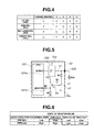
- FIG. 4 is an actuation table of the solenoids of the automatic transmission which employs the control apparatus according to the first embodiment of the present invention.
- FIG. 5 is a schematic view showing a solenoid failure sensing circuit in the control apparatus according to the first embodiment of the present invention.
- FIG. 6 is a table showing a sensing logic in the solenoid failure sensing circuit of FIG. 5 .
- FIG. 7 is a table showing a relationship between failure patterns and transmission states of the automatic transmission according to the first embodiment.
- FIG. 8 is a flowchart showing a failure shift control operation of the control apparatus according to the first embodiment of the present invention.
- FIG. 9 is a table showing a relationship between failure patterns and transmission states of an automatic transmission according to a second embodiment of the present invention.
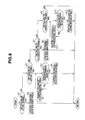
- FIG. 10 is a flowchart showing a failure shift control operation of the control apparatus according to the second embodiment of the present invention.
- FIG. 1 is a skeleton diagram showing a power train 6 of an automatic transmission AT which employs a control apparatus of an automatic transmission according to a first embodiment of the present invention.
- Power train 6 of automatic transmission AT includes a front planetary gear FPG which is a single pinion type, and a rear planetary gear RPG which is a single pinion type.
- power train 6 includes a low clutch L/C, a low and reverse brake L&R/B, a 2-4 brake 2-4/B, a reverse clutch REV/C, a high clutch H/C which are frictional engagement elements, and a one-way clutch OWC disposed in parallel with low and reverse brake L&R/B.
- Front planetary gear FPG includes a front sun gear FS, a front ring gear FR, a front pinion FP engaged with front sun gear FS and front ring gear FR, and a front career FC supporting front pinion FP.
- Rear planetary gear RPG includes a rear sun gear RS, a rear ring gear RR, a rear pinion gear RP engaged with rear sun gear RS and rear ring gear RR, and a rear career RC supporting rear pinion gear RP.
- Front career FC and rear ring gear RR are integrally connected with each other by a first rotation member M1.
- Front ring gear FR and rear career RC are integrally connected with each other by a second rotation member M2.
- power train 6 has a structure having four rotational elements (front sun gear FS, rear sun gear RS, first rotation member M1 and second rotation member M2) which are obtained by subtracting two rotational elements from six rotational elements.
- Front sun gear FS is arranged to be connected or disconnected through reverse clutch REV/C to a transmission input shaft 4.
- Front sun gear FS is arranged to be fixed through 2-4 brake 2-4/B to a transaxle case 3.
- Rear sun gear RS is arranged to be connected or disconnected through low clutch L/C to transmission input shaft 4.
- First rotation member M1 is arranged to be fixed through low and reverse brake L&R/B to transaxle case 3.
- First rotation member M1 is arranged to be connected or disconnected through high clutch H/C to transmission input shaft 4.
- Second rotation member M2 is connected directly to a transmission output gear 5.
- FIG. 2 is a hydraulic control system diagram showing an electronic shift control system and a hydraulic control circuit for a plurality of frictional engagement elements in a hydraulic control apparatus according to the first embodiment.
- the hydraulic control circuit includes a manual valve 20, a low clutch pressure regulating valve 21, a low clutch accumulator 22, a 2-4 brake pressure regulating valve 23, a 2-4 brake accumulator 24, a sharing (dual-purpose) pressure regulating valve 25, a switching valve 26, a switching signal valve 27, a high clutch inhibitor valve 28, a high clutch accumulator 29, and a low and reverse brake accumulator 30.
- the hydraulic control circuit includes a line pressure hydraulic passage 31, a pilot pressure hydraulic passage 32, a D range pressure hydraulic passage 33, an R range pressure hydraulic passage 34, a low clutch pressure hydraulic passage 35, a 2-4 brake pressure hydraulic passage 36, a sharing pressure output hydraulic passage 37, a first high clutch pressure hydraulic passage 38, a second high clutch pressure hydraulic passage 39, and a low and reverse brake pressure hydraulic passage 40.
- Manual valve 20 is a manual operation valve which is operated (activated) by the driver's operation of a select lever 41.
- Select lever 41 includes a D range configured to attain shift stages (gear stages) from a first speed to a fourth speed (the engine braking is not actuated at the first speed), a second range configured to attain the first speed and the second speed (the engine braking is actuated at the first speed), an R range configured to attain a reverse shift stage, a neutral range configured to release all of the clutches, and a parking range.
- manual valve 20 is arranged to introduce line pressure PL from line pressure hydraulic passage 31 to D range pressure hydraulic passage 33 when the D range is selected, and to introduce the line pressure PL from line pressure hydraulic passage 31 to R range pressure hydraulic passage 34 when the R range is selected.
- Low clutch pressure regulating valve 21 includes a low clutch solenoid L/C SOL.
- Low clutch pressure regulating valve 21 is a 3-way large capacity linear solenoid valve having a characteristic of a normal high.
- the normal high represents a setting in which the hydraulic pressure is supplied when the solenoid is switched to the OFF state.
- 2-4 brake pressure regulating valve 23 includes a 2-4 brake solenoid 24/B SOL.
- 2-4 brake pressure regulating valve 23 is a 3-way large capacity linear solenoid valve having a characteristic of a normal low.
- the normal low represents a setting in which the hydraulic pressure is not supplied when the solenoid is switched to the OFF state.
- 2-4 brake pressure which is obtained by regulating D range pressure PD from D range pressure hydraulic passage 33 as a source pressure is introduced through 2-4 brake pressure hydraulic passage 36 to 2-4 brake 2-4/B.
- 2-4 brake pressure supplied to 2-4 brake 2-4/B is drained.
- Sharing pressure regulating valve 25 includes a sharing solenoid H/C-L&R/B SOL.
- Sharing pressure regulating valve 25 is a 3-way large capacity linear solenoid valve having the characteristic of the normal high to generate the hydraulic pressure in the power OFF state.
- sharing pressure regulating valve 25 is arranged to regulate, through switching valve 26, the hydraulic pressures of two frictional engagement elements of high clutch H/C and low and reverse brake L&R/B.
- High clutch H/C of the two frictional engagement elements is arranged to connect transmission input shaft 4 and first rotation member M1 which is other than transmission output gear 5 that is a transmission output member.
- High clutch H/C is arranged to rotate by the torque of transmission input shaft 4 of first rotation member M1 when high clutch H/C is engaged during the idling state at the N range (neutral range) in a state in which transmission output gear 5 is fixed by a depression of a brake pedal (not shown) and so on.
- Switching valve 26 is arranged to switch a connection between hydraulic passages by a switching signal hydraulic pressure from a switching signal valve 27.
- Switching valve 27 includes an ON/OFF solenoid ON/OFF which is a solenoid valve having a characteristic (property) (hereinafter, referred to as the normal low) in which the hydraulic pressure is not produced in the power OFF state.
- Switching valve 26 is arranged to supply the hydraulic pressure generated from sharing pressure regulating valve 25 to high clutch H/C when switching signal valve 27 is the OFF state (the switching signal hydraulic pressure is not generated) at the selection of the D range (forward range).
- switching valve 26 is arranged to supply the hydraulic pressure from sharing pressure regulating valve 25 to low and reverse brake L&R/B when switching signal valve is in the ON state (the switching signal hydraulic pressure is generated) at the shift at the selection of the R range (reverse shift range). Moreover, switching valve 26 is arranged to open a portion which is for supplying R range pressure PR that is from manual valve 20, and that is generated at the R range, when switching signal valve 27 is in the OFF state and switching signal valve 27 is in a position to supply the hydraulic pressure generated from sharing pressure regulating valve 25, to high clutch inhibitor valve 28. High clutch inhibitor valve 28 is disposed between switching valve 26 and high clutch H/C.
- High clutch inhibitor valve 28 is arranged to be switched by receiving, as a signal pressure, D range pressure PD generated at the selection of the D range. High clutch inhibitor valve 28 is arranged to close a portion between sharing pressure regulating valve 25 and high clutch H/C when D range pressure PD is not acted.
- FIG. 3 is an engagement table showing engagement states of the frictional engagement elements at each shift stages of the automatic transmission which employs the control apparatus according to the first embodiment of the present invention.
- ⁇ represents an engaged state in which the corresponding frictional engagement element is engaged.
- ⁇ represents an energization state in which the corresponding one of the solenoids is energized (the current is applied to the corresponding one of the solenoids).
- the forward four speeds and the reverse speed are attained by a changeover shift.
- the changeover shift is attained by disengaging an engaged frictional engagement element of the frictional engagement elements provided in the power train, and by engaging a disengaged frictional engagement element of the frictional engagement elements.
- the "first speed” at which the engine braking is actuated is attained by engaging low clutch L/C and low and reverse brake L&R/B.
- the only ON/OFF solenoid ON/OFF SOL is switched to the ON state, and the other solenoids are switched to the OFF state.
- the "first speed” at which the engine braking is not actuated is attained by engaging only low clutch L/C.
- the only sharing solenoids H/C-L&R/B SOL is switched to the ON state, and the other solenoids are switched to the OFF state.
- the "second speed” is attained by engaging low clutch L/C and 2-4 brake 2-4/B.
- 2-4 brake solenoid 24/B SOL and sharing solenoid H/C-L&R/B SOL are switched to the ON state, and the other solenoids are switched to the OFF state.
- the "third speed” is attained by engaging low clutch L/C and high clutch H/C. In this case, all of the solenoids are switched to the OFF state.
- the "fourth speed” is attained by engaging high clutch H/C and 2-4 brake 2-4/B.
- low clutch solenoid L/C SOL and 2-4 brake solenoid 24/B SOL are switched to the ON state, and the other solenoids are switched to the OFF state.
- the "reverse speed” is attained by engaging reverse clutch REV/C and low and reverse brake L&R/B. In this case, manual valve 20 is switched to the R range in a mechanical manner (by the driver's operation). Accordingly, the "reverse speed” is attained in a state in which all of the solenoids are in the OFF state.
- the electronic shift control system includes an accelerator opening sensor 50, a vehicle speed sensor 51, other sensors 52 (transmission input rotational speed sensor, inhibitor switch and so on), and an AT control unit 53.
- AT control unit 53 receives an information (signal) from accelerator opening sensor 50, an information (signal) from vehicle speed sensor 51, and an information (signals) from other sensors 52.
- AT control unit 53 is configured to seek an appropriate shift stage from a position of a driving point in a shift map, which is determined by accelerator opening APO and vehicle speed VSP, for example, when the vehicle runs at the selection of the D range.
- AT control unit 53 is configured to output a control command for obtaining the sought shift stage, to the solenoids.
- the shift map sets an upshift line and a downshift line in accordance with the driving point determined by the accelerator opening and the vehicle speed.
- AT control unit 53 includes a solenoid failure sensing circuit 53a configured to sense an OFF failure (malfunction) of each of the solenoids, and a failure shift control section 53b (failure shift stage setting section) configured to set, to the target shift stage, the shift stage which can be attained in a state in which the solenoid judged that the failure is generated is not energized, in accordance with the sensed failure, and to perform various failure shift control operations.
- failure shift control section 53b is configured to perform a failure neutral state through control operation to switch to the neutral state when a predetermined condition is satisfied in a case in which the vehicle speed may be suddenly decreased when (if) the target shift stage set at the failure (hereinafter, referred to as the failure target shift stage) is attained.
- failure shift control section 53b is configured to perform a failure shift control operation to shift to the target shift stage, irrespective of the satisfaction of the predetermined conditions in a case in which the vehicle speed is not suddenly decreased when the failure target shift stage is attained.
- FIG. 5 is a schematic diagram showing solenoid failure sensing circuit 53a according to the first embodiment.
- the schematic diagram shows one solenoid as example.
- each of the solenoids has an identical structure shown in FIG. 5 .
- AT control unit 53 includes a CPU 531 having a predetermined control program and so on.
- This CPU 531 includes an output port 531a configured to output a driving command, and a monitor port 531b configured to sense the energization to the solenoid.
- the signal from output port 531a is outputted to a driving circuit 532.
- Driving circuit 532 is configured to convert a battery supply Vbatt to a predetermined voltage based on the driving signal from CPU 531, and to output this through a driving voltage supply circuit a1 to the solenoid.
- Driving voltage supply circuit a1 and the solenoid are connected with each other by a connector 533.
- a monitor circuit b1 is connected between driving voltage supply circuit a1 and monitor port 531b.
- Monitor circuit b1 includes resistors R1, R2, R3 and R4, and a transistor TR. Resistor R1 and R2 are set to voltages which can be sensed in monitor port 531b.
- Transistor TR is connected with an ignition power supply VIGN.
- the resistor value of resistor R3 and the resistor value of resistor R4 are set so that a base-emitter voltage to switch transistor TR to the OFF state is obtained when the output state from output port 531a is in the ON state, and so that the base-emitter voltage to switch transistor TR to the ON state is obtained when the solenoid is in the OFF state.
- FIG. 6 is a table showing a sensing logic in the solenoid failure sensing circuit according to the first embodiment.
- the ON signal that is, the High level signal
- the Low level signal of the monitor value is sensed in the normal state.
- the OFF signal that is, the Low level signal
- the High level signal of the monitor value is sensed in the normal state.
- GND short When the solenoid is grounded (hereinafter, referred to as GND short), the current constantly flows in resistor R4 from ignition power supply VIGN connected with transistor TR. With this, the base voltage of transistor TR is lowered, and transistor TR is brought to the ON state.
- the monitor signal becomes the High level, irrespective of the High level or the Low level of the driving signal.
- Open circuit When the solenoid is broken or disconnected (hereinafter, referred to as Open circuit), or when the solenoid is short-circuited (connected) directly to battery supply Vbatt (hereinafter, referred to as Vbatt short), the current does not flow in resistor R4 from ignition power supply VIGN of the monitor circuit. With this, the base voltage of transistor TR is increased, and transistor TR becomes the OFF state. Accordingly, the monitor signal becomes the Low level, irrespective of the High level or the Low level of the driving signal.
- the abnormal condition (failure) is not judged when the output state from CPU 531 is in the OFF state (the Low level), and also the monitor value represents the High level.
- the GND short is generated when the output state from CPU 531 is in the ON state (the High level), and also the monitor value represents the High level.
- the abnormal condition (failure) is not judged when the output state from CPU 531 is in the ON state (the High level), and also the monitor value represents the Low level.
- the Open circuit or the Vbatt short is generated when the output state from CPU 531 is in the OFF state (the Low level), and also the monitor value is in the Low level. That is, in the solenoid failure sensing circuit according to the first embodiment, it is not possible to distinguish between the Open circuit and the Vbatt short.
- the Vbatt short is extremely less frequently generated. Therefore, it is possible to suppress the increase of the cost by excluding the sensing circuit of the Vbatt short.
- FIG. 7 is a table showing a relationship between failure patterns and transmission states in the automatic transmission according to the first embodiment of the present invention.
- CPU 531 senses the OFF failure of the solenoid
- the solenoid is energized. Accordingly, there is a problem that the discerned failure state is different from the actual actuation state.
- the solenoid failures are illustrated.
- the interlock When the command of the fourth speed is outputted, the interlock is generated. This is because the hydraulic pressure is not supplied to low and reverse brake L&R/B if the D range is selected even when the signal of the ON/OFF solenoid ON/OFF SOL is outputted. Accordingly, the second speed which is not influenced in any cases is set as the failure target shift stage.
- the vehicle speed when the transmission gear ratio is fixed to the second speed, the vehicle speed may be suddenly decreased at some vehicle speed by the large engine braking. Accordingly, when the vehicle speed is higher than a predetermined value A2 (>A1) representing a vehicle speed at which the sudden speed decrease is not generated at the second speed, the vehicle is brought to the neutral state once. Then, when the vehicle speed is equal to or smaller than predetermined value A2, the second speed is selected as the failure target shift stage.
- FIG. 8 is a flowchart showing the failure shift control operation in the control apparatus according to the first embodiment of the present invention.
- step S1 it is judged whether or not the OFF failure that low clutch solenoid L/C SOL can not be energized is generated.
- step S2 the solenoids are controlled to attain the third speed.
- step S3 the process proceeds to step S3.
- step S3 it is judged whether or not the OFF failure that 2-4 brake solenoid 24/B SOL can not be energized is generated.
- step S3 it is judged whether or not the OFF failure that 2-4 brake solenoid 24/B SOL can not be energized is generated.
- step S3 it is judged whether or not the OFF failure that 2-4 brake solenoid 24/B SOL can not be energized is generated.
- step S3 is affirmative (YES)
- step S7 it is judged whether or not vehicle speed V is smaller than predetermined value A1.
- step S6 the solenoids are controlled to attain the third speed.
- step S5 the solenoids are controlled to attain the neutral state.
- This predetermined value A1 is set to a predetermined extreme low vehicle speed at which the sudden speed decrease is not generated even when the vehicle is shifted to the third speed at the generation of the Vbatt short and accordingly the interlock is generated.
- the activation states of the solenoids are set so that all of low clutch L/C, high clutch H/C, low and reverse brake L&R/B, and reverse clutch REV/C are disengaged. With this, even when 2-4 brake 2-4/B is engaged, it is possible to attain the neutral state.
- all of the solenoids are switched to the OFF state.
- step S7 it is judged whether or not the OFF failure that sharing solenoid H/C-L&R/B SOL can not be energized is generated.
- step S7 the answer of step S7 is affirmative (YES)
- step S8 the solenoids are controlled to attain the third speed.
- step S9 the process proceeds to step S9.
- step S9 it is judged whether or not the OFF failure that ON/OFF solenoid ON/OFF SOL can not be energized is generated.
- step S9 it is judged whether or not the OFF failure that ON/OFF solenoid ON/OFF SOL can not be energized is generated.
- step S9 it is judged whether or not the OFF failure that ON/OFF solenoid ON/OFF SOL can not be energized is generated.
- step S9 it is judged whether or not the OFF failure that ON/OFF solenoid ON/OFF SOL can not be energized is generated.
- step S10 it is judged whether or not the vehicle speed V is smaller than predetermined value A2.
- step S!2 the solenoids are controlled to attain the second speed.
- step S11 the solenoids are controlled to attain the neutral state. For attaining the neutral state, the activation states of the solenoids are set so that all of the engagement elements are disengaged.
- This predetermined value A2 is a vehicle speed such that the sudden vehicle speed decrease is not generated by the excessive engine braking force when the vehicle is shifted to the second speed. Accordingly, it is possible to shift to the second speed, irrespective of the generation of the Vbatt short.
- the answer of step S9 is negative (NO)
- the OFF failure is not sensed in all of the solenoids, and the process is finished.
- An control apparatus for an automatic transmission arranged to selectively engage a plurality of frictional engagement elements by controlling driving states or non-driving states of the plurality of solenoids so as to attain a predetermined target shift stage
- the control apparatus includes: a failure judging section (53a, 53b) configured to judge one of the solenoids in which a failure that the one of the solenoids is not energized is generated; a failure shift stage setting section (53b; S2, S6, S8, S12) configured to set, to the target shift stage, a shift stage which can be attained in a state in which the one of the solenoids judged that the failure is generated is not energized when the failure judging section (53a, 53b) judges the failure of the one of the solenoids; a failure neutral state through section (S4, S5, S6 or step S10, S11, S12) configured to control the driving states or the non-driving states of the pluralit
- the failure target shift stage set at the failure of the solenoid is not the shift stage at which the vehicle speed may be suddenly decreased, it is possible to rapidly ensure the driving force of the vehicle by controlling the driving states or the non-driving states of the plurality of the solenoids so that automatic transmission AT attains the failure target shift stage, irrespective of the vehicle speed.
- the failure neutral state through section (53b, step S4, S5, S6 or S10, S11, S12) is configured to control the driving states or the non-driving states of the plurality of the solenoids at the vehicle speed equal to or greater than the predetermined value (A1 or A2) so that the automatic transmission is brought to the neutral state, when the target shift stage set by the failure shift stage setting section (53b) is the shift stage at which the vehicle speed is suddenly decreased when the one of the solenoids judged that the failure is generated is energized when the automatic transmission attains the target shift stage, and to control the driving states or the non-driving states of the plurality of the solenoids at the vehicle speed smaller than the predetermined value (A1 or A2) so that the automatic transmission attains the target shift stage set by the failure shift stage setting section (53b), when the target shift stage set by the failure shift stage setting section (53b) is the shift stage at which the vehicle speed is suddenly decreased when the one of the solenoids judged that the failure is generated is energized when the automatic
- the failure target shift stage set at the failure of the solenoid is not the shift stage at which the vehicle speed is not suddenly decreased, it is possible to rapidly ensure the driving force of the vehicle by controlling the driving states or the non-driving states of the plurality of the solenoids so that automatic transmission AT attains the failure target shift stage, irrespective of the vehicle speed.
- the failure neutral state through section (53b, step S4, S5, S6 or S10, S11, S12) is configured to control the driving states or the non-driving states of the plurality of the solenoids at a vehicle speed equal to or greater than a predetermined value (A1) so that the automatic transmission is brought to the neutral state, when the target shift stage (3rd) set by the failure shift stage setting section (53b) is a shift stage at which the automatic transmission (AT) is interlocked when the one of the solenoids (24B SOL) judged that the failure is generated is energized when the automatic transmission (AT) attains the target shift stage, and to control the driving states or the non-driving states of the plurality of the solenoids at a vehicle speed smaller than the predetermined value (A1) so that the automatic transmission (AT) attains the target shift stage set by the failure shift stage setting section (53b), when the target shift stage (3rd) set by the failure shift stage setting section (53b) is a shift stage at which the automatic transmission (AT)
- FIG. 9 is a table showing a relationship between failure patterns and transmission states of the automatic transmission according to the second embodiment of the present invention.
- the control apparatus according to the first embodiment at the OFF failure of ON/OFF solenoid ON/OFF SOL, the second speed is selected as the failure target shift stage after via the neutral state.
- the third speed is selected as the failure target shift stage after via the neutral state, unlike the first embodiment.
- the interlock is caused. This is because the hydraulic pressure is not supplied to low and reverse brake L&R/B if the D range is selected even when the signal of ON/OFF solenoid ON/OFF SOL is outputted.
- the third speed can respond to the various running circumstances relative to the second speed.
- provability that the Vbatt short is generated is extremely low. Accordingly, the failure target shift stage is set to the third speed. In this case, if the Vbatt short is generated, the first speed (with the engine braking) is selected (attained). Accordingly, the sudden vehicle speed decrease may be generated by the excessive engine braking at some vehicle speeds.
- the vehicle speed is higher than a predetermined value A3 ( ⁇ A2) representing a vehicle speed at which the sudden vehicle speed decrease is not generated, the vehicle is brought to the neutral state once, and then the third speed is selected as the failure target shift stage at the low vehicle speed equal to or smaller than the predetermined value A3.
- FIG. 10 is a flowchart showing a failure shift control operation according to the second embodiment of the present invention.
- Steps S1-S9 are identical to the steps S1-S9 of the first embodiment. Steps after step S9 are illustrated below.
- step S9 it is judged whether or not the OFF failure that ON/OFF solenoid ON/OFF SOL can not be energized is generated.
- step S101 it is judged whether or not vehicle speed V is smaller than predetermined value A3.
- the process proceeds to step S121.
- step S121 the solenoids are controlled to attain the third speed.
- step S101 is negative (NO)
- step S101 the answer of step S101 is negative (NO)
- step S11 the solenoids are controlled to attain the neutral state.
- the activation states of the solenoids are set so that all of the engagement elements are disengaged. With this, even when low and reverse brake L&R/B is engaged, it is possible to attain the neutral state if the other frictional engagement elements are disengaged.
- This predetermined value A3 is a vehicle speed at which the sudden vehicle speed decrease is not generated by the excessive engine braking force even when the first speed (with the engine braking) is selected when the shift stage is shifted to the third speed.
- step S9 negative (NO)
- the OFF failures of all of the solenoids are not detected, and the process is finished.
- the failure neutral state through section (53b; S4, S5, S6 or S10, S11, S12) is configured to control the driving states or the non-driving states of the plurality of the solenoids at a vehicle speed equal to or greater than a predetermined value (A3) so that the automatic transmission (AT) is brought to the neutral state, when the target shift stage (3rd) set by the failure shift stage setting section (53b) is a first speed which is a maximum transmission ratio, and at which the engine braking is generated in the vehicle when the one of the solenoids (OM/OFF SOL) judged that the failure is generated is energized when the automatic transmission (AT) attains the target shift stage (3rd), and to control the driving states or the non-driving states of the plurality of the solenoids at a vehicle speed smaller than the predetermined value (A3) so that the automatic transmission attains the target shift stage (3rd) set by the failure shift stage setting section (53b), when the target shift stage (3rd) set by the failure shift stage setting section
- the failure target shift stage is not the shift stage at which the excessive engine braking is not generated, it is possible to rapidly ensure the driving force of the vehicle by controlling the driving states or the non-driving states of the plurality of the solenoids so that automatic transmission AT attains the failure target shift stage, irrespective of the vehicle speed.
- the present invention has been described above by reference to the first and second embodiments of the invention. Moreover, the present invention includes an example described below even when the structure is different from the structures of the first and second embodiments.
- the present invention is applied to the automatic transmission in which the four frictional engagement elements are selectively engaged by controlling the driving states and the non-driving states of the four solenoids to attain the four shift stages.
- the present invention is not limited to this structure.
- the present invention is applicable to an automatic transmission configured to attain a plurality of shift stages by selectively engaging the plurality of the frictional engagement elements by controlling the driving states and the non-driving states of the plurality of the solenoids, irrespective of the number of the solenoids, the number of the frictional engagement elements, and the number of the shift stages.
- the shift stage is fixed to the predetermined shift stage at the failure of the solenoid.
- the present invention is not limited to this structure.
- the shift control may be performed between the first speed and the third speed. That is, the shift control may be continued between the shift stages which can be attained even at the failure state of the solenoid judged that there is the failure.
- the present invention is applicable to an automatic transmission in which the shift stage is not fixed to a predetermined shift stage at the judgment of the failure.
- the threshold values of the vehicle speeds for releasing the neutral state are set to A1 ⁇ A2.
- these values are set independently.
- the shift stage when the OFF failure is sensed in the solenoid which performs the shift control of the automatic transmission, the shift stage is shifted to the failure target shift stage.
- the sudden vehicle speed decrease may be generated at the generation of the short-circuited failure of the solenoid in a case in which the failure target shift stage is selected
- the automatic transmission is brought to the neutral state until the vehicle speed is decreased to the predetermined value, and then the shift is performed.
- the shift stage is shifted to the failure target shift stage, irrespective of the vehicle speed.
- the failure target shift stage set at the failure of the solenoid is not the shift stage at which the vehicle speed may be suddenly decreased, it is possible to rapidly ensure the driving force of the vehicle by controlling the driving states and the non-driving states of the plurality of the solenoids so that the automatic transmission attains the failure target shift stage, irrespective of the vehicle speed.
Abstract
Description
- This invention relates to a control apparatus for an automatic transmission arranged to shift by actuations of a plurality of solenoids.
-
U.S. Patent No. 6,223,113 (corresponding to Japanese Patent Application Publication No.2000-161480 - However, the above-described apparatus needs a new (special) circuit for sensing a short failure (short-circuit failure) to a battery. Accordingly, the cost is increased.
- It is, therefore, an object of the present invention to provide a control apparatus for an automatic transmission which is devised to solve the above mentioned problem, to suppress an increase of a cost, and to ensure a safety by sensing a failure of a short-circuit to a battery.
- According to one aspect of the present invention, an control apparatus for an automatic transmission arranged to selectively engage a plurality of frictional engagement elements by controlling driving states or non-driving states of the plurality of solenoids so as to attain a predetermined target shift stage, the control apparatus comprises: a failure judging section configured to judge one of the solenoids in which a failure that the one of the solenoids is not energized is generated; a failure shift stage setting section configured to set, to the target shift stage, a shift stage which can be attained in a state in which the one of the solenoids judged that the failure is generated is not energized when the failure judging section judges the failure of the one of the solenoids; a failure neutral state through section configured to control the driving states or the non-driving states of the plurality of the solenoids at a vehicle speed equal to or greater than a predetermined value so that the automatic transmission is brought to a neutral state, when the target shift stage set by the failure shift stage setting section is a shift stage at which the vehicle speed is suddenly decreased when the driving states or the non-driving states of the solenoids are controlled so that the automatic transmission attains the target shift stage set by the failure shift stage setting section, and to control the driving states or the non-driving states of the plurality of the solenoids at a vehicle speed smaller than the predetermined value so that the automatic transmission attains the target shift stage set by the failure shift stage setting section, when the target shift stage set by the failure shift stage setting section is a shift stage at which the vehicle speed is suddenly decreased when the driving states or the non-driving states of the solenoids are controlled so that the automatic transmission attains the target shift stage set by the failure shift stage setting section; and a failure shift section configured to control the driving states or the non-driving states of the plurality of the solenoids irrespective of the vehicle speed so that the automatic transmission attains the target shift stage set by the failure shift stage setting section when the target shift stage set by the failure shift stage setting section is not the shift stage at which the vehicle speed is suddenly decreased when the driving states or the non-driving states of the plurality of the solenoids are controlled so that the automatic transmission attains the target shift stage set by the failure shift stage setting section.
-
FIG. 1 is a skeleton diagram showing a power train of an automatic transmission which employs an control apparatus of an automatic transmission according to a first embodiment of the present invention. -
FIG. 2 is a hydraulic control system diagram showing an electronic shift control system and a hydraulic control circuit for a plurality of frictional engagement elements in a hydraulic control apparatus according to the first embodiment of the present invention. -
FIG. 3 is an engagement table showing engagement states of frictional engagement elements at each shift stage of the automatic transmission which employs the control apparatus according to the first embodiment of the present invention. -
FIG. 4 is an actuation table of the solenoids of the automatic transmission which employs the control apparatus according to the first embodiment of the present invention. -
FIG. 5 is a schematic view showing a solenoid failure sensing circuit in the control apparatus according to the first embodiment of the present invention. -
FIG. 6 is a table showing a sensing logic in the solenoid failure sensing circuit ofFIG. 5 . -
FIG. 7 is a table showing a relationship between failure patterns and transmission states of the automatic transmission according to the first embodiment. -
FIG. 8 is a flowchart showing a failure shift control operation of the control apparatus according to the first embodiment of the present invention. -
FIG. 9 is a table showing a relationship between failure patterns and transmission states of an automatic transmission according to a second embodiment of the present invention. -
FIG. 10 is a flowchart showing a failure shift control operation of the control apparatus according to the second embodiment of the present invention. -
FIG. 1 is a skeleton diagram showing apower train 6 of an automatic transmission AT which employs a control apparatus of an automatic transmission according to a first embodiment of the present invention. Hereinafter, a structure of thepower train 6 is illustrated with reference toFIG. 1 .Power train 6 of automatic transmission AT includes a front planetary gear FPG which is a single pinion type, and a rear planetary gear RPG which is a single pinion type. Moreover,power train 6 includes a low clutch L/C, a low and reverse brake L&R/B, a 2-4 brake 2-4/B, a reverse clutch REV/C, a high clutch H/C which are frictional engagement elements, and a one-way clutch OWC disposed in parallel with low and reverse brake L&R/B. Front planetary gear FPG includes a front sun gear FS, a front ring gear FR, a front pinion FP engaged with front sun gear FS and front ring gear FR, and a front career FC supporting front pinion FP. Rear planetary gear RPG includes a rear sun gear RS, a rear ring gear RR, a rear pinion gear RP engaged with rear sun gear RS and rear ring gear RR, and a rear career RC supporting rear pinion gear RP. - Front career FC and rear ring gear RR are integrally connected with each other by a first rotation member M1. Front ring gear FR and rear career RC are integrally connected with each other by a second rotation member M2. Accordingly, by combining front planetary gear FPG and rear planetary gear RPG,
power train 6 has a structure having four rotational elements (front sun gear FS, rear sun gear RS, first rotation member M1 and second rotation member M2) which are obtained by subtracting two rotational elements from six rotational elements. Front sun gear FS is arranged to be connected or disconnected through reverse clutch REV/C to atransmission input shaft 4. Front sun gear FS is arranged to be fixed through 2-4 brake 2-4/B to atransaxle case 3. Rear sun gear RS is arranged to be connected or disconnected through low clutch L/C totransmission input shaft 4. First rotation member M1 is arranged to be fixed through low and reverse brake L&R/B totransaxle case 3. First rotation member M1 is arranged to be connected or disconnected through high clutch H/C totransmission input shaft 4. Second rotation member M2 is connected directly to atransmission output gear 5. -
FIG. 2 is a hydraulic control system diagram showing an electronic shift control system and a hydraulic control circuit for a plurality of frictional engagement elements in a hydraulic control apparatus according to the first embodiment. Hereinafter, a structure of the hydraulic control system is illustrated with reference toFIG. 2 . As shown inFIG. 2 , the hydraulic control circuit includes amanual valve 20, a low clutchpressure regulating valve 21, alow clutch accumulator 22, a 2-4 brakepressure regulating valve 23, a 2-4brake accumulator 24, a sharing (dual-purpose)pressure regulating valve 25, aswitching valve 26, aswitching signal valve 27, a highclutch inhibitor valve 28, ahigh clutch accumulator 29, and a low andreverse brake accumulator 30. Moreover, the hydraulic control circuit includes a line pressurehydraulic passage 31, a pilot pressurehydraulic passage 32, a D range pressurehydraulic passage 33, an R range pressurehydraulic passage 34, a low clutch pressurehydraulic passage 35, a 2-4 brake pressurehydraulic passage 36, a sharing pressure outputhydraulic passage 37, a first high clutch pressurehydraulic passage 38, a second high clutch pressurehydraulic passage 39, and a low and reverse brake pressurehydraulic passage 40. -
Manual valve 20 is a manual operation valve which is operated (activated) by the driver's operation of aselect lever 41.Select lever 41 includes a D range configured to attain shift stages (gear stages) from a first speed to a fourth speed (the engine braking is not actuated at the first speed), a second range configured to attain the first speed and the second speed (the engine braking is actuated at the first speed), an R range configured to attain a reverse shift stage, a neutral range configured to release all of the clutches, and a parking range. For example,manual valve 20 is arranged to introduce line pressure PL from line pressurehydraulic passage 31 to D range pressurehydraulic passage 33 when the D range is selected, and to introduce the line pressure PL from line pressurehydraulic passage 31 to R range pressurehydraulic passage 34 when the R range is selected. - Low clutch
pressure regulating valve 21 includes a low clutch solenoid L/C SOL. Low clutchpressure regulating valve 21 is a 3-way large capacity linear solenoid valve having a characteristic of a normal high.
The normal high represents a setting in which the hydraulic pressure is supplied when the solenoid is switched to the OFF state. When low clutch solenoid L/C SOL is disengaged, the low clutch pressure supplied to low clutch L/C is drained by switching low clutch solenoid L/C SOL to the ON state. 2-4 brakepressure regulating valve 23 includes a 2-4brake solenoid 24/B SOL. 2-4 brakepressure regulating valve 23 is a 3-way large capacity linear solenoid valve having a characteristic of a normal low. The normal low represents a setting in which the hydraulic pressure is not supplied when the solenoid is switched to the OFF state. At the engagement of 2-4 brake 2-4/B, 2-4 brake pressure which is obtained by regulating D range pressure PD from D range pressurehydraulic passage 33 as a source pressure is introduced through 2-4 brake pressurehydraulic passage 36 to 2-4 brake 2-4/B. At the disengagement of 2-4 brake 2-4/B, 2-4 brake pressure supplied to 2-4 brake 2-4/B is drained. - Sharing
pressure regulating valve 25 includes a sharing solenoid H/C-L&R/B SOL. Sharingpressure regulating valve 25 is a 3-way large capacity linear solenoid valve having the characteristic of the normal high to generate the hydraulic pressure in the power OFF state. By the hydraulic pressure obtained by regulating the hydraulic pressure (line pressure PL) supplied without throughmanual valve 20 as the source pressure, sharingpressure regulating valve 25 is arranged to regulate, through switchingvalve 26, the hydraulic pressures of two frictional engagement elements of high clutch H/C and low and reverse brake L&R/B. High clutch H/C of the two frictional engagement elements is arranged to connecttransmission input shaft 4 and first rotation member M1 which is other thantransmission output gear 5 that is a transmission output member. High clutch H/C is arranged to rotate by the torque oftransmission input shaft 4 of first rotation member M1 when high clutch H/C is engaged during the idling state at the N range (neutral range) in a state in whichtransmission output gear 5 is fixed by a depression of a brake pedal (not shown) and so on. - Switching
valve 26 is arranged to switch a connection between hydraulic passages by a switching signal hydraulic pressure from aswitching signal valve 27. Switchingvalve 27 includes an ON/OFF solenoid ON/OFF which is a solenoid valve having a characteristic (property) (hereinafter, referred to as the normal low) in which the hydraulic pressure is not produced in the power OFF state.Switching valve 26 is arranged to supply the hydraulic pressure generated from sharingpressure regulating valve 25 to high clutch H/C when switchingsignal valve 27 is the OFF state (the switching signal hydraulic pressure is not generated) at the selection of the D range (forward range). On the other hand, switchingvalve 26 is arranged to supply the hydraulic pressure from sharingpressure regulating valve 25 to low and reverse brake L&R/B when switching signal valve is in the ON state (the switching signal hydraulic pressure is generated) at the shift at the selection of the R range (reverse shift range). Moreover, switchingvalve 26 is arranged to open a portion which is for supplying R range pressure PR that is frommanual valve 20, and that is generated at the R range, when switchingsignal valve 27 is in the OFF state and switchingsignal valve 27 is in a position to supply the hydraulic pressure generated from sharingpressure regulating valve 25, to highclutch inhibitor valve 28. Highclutch inhibitor valve 28 is disposed between switchingvalve 26 and high clutch H/C. Highclutch inhibitor valve 28 is arranged to be switched by receiving, as a signal pressure, D range pressure PD generated at the selection of the D range. Highclutch inhibitor valve 28 is arranged to close a portion between sharingpressure regulating valve 25 and high clutch H/C when D range pressure PD is not acted. -
FIG. 3 is an engagement table showing engagement states of the frictional engagement elements at each shift stages of the automatic transmission which employs the control apparatus according to the first embodiment of the present invention. InFIG. 3 , ○ represents an engaged state in which the corresponding frictional engagement element is engaged. InFIG. 4 , ○ represents an energization state in which the corresponding one of the solenoids is energized (the current is applied to the corresponding one of the solenoids). The forward four speeds and the reverse speed are attained by a changeover shift. The changeover shift is attained by disengaging an engaged frictional engagement element of the frictional engagement elements provided in the power train, and by engaging a disengaged frictional engagement element of the frictional engagement elements. - The "first speed" at which the engine braking is actuated is attained by engaging low clutch L/C and low and reverse brake L&R/B. In this case, the only ON/OFF solenoid ON/OFF SOL is switched to the ON state, and the other solenoids are switched to the OFF state. The "first speed" at which the engine braking is not actuated is attained by engaging only low clutch L/C. In this case, the only sharing solenoids H/C-L&R/B SOL is switched to the ON state, and the other solenoids are switched to the OFF state. The "second speed" is attained by engaging low clutch L/C and 2-4 brake 2-4/B. In this case, 2-4
brake solenoid 24/B SOL and sharing solenoid H/C-L&R/B SOL are switched to the ON state, and the other solenoids are switched to the OFF state. The "third speed" is attained by engaging low clutch L/C and high clutch H/C. In this case, all of the solenoids are switched to the OFF state. The "fourth speed" is attained by engaging high clutch H/C and 2-4 brake 2-4/B. In this case, low clutch solenoid L/C SOL and 2-4brake solenoid 24/B SOL are switched to the ON state, and the other solenoids are switched to the OFF state. The "reverse speed" is attained by engaging reverse clutch REV/C and low and reverse brake L&R/B. In this case,manual valve 20 is switched to the R range in a mechanical manner (by the driver's operation). Accordingly, the "reverse speed" is attained in a state in which all of the solenoids are in the OFF state. - The electronic shift control system includes an
accelerator opening sensor 50, avehicle speed sensor 51, other sensors 52 (transmission input rotational speed sensor, inhibitor switch and so on), and anAT control unit 53. ATcontrol unit 53 receives an information (signal) fromaccelerator opening sensor 50, an information (signal) fromvehicle speed sensor 51, and an information (signals) fromother sensors 52. ATcontrol unit 53 is configured to seek an appropriate shift stage from a position of a driving point in a shift map, which is determined by accelerator opening APO and vehicle speed VSP, for example, when the vehicle runs at the selection of the D range. ATcontrol unit 53 is configured to output a control command for obtaining the sought shift stage, to the solenoids. The shift map sets an upshift line and a downshift line in accordance with the driving point determined by the accelerator opening and the vehicle speed. - AT
control unit 53 includes a solenoidfailure sensing circuit 53a configured to sense an OFF failure (malfunction) of each of the solenoids, and a failureshift control section 53b (failure shift stage setting section) configured to set, to the target shift stage, the shift stage which can be attained in a state in which the solenoid judged that the failure is generated is not energized, in accordance with the sensed failure, and to perform various failure shift control operations. Moreover, failureshift control section 53b is configured to perform a failure neutral state through control operation to switch to the neutral state when a predetermined condition is satisfied in a case in which the vehicle speed may be suddenly decreased when (if) the target shift stage set at the failure (hereinafter, referred to as the failure target shift stage) is attained. Furthermore, failureshift control section 53b is configured to perform a failure shift control operation to shift to the target shift stage, irrespective of the satisfaction of the predetermined conditions in a case in which the vehicle speed is not suddenly decreased when the failure target shift stage is attained. - (Solenoid Failure Sensing Circuit) Next, the solenoid failure sensing circuit according to the first embodiment is illustrated.
FIG. 5 is a schematic diagram showing solenoidfailure sensing circuit 53a according to the first embodiment. The schematic diagram shows one solenoid as example. However, each of the solenoids has an identical structure shown inFIG. 5 . ATcontrol unit 53 includes aCPU 531 having a predetermined control program and so on. ThisCPU 531 includes anoutput port 531a configured to output a driving command, and amonitor port 531b configured to sense the energization to the solenoid. The signal fromoutput port 531a is outputted to adriving circuit 532. Drivingcircuit 532 is configured to convert a battery supply Vbatt to a predetermined voltage based on the driving signal fromCPU 531, and to output this through a driving voltage supply circuit a1 to the solenoid. Driving voltage supply circuit a1 and the solenoid are connected with each other by aconnector 533. A monitor circuit b1 is connected between driving voltage supply circuit a1 and monitorport 531b. Monitor circuit b1 includes resistors R1, R2, R3 and R4, and a transistor TR. Resistor R1 and R2 are set to voltages which can be sensed inmonitor port 531b. Transistor TR is connected with an ignition power supply VIGN. The resistor value of resistor R3 and the resistor value of resistor R4 are set so that a base-emitter voltage to switch transistor TR to the OFF state is obtained when the output state fromoutput port 531a is in the ON state, and so that the base-emitter voltage to switch transistor TR to the ON state is obtained when the solenoid is in the OFF state. -
FIG. 6 is a table showing a sensing logic in the solenoid failure sensing circuit according to the first embodiment. Whenoutput port 531a outputs the ON signal (that is, the High level signal), the Low level signal of the monitor value is sensed in the normal state. On the other hand, whenoutput port 531a outputs the OFF signal (that is, the Low level signal), the High level signal of the monitor value is sensed in the normal state. When the solenoid is grounded (hereinafter, referred to as GND short), the current constantly flows in resistor R4 from ignition power supply VIGN connected with transistor TR. With this, the base voltage of transistor TR is lowered, and transistor TR is brought to the ON state. Accordingly, the monitor signal becomes the High level, irrespective of the High level or the Low level of the driving signal. When the solenoid is broken or disconnected (hereinafter, referred to as Open circuit), or when the solenoid is short-circuited (connected) directly to battery supply Vbatt (hereinafter, referred to as Vbatt short), the current does not flow in resistor R4 from ignition power supply VIGN of the monitor circuit. With this, the base voltage of transistor TR is increased, and transistor TR becomes the OFF state. Accordingly, the monitor signal becomes the Low level, irrespective of the High level or the Low level of the driving signal. - In the above-described relationship, in the control apparatus according to the first embodiment, a judgment shown in a portion surrounded by a bold line of
FIG. 6 is performed. That is, the abnormal condition (failure) is not judged when the output state fromCPU 531 is in the OFF state (the Low level), and also the monitor value represents the High level. On the other hand, it is judged that the GND short is generated when the output state fromCPU 531 is in the ON state (the High level), and also the monitor value represents the High level. Moreover, the abnormal condition (failure) is not judged when the output state fromCPU 531 is in the ON state (the High level), and also the monitor value represents the Low level. On the other hand, it is judged that the Open circuit or the Vbatt short is generated when the output state fromCPU 531 is in the OFF state (the Low level), and also the monitor value is in the Low level. That is, in the solenoid failure sensing circuit according to the first embodiment, it is not possible to distinguish between the Open circuit and the Vbatt short. The Vbatt short is extremely less frequently generated. Therefore, it is possible to suppress the increase of the cost by excluding the sensing circuit of the Vbatt short. -
FIG. 7 is a table showing a relationship between failure patterns and transmission states in the automatic transmission according to the first embodiment of the present invention. As shown in the sensing logic ofFIG. 6 , even whenCPU 531 senses the OFF failure of the solenoid, it is not possible to distinguish between the Open circuit and the Vbatt short. At the Open circuit, there is no problem since the solenoid is not energized. However, at the Vbatt short, the solenoid is energized. Accordingly, there is a problem that the discerned failure state is different from the actual actuation state. Hereinafter, the solenoid failures are illustrated. - (When OFF Failure of Low Clutch Solenoid is Sensed) When the OFF failure of low clutch solenoid L/C SOL is sensed, it is not possible to energize low clutch solenoid L/C SOL in case of the GND short and the Open circuit. Moreover, the hydraulic pressure is supplied in the non-energization state. However, low clutch L/C is arranged to be constantly engaged from the first speed to the third speed. Accordingly, there is no influence in this case. However, in case of the fourth speed, an interlock is generated by the engagement of low clutch L/C. In case of the Vbatt short, even when the other frictional engagement elements are engaged, the vehicle is brought to the neutral state by the disengagement of low clutch L/C. In case of the fourth speed, the fourth speed is merely attained.
Accordingly, the third speed is selected as the failure target shift stage so as to respond to (address) any failures. - (When OFF Failure of 2-4 Brake Solenoid is Sensed) When 2-4
brake solenoid 24/B is in the OFF failure state, it is not possible to energize 2-4brake solenoid 24/B SOL in case of the GND short and the Open circuit. Moreover, the hydraulic pressure is not supplied in the non-energization state. In case of the first speed (with the engine braking), the first speed and the third speed, 2-4 brake 2-4/B is not engaged. Accordingly, in case of the first speed (with the engine braking), the first speed and the third speed, there is no influence. In case of the second speed and the fourth speed, the vehicle is brought to the neutral state. Accordingly, there is no influence. Moreover, in case of the Vbatt short, 2-4 brake 2-4/B is engaged. Consequently, in case of the first speed (with the engine braking) and the third speed, the interlock is generated. At the first speed, the vehicle is brought to the second speed. Therefore, there are the second speed or the third speed as the choices. When the transmission gear ratio is fixed, the third speed can respond to various running conditions relative to the second speed. The probability that the Vbatt short is generated is extremely small. Accordingly, when the vehicle speed is higher than a predetermined value A1 representing an extreme low vehicle speed, the vehicle is brought to the neutral state once. Then, when the vehicle is in an extreme low vehicle speed state in which the vehicle speed is equal to or smaller than predetermined value A1, the third speed is selected as the failure target shift stage. - (When OFF Failure of Sharing Solenoid is Sensed) When the OFF failure of sharing solenoid H/C-L&R/B SOL is sensed, it is not possible to energize sharing solenoid H/C-L&R/B SOL in case of the GND short and the Open circuit, and the hydraulic pressure is supplied in the non-energization state. In case of the first speed (with the engine braking), low and reverse brake L&R/B is merely engaged. In the case of the third speed and the fourth speed, there is no influence. In case of the first speed, the vehicle is brought to the third speed since the high clutch H/C is engaged. In case of the second speed, the interlock is generated. Moreover, in case of the Vbatt short, sharing solenoid H/C-L&R/B SOL is constantly in the ON state. Accordingly, there is no influence in case of the first speed and the second speed. However, even when the command of the first speed (with the engine braking) is outputted, the vehicle is brought to the normal first speed. Moreover, even when the command of the third speed or the fourth speed is outputted, the vehicle is brought to the neutral state. Accordingly, the third speed is selected as the failure target shift stage so as to respond to any failures.
- (When OFF Failure of ON/OFF Solenoid is Sensed) When the OFF failure of ON/OFF solenoid ON/OFF SOL is sensed, it is not possible to energize ON/OFF solenoid ON/OFF SOL in case of the GND short and the Open circuit, and the hydraulic pressure is not supplied in the non-energization state. In case of the first to fourth speeds, there is no influence. In case of the first speed (with the engine braking), the vehicle is brought to the third speed. Moreover, in case of the Vbatt short, in case of the first speed (with the engine braking), the first speed and the second speed, there is no influence. However, when the command of the third speed is outputted, the vehicle is brought to the first speed (with the engine braking). When the command of the fourth speed is outputted, the interlock is generated. This is because the hydraulic pressure is not supplied to low and reverse brake L&R/B if the D range is selected even when the signal of the ON/OFF solenoid ON/OFF SOL is outputted. Accordingly, the second speed which is not influenced in any cases is set as the failure target shift stage. In this case, when the transmission gear ratio is fixed to the second speed, the vehicle speed may be suddenly decreased at some vehicle speed by the large engine braking. Accordingly, when the vehicle speed is higher than a predetermined value A2 (>A1) representing a vehicle speed at which the sudden speed decrease is not generated at the second speed, the vehicle is brought to the neutral state once. Then, when the vehicle speed is equal to or smaller than predetermined value A2, the second speed is selected as the failure target shift stage.
- (Failure Shift Control Operation) Next, the failure shift control operation is illustrated.
FIG. 8 is a flowchart showing the failure shift control operation in the control apparatus according to the first embodiment of the present invention.
At step S1, it is judged whether or not the OFF failure that low clutch solenoid L/C SOL can not be energized is generated. When the answer of step S1 is affirmative (YES), the process proceeds to step S2. At step S2, the solenoids are controlled to attain the third speed. When the answer of step S1 is negative (NO), the process proceeds to step S3. - At step S3, it is judged whether or not the OFF failure that 2-4
brake solenoid 24/B SOL can not be energized is generated. When the answer of step S3 is affirmative (YES), the process proceeds to step S4. When the answer of step S3 is negative (NO), the process proceeds to step S7. At step S4, it is judged whether or not vehicle speed V is smaller than predetermined value A1. When the answer of step S4 is affirmative (YES), the process proceeds to step S6. At step S6, the solenoids are controlled to attain the third speed. When the answer of step S4 is negative (NO), the process proceeds to step S5. At step S5, the solenoids are controlled to attain the neutral state. This predetermined value A1 is set to a predetermined extreme low vehicle speed at which the sudden speed decrease is not generated even when the vehicle is shifted to the third speed at the generation of the Vbatt short and accordingly the interlock is generated. For attaining the neutral state, the activation states of the solenoids are set so that all of low clutch L/C, high clutch H/C, low and reverse brake L&R/B, and reverse clutch REV/C are disengaged. With this, even when 2-4 brake 2-4/B is engaged, it is possible to attain the neutral state.
On the other hand, when the vehicle is shifted to the third speed, all of the solenoids are switched to the OFF state. - At step S7, it is judged whether or not the OFF failure that sharing solenoid H/C-L&R/B SOL can not be energized is generated. When the answer of step S7 is affirmative (YES), the process proceeds to step S8. At step S8, the solenoids are controlled to attain the third speed. When the answer of step S7 is negative (NO), the process proceeds to step S9.
- At step S9, it is judged whether or not the OFF failure that ON/OFF solenoid ON/OFF SOL can not be energized is generated. When the answer of step S9 is affirmative (YES), the process proceeds to step S10. At step S10, it is judged whether or not the vehicle speed V is smaller than predetermined value A2. When the answer of step S10 is affirmative (YES), the process proceeds to step S!2. At step S12, the solenoids are controlled to attain the second speed. When the answer of step S10 is negative (NO), the process proceeds to step S11. At step S11, the solenoids are controlled to attain the neutral state. For attaining the neutral state, the activation states of the solenoids are set so that all of the engagement elements are disengaged. With this, even when low and reverse brake L&R/B is engaged, it is possible to attain the neutral state if all of the other frictional engagement elements are disengaged. This predetermined value A2 is a vehicle speed such that the sudden vehicle speed decrease is not generated by the excessive engine braking force when the vehicle is shifted to the second speed. Accordingly, it is possible to shift to the second speed, irrespective of the generation of the Vbatt short. On the other hand, when the answer of step S9 is negative (NO), the OFF failure is not sensed in all of the solenoids, and the process is finished.
- As mentioned above, it is possible to attain effects described below in the control apparatus according to the first embodiment. (1) An control apparatus for an automatic transmission arranged to selectively engage a plurality of frictional engagement elements by controlling driving states or non-driving states of the plurality of solenoids so as to attain a predetermined target shift stage, the control apparatus includes: a failure judging section (53a, 53b) configured to judge one of the solenoids in which a failure that the one of the solenoids is not energized is generated; a failure shift stage setting section (53b; S2, S6, S8, S12) configured to set, to the target shift stage, a shift stage which can be attained in a state in which the one of the solenoids judged that the failure is generated is not energized when the failure judging section (53a, 53b) judges the failure of the one of the solenoids; a failure neutral state through section (S4, S5, S6 or step S10, S11, S12) configured to control the driving states or the non-driving states of the plurality of the solenoids at a vehicle speed equal to or greater than a predetermined value (A1 or A2) so that the automatic transmission is brought to a neutral state, when the target shift stage set by the failure shift stage setting section (53b) is a shift stage (2nd or 3rd) at which the vehicle speed is suddenly decreased when the driving states or the non-driving states of the solenoids are controlled so that the automatic transmission attains the target shift stage set by the failure shift stage setting section (53b), and to control the driving states or the non-driving states of the plurality of the solenoids at a vehicle speed smaller than the predetermined value (A1 or A2) so that the automatic transmission attains the target shift stage set by the failure shift stage setting section (53b), when the target shift stage set by the failure shift stage setting section (53b) is a shift stage (2nd or 3rd) at which the vehicle speed is suddenly decreased when the driving states or the non-driving states of the solenoids are controlled so that the automatic transmission attains the target shift stage set by the failure shift stage setting section (53b); and a failure shift section (53b; steps S2, S8) configured to control the driving states or the non-driving states of the plurality of the solenoids irrespective of the vehicle speed so that the automatic transmission attains the target shift stage set by the failure shift stage setting section (53b) when the target shift stage set by the failure shift stage setting section is not the shift stage at which the vehicle speed is suddenly decreased when the driving states or the non-driving states of the plurality of the solenoids are controlled so that the automatic transmission attains the target shift stage set by the failure shift stage setting section.
- That is, there is no need to provide a new (special) circuit configured to sense the short-circuit failure (Vbatt short) of the solenoid. Accordingly, it is possible to suppress increase of the cost. In addition, at the failure target shift stage at which the vehicle speed is suddenly decreased, it is possible to prevent the sudden speed decrease of the vehicle at the high vehicle speed by through (via) the neutral state. With this, it is possible to stabilize the vehicle behavior (movement). On the other hand, when the failure target shift stage set at the failure of the solenoid is not the shift stage at which the vehicle speed may be suddenly decreased, it is possible to rapidly ensure the driving force of the vehicle by controlling the driving states or the non-driving states of the plurality of the solenoids so that automatic transmission AT attains the failure target shift stage, irrespective of the vehicle speed.
- (2) The failure neutral state through section (53b, step S4, S5, S6 or S10, S11, S12) is configured to control the driving states or the non-driving states of the plurality of the solenoids at the vehicle speed equal to or greater than the predetermined value (A1 or A2) so that the automatic transmission is brought to the neutral state, when the target shift stage set by the failure shift stage setting section (53b) is the shift stage at which the vehicle speed is suddenly decreased when the one of the solenoids judged that the failure is generated is energized when the automatic transmission attains the target shift stage, and to control the driving states or the non-driving states of the plurality of the solenoids at the vehicle speed smaller than the predetermined value (A1 or A2) so that the automatic transmission attains the target shift stage set by the failure shift stage setting section (53b), when the target shift stage set by the failure shift stage setting section (53b) is the shift stage at which the vehicle speed is suddenly decreased when the one of the solenoids judged that the failure is generated is energized when the automatic transmission attains the target shift stage; and the failure shift section (53b; steps S2, S8) is configured to control the driving states or the non-driving states of the plurality of the solenoids irrespective of the vehicle speed so that the automatic transmission attains the target shift stage set by the failure shift stage setting section (53b) when the target shift stage set by the failure shift stage setting section (53b) is not the shift stage at which the vehicle speed is suddenly decreased when the solenoid judged that the failure is generated is energized when the automatic transmission attains the target shift stage.
- That is, there is no need to provide a new (special) circuit configured to sense the short-circuit failure (Vbatt short) of the solenoids. Accordingly, it is possible to suppress the increase of the cost. In addition, at the failure shift stage at which the vehicle speed is suddenly decreased, it is possible to prevent the sudden vehicle speed decrease at the high vehicle speed by through (via) the neutral state. Consequently, it is possible to stabilize the vehicle behavior (movement). On the other hand, when the failure target shift stage set at the failure of the solenoid is not the shift stage at which the vehicle speed is not suddenly decreased, it is possible to rapidly ensure the driving force of the vehicle by controlling the driving states or the non-driving states of the plurality of the solenoids so that automatic transmission AT attains the failure target shift stage, irrespective of the vehicle speed.
- (3) The failure neutral state through section (53b, step S4, S5, S6 or S10, S11, S12) is configured to control the driving states or the non-driving states of the plurality of the solenoids at a vehicle speed equal to or greater than a predetermined value (A1) so that the automatic transmission is brought to the neutral state, when the target shift stage (3rd) set by the failure shift stage setting section (53b) is a shift stage at which the automatic transmission (AT) is interlocked when the one of the solenoids (24B SOL) judged that the failure is generated is energized when the automatic transmission (AT) attains the target shift stage, and to control the driving states or the non-driving states of the plurality of the solenoids at a vehicle speed smaller than the predetermined value (A1) so that the automatic transmission (AT) attains the target shift stage set by the failure shift stage setting section (53b), when the target shift stage (3rd) set by the failure shift stage setting section (53b) is a shift stage at which the automatic transmission (AT) is interlocked when the one of the solenoids (24B SOL) judged that the failure is generated is energized when the automatic transmission (AT) attains the target shift stage; and the failure shift section is configured to control the driving states or the non-driving states of the plurality of the solenoids irrespective of the vehicle speed so that the automatic transmission attains the target shift stage set by the failure shift stage setting section when the target shift stage set by the failure shift stage setting section (53b) is not the shift stage at which the automatic transmission is interlocked when the one of the solenoids (24B SOL) judged that the failure is generated is energized when the automatic transmission (AT) attains the target shift stage.
- That is, there is no need to provide a new (special) circuit configured to sense the short-circuit failure (Vbatt short) of the solenoid. Accordingly, it is possible to suppress the increase of the cost. In addition, at the failure target shift stage at which the vehicle is brought to the interlock state, it is possible to prevent the sudden vehicle speed decrease at the failure of the solenoid at the high vehicle speed by through (via) the neutral state. Consequently, it is possible to stabilize the vehicle behavior (movement). On the other hand, when the failure target shift stage set at the failure of the solenoid is not the shift stage at which the vehicle is brought to the interlock state, it is possible to rapidly ensure the driving force of the vehicle by controlling the driving states or the non-driving states of the plurality of the solenoids.
- [Second Embodiment] Next, a control apparatus according to a second embodiment of the present invention is illustrated. The control apparatus according to the second embodiment has a basic structure identical to that of the control apparatus according to the first embodiment. Points different from the first embodiment are illustrated below.
FIG. 9 is a table showing a relationship between failure patterns and transmission states of the automatic transmission according to the second embodiment of the present invention. In the control apparatus according to the first embodiment, at the OFF failure of ON/OFF solenoid ON/OFF SOL, the second speed is selected as the failure target shift stage after via the neutral state. In the control apparatus according to the second embodiment, the third speed is selected as the failure target shift stage after via the neutral state, unlike the first embodiment. - (When OFF Failure of ON/OFF Solenoid is Sensed) When the OFF failure of ON/OFF solenoid ON/OFF SOL is sensed, it is not possible to energize ON/OFF solenoid ON/OFF SOL in case of the GND short and the Open circuit, and the hydraulic pressure is not supplied in the non-energization state. In case of the first to fourth speeds, there is no influence. In case of the first speed (with the engine braking), the shift stage becomes the third speed. In case of the Vbatt short, in case of the first speed (with the engine braking), the first speed and the second speed, there is no influence. When the command of the third speed is outputted, the shift stage becomes the first speed (with the engine braking). When the command of the fourth speed is outputted, the interlock is caused. This is because the hydraulic pressure is not supplied to low and reverse brake L&R/B if the D range is selected even when the signal of ON/OFF solenoid ON/OFF SOL is outputted. In this case, when the transmission gear ratio is fixed, the third speed can respond to the various running circumstances relative to the second speed. Moreover, provability that the Vbatt short is generated is extremely low. Accordingly, the failure target shift stage is set to the third speed. In this case, if the Vbatt short is generated, the first speed (with the engine braking) is selected (attained). Accordingly, the sudden vehicle speed decrease may be generated by the excessive engine braking at some vehicle speeds. Therefore, even when the first speed (with the engine braking) is selected, in a case in which the vehicle speed is higher than a predetermined value A3 (<A2) representing a vehicle speed at which the sudden vehicle speed decrease is not generated, the vehicle is brought to the neutral state once, and then the third speed is selected as the failure target shift stage at the low vehicle speed equal to or smaller than the predetermined value A3.
- (Failure Shift Control Operation) Next, the failure shift control operation is illustrated.
FIG. 10 is a flowchart showing a failure shift control operation according to the second embodiment of the present invention. Steps S1-S9 are identical to the steps S1-S9 of the first embodiment. Steps after step S9 are illustrated below.
At step S9, it is judged whether or not the OFF failure that ON/OFF solenoid ON/OFF SOL can not be energized is generated. When the answer of step S9 is affirmative (YES), the process proceeds to step S101. At step S101, it is judged whether or not vehicle speed V is smaller than predetermined value A3. When the answer of step S101 is affirmative (YES), the process proceeds to step S121. At step S121, the solenoids are controlled to attain the third speed. When the answer of step S101 is negative (NO), the process proceeds to step S11. At step S11, the solenoids are controlled to attain the neutral state. For attaining the neutral state, the activation states of the solenoids are set so that all of the engagement elements are disengaged. With this, even when low and reverse brake L&R/B is engaged, it is possible to attain the neutral state if the other frictional engagement elements are disengaged. This predetermined value A3 is a vehicle speed at which the sudden vehicle speed decrease is not generated by the excessive engine braking force even when the first speed (with the engine braking) is selected when the shift stage is shifted to the third speed. On the other hand, when the answer of step S9 is negative (NO), the OFF failures of all of the solenoids are not detected, and the process is finished. - (4) The failure neutral state through section (53b; S4, S5, S6 or S10, S11, S12) is configured to control the driving states or the non-driving states of the plurality of the solenoids at a vehicle speed equal to or greater than a predetermined value (A3) so that the automatic transmission (AT) is brought to the neutral state, when the target shift stage (3rd) set by the failure shift stage setting section (53b) is a first speed which is a maximum transmission ratio, and at which the engine braking is generated in the vehicle when the one of the solenoids (OM/OFF SOL) judged that the failure is generated is energized when the automatic transmission (AT) attains the target shift stage (3rd), and to control the driving states or the non-driving states of the plurality of the solenoids at a vehicle speed smaller than the predetermined value (A3) so that the automatic transmission attains the target shift stage (3rd) set by the failure shift stage setting section (53b), when the target shift stage (3rd) set by the failure shift stage setting section (53b) is a first speed which is a maximum transmission ratio, and at which the engine braking is generated in the vehicle when the one of the solenoids (OM/OFF SOL) judged that the failure is generated is energized when the automatic transmission (AT) attains the target shift stage (3rd); and the failure shift section (53b) is configured to control the driving states or the non-driving states of the plurality of the solenoids irrespective of the vehicle speed so that the automatic transmission (AT) attains the target shift stage (3rd) set by the failure shift stage setting section (53b) when the target shift stage (3rd) set by the failure shift stage setting section (53b) is not the first speed when the one of the solenoids judged that the failure is generated is energized when the automatic transmission (AT) attains the target shift stage.
- That is, there is no need to provide a new (special) circuit configured to sense the short-circuit failure (Vbatt short) of the solenoid. Accordingly, it is possible to suppress the increase of the cost. In addition, at the failure target shift stage at which the excessive engine braking may be acted to the vehicle at the short-circuit failure, it is possible to prevent the sudden vehicle speed decrease at the failure of the solenoid at the high vehicle speed by through (via) the neutral state until the vehicle speed is decreased. Consequently, it is possible to stabilize the vehicle behavior (movement). On the other hand, when the failure target shift stage is not the shift stage at which the excessive engine braking is not generated, it is possible to rapidly ensure the driving force of the vehicle by controlling the driving states or the non-driving states of the plurality of the solenoids so that automatic transmission AT attains the failure target shift stage, irrespective of the vehicle speed.
- The invention has been described above by reference to the first and second embodiments of the invention. Moreover, the present invention includes an example described below even when the structure is different from the structures of the first and second embodiments. In the first and second embodiments, the present invention is applied to the automatic transmission in which the four frictional engagement elements are selectively engaged by controlling the driving states and the non-driving states of the four solenoids to attain the four shift stages. However, the present invention is not limited to this structure. The present invention is applicable to an automatic transmission configured to attain a plurality of shift stages by selectively engaging the plurality of the frictional engagement elements by controlling the driving states and the non-driving states of the plurality of the solenoids, irrespective of the number of the solenoids, the number of the frictional engagement elements, and the number of the shift stages.
- In the embodiments, the shift stage is fixed to the predetermined shift stage at the failure of the solenoid. However, the present invention is not limited to this structure. For example, at the failure of 2-4
brake solenoid 24/B SOL, the shift control may be performed between the first speed and the third speed. That is, the shift control may be continued between the shift stages which can be attained even at the failure state of the solenoid judged that there is the failure. The present invention is applicable to an automatic transmission in which the shift stage is not fixed to a predetermined shift stage at the judgment of the failure. - In the first embodiment, the threshold values of the vehicle speeds for releasing the neutral state are set to A1<A2. However, the threshold values may be set to A1=A2=A3. Moreover, these values are set independently.
- In the present invention, when the OFF failure is sensed in the solenoid which performs the shift control of the automatic transmission, the shift stage is shifted to the failure target shift stage. When the sudden vehicle speed decrease may be generated at the generation of the short-circuited failure of the solenoid in a case in which the failure target shift stage is selected, the automatic transmission is brought to the neutral state until the vehicle speed is decreased to the predetermined value, and then the shift is performed. When the sudden vehicle speed decrease may not be generated at the generation of the short-circuited failure of the solenoid in case in which the failure target shift stage is selected, the shift stage is shifted to the failure target shift stage, irrespective of the vehicle speed.
- Accordingly, there is no need to provide a new (special) circuit configured to sense a short-circuit failure of the solenoid. Therefore, it is possible to suppress the increase of the cost. In addition, at the failure target shift stage at which the vehicle speed may be suddenly decreased, the vehicle is brought to the neutral state. With this, it is possible to prevent the sudden vehicle speed decrease at the failure of the solenoid in the high vehicle speed state. Moreover, it is possible to stabilize the vehicle behavior (movement). On the other hand, when the failure target shift stage set at the failure of the solenoid is not the shift stage at which the vehicle speed may be suddenly decreased, it is possible to rapidly ensure the driving force of the vehicle by controlling the driving states and the non-driving states of the plurality of the solenoids so that the automatic transmission attains the failure target shift stage, irrespective of the vehicle speed.
- The entire contents of Japanese Patent Application No.
2009-265406 filed November 20, 2009 - Although the invention has been described above by reference to certain embodiments of the invention, the invention is not limited to the embodiments described above. Modifications and variations of the embodiments described above will occur to those skilled in the art in light of the above teachings. The scope of the invention is defined with reference to the following claims.
Claims (4)
- An control apparatus for an automatic transmission arranged to selectively engage a plurality of frictional engagement elements by controlling driving states or non-driving states of the plurality of solenoids so as to attain a predetermined target shift stage, the control apparatus comprising:a failure judging section configured to judge one of the solenoids in which a failure that the one of the solenoids is not energized is generated;a failure shift stage setting section configured to set, to the target shift stage, a shift stage which can be attained in a state in which the one of the solenoids judged that the failure is generated is not energized when the failure judging section judges the failure of the one of the solenoids;a failure neutral state through section configured to control the driving states or the non-driving states of the plurality of the solenoids at a vehicle speed equal to or greater than a predetermined value so that the automatic transmission is brought to a neutral state, when the target shift stage set by the failure shift stage setting section is a shift stage at which the vehicle speed is suddenly decreased when the driving states or the non-driving states of the solenoids are controlled so that the automatic transmission attains the target shift stage set by the failure shift stage setting section, and to control the driving states or the non-driving states of the plurality of the solenoids at a vehicle speed smaller than the predetermined value so that the automatic transmission attains the target shift stage set by the failure shift stage setting section, when the target shift stage set by the failure shift stage setting section is a shift stage at which the vehicle speed is suddenly decreased when the driving states or the non-driving states of the solenoids are controlled so that the automatic transmission attains the target shift stage set by the failure shift stage setting section; anda failure shift section configured to control the driving states or the non-driving states of the plurality of the solenoids irrespective of the vehicle speed so that the automatic transmission attains the target shift stage set by the failure shift stage setting section when the target shift stage set by the failure shift stage setting section is not the shift stage at which the vehicle speed is suddenly decreased when the driving states or the non-driving states of the plurality of the solenoids are controlled so that the automatic transmission attains the target shift stage set by the failure shift stage setting section.
- The control apparatus as claimed in claim 1, wherein the failure neutral state through section is configured to control the driving states or the non-driving states of the plurality of the solenoids at the vehicle speed equal to or greater than the predetermined value so that the automatic transmission is brought to the neutral state, when the target shift stage set by the failure shift stage setting section is the shift stage at which the vehicle speed is suddenly decreased when the one of the solenoids judged that the failure is generated is energized when the automatic transmission attains the target shift stage, and to control the driving states or the non-driving states of the plurality of the solenoids at the vehicle speed smaller than the predetermined value so that the automatic transmission attains the target shift stage set by the failure shift stage setting section, when the target shift stage set by the failure shift stage setting section is the shift stage at which the vehicle speed is suddenly decreased when the one of the solenoids judged that the failure is generated is energized when the automatic transmission attains the target shift stage; and the failure shift section is configured to control the driving states or the non-driving states of the plurality of the solenoids irrespective of the vehicle speed so that the automatic transmission attains the target shift stage set by the failure shift stage setting section when the target shift stage set by the failure shift stage setting section is not the shift stage at which the vehicle speed is suddenly decreased when the solenoid judged that the failure is generated is energized when the automatic transmission attains the target shift stage.
- The control apparatus as claimed in claim 1, wherein the failure neutral state through section is configured to control the driving states or the non-driving states of the plurality of the solenoids at a vehicle speed equal to or greater than a predetermined value so that the automatic transmission is brought to the neutral state, when the target shift stage set by the failure shift stage setting section is a shift stage at which the automatic transmission is interlocked when the one of the solenoids judged that the failure is generated is energized when the automatic transmission attains the target shift stage, and to control the driving states or the non-driving states of the plurality of the solenoids at a vehicle speed smaller than the predetermined value so that the automatic transmission attains the target shift stage set by the failure shift stage setting section, when the target shift stage set by the failure shift stage setting section is a shift stage at which the automatic transmission is interlocked when the one of the solenoids judged that the failure is generated is energized when the automatic transmission attains the target shift stage; and the failure shift section is configured to control the driving states or the non-driving states of the plurality of the solenoids irrespective of the vehicle speed so that the automatic transmission attains the target shift stage set by the failure shift stage setting section when the target shift stage set by the failure shift stage setting section is not the shift stage at which the automatic transmission is interlocked when the one of the solenoids judged that the failure is generated is energized when the automatic transmission attains the target shift stage.
- The control apparatus as claimed in claim 1, wherein the failure neutral state through section is configured to control the driving states or the non-driving states of the plurality of the solenoids at a vehicle speed equal to or greater than a predetermined value so that the automatic transmission is brought to the neutral state, when the target shift stage set by the failure shift stage setting section is a first speed which is a maximum transmission ratio, and at which the engine braking is generated in the vehicle when the one of the solenoids judged that the failure is generated is energized when the automatic transmission attains the target shift stage, and to control the driving states or the non-driving states of the plurality of the solenoids at a vehicle speed smaller than the predetermined value so that the automatic transmission attains the target shift stage set by the failure shift stage setting section, when the target shift stage set by the failure shift stage setting section is a first speed which is a maximum transmission ratio, and at which the engine braking is generated in the vehicle when the one of the solenoids judged that the failure is generated is energized when the automatic transmission attains the target shift stage; and the failure shift section is configured to control the driving states or the non-driving states of the plurality of the solenoids irrespective of the vehicle speed so that the automatic transmission attains the target shift stage set by the failure shift stage setting section when the target shift stage set by the failure shift stage setting section is not the first speed when the one of the solenoids judged that the failure is generated is energized when the automatic transmission attains the target shift stage.
Applications Claiming Priority (1)
| Application Number | Priority Date | Filing Date | Title |
|---|---|---|---|
| JP2009265406A JP5362524B2 (en) | 2009-11-20 | 2009-11-20 | Control device for automatic transmission |
Publications (2)
| Publication Number | Publication Date |
|---|---|
| EP2325528A1 true EP2325528A1 (en) | 2011-05-25 |
| EP2325528B1 EP2325528B1 (en) | 2014-10-01 |
Family
ID=43608370
Family Applications (1)
| Application Number | Title | Priority Date | Filing Date |
|---|---|---|---|
| EP10191794.6A Not-in-force EP2325528B1 (en) | 2009-11-20 | 2010-11-19 | Control apparatus for automatic transmission |
Country Status (5)
| Country | Link |
|---|---|
| US (1) | US8359135B2 (en) |
| EP (1) | EP2325528B1 (en) |
| JP (1) | JP5362524B2 (en) |
| KR (1) | KR101715947B1 (en) |
| CN (1) | CN102072318B (en) |
Families Citing this family (9)
| Publication number | Priority date | Publication date | Assignee | Title |
|---|---|---|---|---|
| US8401752B2 (en) * | 2009-12-16 | 2013-03-19 | Allison Transmission, Inc. | Fail-to-neutral system and method for a toroidal traction drive automatic transmission |
| JP5123977B2 (en) * | 2010-04-15 | 2013-01-23 | ジヤトコ株式会社 | Automatic transmission and hydraulic control method thereof |
| EP2573431A4 (en) * | 2010-05-17 | 2014-01-01 | Aisin Aw Co | Automatic transmission controller |
| CN102900838B (en) * | 2012-05-28 | 2015-06-03 | 杜占强 | Electronic-control speed-associated gear shifting system of manual transmission of automobile |
| JP6447579B2 (en) | 2016-06-13 | 2019-01-09 | トヨタ自動車株式会社 | Vehicle control device |
| JP6274292B1 (en) | 2016-11-09 | 2018-02-07 | マツダ株式会社 | Hydraulically operated transmission |
| JP6274293B1 (en) | 2016-11-09 | 2018-02-07 | マツダ株式会社 | Hydraulically operated transmission |
| KR102109687B1 (en) * | 2018-09-27 | 2020-05-12 | 현대오트론 주식회사 | Substitution Control Method For In The Solenoid Malfunction Of TMED Auto Transmission |
| JP2020063754A (en) * | 2018-10-15 | 2020-04-23 | 本田技研工業株式会社 | Transmission control device |
Citations (3)
| Publication number | Priority date | Publication date | Assignee | Title |
|---|---|---|---|---|
| JP2000161480A (en) | 1998-11-20 | 2000-06-16 | Caterpillar Inc | Default mode detection system for transmission utilizing electrohydraulic clutch and detection method thereof |
| EP1770314A2 (en) * | 2005-09-30 | 2007-04-04 | JATCO Ltd | Automatic transmission |
| JP2009265406A (en) | 2008-04-25 | 2009-11-12 | Sony Corp | Display device and electronic appliance |
Family Cites Families (26)
| Publication number | Priority date | Publication date | Assignee | Title |
|---|---|---|---|---|
| JPH0450550A (en) * | 1990-06-18 | 1992-02-19 | Aisin Aw Co Ltd | Solenoid drive circuit for automatic transmission |
| US5609067A (en) * | 1994-10-14 | 1997-03-11 | Caterpillar Inc. | Transmission control fault detection |
| JPH09244665A (en) * | 1996-03-07 | 1997-09-19 | Fujitsu General Ltd | Karaoke device |
| JPH09269817A (en) * | 1996-04-02 | 1997-10-14 | Mitsubishi Denki Bill Techno Service Kk | Patrolling and monitoring system |
| US5682791A (en) * | 1996-06-28 | 1997-11-04 | Caterpillar Inc. | Independent latching system for a transmission |
| JP3724175B2 (en) * | 1997-03-22 | 2005-12-07 | マツダ株式会社 | Control device for toroidal continuously variable transmission |
| JP3796916B2 (en) * | 1997-08-25 | 2006-07-12 | マツダ株式会社 | Control device for toroidal continuously variable transmission |
| JPH11108147A (en) * | 1997-10-02 | 1999-04-20 | Nippon Seiko Kk | Continuously variable transmission |
| JP3858439B2 (en) * | 1998-03-30 | 2006-12-13 | マツダ株式会社 | Control device for automatic transmission |
| EP1114952B1 (en) * | 2000-01-07 | 2003-07-02 | Nissan Motor Co., Ltd. | Infinite speed ratio continuously variable transmission |
| GB2365990A (en) * | 2000-08-04 | 2002-02-27 | Kymata Ltd | Optical device with strengthening member and guide formations |
| KR100360835B1 (en) * | 2000-08-09 | 2002-11-22 | 주식회사 옥서스 | A continuous oxygen concentrator with 3 tower-2 compressor and the method thereof |
| KR200212940Y1 (en) * | 2000-08-18 | 2001-02-15 | 박영철 | A magnetic-type apparatus for fixing notepaper provided with pen holder |
| JP2002117071A (en) * | 2000-10-11 | 2002-04-19 | Canon Inc | Method and device for information retrieval and storage medium |
| KR100440148B1 (en) * | 2002-03-11 | 2004-07-12 | 현대자동차주식회사 | Method for controlling output speed sensor fail diagnosis of automatic transmission |
| JP4130744B2 (en) * | 2002-03-19 | 2008-08-06 | 株式会社沖データ | Image processing apparatus and image processing method |
| JP4370842B2 (en) * | 2003-07-14 | 2009-11-25 | 日本精工株式会社 | Continuously variable transmission |
| US7326147B2 (en) * | 2004-03-09 | 2008-02-05 | Nsk Ltd. | Continuously variable transmission apparatus |
| JP4266195B2 (en) * | 2004-09-16 | 2009-05-20 | 株式会社リコー | Image processing apparatus, image processing method, program, and information recording medium |
| JP2006092802A (en) * | 2004-09-21 | 2006-04-06 | Matsushita Electric Works Ltd | Manufacturing method of electromagnetic relay and electromagnetic relay |
| WO2006086883A1 (en) * | 2005-02-16 | 2006-08-24 | Universite De Montreal | Biosensors for monitoring receptor-mediated g-protein activation |
| EP1856659A4 (en) * | 2005-03-02 | 2009-07-22 | Conceptic Ltd | Hosting interactive management system |
| JP4353148B2 (en) * | 2005-07-13 | 2009-10-28 | トヨタ自動車株式会社 | Control device for automatic transmission |
| US7441643B2 (en) * | 2005-12-20 | 2008-10-28 | Caterpillar Inc. | Transmission having a backup latch mechanism |
| JP2007263336A (en) * | 2006-03-30 | 2007-10-11 | Jatco Ltd | Automatic transmission control device |
| DE102006049972A1 (en) * | 2006-10-24 | 2008-05-08 | Zf Friedrichshafen Ag | Hydraulic control device of an automated step transmission |
-
2009
- 2009-11-20 JP JP2009265406A patent/JP5362524B2/en active Active
-
2010
- 2010-11-15 US US12/946,429 patent/US8359135B2/en active Active
- 2010-11-17 CN CN201010554633.9A patent/CN102072318B/en active Active
- 2010-11-19 EP EP10191794.6A patent/EP2325528B1/en not_active Not-in-force
- 2010-11-19 KR KR1020100115302A patent/KR101715947B1/en active IP Right Grant
Patent Citations (4)
| Publication number | Priority date | Publication date | Assignee | Title |
|---|---|---|---|---|
| JP2000161480A (en) | 1998-11-20 | 2000-06-16 | Caterpillar Inc | Default mode detection system for transmission utilizing electrohydraulic clutch and detection method thereof |
| US6223113B1 (en) | 1998-11-20 | 2001-04-24 | Caterpillar Inc. | Default modes of a transmission utilizing electro-hydraulic clutches |
| EP1770314A2 (en) * | 2005-09-30 | 2007-04-04 | JATCO Ltd | Automatic transmission |
| JP2009265406A (en) | 2008-04-25 | 2009-11-12 | Sony Corp | Display device and electronic appliance |
Also Published As
| Publication number | Publication date |
|---|---|
| JP2011106656A (en) | 2011-06-02 |
| EP2325528B1 (en) | 2014-10-01 |
| CN102072318B (en) | 2015-04-22 |
| JP5362524B2 (en) | 2013-12-11 |
| US20110125360A1 (en) | 2011-05-26 |
| US8359135B2 (en) | 2013-01-22 |
| KR101715947B1 (en) | 2017-03-13 |
| CN102072318A (en) | 2011-05-25 |
| KR20110056240A (en) | 2011-05-26 |
Similar Documents
| Publication | Publication Date | Title |
|---|---|---|
| EP2325528B1 (en) | Control apparatus for automatic transmission | |
| JP3736604B2 (en) | Automatic transmission failure speed change control device | |
| US7393299B2 (en) | Hydraulic control apparatus and hydraulic control method for automatic transmission | |
| EP1900977A2 (en) | Failure detection device and method for automatic transmission | |
| US6740005B2 (en) | Shift control apparatus of automatic transmission of motor vehicle | |
| JP4206852B2 (en) | Hydraulic control circuit for automatic transmission for vehicles | |
| JP2004322740A (en) | Failure diagnosis device for vehicular control device | |
| JP2007198234A (en) | Control device for automatic transmission | |
| US7563198B2 (en) | Shift control device and shift control method of automatic transmission | |
| US6726596B2 (en) | Engine control method responsive to transmission range changing | |
| CN101144535A (en) | Automatic transmission controller for a vehicle and method for controlling the same | |
| US7044886B2 (en) | Shift control apparatus for automatic transmission | |
| US8670908B2 (en) | Automatic transmission | |
| JP4709240B2 (en) | Shift control device for automatic transmission | |
| JP6447579B2 (en) | Vehicle control device | |
| JP4019749B2 (en) | Control device for automatic transmission | |
| US7901315B2 (en) | Automatic transmission and method of preventing over-revolution of the same | |
| JP3314482B2 (en) | Shift control device for automatic transmission for vehicle | |
| JP3770056B2 (en) | Shift shock reduction device for automatic transmission | |
| JP5463617B2 (en) | Control device for automatic transmission | |
| JP6520804B2 (en) | Control device of automatic transmission for vehicle | |
| JP3997394B2 (en) | Control device for automatic transmission | |
| JP4114432B2 (en) | Hydraulic control device for automatic transmission for vehicle | |
| JP2007146979A (en) | Hydraulic controller for automatic transmission for vehicle | |
| JPH0740761A (en) | Fail detection control device for cruise control set signal conductor |
Legal Events
| Date | Code | Title | Description |
|---|---|---|---|
| PUAI | Public reference made under article 153(3) epc to a published international application that has entered the european phase |
Free format text: ORIGINAL CODE: 0009012 |
|
| AK | Designated contracting states |
Kind code of ref document: A1 Designated state(s): AL AT BE BG CH CY CZ DE DK EE ES FI FR GB GR HR HU IE IS IT LI LT LU LV MC MK MT NL NO PL PT RO RS SE SI SK SM TR |
|
| AX | Request for extension of the european patent |
Extension state: BA ME |
|
| 17P | Request for examination filed |
Effective date: 20111123 |
|
| 17Q | First examination report despatched |
Effective date: 20120207 |
|
| RIN1 | Information on inventor provided before grant (corrected) |
Inventor name: TAKIZAWA, SATOSHIC/O JATCO LTD Inventor name: KARIYA, SHIGEOC/O JATCO LTD Inventor name: SHINSO, YOSHIHIDEC/O JATCO LTD |
|
| RAP1 | Party data changed (applicant data changed or rights of an application transferred) |
Owner name: JATCO LTD Owner name: NISSAN MOTOR CO., LTD. |
|
| GRAP | Despatch of communication of intention to grant a patent |
Free format text: ORIGINAL CODE: EPIDOSNIGR1 |
|
| INTG | Intention to grant announced |
Effective date: 20140509 |
|
| GRAS | Grant fee paid |
Free format text: ORIGINAL CODE: EPIDOSNIGR3 |
|
| GRAA | (expected) grant |
Free format text: ORIGINAL CODE: 0009210 |
|
| AK | Designated contracting states |
Kind code of ref document: B1 Designated state(s): AL AT BE BG CH CY CZ DE DK EE ES FI FR GB GR HR HU IE IS IT LI LT LU LV MC MK MT NL NO PL PT RO RS SE SI SK SM TR |
|
| REG | Reference to a national code |
Ref country code: GB Ref legal event code: FG4D |
|
| REG | Reference to a national code |
Ref country code: AT Ref legal event code: REF Ref document number: 689698 Country of ref document: AT Kind code of ref document: T Effective date: 20141015 Ref country code: CH Ref legal event code: EP |
|
| REG | Reference to a national code |
Ref country code: IE Ref legal event code: FG4D |
|
| REG | Reference to a national code |
Ref country code: DE Ref legal event code: R096 Ref document number: 602010019214 Country of ref document: DE Effective date: 20141113 |
|
| REG | Reference to a national code |
Ref country code: NL Ref legal event code: VDEP Effective date: 20141001 |
|
| REG | Reference to a national code |
Ref country code: AT Ref legal event code: MK05 Ref document number: 689698 Country of ref document: AT Kind code of ref document: T Effective date: 20141001 |
|
| REG | Reference to a national code |
Ref country code: LT Ref legal event code: MG4D |
|
| PG25 | Lapsed in a contracting state [announced via postgrant information from national office to epo] |
Ref country code: NL Free format text: LAPSE BECAUSE OF FAILURE TO SUBMIT A TRANSLATION OF THE DESCRIPTION OR TO PAY THE FEE WITHIN THE PRESCRIBED TIME-LIMIT Effective date: 20141001 |
|
| PG25 | Lapsed in a contracting state [announced via postgrant information from national office to epo] |
Ref country code: PT Free format text: LAPSE BECAUSE OF FAILURE TO SUBMIT A TRANSLATION OF THE DESCRIPTION OR TO PAY THE FEE WITHIN THE PRESCRIBED TIME-LIMIT Effective date: 20150202 Ref country code: NO Free format text: LAPSE BECAUSE OF FAILURE TO SUBMIT A TRANSLATION OF THE DESCRIPTION OR TO PAY THE FEE WITHIN THE PRESCRIBED TIME-LIMIT Effective date: 20150101 Ref country code: CZ Free format text: LAPSE BECAUSE OF FAILURE TO SUBMIT A TRANSLATION OF THE DESCRIPTION OR TO PAY THE FEE WITHIN THE PRESCRIBED TIME-LIMIT Effective date: 20141001 Ref country code: FI Free format text: LAPSE BECAUSE OF FAILURE TO SUBMIT A TRANSLATION OF THE DESCRIPTION OR TO PAY THE FEE WITHIN THE PRESCRIBED TIME-LIMIT Effective date: 20141001 Ref country code: LT Free format text: LAPSE BECAUSE OF FAILURE TO SUBMIT A TRANSLATION OF THE DESCRIPTION OR TO PAY THE FEE WITHIN THE PRESCRIBED TIME-LIMIT Effective date: 20141001 Ref country code: IS Free format text: LAPSE BECAUSE OF FAILURE TO SUBMIT A TRANSLATION OF THE DESCRIPTION OR TO PAY THE FEE WITHIN THE PRESCRIBED TIME-LIMIT Effective date: 20150201 Ref country code: ES Free format text: LAPSE BECAUSE OF FAILURE TO SUBMIT A TRANSLATION OF THE DESCRIPTION OR TO PAY THE FEE WITHIN THE PRESCRIBED TIME-LIMIT Effective date: 20141001 |
|
| PG25 | Lapsed in a contracting state [announced via postgrant information from national office to epo] |
Ref country code: SE Free format text: LAPSE BECAUSE OF FAILURE TO SUBMIT A TRANSLATION OF THE DESCRIPTION OR TO PAY THE FEE WITHIN THE PRESCRIBED TIME-LIMIT Effective date: 20141001 Ref country code: AT Free format text: LAPSE BECAUSE OF FAILURE TO SUBMIT A TRANSLATION OF THE DESCRIPTION OR TO PAY THE FEE WITHIN THE PRESCRIBED TIME-LIMIT Effective date: 20141001 Ref country code: CY Free format text: LAPSE BECAUSE OF FAILURE TO SUBMIT A TRANSLATION OF THE DESCRIPTION OR TO PAY THE FEE WITHIN THE PRESCRIBED TIME-LIMIT Effective date: 20141001 Ref country code: HR Free format text: LAPSE BECAUSE OF FAILURE TO SUBMIT A TRANSLATION OF THE DESCRIPTION OR TO PAY THE FEE WITHIN THE PRESCRIBED TIME-LIMIT Effective date: 20141001 Ref country code: GR Free format text: LAPSE BECAUSE OF FAILURE TO SUBMIT A TRANSLATION OF THE DESCRIPTION OR TO PAY THE FEE WITHIN THE PRESCRIBED TIME-LIMIT Effective date: 20150102 Ref country code: RS Free format text: LAPSE BECAUSE OF FAILURE TO SUBMIT A TRANSLATION OF THE DESCRIPTION OR TO PAY THE FEE WITHIN THE PRESCRIBED TIME-LIMIT Effective date: 20141001 Ref country code: PL Free format text: LAPSE BECAUSE OF FAILURE TO SUBMIT A TRANSLATION OF THE DESCRIPTION OR TO PAY THE FEE WITHIN THE PRESCRIBED TIME-LIMIT Effective date: 20141001 Ref country code: LV Free format text: LAPSE BECAUSE OF FAILURE TO SUBMIT A TRANSLATION OF THE DESCRIPTION OR TO PAY THE FEE WITHIN THE PRESCRIBED TIME-LIMIT Effective date: 20141001 |
|
| PG25 | Lapsed in a contracting state [announced via postgrant information from national office to epo] |
Ref country code: MC Free format text: LAPSE BECAUSE OF FAILURE TO SUBMIT A TRANSLATION OF THE DESCRIPTION OR TO PAY THE FEE WITHIN THE PRESCRIBED TIME-LIMIT Effective date: 20141001 Ref country code: BE Free format text: LAPSE BECAUSE OF NON-PAYMENT OF DUE FEES Effective date: 20141130 |
|
| REG | Reference to a national code |
Ref country code: CH Ref legal event code: PL |
|
| REG | Reference to a national code |
Ref country code: DE Ref legal event code: R097 Ref document number: 602010019214 Country of ref document: DE |
|
| PG25 | Lapsed in a contracting state [announced via postgrant information from national office to epo] |
Ref country code: SK Free format text: LAPSE BECAUSE OF FAILURE TO SUBMIT A TRANSLATION OF THE DESCRIPTION OR TO PAY THE FEE WITHIN THE PRESCRIBED TIME-LIMIT Effective date: 20141001 Ref country code: DK Free format text: LAPSE BECAUSE OF FAILURE TO SUBMIT A TRANSLATION OF THE DESCRIPTION OR TO PAY THE FEE WITHIN THE PRESCRIBED TIME-LIMIT Effective date: 20141001 Ref country code: EE Free format text: LAPSE BECAUSE OF FAILURE TO SUBMIT A TRANSLATION OF THE DESCRIPTION OR TO PAY THE FEE WITHIN THE PRESCRIBED TIME-LIMIT Effective date: 20141001 Ref country code: CH Free format text: LAPSE BECAUSE OF NON-PAYMENT OF DUE FEES Effective date: 20141130 Ref country code: LI Free format text: LAPSE BECAUSE OF NON-PAYMENT OF DUE FEES Effective date: 20141130 Ref country code: RO Free format text: LAPSE BECAUSE OF FAILURE TO SUBMIT A TRANSLATION OF THE DESCRIPTION OR TO PAY THE FEE WITHIN THE PRESCRIBED TIME-LIMIT Effective date: 20141001 |
|
| PLBE | No opposition filed within time limit |
Free format text: ORIGINAL CODE: 0009261 |
|
| STAA | Information on the status of an ep patent application or granted ep patent |
Free format text: STATUS: NO OPPOSITION FILED WITHIN TIME LIMIT |
|
| REG | Reference to a national code |
Ref country code: IE Ref legal event code: MM4A |
|
| PG25 | Lapsed in a contracting state [announced via postgrant information from national office to epo] |
Ref country code: IT Free format text: LAPSE BECAUSE OF FAILURE TO SUBMIT A TRANSLATION OF THE DESCRIPTION OR TO PAY THE FEE WITHIN THE PRESCRIBED TIME-LIMIT Effective date: 20141001 |
|
| 26N | No opposition filed |
Effective date: 20150702 |
|
| GBPC | Gb: european patent ceased through non-payment of renewal fee |
Effective date: 20150101 |
|
| REG | Reference to a national code |
Ref country code: FR Ref legal event code: PLFP Year of fee payment: 6 |
|
| PG25 | Lapsed in a contracting state [announced via postgrant information from national office to epo] |
Ref country code: GB Free format text: LAPSE BECAUSE OF NON-PAYMENT OF DUE FEES Effective date: 20150101 Ref country code: IE Free format text: LAPSE BECAUSE OF NON-PAYMENT OF DUE FEES Effective date: 20141119 |
|
| PG25 | Lapsed in a contracting state [announced via postgrant information from national office to epo] |
Ref country code: SI Free format text: LAPSE BECAUSE OF FAILURE TO SUBMIT A TRANSLATION OF THE DESCRIPTION OR TO PAY THE FEE WITHIN THE PRESCRIBED TIME-LIMIT Effective date: 20141001 |
|
| PG25 | Lapsed in a contracting state [announced via postgrant information from national office to epo] |
Ref country code: SM Free format text: LAPSE BECAUSE OF FAILURE TO SUBMIT A TRANSLATION OF THE DESCRIPTION OR TO PAY THE FEE WITHIN THE PRESCRIBED TIME-LIMIT Effective date: 20141001 |
|
| PG25 | Lapsed in a contracting state [announced via postgrant information from national office to epo] |
Ref country code: BG Free format text: LAPSE BECAUSE OF FAILURE TO SUBMIT A TRANSLATION OF THE DESCRIPTION OR TO PAY THE FEE WITHIN THE PRESCRIBED TIME-LIMIT Effective date: 20141001 |
|
| PG25 | Lapsed in a contracting state [announced via postgrant information from national office to epo] |
Ref country code: MT Free format text: LAPSE BECAUSE OF FAILURE TO SUBMIT A TRANSLATION OF THE DESCRIPTION OR TO PAY THE FEE WITHIN THE PRESCRIBED TIME-LIMIT Effective date: 20141001 Ref country code: HU Free format text: LAPSE BECAUSE OF FAILURE TO SUBMIT A TRANSLATION OF THE DESCRIPTION OR TO PAY THE FEE WITHIN THE PRESCRIBED TIME-LIMIT; INVALID AB INITIO Effective date: 20101119 Ref country code: TR Free format text: LAPSE BECAUSE OF FAILURE TO SUBMIT A TRANSLATION OF THE DESCRIPTION OR TO PAY THE FEE WITHIN THE PRESCRIBED TIME-LIMIT Effective date: 20141001 Ref country code: LU Free format text: LAPSE BECAUSE OF NON-PAYMENT OF DUE FEES Effective date: 20141119 |
|
| REG | Reference to a national code |
Ref country code: FR Ref legal event code: PLFP Year of fee payment: 7 |
|
| REG | Reference to a national code |
Ref country code: FR Ref legal event code: PLFP Year of fee payment: 8 |
|
| PG25 | Lapsed in a contracting state [announced via postgrant information from national office to epo] |
Ref country code: MK Free format text: LAPSE BECAUSE OF FAILURE TO SUBMIT A TRANSLATION OF THE DESCRIPTION OR TO PAY THE FEE WITHIN THE PRESCRIBED TIME-LIMIT Effective date: 20141001 |
|
| REG | Reference to a national code |
Ref country code: FR Ref legal event code: PLFP Year of fee payment: 9 |
|
| PG25 | Lapsed in a contracting state [announced via postgrant information from national office to epo] |
Ref country code: AL Free format text: LAPSE BECAUSE OF FAILURE TO SUBMIT A TRANSLATION OF THE DESCRIPTION OR TO PAY THE FEE WITHIN THE PRESCRIBED TIME-LIMIT Effective date: 20141001 |
|
| PGFP | Annual fee paid to national office [announced via postgrant information from national office to epo] |
Ref country code: DE Payment date: 20181106 Year of fee payment: 9 |
|
| PGFP | Annual fee paid to national office [announced via postgrant information from national office to epo] |
Ref country code: FR Payment date: 20181011 Year of fee payment: 9 |
|
| REG | Reference to a national code |
Ref country code: DE Ref legal event code: R119 Ref document number: 602010019214 Country of ref document: DE |
|
| PG25 | Lapsed in a contracting state [announced via postgrant information from national office to epo] |
Ref country code: FR Free format text: LAPSE BECAUSE OF NON-PAYMENT OF DUE FEES Effective date: 20191130 Ref country code: DE Free format text: LAPSE BECAUSE OF NON-PAYMENT OF DUE FEES Effective date: 20200603 |