EP2324778A2 - Surgical stapling device with captive anvilus - Google Patents
Surgical stapling device with captive anvilus Download PDFInfo
- Publication number
- EP2324778A2 EP2324778A2 EP10251969A EP10251969A EP2324778A2 EP 2324778 A2 EP2324778 A2 EP 2324778A2 EP 10251969 A EP10251969 A EP 10251969A EP 10251969 A EP10251969 A EP 10251969A EP 2324778 A2 EP2324778 A2 EP 2324778A2
- Authority
- EP
- European Patent Office
- Prior art keywords
- jaw
- slot
- anvil
- bearing surface
- cartridge housing
- Prior art date
- Legal status (The legal status is an assumption and is not a legal conclusion. Google has not performed a legal analysis and makes no representation as to the accuracy of the status listed.)
- Withdrawn
Links
Images







Classifications
-
- A—HUMAN NECESSITIES
- A61—MEDICAL OR VETERINARY SCIENCE; HYGIENE
- A61B—DIAGNOSIS; SURGERY; IDENTIFICATION
- A61B17/00—Surgical instruments, devices or methods
- A61B17/068—Surgical staplers, e.g. containing multiple staples or clamps
-
- A—HUMAN NECESSITIES
- A61—MEDICAL OR VETERINARY SCIENCE; HYGIENE
- A61B—DIAGNOSIS; SURGERY; IDENTIFICATION
- A61B17/00—Surgical instruments, devices or methods
- A61B17/068—Surgical staplers, e.g. containing multiple staples or clamps
- A61B17/072—Surgical staplers, e.g. containing multiple staples or clamps for applying a row of staples in a single action, e.g. the staples being applied simultaneously
- A61B17/07207—Surgical staplers, e.g. containing multiple staples or clamps for applying a row of staples in a single action, e.g. the staples being applied simultaneously the staples being applied sequentially
-
- A—HUMAN NECESSITIES
- A61—MEDICAL OR VETERINARY SCIENCE; HYGIENE
- A61B—DIAGNOSIS; SURGERY; IDENTIFICATION
- A61B17/00—Surgical instruments, devices or methods
- A61B17/00234—Surgical instruments, devices or methods for minimally invasive surgery
-
- A—HUMAN NECESSITIES
- A61—MEDICAL OR VETERINARY SCIENCE; HYGIENE
- A61B—DIAGNOSIS; SURGERY; IDENTIFICATION
- A61B17/00—Surgical instruments, devices or methods
- A61B2017/00681—Aspects not otherwise provided for
- A61B2017/00734—Aspects not otherwise provided for battery operated
-
- A—HUMAN NECESSITIES
- A61—MEDICAL OR VETERINARY SCIENCE; HYGIENE
- A61B—DIAGNOSIS; SURGERY; IDENTIFICATION
- A61B17/00—Surgical instruments, devices or methods
- A61B17/068—Surgical staplers, e.g. containing multiple staples or clamps
- A61B17/072—Surgical staplers, e.g. containing multiple staples or clamps for applying a row of staples in a single action, e.g. the staples being applied simultaneously
- A61B2017/07214—Stapler heads
-
- A—HUMAN NECESSITIES
- A61—MEDICAL OR VETERINARY SCIENCE; HYGIENE
- A61B—DIAGNOSIS; SURGERY; IDENTIFICATION
- A61B17/00—Surgical instruments, devices or methods
- A61B17/28—Surgical forceps
- A61B17/29—Forceps for use in minimally invasive surgery
- A61B2017/2926—Details of heads or jaws
-
- A—HUMAN NECESSITIES
- A61—MEDICAL OR VETERINARY SCIENCE; HYGIENE
- A61B—DIAGNOSIS; SURGERY; IDENTIFICATION
- A61B17/00—Surgical instruments, devices or methods
- A61B17/28—Surgical forceps
- A61B17/29—Forceps for use in minimally invasive surgery
- A61B2017/2926—Details of heads or jaws
- A61B2017/2932—Transmission of forces to jaw members
- A61B2017/2943—Toothed members, e.g. rack and pinion
Definitions
- the present invention relates generally to a surgical clamping device.
- Some surgical procedures require the compression, e.g., clamping, of a patient's tissue.
- Such procedures may include, e.g., anastomosing, stapling, and resecting of tissue.
- the cancerous tissue may need to be surgically removed.
- the surgeon may make an incision in the patient's abdomen to allow access to the bowel. The surgeon may then use a linear cutting and stapling device, such as that described in U.S. Patent Application Publication No.
- 2009/0101692 which is expressly incorporated herein in its entirety by reference thereto, to cut and staple the colon tissue on opposite sides of the cancerous portion to be removed.
- the colon is externally clamped (e.g., between opposed jaws) to compress the tissue.
- a cutter and a stapler are activated to make a linear cut and apply typically two linear rows of staples in the areas adjacent the cut.
- the stapling thus closes both open ends of the portion of the bowel to be removed, as well as providing a temporary closure of the two cut ends of the bowel. This closure limits exposure of the surrounding tissue to the interior of the bowel, thus limiting the risk of infection.
- the cancerous portion of tissue may be removed from the patient's body.
- the tissue must be compressed to the extent that there is an adequately small tissue gap, e.g., one millimeter, between the faces of the tool.
- the mechanical components of the clamping mechanism of the cutting and stapling device may be subjected to a high level of force or strain.
- the jaws are closed by rotation of one or both of the jaws about a proximally located pin, the pin and/or the adjacent structures of the jaws in communication with the pin bear a substantial load, which may lead to deformation.
- the pin passes through a through hole in one or both of the jaws, deformation may be more likely due to the weakening of the jaw structure resulting from the through holes.
- proximally extending structures of the jaws may deform, including, e.g., splaying laterally outwardly.
- the likelihood of deformation may also be increased by the removal of material for through slots, e.g., in a pin-and-slot type actuation arrangement.
- This deformation may lead to, e.g., misalignment between the jaws and/or failure of the clamping mechanism.
- one of the jaws is configured as an anvil and the other jaw is configured to drive staples, e.g., from a staple cartridge, into the anvil
- misalignment of the jaws may cause misalignment of the anvil and staple pockets. This may cause the staples to be improperly formed, which may increase the risk of sepsis and other potentially dangerous complications.
- Example embodiments of the present invention provide a high-strength anvil and housing while maintaining accurate anvil to staple pocket positioning. This may be accomplished by integrating the pivot point into the anvil and housing geometry rather than using a separate pivot pin. This design may be advantageous in that the integrity of the anvil and housing is not compromised by the need to drill a through.hole for a pin. In this regard, a portion of material (which would otherwise be removed due to drilling of a through hole) remains in the region of the pivot point to assist in supporting the significant loads exerted during the compression of tissue. This may result in increased clamping force with less deflection in the anvil and/or the housing.
- Accurate distal to proximal anvil positioning may be accomplished by providing the anvil and cartridge housing with mating geometry, e.g., mating cylindrical surfaces.
- the anvil or the cartridge housing may have a concave cylindrical surface that receives a convex cylindrical surface (which may have the same, or substantially the same, radius of curvature) of the other of the anvil or the cartridge housing.
- the device may have multiple mating interfaces and that one of the anvil and the cartridge housing may have a combination of convex and concave geometries that mate with a corresponding combination of concave and convex geometries on the other of the anvil and the cartridge housing.
- the example device is configured such that applying a load to the anvil during clamping causes the mating surfaces to be pressed toward each other, thereby maintaining the mated arrangement.
- a secondary positioning member e.g., a secondary pin or screw
- the secondary positioning member may, e.g., be supported by the housing and received by the anvil, e.g., in a slot of a wing of the anvil.
- the slot may be a blind slot as opposed to a through slot, to avoid potential weakening of the structure.
- the secondary positioning member may be supported in either of the anvil and the cartridge housing. Further, a plurality of secondary positioning members may be provided such that either or both of the anvil and the cartridge housing support the positioning members.
- the anvil and cartridge housing are configured so that the anvil is generally laterally confined in a particular arrangement by the cartridge housing. This is accomplished by one or more structures of the anvil being receivable in a slot or space formed in the cartridge housing. For example, two wings of the anvil may be received in two corresponding slots of the cartridge housing.
- This slot configuration allows the presence of the cartridge housing structure around a relatively high portion of the circumference of the cartridge housing, which may be advantageous with regard to the strength of the cartridge housing.
- the slotted arrangement may also be advantageous with regard to the anvil, since the structure of the cartridge housing extends on laterally outward sides of the wings and between the wings when the anvil is mated to the cartridge housing. This may, e.g., decrease the likelihood of lateral deflection of the wings.
- the anvil of the example embodiment also has a cam slot for actuation of the anvil that does not extend laterally through the anvil.
- This blind slot may increase the strength of the anvil due to the presence of more structure on the outer surface as opposed to a through slot.
- a device for clamping tissue includes a first jaw having a distal portion for communicating with tissue and a proximal portion having a first wing and a second wing.
- the device also includes a second jaw having a distal portion for communicating with tissue and a proximal portion having a first slot and a second slot, the first slot disposed between a middle structure and a first lateral structure, the second slot disposed between the middle structure and a second lateral structure.
- the first jaw is rotatably coupleable to the second jaw with the first wing extending into the first slot and the second wing extending into the second slot.
- the first wing may include a first blind slot and the second wing may include a second blind slot, the first and second blind slots configured to receive opposite ends of an actuation shaft.
- the middle structure of the second jaw may include a slot configured to receive a middle portion of the actuation shaft when the ends of the actuation shaft are received in the blind slots of the first and second wings.
- the first jaw may include a first bearing surface formed monolithically with the first jaw and the second jaw may include a second bearing surface formed monolithically with the second jaw, the first bearing surface communicating with the second bearing surface to define an axis of rotation between the first jaw and the second jaw when the first jaw is rotatably coupled to the second jaw.
- the first and second bearing surfaces may have curvatures that maintain an axial position of the first jaw with respect to the second jaw when a clamping force is applied between the first jaw and the second jaw.
- the device may also include a secondary positioning member coupled to one of the first jaw and the second jaw and configured to prevent removal of the first jaw from the second jaw and to allow rotation of the first jaw with respect to the second jaw.
- the secondary positioning member may be at least one of a pin and a screw.
- the secondary positioning member may be configured to extend from the one of the first jaw and the second jaw into a curved slot of the other one of the first jaw and the second jaw.
- the curved slot may be a blind slot.
- the first jaw may be an anvil and the second jaw may be a staple cartridge housing configured to drive staples into the anvil when the anvil is in a closed position.
- a device for clamping tissue includes a first jaw having a first jaw body having a proximal portion and a distal clamping portion, and a first bearing surface formed monolithically with the first jaw body as a single piece.
- the device also includes a second jaw having a second jaw body having a proximal portion and a distal clamping portion, and a second bearing surface formed monolithically with the second jaw body.
- the second jaw is rotatably coupleable to the first jaw such that the first bearing surface communicates with the second bearing surface at an interface.
- the device also includes a driver configured to rotate the first jaw with respect to the second jaw with the interface acting as a fulcrum and defining an axis of rotation between the first jaw and the second jaw.
- the first bearing surface and the second bearing surface may be configured to slide with respect to each other along the interface when the driver rotates the first jaw with respect to the second jaw.
- the interface may extend along a circular arc, the first jaw rotatable with respect to the second jaw about an axis of rotation corresponding to the circle center of the circular arc.
- the first bearing surface may be formed in the first jaw without extending entirely through the first jaw and the second bearing surface may be formed in the second jaw without extending entirely through the second jaw.
- the first jaw may include a first wing and a second wing, the first wing including a first blind slot and the second wing including a second blind slot.
- the driver may include a shaft configured to extend into each of the first blind slot and the second blind slot.
- the shaft may be actuatable along a slot in the second jaw to rotate the first jaw with respect to the second jaw.
- the shaft may be disposed proximally with respect to the interface between the first bearing surface and the second bearing surface.
- the first jaw may be axially insertable and removable from the second jaw when no clamping force is applied between the first jaw and the second jaw.
- the device may further include a secondary positioning member coupled to one of the first jaw and the second jaw and configured to prevent axial removal of the first jaw from the second jaw and to permit rotation of the first jaw with respect to the second jaw.
- the secondary positioning member may be configured to limit the range of rotation between the first jaw and the second jaw to a predetermined angular range.
- the secondary positioning member may be configured to extend from the one of the first jaw and the second jaw into a curved slot of the other one of the first jaw and the second jaw.
- the curved slot may be a blind slot.
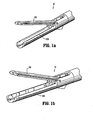
- FIGs 1a and 1b show a clamping device 10 of a linear cutting and stapling device according to an example embodiment of the present invention.
- the clamping device 10 includes an anvil 100 as a first jaw or clamping member, and a cartridge housing 200 as a second jaw clamping member.
- the anvil 100 and the cartridge housing 200 are in an open state.
- the anvil 100 and cartridge housing 200 are rotatable about each other to close from the open state to a closed state where the anvil 100 and cartridge housing 200 are parallel, or substantially parallel, to maintain a tissue gap therebetween that allows for satisfactory staple formation between the cartridge housing 200 and the anvil 100.
- clamping device 10 is symmetric, or substantially symmetric, about a plane extending through an axial centerline of the clamping device 10.
- some features may be described with respect to one side of the clamping device, it should be understood than analogous features are disposed on the opposite side of the clamping device.
- the clamping device 10 is symmetric, or substantially symmetric, other example embodiments may not be.
- FIG 2 is an exploded view of the clamping device 10 of Figures 1a and 1b .
- the clamping device 10 includes a guide screw or member 20, an inner shaft 30, a clamp screw 40, a firing shaft 50, a bevel gear shaft 60, a proximal housing 70, and screws 80.
- the guide member 20 is coupled to the proximal housing 70 and rotatably receives the clamp screw 40.
- Figures 5a and 5b Figure 5a is a cross section taken through a plane crossing the mid- or centerline of the clamping device 10, while the cross-sectional view of Figure 5b is taken through a plane that is slightly offset from the centerline of the clamping device 10
- the guide member 20 has a flange 21 that contacts the staple cartridge housing 200 to prevent the flange from moving axially in a distal direction.
- a proximal face of the flange 21 contacts the proximal housing to restrain the guide member from moving proximally.
- the clamp screw 40 has a head or proximal portion 41 configured to receive a driver to axially rotate the clamp screw 40.
- the clamp screw 40 also has an externally threaded shaft 42 that engages corresponding internal threads of the inner shaft 30.
- axial rotation of the clamp screw 40 in a first direction causes the external threads to rotate within the inner shaft 30 to cause the inner shaft 30 to move in a proximal direction.
- this proximal movement is translated into a clamping force applied between the anvil 100 and the cartridge housing 200.
- a thrust bearing 22 is provided to transmit the axial force between the clamp screw 40 and the guide member 20 about the guide member 20.
- Rotation of the clamp screw 40 in a second, opposite direction causes the inner shaft 30 to move distally, causing the anvil 100 to rotate away from the cartridge housing.
- a distal end portion of the clamp screw 40 is received in a bore 202 of the cartridge housing 200 to constrain the distal end of the clamp screw 40 during clamping.
- the clamping device 10 To drive a cutting and stapling function, the clamping device 10 includes a firing shaft 50 and a bevel gear shaft 60.
- the bevel gear shaft 60 is coupled to the firing shaft 50 such that rotation of the bevel gear shaft causes rotation of the firing shaft 50. This rotation of the firing shaft is then used to drive a cutting and staple-pushing element in a distal direction to cut and staple clamped tissue.
- the staples are driven from a staple cartridge received by the cartridge housing 200.
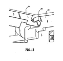
- FIG. 5b and Figure 13 which is a cross sectional view taken through an interface 300 between the anvil 100 and the cartridge housing 200
- the anvil 100 is rotatably coupled to the cartridge housing 200 at the interface 300.
- the interface 300 is formed between a concave surface 210 of the cartridge housing 200 and a convex surface 110 of the anvil 100.
- the concave surface 210 of the cartridge housing 200 is shown, e.g., in Figures 10 to 12
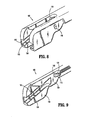
- the convex surface 110 of the anvil 100 is shown, e.g., in Figures 6 to 9 .
- the convex surface 110 of the anvil 100 corresponds to the profile of a raised portion or protrusion 115 that extends or projects away from a lateral surface or face 120 to a raised surface or face 125.
- the protrusion 115 extends inwardly (i.e., in a direction toward an axial centerline of the anvil 100) from an inwardly facing surface 120 (i.e., a surface facing laterally toward the centerline of the anvil 100), it should be understood that the protrusion 115 may extend away from an outwardly facing surface and/or the protrusion 115 may extend between two opposed surfaces.
- the concave surface 210 of the cartridge housing 200 corresponds to the profile of an undercut or inset into a lateral surface or face 220.
- the inset is formed to extend inwardly from an outwardly facing surface 220, it should be understood that the inset may be formed to extend outwardly into an inwardly facing surface and/or the inset may extend through the material to an opposite face or surface.
- the concave surface 210 is formed at a step between the face 220 and an inset surface or face 225.
- the surface 225 is formed on the lateral side of a support member or rib 230.
- the rib 230 separates the concave surface 210 and the inset from a symmetrically formed, or substantially symmetrically formed, second concave surface and second inset.
- This second structure is formed as "mirror image" such that the structure is symmetric about a plane that intersects the axial centerline of the cartridge housing 200 and corresponds to a plane in which the anvil 100 is rotatable with respect to the cartridge housing 200 when the anvil 100 is mated to the cartridge housing 200 at the interface 300.
- the support member 230 may be dispensed with, such that, e.g., the concave surface 210 extends laterally across the cartridge housing 200 to form a single surface 210.
- the support member 230 may be advantageous, however, in that it may help prevent deformation of the cartridge housing 200 due to high forces being exerted at the interface 300.
- the convex surface 110 is slidably coupled with the concave surface 210.
- the contact surface between the convex surface 110 forms an arc with a center corresponding to an axis of rotation between the anvil 100 and the cartridge housing 200.
- the radius of curvature of the concave surface 210 and the convex surface 110 are the same, or substantially the same. This may ensure accurate positioning of anvil 100 with respect to the cartridge housing 200, as well as providing a constant, or substantially constant, axis of rotation between the anvil 100 and the cartridge housing 200 during clamping.
- the interface 300 provides a sliding interface
- a rolling interface may be provided.
- the concave surface 210 may have a larger radius of curvature than the convex surface 110. where, e.g., such a rolling arrangement is provided, the concave surface 210 and the convex surface 110 may be provided with mating teeth, e.g., gear teeth, which may be formed with the respective anvil 100 and cartridge housing 200 monolithically.
- clamping device 10 has two mating interfaces 300 it should be understood that the clamping device 10 may have multiple mating interfaces 300 and that one of the anvil 100 and the cartridge housing 200 may have a combination of convex and concave geometries that mate with a corresponding combination of concave and convex geometries on the other of the anvil 100 and the cartridge housing 200.
- the anvil 100 is constrained axially with respect to the cartridge housing 200 when the convex surface 110 is pressed into the concave surface, e.g., during clamping.
- the contact or interface surface 300 extends from a point proximal to the rotation axis, or center of curvature of the arc of interface 300 (which corresponds to the center of curvature of the convex surface 110 and the center of curvature of the concave surface 210) to a point proximal to the center of the arc of curvature of the interface 300.
- the surface 210 of the cartridge housing 200 is able to exert forces (normal to the surface 210) that have proximally directed components and distally directed components, thereby accurately maintaining the axial position of the anvil 100 with respect to the cartridge housing 200.
- the interface 300 includes a single contact or interface surface, the interface may be provided with multiple and/or intermittent contact or interface surfaces.
- the surface 110 When the convex surface 110 is not pressed into the concave surface 210, e.g., when no clamping force is applied to the anvil 100, the surface 110 may separate from the surface 210, in which case the anvil 100 may be moved axially with respect to the cartridge housing 200 such that the surface 110 clears the surface 210. In this manner, the anvil 100 may be removed, or decoupled, from the cartridge housing 200.
- the position of the anvil 100 is maintained by one or more secondary positioning members 80.
- the secondary positioning members 80 of the device 10 are shown as, e.g., screws.
- Each secondary positioning member 80 is supported by the cartridge housing 200 and extends into a secondary positioning slot 140 in the anvil 100.
- the secondary positioning slot 140 has an arced geometry, the center of curvature of the arc located at the axis of rotation of the anvil 100 with respect to the cartridge housing when the surfaces 110 and 210 are mated.
- the extension of the secondary positioning member into the secondary positioning slot 140 does not interfere with the rotational motion of the anvil 100 with respect to the cartridge housing 200 when the anvil 100 is moved between an open position and a closed position.
- the length and/or positioning of the arced slot may be selected, however, to limit the range of rotation of the anvil 100 when rotated about the cartridge housing. This limiting would be provided due to contact or interference between the secondary positioning member 80 and one or both of the ends of the arced secondary positioning slot 140.
- the secondary positioning member 80 is a screw having external threads that engage internal threads of a secondary positioning aperture 240 of the cartridge housing 200.
- the secondary positioning member 80 is a screw, it should be appreciated that the secondary positioning member 80 may be any appropriate structure, e.g., a pin.
- the slot 140 is a blind slot (i.e., the depth of the slot does not extend entirely through the structure of the anvil 100), a through slot may be provided. A blind slot may be advantageous, however, due to the added rigidity provided by the material at the bottom of the slot.
- the secondary positioning member 80 may be supported in either of the anvil 100 and the cartridge housing 200.
- two secondary positioning members 80 are shown, more than two secondary positioning members 80 may be provided, or a single secondary positioning member 80 may be provided.
- a single pin or screw could extend through both slots 140.
- the inner shaft 30 moves proximally and distally within a slot 205 of the cartridge housing 200.
- the slot 205 constrains the inner shaft 30 to an axial path with respect to the cartridge housing 200.
- the inner shaft 30 may move distally and proximally along this path, but is limited with regard to movement in other directions in the plane of rotation of the anvil 100 about the cartridge housing 200. It should be appreciated that the path of the inner shaft 30 provided by the slot 205 need not necessarily be linear.
- the cartridge housing 200 may also rotationally constrain the inner shaft 30 about the axis of the clamp screw 40 with respect to the cartridge housing 200 such that rotation of the clamp screw 40 with respect to the cartridge housing 200 does not cause rotation of the inner shaft 30 about the cartridge housing 200.
- clamp screw 40 rotates relative to the cartridge housing 200 and the inner shaft 30, the threaded engagement between the clamp screw 40 and the inner shaft 30 causing the inner shaft 30 to translate distally or proximally depending on the direction of rotation of the clamp screw 40.
- the inner shaft 30 extends laterally outwardly into actuation slots 105 of the anvil 100, such that the distal or proximal translation of the inner shaft 30 within the slot 205 of the cartridge housing 200 causes the shaft to translate, e.g., slide, along the paths of the actuation slots 105. It should be appreciated that the inner shaft 30 may be configured to roll along the slots 105 of the anvil 100 and/or along the slot 205 of the cartridge housing 200.
- Each slot 105 is located and oriented such that the movement of the inner shaft 30 along the slot 205 of the cartridge housing 200 and along the actuation slot 105 of the anvil 100 causes the anvil 100 to rotate with respect to cartridge housing 200. This is accomplished by providing the slots 105 and 205 such that the distal portions of the slots 105 and 205 align when the anvil 100 is in the open position with respect to the cartridge housing 200 and the proximal portions of the slots 105 and 205 align when the anvil 100 is in a closed position with respect to the cartridge housing 200.
- the inner shaft 30 serves to align the slots 105 and 205 at the position along the slots 105 and 205 at which the inner shaft 30 is located.
- the alignment location of the slots 105 and 205 moves proximally, thereby moving the anvil 100 toward the closed position with respect to the cartridge housing 200, and vice-versa when the clamp screw 40 is rotated in the opposite direction.
- the interaction between the inner shaft 30 and the slots 105 and 205 acts to press the proximal portions of the anvil 100 and the cartridge housing 200 away from each other.
- the interface 300 between the convex surface 110 of the anvil 100 and the concave surface 210 of the cartridge housing 200 acts a fulcrum such that the distal clamping portions of the anvil 100 and the cartridge housing 200 are urged together.
- the slots of the example clamping device 10 are positioned proximal to the axis of rotation of the anvil 100 with respect to the cartridge housing 200, it should be appreciated that the slots 105 and 205 may be position distal to the axis of rotation. In this situation, the interaction between the inner shaft and the slots would act to pull the anvil 100 toward the cartridge housing 200 at a location between the axis of rotation and the distal clamping portions of the anvil 100 and the cartridge housing 200.
- the proximal ends of the actuation slots 105 of the anvil 100 are open. This allows the anvil 100 to be coupled and decoupled to and from the cartridge housing 200 in a simple and expeditious manner.
- the open ends of the actuation slots 105 are aligned to receive the lateral extensions of the inner shaft 30.
- the anvil 100 is moved proximally so that the slots receive and slide along the axial extensions of the inner shaft 30 until the convex surface 110 of the anvil 100 is positioned below the concave surface 210 of the cartridge housing 200.
- the secondary positioning members 80 may then be inserted to extend into the secondary positioning slots 140.
- the secondary positioning members 80 may be retracted and/or removed.
- the anvil 100 may then be pulled distally, allowing the convex surface 110 to clear the concave surface 210, until the lateral extensions of the inner shaft 30 exit the open proximal ends of the actuation slots 105.
- the proximal portion of the anvil 100 has two parallel, or substantially parallel, extensions or wings 150 into which the slots 205 are formed.
- the extensions 150 are separated by a medial space 160 that extends distally to a point beyond the convex surfaces 110.
- the protrusions 115 (along with convex surfaces 110) and the actuation slots 105 are formed or disposed on the medial or inner sides or faces of the extensions 150, while the secondary positioning slots 140 are formed or disposed on the outer sides or faces of the extensions 150.
- the strength of the extensions 150 benefits from the presence of outer structure 151 adjacent to the blind slots 105, as opposed to through slots that would not have this structure 151.
- the strengthening due to this structure 151 may reduce the possibility of deflection and/or deformation of the extensions 150 under high clamping loads.
- the extensions 150 are received in a pair of channels 260 of the cartridge housing 200, as shown, e.g., in Figure 14 .
- the channels 260 separate a middle extension 270 and two outer extensions 280.
- the middle extension 270 includes the slot 205, and the concave surfaces 210, while the outer extensions 280 include the secondary positioning apertures 240.
- the middle extension 270 also includes first and second axial apertures 290 and 291, which extend axially, referring to Figure 5a , through the middle extension 270 to corresponding proximal openings in the middle extension 270.
- the first axial aperture 290 allows the firing shaft 50, which is housed in an enclosed channel or bore 292 of the middle extension 270, to access and drive a cutting and staple-driving element in the distal portion of the cartridge housing 200.
- the second aperture 291 provides access to an enclosed channel or bore 293 between the distal and proximal ends of the middle extension 270.
- the channel 293 may be used for any appropriate purpose, including, e.g., providing a housing for wiring, which may be used, e.g., to communicate information related to staple cartridges that may be housed in the cartridge housing 200. The information may be, e.g., stored on a chip of the staple cartridge.
- the distal portion of the cartridge housing 200 which functions as a lower clamping jaw, includes a channel 275 configured to receive the staple cartridge.
- the lateral confinement, captivation or constraint of the extensions 160 of the anvil 100 may serve to prevent or reduce the likelihood of lateral deflection and/or deformation of the extensions 160, e.g., under high clamping forces.
- the structure of the extensions 270 and 280 of the cartridge housing 200 may prevent or reduce the likelihood of deflection and/or deformation of the cartridge housing 200.
- the extensions 270 and 280 extend in the plane of the clamping rotation of the anvil with respect to the cartridge housing. This may provide added strength in the plane of the clamping rotation of the anvil 100 with respect to the cartridge housing 200.
- the presence of substantial structure due to the outer extensions 280 at a distance (e.g., along the lateral circumference of the cartridge housing 200) from the axial centerline of the cartridge housing 200 may provide increased torsional rigidity to further resist deflection of the cartridge housing 200.
- the cartridge housing 200 includes lateral supports or ribs 271, 272 that extend between the middle extension 270 and the outer extensions 280.
- the lateral supports 271, 272 are spaced and dimensioned to avoid interfering with the rotation of the wings or extensions 150 of the anvil 100 when the anvil 100 is rotated during clamping and opening procedures.
- FIG 15 illustrates an alternative clamping device 1000.
- the device 1000 includes a first jaw or anvil 1100 and a second jaw or staple cartridge housing 1200.
- the staple cartridge housing 1200 is shown with a staple cartridge 1600, which is of a type also insertable into the staple cartridge housing 200 described above.
- the anvil 1100 is rotatable with respect to the cartridge housing 1200 about a pin inserted through a bore 1103 of the anvil 1100 and a corresponding bore of the cartridge housing 1200.
- the anvil 1100 is actuatable between an open state and a closed state via actuation of a shaft 1030 along a slot 1205 of the cartridge housing 1200 and a pair of slots 1105 of the anvil.
- the slots 1105 are formed in two respective wings or extensions 1150 of the anvil 1100. As opposed to the slots 105 disposed in the extensions 150 of the anvil 100, the slots 1105 are through-slots, extending entirely through the structure of each respective extension 1150. Thus, under high clamping forces applied between the anvil 1100 and the cartridge housing 1200, the extensions 1150 may be more likely to deflect and/or deform. Moreover, the bore 1103, which forms a through hole in the anvil 1100, may further reduce the clamping forces that may be applied without deflection or deformation in the anvil 1100 and/or the cartridge housing 1200, as opposed to the interface 300 of the clamping device 10.
- the clamping device 1000 does not include any structure disposed laterally (along the axis of rotation) outside of the extensions 1150.
- the extensions 1150 have less constraint against laterally outward deflection, as compared to the clamping device 10, where the outer extensions 280 of the cartridge housing 200 extend along laterally outward sides of the extensions 150 of the anvil 100 to generally laterally confine in a particular arrangement the extensions 150.
- the cartridge housing 1200 may be more susceptible to deflection, as opposed to the cartridge housing 200, which has the additional structural support provided by the two outer extensions 280.
- the clamping device 1000 it is noted that the stresses due to the clamping forces exerted between the distal portions of the anvil 1100 and the cartridge housing 1200 are concentrated in the interface between the distal or jaw portion and the single extension 1208.
- the interface between the distal or jaw portion of the cartridge housing 200 is spread among the two outer extensions 280 and the middle extension 270. This may allow greater clamping forces to be applied without unacceptable deflection or fatigue failure at the junction between the distal jaw portion and the proximal portion of the cartridge housing 200.
- FIG 16 shows a surgical instrument 5 including the clamping device 10.
- the clamping device 10 is coupled to a shaft housing 11, that contains a first drive shaft configured to drive clamp screw 40 and a second drive shaft configured to drive bevel gear shaft 60.
- a handle portion 12 At a proximal end of the shaft housing 11 is a handle portion 12 that includes user controls and at least one actuator configured to rotate the first and second drive shafts based on the user controls.
- the drive shafts are independently rotatable so that the clamping (or opening) of the jaws may be controlled independently from the driving of the cutter/staple pusher.
- the instrument contains many features that are analogous to the instruments described in U.S. Patent Application Publication No. 2009/0101692 , which is expressly incorporated herein in its entirely by reference thereto.
- the example instrument 5 is a hand-held, self-contained, battery-powered unit, it should be appreciated that the clamping device 10 may be provided with any appropriate instrument, e.g., a console-based surgical instrument
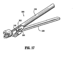
- FIGS 17 and 18 show a clamping device 2000.
- the clamping device 2000 includes the features of the clamping devices described above, but differs in that the anvil 2100 includes through slots 2105 rather than blind slots 105. This arrangement may be suitable to simplify the manufacturing of the slots.
- the clamping device is not assembled in exactly the same manner as described above with regard to clamping device 10. This is because the closed distal end of the through slots 2105 prevent the anvil 2100 from being proximally slid onto the inner shaft 2030.
- the anvil 2100 is rotatably coupled to the housing 2200 prior to placement of the inner shaft 2030.
- the through slot 2105 of the anvil 2100 is aligned with a hole or aperture 2400 in the side of the housing 2200.
- the inner shaft 2030 may be inserted through the hole 2400 until the inner shaft 2030 engages both through slots 2105.
- the clamp screw 2040 may then by inserted to engage the inner threads of the inner shaft 2030.
- a plug 2500 is provided, which closes the hole after the inner shaft 2030 has been inserted therethrough.
- the clamping device 2000 has a single hole with a single plug, it should be understood that two or more holes and/or two or more plugs may be provided. However, it may be suitable to minimized the number of holes to limit the possibility of contamination, simplify the manufacturing process, and/or reduce any possibility of compromising the strength of the housing 2200.
- the through slots 2105 are shown as enclosed, it should be understood that the through slots 2105 may have a forked structure, such that one end of one or more of the slots 2105, e.g., a proximal end, is open.
Landscapes
- Health & Medical Sciences (AREA)
- Life Sciences & Earth Sciences (AREA)
- Surgery (AREA)
- Heart & Thoracic Surgery (AREA)
- Engineering & Computer Science (AREA)
- Biomedical Technology (AREA)
- Nuclear Medicine, Radiotherapy & Molecular Imaging (AREA)
- Medical Informatics (AREA)
- Molecular Biology (AREA)
- Animal Behavior & Ethology (AREA)
- General Health & Medical Sciences (AREA)
- Public Health (AREA)
- Veterinary Medicine (AREA)
- Surgical Instruments (AREA)
Abstract
Description
- The present invention relates generally to a surgical clamping device.
- Some surgical procedures require the compression, e.g., clamping, of a patient's tissue. Such procedures may include, e.g., anastomosing, stapling, and resecting of tissue. For example, where cancerous tissue is identified in a patient's gastrointestinal tract, the cancerous tissue may need to be surgically removed. Where, for example, the cancerous tissue is located on the colon and is accessible by surgical instrumentation, the surgeon may make an incision in the patient's abdomen to allow access to the bowel. The surgeon may then use a linear cutting and stapling device, such as that described in
U.S. Patent Application Publication No. 2009/0101692 , which is expressly incorporated herein in its entirety by reference thereto, to cut and staple the colon tissue on opposite sides of the cancerous portion to be removed. In this procedure, the colon is externally clamped (e.g., between opposed jaws) to compress the tissue. While the tissue is compressed, a cutter and a stapler are activated to make a linear cut and apply typically two linear rows of staples in the areas adjacent the cut. - The stapling thus closes both open ends of the portion of the bowel to be removed, as well as providing a temporary closure of the two cut ends of the bowel. This closure limits exposure of the surrounding tissue to the interior of the bowel, thus limiting the risk of infection.
- After the cutting and stapling procedure, the cancerous portion of tissue may be removed from the patient's body.
- To achieve effective stapling, e.g., in the above procedures, the tissue must be compressed to the extent that there is an adequately small tissue gap, e.g., one millimeter, between the faces of the tool. During this compression, the mechanical components of the clamping mechanism of the cutting and stapling device may be subjected to a high level of force or strain. where, e.g., the jaws are closed by rotation of one or both of the jaws about a proximally located pin, the pin and/or the adjacent structures of the jaws in communication with the pin bear a substantial load, which may lead to deformation. Where the pin passes through a through hole in one or both of the jaws, deformation may be more likely due to the weakening of the jaw structure resulting from the through holes.
- Further, proximally extending structures of the jaws, e.g., an anvil, may deform, including, e.g., splaying laterally outwardly. The likelihood of deformation may also be increased by the removal of material for through slots, e.g., in a pin-and-slot type actuation arrangement.
- This deformation may lead to, e.g., misalignment between the jaws and/or failure of the clamping mechanism. Where one of the jaws is configured as an anvil and the other jaw is configured to drive staples, e.g., from a staple cartridge, into the anvil, misalignment of the jaws may cause misalignment of the anvil and staple pockets. This may cause the staples to be improperly formed, which may increase the risk of sepsis and other potentially dangerous complications.
- Thus, it is desirable to provide a clamping mechanism that substantially reduces the likelihood of deformation in the jaws.
- Example embodiments of the present invention provide a high-strength anvil and housing while maintaining accurate anvil to staple pocket positioning. This may be accomplished by integrating the pivot point into the anvil and housing geometry rather than using a separate pivot pin. This design may be advantageous in that the integrity of the anvil and housing is not compromised by the need to drill a through.hole for a pin. In this regard, a portion of material (which would otherwise be removed due to drilling of a through hole) remains in the region of the pivot point to assist in supporting the significant loads exerted during the compression of tissue. This may result in increased clamping force with less deflection in the anvil and/or the housing.
- Accurate distal to proximal anvil positioning may be accomplished by providing the anvil and cartridge housing with mating geometry, e.g., mating cylindrical surfaces. For example, the anvil or the cartridge housing may have a concave cylindrical surface that receives a convex cylindrical surface (which may have the same, or substantially the same, radius of curvature) of the other of the anvil or the cartridge housing. It should be understood that the device may have multiple mating interfaces and that one of the anvil and the cartridge housing may have a combination of convex and concave geometries that mate with a corresponding combination of concave and convex geometries on the other of the anvil and the cartridge housing.
- When the mating surfaces of the anvil and the cartridge housing are mated and clamping force is exerted between the anvil and the cartridge housing, the mated surfaces of the anvil and the cartridge housing accurately locate, or position, the anvil. In this regard, the example device is configured such that applying a load to the anvil during clamping causes the mating surfaces to be pressed toward each other, thereby maintaining the mated arrangement. In the absence of a load being applied to the anvil, or when the mated surfaces are not being pressed together, the position of the anvil is maintained by a secondary positioning member, e.g., a secondary pin or screw, which may, e.g., be supported by the housing and received by the anvil, e.g., in a slot of a wing of the anvil. Where the secondary positioning member is received in a slot, the slot may be a blind slot as opposed to a through slot, to avoid potential weakening of the structure. It should be appreciated that the secondary positioning member may be supported in either of the anvil and the cartridge housing. Further, a plurality of secondary positioning members may be provided such that either or both of the anvil and the cartridge housing support the positioning members.
- According to an example embodiment, the anvil and cartridge housing are configured so that the anvil is generally laterally confined in a particular arrangement by the cartridge housing. This is accomplished by one or more structures of the anvil being receivable in a slot or space formed in the cartridge housing. For example, two wings of the anvil may be received in two corresponding slots of the cartridge housing. This slot configuration allows the presence of the cartridge housing structure around a relatively high portion of the circumference of the cartridge housing, which may be advantageous with regard to the strength of the cartridge housing.
- The slotted arrangement may also be advantageous with regard to the anvil, since the structure of the cartridge housing extends on laterally outward sides of the wings and between the wings when the anvil is mated to the cartridge housing. This may, e.g., decrease the likelihood of lateral deflection of the wings.
- The anvil of the example embodiment also has a cam slot for actuation of the anvil that does not extend laterally through the anvil. This blind slot may increase the strength of the anvil due to the presence of more structure on the outer surface as opposed to a through slot.
- According to an example embodiment of the present invention, a device for clamping tissue includes a first jaw having a distal portion for communicating with tissue and a proximal portion having a first wing and a second wing. The device also includes a second jaw having a distal portion for communicating with tissue and a proximal portion having a first slot and a second slot, the first slot disposed between a middle structure and a first lateral structure, the second slot disposed between the middle structure and a second lateral structure. The first jaw is rotatably coupleable to the second jaw with the first wing extending into the first slot and the second wing extending into the second slot.
- The first wing may include a first blind slot and the second wing may include a second blind slot, the first and second blind slots configured to receive opposite ends of an actuation shaft.
- The middle structure of the second jaw may include a slot configured to receive a middle portion of the actuation shaft when the ends of the actuation shaft are received in the blind slots of the first and second wings.
- The first jaw may include a first bearing surface formed monolithically with the first jaw and the second jaw may include a second bearing surface formed monolithically with the second jaw, the first bearing surface communicating with the second bearing surface to define an axis of rotation between the first jaw and the second jaw when the first jaw is rotatably coupled to the second jaw.
- The first and second bearing surfaces may have curvatures that maintain an axial position of the first jaw with respect to the second jaw when a clamping force is applied between the first jaw and the second jaw.
- The device may also include a secondary positioning member coupled to one of the first jaw and the second jaw and configured to prevent removal of the first jaw from the second jaw and to allow rotation of the first jaw with respect to the second jaw.
- The secondary positioning member may be at least one of a pin and a screw.
- The secondary positioning member may be configured to extend from the one of the first jaw and the second jaw into a curved slot of the other one of the first jaw and the second jaw.
- The curved slot may be a blind slot.
- The first jaw may be an anvil and the second jaw may be a staple cartridge housing configured to drive staples into the anvil when the anvil is in a closed position.
- According to an example embodiment of the present invention, a device for clamping tissue includes a first jaw having a first jaw body having a proximal portion and a distal clamping portion, and a first bearing surface formed monolithically with the first jaw body as a single piece. The device also includes a second jaw having a second jaw body having a proximal portion and a distal clamping portion, and a second bearing surface formed monolithically with the second jaw body. The second jaw is rotatably coupleable to the first jaw such that the first bearing surface communicates with the second bearing surface at an interface. The device also includes a driver configured to rotate the first jaw with respect to the second jaw with the interface acting as a fulcrum and defining an axis of rotation between the first jaw and the second jaw.
- The first bearing surface and the second bearing surface may be configured to slide with respect to each other along the interface when the driver rotates the first jaw with respect to the second jaw.
- The interface may extend along a circular arc, the first jaw rotatable with respect to the second jaw about an axis of rotation corresponding to the circle center of the circular arc.
- The first bearing surface may be formed in the first jaw without extending entirely through the first jaw and the second bearing surface may be formed in the second jaw without extending entirely through the second jaw.
- The first jaw may include a first wing and a second wing, the first wing including a first blind slot and the second wing including a second blind slot.
- The driver may include a shaft configured to extend into each of the first blind slot and the second blind slot.
- The shaft may be actuatable along a slot in the second jaw to rotate the first jaw with respect to the second jaw.
- The shaft may be disposed proximally with respect to the interface between the first bearing surface and the second bearing surface.
- The first jaw may be axially insertable and removable from the second jaw when no clamping force is applied between the first jaw and the second jaw.
- The device may further include a secondary positioning member coupled to one of the first jaw and the second jaw and configured to prevent axial removal of the first jaw from the second jaw and to permit rotation of the first jaw with respect to the second jaw.
- The secondary positioning member may be configured to limit the range of rotation between the first jaw and the second jaw to a predetermined angular range.
- The secondary positioning member may be configured to extend from the one of the first jaw and the second jaw into a curved slot of the other one of the first jaw and the second jaw.
- The curved slot may be a blind slot.
- Further details and aspects of example embodiments of the present invention are described in more detail below with reference to the appended figures.
-
-
Figures 1a and 1b show a clamping device according to an example embodiment of the present invention. -
Figure 2 is an exploded view of the clamping device. -
Figure 3 shows components of the clamping device. -
Figure 4 shows components of the clamping device. -
Figures 5a to 5c show cross-sectional views of a proximal portion of the clamping device. -
Figure 6 shows an anvil jaw of the clamping device. -
Figure 7 shows a cross-sectional view of the anvil jaw ofFigure 6 . -
Figure 8 shows a proximal portion of the anvil jaw ofFigure 6 . -
Figure 9 shows a cross-sectional view of the proximal portion shown inFigure 8 . -
Figure 10 shows a staple cartridge housing or jaw of the jaw portion ofFigures 1a and 1b . -
Figure 11 shows a proximal portion of the jaw ofFigure 10 . -
Figure 12 shows a cross-sectional view of the proximal portion ofFigure 11 . -
Figure 13 shows a cross-sectional view of an interface between the anvil ofFigure 6 and the staple cartridge housing ofFigure 10 . -
Figure 14 shows a proximal portion of the clamping device. -
Figure 15 shows an alternative clamping device. -
Figure 16 shows a surgical instrument having the clamping device ofFigures 1 to 14 . -
Figure 17 shows a clamping device according to an example embodiment of the present invention. -
Figure 18 is an exploded view of the clamping device ofFigure 17 . -
Figures 1a and 1b show aclamping device 10 of a linear cutting and stapling device according to an example embodiment of the present invention. The clampingdevice 10 includes ananvil 100 as a first jaw or clamping member, and acartridge housing 200 as a second jaw clamping member. As shown inFigures 1a and 1b , theanvil 100 and thecartridge housing 200 are in an open state. Theanvil 100 andcartridge housing 200 are rotatable about each other to close from the open state to a closed state where theanvil 100 andcartridge housing 200 are parallel, or substantially parallel, to maintain a tissue gap therebetween that allows for satisfactory staple formation between thecartridge housing 200 and theanvil 100. - It is noted that the
clamping device 10 is symmetric, or substantially symmetric, about a plane extending through an axial centerline of theclamping device 10. Thus, although some features may be described with respect to one side of the clamping device, it should be understood than analogous features are disposed on the opposite side of the clamping device. It should be further understood that, although theclamping device 10 is symmetric, or substantially symmetric, other example embodiments may not be. -
Figure 2 is an exploded view of theclamping device 10 ofFigures 1a and 1b . The clampingdevice 10 includes a guide screw ormember 20, aninner shaft 30, aclamp screw 40, a firingshaft 50, abevel gear shaft 60, aproximal housing 70, and screws 80. - Referring to
Figures 3 and 4 , theguide member 20 is coupled to theproximal housing 70 and rotatably receives theclamp screw 40. Further referring toFigures 5a and 5b (Figure 5a is a cross section taken through a plane crossing the mid- or centerline of theclamping device 10, while the cross-sectional view ofFigure 5b is taken through a plane that is slightly offset from the centerline of the clamping device 10), theguide member 20 has aflange 21 that contacts thestaple cartridge housing 200 to prevent the flange from moving axially in a distal direction. A proximal face of theflange 21 contacts the proximal housing to restrain the guide member from moving proximally. - The
clamp screw 40 has a head orproximal portion 41 configured to receive a driver to axially rotate theclamp screw 40. Theclamp screw 40 also has an externally threadedshaft 42 that engages corresponding internal threads of theinner shaft 30. In this regard, axial rotation of theclamp screw 40 in a first direction causes the external threads to rotate within theinner shaft 30 to cause theinner shaft 30 to move in a proximal direction. As set forth in greater detail below, this proximal movement is translated into a clamping force applied between theanvil 100 and thecartridge housing 200. To facilitate rotation of theclamp screw 40 during the clamping, athrust bearing 22 is provided to transmit the axial force between theclamp screw 40 and theguide member 20 about theguide member 20. Rotation of theclamp screw 40 in a second, opposite direction causes theinner shaft 30 to move distally, causing theanvil 100 to rotate away from the cartridge housing. A distal end portion of theclamp screw 40 is received in abore 202 of thecartridge housing 200 to constrain the distal end of theclamp screw 40 during clamping. - To drive a cutting and stapling function, the clamping
device 10 includes a firingshaft 50 and abevel gear shaft 60. Thebevel gear shaft 60 is coupled to the firingshaft 50 such that rotation of the bevel gear shaft causes rotation of the firingshaft 50. This rotation of the firing shaft is then used to drive a cutting and staple-pushing element in a distal direction to cut and staple clamped tissue. The staples are driven from a staple cartridge received by thecartridge housing 200. - Referring to
Figure 5b andFigure 13 , which is a cross sectional view taken through aninterface 300 between theanvil 100 and thecartridge housing 200, theanvil 100 is rotatably coupled to thecartridge housing 200 at theinterface 300. Theinterface 300 is formed between aconcave surface 210 of thecartridge housing 200 and aconvex surface 110 of theanvil 100. Theconcave surface 210 of thecartridge housing 200 is shown, e.g., inFigures 10 to 12 , and theconvex surface 110 of theanvil 100 is shown, e.g., inFigures 6 to 9 . - The
convex surface 110 of theanvil 100 corresponds to the profile of a raised portion orprotrusion 115 that extends or projects away from a lateral surface or face 120 to a raised surface orface 125. Although theprotrusion 115 extends inwardly (i.e., in a direction toward an axial centerline of the anvil 100) from an inwardly facing surface 120 (i.e., a surface facing laterally toward the centerline of the anvil 100), it should be understood that theprotrusion 115 may extend away from an outwardly facing surface and/or theprotrusion 115 may extend between two opposed surfaces. - The
concave surface 210 of thecartridge housing 200 corresponds to the profile of an undercut or inset into a lateral surface orface 220. Although the inset is formed to extend inwardly from an outwardly facingsurface 220, it should be understood that the inset may be formed to extend outwardly into an inwardly facing surface and/or the inset may extend through the material to an opposite face or surface. - Further, the
concave surface 210 is formed at a step between theface 220 and an inset surface orface 225. Thesurface 225 is formed on the lateral side of a support member orrib 230. In the example embodiment, therib 230 separates theconcave surface 210 and the inset from a symmetrically formed, or substantially symmetrically formed, second concave surface and second inset. This second structure is formed as "mirror image" such that the structure is symmetric about a plane that intersects the axial centerline of thecartridge housing 200 and corresponds to a plane in which theanvil 100 is rotatable with respect to thecartridge housing 200 when theanvil 100 is mated to thecartridge housing 200 at theinterface 300. It should be appreciated, however, that thesupport member 230 may be dispensed with, such that, e.g., theconcave surface 210 extends laterally across thecartridge housing 200 to form asingle surface 210. Thesupport member 230 may be advantageous, however, in that it may help prevent deformation of thecartridge housing 200 due to high forces being exerted at theinterface 300. - When the
anvil 100 and thecartridge housing 200 are mated, theconvex surface 110 is slidably coupled with theconcave surface 210. The contact surface between theconvex surface 110 forms an arc with a center corresponding to an axis of rotation between theanvil 100 and thecartridge housing 200. In this regard, the radius of curvature of theconcave surface 210 and theconvex surface 110 are the same, or substantially the same. This may ensure accurate positioning ofanvil 100 with respect to thecartridge housing 200, as well as providing a constant, or substantially constant, axis of rotation between theanvil 100 and thecartridge housing 200 during clamping. - Although the
interface 300 provides a sliding interface, it should be understood that other configurations may be provided. For example a rolling interface may be provided. For example, theconcave surface 210 may have a larger radius of curvature than theconvex surface 110. where, e.g., such a rolling arrangement is provided, theconcave surface 210 and theconvex surface 110 may be provided with mating teeth, e.g., gear teeth, which may be formed with therespective anvil 100 andcartridge housing 200 monolithically. - Although the
clamping device 10 has twomating interfaces 300 it should be understood that theclamping device 10 may havemultiple mating interfaces 300 and that one of theanvil 100 and thecartridge housing 200 may have a combination of convex and concave geometries that mate with a corresponding combination of concave and convex geometries on the other of theanvil 100 and thecartridge housing 200. - Due to the geometry of the
interface 300, theanvil 100 is constrained axially with respect to thecartridge housing 200 when theconvex surface 110 is pressed into the concave surface, e.g., during clamping. In this regard, the contact orinterface surface 300 extends from a point proximal to the rotation axis, or center of curvature of the arc of interface 300 (which corresponds to the center of curvature of theconvex surface 110 and the center of curvature of the concave surface 210) to a point proximal to the center of the arc of curvature of theinterface 300. Thus, thesurface 210 of thecartridge housing 200 is able to exert forces (normal to the surface 210) that have proximally directed components and distally directed components, thereby accurately maintaining the axial position of theanvil 100 with respect to thecartridge housing 200. - It should be appreciated that, although the
interface 300 includes a single contact or interface surface, the interface may be provided with multiple and/or intermittent contact or interface surfaces. - When the
convex surface 110 is not pressed into theconcave surface 210, e.g., when no clamping force is applied to theanvil 100, thesurface 110 may separate from thesurface 210, in which case theanvil 100 may be moved axially with respect to thecartridge housing 200 such that thesurface 110 clears thesurface 210. In this manner, theanvil 100 may be removed, or decoupled, from thecartridge housing 200. - When it is not desired to remove the
anvil 100 from thecartridge housing 200, in the absence of a load being applied to theanvil 100, or when the matedsurfaces anvil 100 is maintained by one or moresecondary positioning members 80. Thesecondary positioning members 80 of thedevice 10 are shown as, e.g., screws. Eachsecondary positioning member 80 is supported by thecartridge housing 200 and extends into asecondary positioning slot 140 in theanvil 100. Thesecondary positioning slot 140 has an arced geometry, the center of curvature of the arc located at the axis of rotation of theanvil 100 with respect to the cartridge housing when thesurfaces secondary positioning slot 140 does not interfere with the rotational motion of theanvil 100 with respect to thecartridge housing 200 when theanvil 100 is moved between an open position and a closed position. The length and/or positioning of the arced slot may be selected, however, to limit the range of rotation of theanvil 100 when rotated about the cartridge housing. This limiting would be provided due to contact or interference between thesecondary positioning member 80 and one or both of the ends of the arcedsecondary positioning slot 140. - The
secondary positioning member 80 is a screw having external threads that engage internal threads of a secondary positioning aperture 240 of thecartridge housing 200. - Although the
secondary positioning member 80 is a screw, it should be appreciated that thesecondary positioning member 80 may be any appropriate structure, e.g., a pin. Moreover, although theslot 140 is a blind slot (i.e., the depth of the slot does not extend entirely through the structure of the anvil 100), a through slot may be provided. A blind slot may be advantageous, however, due to the added rigidity provided by the material at the bottom of the slot. It should be further appreciated that thesecondary positioning member 80 may be supported in either of theanvil 100 and thecartridge housing 200. Further, although twosecondary positioning members 80 are shown, more than twosecondary positioning members 80 may be provided, or a singlesecondary positioning member 80 may be provided. For example, a single pin or screw could extend through bothslots 140. - Referring to
Figures 5a to 5c , to actuate the rotation of theanvil 100, theinner shaft 30 moves proximally and distally within aslot 205 of thecartridge housing 200. Theslot 205 constrains theinner shaft 30 to an axial path with respect to thecartridge housing 200. Thus, theinner shaft 30 may move distally and proximally along this path, but is limited with regard to movement in other directions in the plane of rotation of theanvil 100 about thecartridge housing 200. It should be appreciated that the path of theinner shaft 30 provided by theslot 205 need not necessarily be linear. Thecartridge housing 200 may also rotationally constrain theinner shaft 30 about the axis of theclamp screw 40 with respect to thecartridge housing 200 such that rotation of theclamp screw 40 with respect to thecartridge housing 200 does not cause rotation of theinner shaft 30 about thecartridge housing 200. Thus, clampscrew 40 rotates relative to thecartridge housing 200 and theinner shaft 30, the threaded engagement between theclamp screw 40 and theinner shaft 30 causing theinner shaft 30 to translate distally or proximally depending on the direction of rotation of theclamp screw 40. - The
inner shaft 30 extends laterally outwardly intoactuation slots 105 of theanvil 100, such that the distal or proximal translation of theinner shaft 30 within theslot 205 of thecartridge housing 200 causes the shaft to translate, e.g., slide, along the paths of theactuation slots 105. It should be appreciated that theinner shaft 30 may be configured to roll along theslots 105 of theanvil 100 and/or along theslot 205 of thecartridge housing 200. - Each
slot 105 is located and oriented such that the movement of theinner shaft 30 along theslot 205 of thecartridge housing 200 and along theactuation slot 105 of theanvil 100 causes theanvil 100 to rotate with respect tocartridge housing 200. This is accomplished by providing theslots slots anvil 100 is in the open position with respect to thecartridge housing 200 and the proximal portions of theslots anvil 100 is in a closed position with respect to thecartridge housing 200. In this regard, theinner shaft 30 serves to align theslots slots inner shaft 30 is located. Thus, when theclamp screw 40 rotates in a first direction to translate theinner shaft 30 in the proximal direction, the alignment location of theslots anvil 100 toward the closed position with respect to thecartridge housing 200, and vice-versa when theclamp screw 40 is rotated in the opposite direction. - During clamping, the interaction between the
inner shaft 30 and theslots anvil 100 and thecartridge housing 200 away from each other. In this regard, theinterface 300 between theconvex surface 110 of theanvil 100 and theconcave surface 210 of thecartridge housing 200 acts a fulcrum such that the distal clamping portions of theanvil 100 and thecartridge housing 200 are urged together. - Although the slots of the
example clamping device 10 are positioned proximal to the axis of rotation of theanvil 100 with respect to thecartridge housing 200, it should be appreciated that theslots anvil 100 toward thecartridge housing 200 at a location between the axis of rotation and the distal clamping portions of theanvil 100 and thecartridge housing 200. - The proximal ends of the
actuation slots 105 of theanvil 100 are open. This allows theanvil 100 to be coupled and decoupled to and from thecartridge housing 200 in a simple and expeditious manner. To couple theanvil 100 to thecartridge housing 200, the open ends of theactuation slots 105 are aligned to receive the lateral extensions of theinner shaft 30. Theanvil 100 is moved proximally so that the slots receive and slide along the axial extensions of theinner shaft 30 until theconvex surface 110 of theanvil 100 is positioned below theconcave surface 210 of thecartridge housing 200. Thesecondary positioning members 80 may then be inserted to extend into thesecondary positioning slots 140. - To remove the
anvil 100, thesecondary positioning members 80 may be retracted and/or removed. Theanvil 100 may then be pulled distally, allowing theconvex surface 110 to clear theconcave surface 210, until the lateral extensions of theinner shaft 30 exit the open proximal ends of theactuation slots 105. - As shown, e.g., in
Figures 6 to 9 , the proximal portion of theanvil 100 has two parallel, or substantially parallel, extensions orwings 150 into which theslots 205 are formed. Theextensions 150 are separated by amedial space 160 that extends distally to a point beyond the convex surfaces 110. The protrusions 115 (along with convex surfaces 110) and theactuation slots 105 are formed or disposed on the medial or inner sides or faces of theextensions 150, while thesecondary positioning slots 140 are formed or disposed on the outer sides or faces of theextensions 150. - The strength of the
extensions 150 benefits from the presence ofouter structure 151 adjacent to theblind slots 105, as opposed to through slots that would not have thisstructure 151. The strengthening due to thisstructure 151 may reduce the possibility of deflection and/or deformation of theextensions 150 under high clamping loads. - When the
anvil 100 is coupled to thecartridge housing 200 as described above, theextensions 150 are received in a pair ofchannels 260 of thecartridge housing 200, as shown, e.g., inFigure 14 . Thus, theextensions 150 of theanvil 100 are generally laterally captivated, confined or constrained in a particular arrangement by thecartridge housing 200. Thechannels 260 separate amiddle extension 270 and twoouter extensions 280. Themiddle extension 270 includes theslot 205, and theconcave surfaces 210, while theouter extensions 280 include the secondary positioning apertures 240. Themiddle extension 270 also includes first and secondaxial apertures Figure 5a , through themiddle extension 270 to corresponding proximal openings in themiddle extension 270. The firstaxial aperture 290 allows the firingshaft 50, which is housed in an enclosed channel or bore 292 of themiddle extension 270, to access and drive a cutting and staple-driving element in the distal portion of thecartridge housing 200. Thesecond aperture 291 provides access to an enclosed channel or bore 293 between the distal and proximal ends of themiddle extension 270. Thechannel 293 may be used for any appropriate purpose, including, e.g., providing a housing for wiring, which may be used, e.g., to communicate information related to staple cartridges that may be housed in thecartridge housing 200. The information may be, e.g., stored on a chip of the staple cartridge. The distal portion of thecartridge housing 200, which functions as a lower clamping jaw, includes achannel 275 configured to receive the staple cartridge. - The lateral confinement, captivation or constraint of the
extensions 160 of theanvil 100 may serve to prevent or reduce the likelihood of lateral deflection and/or deformation of theextensions 160, e.g., under high clamping forces. - Further, the structure of the
extensions cartridge housing 200 may prevent or reduce the likelihood of deflection and/or deformation of thecartridge housing 200. In this regard, theextensions anvil 100 with respect to thecartridge housing 200. Further, the presence of substantial structure due to theouter extensions 280 at a distance (e.g., along the lateral circumference of the cartridge housing 200) from the axial centerline of thecartridge housing 200 may provide increased torsional rigidity to further resist deflection of thecartridge housing 200. - The
cartridge housing 200 includes lateral supports orribs middle extension 270 and theouter extensions 280. The lateral supports 271, 272 are spaced and dimensioned to avoid interfering with the rotation of the wings orextensions 150 of theanvil 100 when theanvil 100 is rotated during clamping and opening procedures. -
Figure 15 illustrates analternative clamping device 1000. Thedevice 1000 includes a first jaw oranvil 1100 and a second jaw orstaple cartridge housing 1200. Thestaple cartridge housing 1200 is shown with astaple cartridge 1600, which is of a type also insertable into thestaple cartridge housing 200 described above. Theanvil 1100 is rotatable with respect to thecartridge housing 1200 about a pin inserted through abore 1103 of theanvil 1100 and a corresponding bore of thecartridge housing 1200. Theanvil 1100 is actuatable between an open state and a closed state via actuation of ashaft 1030 along aslot 1205 of thecartridge housing 1200 and a pair ofslots 1105 of the anvil. - The
slots 1105 are formed in two respective wings orextensions 1150 of theanvil 1100. As opposed to theslots 105 disposed in theextensions 150 of theanvil 100, theslots 1105 are through-slots, extending entirely through the structure of eachrespective extension 1150. Thus, under high clamping forces applied between theanvil 1100 and thecartridge housing 1200, theextensions 1150 may be more likely to deflect and/or deform. Moreover, thebore 1103, which forms a through hole in theanvil 1100, may further reduce the clamping forces that may be applied without deflection or deformation in theanvil 1100 and/or thecartridge housing 1200, as opposed to theinterface 300 of theclamping device 10. - Further, the
clamping device 1000 does not include any structure disposed laterally (along the axis of rotation) outside of theextensions 1150. Thus, under high clamping forces, theextensions 1150 have less constraint against laterally outward deflection, as compared to theclamping device 10, where theouter extensions 280 of thecartridge housing 200 extend along laterally outward sides of theextensions 150 of theanvil 100 to generally laterally confine in a particular arrangement theextensions 150. - Still further, since the only structure of the
cartridge housing 1200 extending along the axial extension of theslot 1205 is a single vertically orientedaxial extension 1208, thecartridge housing 1200 may be more susceptible to deflection, as opposed to thecartridge housing 200, which has the additional structural support provided by the twoouter extensions 280. With regard to theclamping device 1000, it is noted that the stresses due to the clamping forces exerted between the distal portions of theanvil 1100 and thecartridge housing 1200 are concentrated in the interface between the distal or jaw portion and thesingle extension 1208. In contrast, referring to theclamping device 10 illustrated, e.g., inFigures 11 and 12 , the interface between the distal or jaw portion of thecartridge housing 200 is spread among the twoouter extensions 280 and themiddle extension 270. This may allow greater clamping forces to be applied without unacceptable deflection or fatigue failure at the junction between the distal jaw portion and the proximal portion of thecartridge housing 200. -
Figure 16 shows asurgical instrument 5 including theclamping device 10. The clampingdevice 10 is coupled to ashaft housing 11, that contains a first drive shaft configured to driveclamp screw 40 and a second drive shaft configured to drivebevel gear shaft 60. At a proximal end of theshaft housing 11 is ahandle portion 12 that includes user controls and at least one actuator configured to rotate the first and second drive shafts based on the user controls. In this regard, the drive shafts are independently rotatable so that the clamping (or opening) of the jaws may be controlled independently from the driving of the cutter/staple pusher. The instrument contains many features that are analogous to the instruments described inU.S. Patent Application Publication No. 2009/0101692 , which is expressly incorporated herein in its entirely by reference thereto. Although theexample instrument 5 is a hand-held, self-contained, battery-powered unit, it should be appreciated that theclamping device 10 may be provided with any appropriate instrument, e.g., a console-based surgical instrument. -
Figures 17 and18 show aclamping device 2000. Theclamping device 2000 includes the features of the clamping devices described above, but differs in that theanvil 2100 includes throughslots 2105 rather thanblind slots 105. This arrangement may be suitable to simplify the manufacturing of the slots. - Since the through
slots 2105 do not have open proximal ends, such as those ofblind slots 105, the clamping device is not assembled in exactly the same manner as described above with regard to clampingdevice 10. This is because the closed distal end of the throughslots 2105 prevent theanvil 2100 from being proximally slid onto theinner shaft 2030. Thus, theanvil 2100 is rotatably coupled to thehousing 2200 prior to placement of theinner shaft 2030. In this regard, after theanvil 2100 is coupled to thehousing 2200, the throughslot 2105 of theanvil 2100 is aligned with a hole oraperture 2400 in the side of thehousing 2200. At this stage, theinner shaft 2030 may be inserted through thehole 2400 until theinner shaft 2030 engages both throughslots 2105. Theclamp screw 2040 may then by inserted to engage the inner threads of theinner shaft 2030. - To reduce any possibility of contamination, e.g., dirt, entering the mechanism through the
hole 2400, aplug 2500 is provided, which closes the hole after theinner shaft 2030 has been inserted therethrough. Although theclamping device 2000 has a single hole with a single plug, it should be understood that two or more holes and/or two or more plugs may be provided. However, it may be suitable to minimized the number of holes to limit the possibility of contamination, simplify the manufacturing process, and/or reduce any possibility of compromising the strength of thehousing 2200. - Although the through
slots 2105 are shown as enclosed, it should be understood that the throughslots 2105 may have a forked structure, such that one end of one or more of theslots 2105, e.g., a proximal end, is open. - Although the present invention has been described with reference to particular examples and exemplary embodiments, it should be understood that the foregoing description is in no manner limiting. Moreover, the features described herein may be used in any combination.
- The invention may be described by reference to the following numbered paragraphs:
- 1. A device for clamping tissue, comprising: a first jaw including a distal portion adapted to communicate with tissue, and a proximal portion having a first wing and a second wing; and a second jaw including a distal portion adapted to communicate with tissue, and a proximal portion having a first slot and a second slot, the first slot disposed between a middle structure and a first lateral structure, the second slot disposed between the middle structure and a second lateral structure, wherein the first jaw is rotatably coupleable to the second jaw with the first wing extending into the first slot and the second wing extending into the second slot.
- 2. The device of paragraph 1, wherein the first wing includes a first blind slot and the second wing includes a second blind slot, the first and second blind slots configured to receive opposite ends of an actuation shaft.
- 3. The device of paragraph 2, wherein the middle structure of the second jaw includes a slot configured to receive a middle portion of the actuation shaft when the ends of the actuation shaft are received in the blind slots of the first and second wings.
- 4. The device of paragraph 1, wherein the first jaw includes a first bearing surface formed monolithically with the first jaw and the second jaw includes a second bearing surface formed monolithically with the second jaw, the first bearing surface communicating with the second bearing surface to define an axis of rotation between the first jaw and the second jaw when the first jaw is rotatably coupled to the second jaw.
- 5. The device of paragraph 4, wherein the first and second bearing surfaces have curvatures that maintain an axial position of the first jaw with respect to the second jaw when a clamping force is applied between the first jaw and the second jaw.
- 6. The device of paragraph 4, further comprising a secondary positioning member coupled to one of the first jaw and the second jaw and configured to prevent removal of the first jaw from the second jaw and to allow rotation of the first jaw with respect to the second jaw.
- 7. The device of paragraph 6, wherein the secondary positioning member is at least one of a pin and a screw.
- 8. The device of paragraph 6, wherein the secondary positioning member is configured to extend from the one of the first jaw and the second jaw into a curved slot of the other one of the first jaw and the second jaw.
- 9. The device of paragraph 8, wherein the curved slot is a blind slot.
- 10. The device of paragraph 1, wherein the first jaw is an anvil and the second jaw is a staple cartridge housing configured to drive staples into the anvil when the anvil is in a closed position.
- 11. A device for clamping tissue, comprising: a first jaw including a first jaw body having a proximal portion and a distal clamping portion, and a first bearing surface formed monolithically with the first jaw body as a single piece, a second jaw including a second jaw body having a proximal portion and a distal clamping portion, and a second bearing surface formed monolithically with the second jaw body, the second jaw being rotatably coupleable to the first jaw such that the first bearing surface communicates with the second bearing surface at an interface; and a driver configured to rotate the first jaw with respect to the second jaw with the interface acting as a fulcrum and defining an axis of rotation between the first jaw and the second jaw.
- 12. The device of
paragraph 11, wherein the first bearing surface and the second bearing surface are configured to slide with respect to each other along the interface when the driver rotates the first jaw with respect to the second jaw. - 13. The device of
paragraph 12, wherein the interface extends along a circular arc, the first jaw rotatable with respect to the second jaw about an axis of rotation corresponding to the circle center of the circular arc. - 14. The device of
paragraph 11, wherein the first bearing surface is formed in the first jaw without extending entirely through the first jaw and the second bearing surface is formed in the second jaw without extending entirely through the second jaw. - 15. The device of
paragraph 11, wherein the first jaw includes a first wing and a second wing, the first wing including a first blind slot and the second wing including a second blind slot. - 16. The device of paragraph 15, wherein the driver includes a shaft configured to extend into each of the first blind slot and the second blind slot.
- 17. The device of paragraph 16, wherein the shaft is actuatable along a slot in the second jaw to rotate the first jaw with respect to the second jaw.
- 18. The device of paragraph 17, wherein the shaft is disposed proximally with respect to the interface between the first bearing surface and the second bearing surface.
- 19. The device of
paragraph 10, wherein the first jaw is axially insertable and removable from the second jaw when no clamping force is applied between the first jaw and the second jaw. - 20. The device of paragraph 19, further comprising a secondary positioning member coupled to one of the first jaw and the second jaw and configured to prevent axial removal of the first jaw from the second jaw and to permit rotation of the first jaw with respect to the second jaw.
- 21. The device of
paragraph 20, wherein the secondary positioning member is configured to limit the range of rotation between the first jaw and the second jaw to a predetermined angular range. - 22. The device of
paragraph 20, wherein the secondary positioning member is configured to extend from the one of the first jaw and the second jaw into a curved slot of the other one of the first jaw and the second jaw. - 23. The device of
paragraph 22, wherein the curved slot is a blind slot.
Claims (16)
- A device for clamping tissue, comprising: a first jaw including:a distal portion adapted to communicate with tissue,
anda proximal portion having a first wing and a second
wing; and
a second jaw including:a distal portion adapted to communicate with tissue,
anda proximal portion having a first slot and a second slot, the first slot disposed between a middle structure and a first lateral structure, the second slot disposed between the middle structure and a second lateral structure,
wherein the first jaw is rotatably coupleable to the second jaw with the first wing extending into the first slot and the second wing extending into the second slot. - The device of claim 1, wherein the first wing includes a first blind slot and the second wing includes a second blind slot, the first and second blind slots configured to receive opposite ends of an actuation shaft.
- The device of claim 2, wherein the middle structure of the second jaw includes a slot configured to receive a middle portion of the actuation shaft when the ends of the actuation shaft are received in the blind slots of the first and second wings.
- The device of any preceding claim, wherein the first jaw includes a first bearing surface formed monolithically with the first jaw and the second jaw includes a second bearing surface formed monolithically with the second jaw, the first bearing surface communicating with the second bearing surface to define an axis of rotation between the first jaw and the second jaw when the first jaw is rotatably coupled to the second jaw, preferably wherein the first and second bearing surfaces have curvatures that maintain an axial position of the first jaw with respect to the second jaw when a clamping force is applied between the first jaw and the second jaw.
- The device of claim 4, further comprising a secondary positioning member coupled to one of the first jaw and the second jaw and configured to prevent removal of the first jaw from the second jaw and to allow rotation of the first jaw with respect to the second jaw, preferably wherein the secondary positioning member is at least one of a pin and a screw.
- The device of claim 5, wherein the secondary positioning member is configured to extend from the one of the first jaw and the second jaw into a curved slot of the other one of the first jaw and the second jaw, preferably wherein the curved slot is a blind slot.
- The device of any preceding claim, wherein the first jaw is an anvil and the second jaw is a staple cartridge housing configured to drive staples into the anvil when the anvil is in a closed position.
- A device for clamping tissue, comprising: a first jaw including:a first jaw body having a proximal portion and a distal clamping portion, anda first bearing surface formed monolithically with the
first jaw body as a single piece;
a second jaw including:a second jaw body having a proximal portion and a distal clamping portion, anda second bearing surface formed monolithically with the second jaw body, the second jaw being rotatably coupleable to the first jaw such that the first bearing surface communicates with the second bearing surface at an interface; and
a driver configured to rotate the first jaw with respect to the second jaw with the interface acting as a fulcrum and defining an axis of rotation between the first jaw and the second jaw. - The device of claim 8, wherein the first bearing surface and the second bearing surface are configured to slide with respect to each other along the interface when the driver rotates the first jaw with respect to the second jaw, preferably wherein the interface extends along a circular arc, the first jaw rotatable with respect to the second jaw about an axis of rotation corresponding to the circle center of the circular arc.
- The device of claim 8 or claim 9, wherein the first bearing surface is formed in the first jaw without extending entirely through the first jaw and the second bearing surface is formed in the second jaw without extending entirely through the second jaw.
- The device of any of claims 8 to 10, wherein the first jaw includes a first wing and a second wing, the first wing including a first blind slot and the second wing including a second blind slot.
- The device of any of claims 8 to 11, wherein the driver includes a shaft configured to extend into each of the first blind slot and the second blind slot, preferably wherein the shaft is actuatable along a slot in the second jaw to rotate the first jaw with respect to the second jaw.
- The device of claim 12, wherein the shaft is disposed proximally with respect to the interface between the first bearing surface and the second bearing surface.
- The device of any of claims 8 to 13, wherein the first jaw is axially insertable and removable from the second jaw when no clamping force is applied between the first jaw and the second jaw.
- The device of claim 14, further comprising a secondary positioning member coupled to one of the first jaw and the second jaw and configured to prevent axial removal of the first jaw from the second jaw and to permit rotation of the first jaw with respect to the second jaw, preferably wherein the secondary positioning member is configured to limit the range of rotation between the first jaw and the second jaw to a predetermined angular range.
- The device of claim 15, wherein the secondary positioning member is configured to extend from the one of the first jaw and the second jaw into a curved slot of the other one of the first jaw and the second jaw, preferably wherein the curved slot is a blind slot.
Applications Claiming Priority (1)
| Application Number | Priority Date | Filing Date | Title |
|---|---|---|---|
| US12/622,862 US8235272B2 (en) | 2009-11-20 | 2009-11-20 | Surgical stapling device with captive anvil |
Publications (2)
| Publication Number | Publication Date |
|---|---|
| EP2324778A2 true EP2324778A2 (en) | 2011-05-25 |
| EP2324778A3 EP2324778A3 (en) | 2015-03-04 |
Family
ID=43733959
Family Applications (1)
| Application Number | Title | Priority Date | Filing Date |
|---|---|---|---|
| EP10251969.1A Withdrawn EP2324778A3 (en) | 2009-11-20 | 2010-11-19 | Surgical stapling device with captive anvilus |
Country Status (6)
| Country | Link |
|---|---|
| US (4) | US8235272B2 (en) |
| EP (1) | EP2324778A3 (en) |
| JP (1) | JP5649116B2 (en) |
| CN (2) | CN104720859B (en) |
| AU (1) | AU2010241337B2 (en) |
| CA (1) | CA2719993C (en) |
Cited By (1)
| Publication number | Priority date | Publication date | Assignee | Title |
|---|---|---|---|---|
| WO2014133774A3 (en) * | 2013-02-28 | 2014-12-31 | Ethicon Endo-Surgery, Inc. | Jaw closure feature for end effector of surgical instrument |
Families Citing this family (659)
| Publication number | Priority date | Publication date | Assignee | Title |
|---|---|---|---|---|
| US5865361A (en) | 1997-09-23 | 1999-02-02 | United States Surgical Corporation | Surgical stapling apparatus |
| US20070084897A1 (en) | 2003-05-20 | 2007-04-19 | Shelton Frederick E Iv | Articulating surgical stapling instrument incorporating a two-piece e-beam firing mechanism |
| US9060770B2 (en) | 2003-05-20 | 2015-06-23 | Ethicon Endo-Surgery, Inc. | Robotically-driven surgical instrument with E-beam driver |
| US11896225B2 (en) | 2004-07-28 | 2024-02-13 | Cilag Gmbh International | Staple cartridge comprising a pan |
| US11998198B2 (en) | 2004-07-28 | 2024-06-04 | Cilag Gmbh International | Surgical stapling instrument incorporating a two-piece E-beam firing mechanism |
| US8215531B2 (en) | 2004-07-28 | 2012-07-10 | Ethicon Endo-Surgery, Inc. | Surgical stapling instrument having a medical substance dispenser |
| US9072535B2 (en) | 2011-05-27 | 2015-07-07 | Ethicon Endo-Surgery, Inc. | Surgical stapling instruments with rotatable staple deployment arrangements |
| US7934630B2 (en) | 2005-08-31 | 2011-05-03 | Ethicon Endo-Surgery, Inc. | Staple cartridges for forming staples having differing formed staple heights |
| US7669746B2 (en) | 2005-08-31 | 2010-03-02 | Ethicon Endo-Surgery, Inc. | Staple cartridges for forming staples having differing formed staple heights |
| US11484312B2 (en) | 2005-08-31 | 2022-11-01 | Cilag Gmbh International | Staple cartridge comprising a staple driver arrangement |
| US11246590B2 (en) | 2005-08-31 | 2022-02-15 | Cilag Gmbh International | Staple cartridge including staple drivers having different unfired heights |
| US9237891B2 (en) | 2005-08-31 | 2016-01-19 | Ethicon Endo-Surgery, Inc. | Robotically-controlled surgical stapling devices that produce formed staples having different lengths |
| US10159482B2 (en) | 2005-08-31 | 2018-12-25 | Ethicon Llc | Fastener cartridge assembly comprising a fixed anvil and different staple heights |
| US20070106317A1 (en) | 2005-11-09 | 2007-05-10 | Shelton Frederick E Iv | Hydraulically and electrically actuated articulation joints for surgical instruments |
| US20110024477A1 (en) | 2009-02-06 | 2011-02-03 | Hall Steven G | Driven Surgical Stapler Improvements |
| US11793518B2 (en) | 2006-01-31 | 2023-10-24 | Cilag Gmbh International | Powered surgical instruments with firing system lockout arrangements |
| US8820603B2 (en) | 2006-01-31 | 2014-09-02 | Ethicon Endo-Surgery, Inc. | Accessing data stored in a memory of a surgical instrument |
| US8708213B2 (en) | 2006-01-31 | 2014-04-29 | Ethicon Endo-Surgery, Inc. | Surgical instrument having a feedback system |
| US11278279B2 (en) | 2006-01-31 | 2022-03-22 | Cilag Gmbh International | Surgical instrument assembly |
| US20110290856A1 (en) | 2006-01-31 | 2011-12-01 | Ethicon Endo-Surgery, Inc. | Robotically-controlled surgical instrument with force-feedback capabilities |
| US7753904B2 (en) | 2006-01-31 | 2010-07-13 | Ethicon Endo-Surgery, Inc. | Endoscopic surgical instrument with a handle that can articulate with respect to the shaft |
| US20120292367A1 (en) * | 2006-01-31 | 2012-11-22 | Ethicon Endo-Surgery, Inc. | Robotically-controlled end effector |
| US8186555B2 (en) | 2006-01-31 | 2012-05-29 | Ethicon Endo-Surgery, Inc. | Motor-driven surgical cutting and fastening instrument with mechanical closure system |
| US7845537B2 (en) | 2006-01-31 | 2010-12-07 | Ethicon Endo-Surgery, Inc. | Surgical instrument having recording capabilities |
| US11224427B2 (en) | 2006-01-31 | 2022-01-18 | Cilag Gmbh International | Surgical stapling system including a console and retraction assembly |
| US8992422B2 (en) | 2006-03-23 | 2015-03-31 | Ethicon Endo-Surgery, Inc. | Robotically-controlled endoscopic accessory channel |
| US7992757B2 (en) | 2006-05-03 | 2011-08-09 | Raptor Ridge Llc | Systems and methods of tissue closure |
| US8322455B2 (en) | 2006-06-27 | 2012-12-04 | Ethicon Endo-Surgery, Inc. | Manually driven surgical cutting and fastening instrument |
| US10568652B2 (en) | 2006-09-29 | 2020-02-25 | Ethicon Llc | Surgical staples having attached drivers of different heights and stapling instruments for deploying the same |
| US8220690B2 (en) | 2006-09-29 | 2012-07-17 | Ethicon Endo-Surgery, Inc. | Connected surgical staples and stapling instruments for deploying the same |
| US11980366B2 (en) | 2006-10-03 | 2024-05-14 | Cilag Gmbh International | Surgical instrument |
| US20080083807A1 (en) | 2006-10-06 | 2008-04-10 | Beardsley John W | Surgical instrument including a locking assembly |
| US8632535B2 (en) | 2007-01-10 | 2014-01-21 | Ethicon Endo-Surgery, Inc. | Interlock and surgical instrument including same |
| US11291441B2 (en) | 2007-01-10 | 2022-04-05 | Cilag Gmbh International | Surgical instrument with wireless communication between control unit and remote sensor |
| US8652120B2 (en) | 2007-01-10 | 2014-02-18 | Ethicon Endo-Surgery, Inc. | Surgical instrument with wireless communication between control unit and sensor transponders |
| US8684253B2 (en) | 2007-01-10 | 2014-04-01 | Ethicon Endo-Surgery, Inc. | Surgical instrument with wireless communication between a control unit of a robotic system and remote sensor |
| US8827133B2 (en) | 2007-01-11 | 2014-09-09 | Ethicon Endo-Surgery, Inc. | Surgical stapling device having supports for a flexible drive mechanism |
| US11039836B2 (en) | 2007-01-11 | 2021-06-22 | Cilag Gmbh International | Staple cartridge for use with a surgical stapling instrument |
| US7438209B1 (en) | 2007-03-15 | 2008-10-21 | Ethicon Endo-Surgery, Inc. | Surgical stapling instruments having a releasable staple-forming pocket |
| US8893946B2 (en) | 2007-03-28 | 2014-11-25 | Ethicon Endo-Surgery, Inc. | Laparoscopic tissue thickness and clamp load measuring devices |
| US8931682B2 (en) | 2007-06-04 | 2015-01-13 | Ethicon Endo-Surgery, Inc. | Robotically-controlled shaft based rotary drive systems for surgical instruments |
| US11672531B2 (en) | 2007-06-04 | 2023-06-13 | Cilag Gmbh International | Rotary drive systems for surgical instruments |
| US7753245B2 (en) | 2007-06-22 | 2010-07-13 | Ethicon Endo-Surgery, Inc. | Surgical stapling instruments |
| US11849941B2 (en) | 2007-06-29 | 2023-12-26 | Cilag Gmbh International | Staple cartridge having staple cavities extending at a transverse angle relative to a longitudinal cartridge axis |
| US8061576B2 (en) | 2007-08-31 | 2011-11-22 | Tyco Healthcare Group Lp | Surgical instrument |
| EP2227293B1 (en) | 2007-11-26 | 2019-08-28 | Attractive Surgical, LLC | Magnaretractor system |
| US9179912B2 (en) | 2008-02-14 | 2015-11-10 | Ethicon Endo-Surgery, Inc. | Robotically-controlled motorized surgical cutting and fastening instrument |
| US11986183B2 (en) | 2008-02-14 | 2024-05-21 | Cilag Gmbh International | Surgical cutting and fastening instrument comprising a plurality of sensors to measure an electrical parameter |
| US8636736B2 (en) | 2008-02-14 | 2014-01-28 | Ethicon Endo-Surgery, Inc. | Motorized surgical cutting and fastening instrument |
| US7819298B2 (en) | 2008-02-14 | 2010-10-26 | Ethicon Endo-Surgery, Inc. | Surgical stapling apparatus with control features operable with one hand |
| RU2493788C2 (en) | 2008-02-14 | 2013-09-27 | Этикон Эндо-Серджери, Инк. | Surgical cutting and fixing instrument, which has radio-frequency electrodes |
| US8573465B2 (en) | 2008-02-14 | 2013-11-05 | Ethicon Endo-Surgery, Inc. | Robotically-controlled surgical end effector system with rotary actuated closure systems |
| US7866527B2 (en) | 2008-02-14 | 2011-01-11 | Ethicon Endo-Surgery, Inc. | Surgical stapling apparatus with interlockable firing system |
| US8758391B2 (en) | 2008-02-14 | 2014-06-24 | Ethicon Endo-Surgery, Inc. | Interchangeable tools for surgical instruments |
| US9585657B2 (en) | 2008-02-15 | 2017-03-07 | Ethicon Endo-Surgery, Llc | Actuator for releasing a layer of material from a surgical end effector |
| US11272927B2 (en) | 2008-02-15 | 2022-03-15 | Cilag Gmbh International | Layer arrangements for surgical staple cartridges |
| US11648005B2 (en) | 2008-09-23 | 2023-05-16 | Cilag Gmbh International | Robotically-controlled motorized surgical instrument with an end effector |
| US8628544B2 (en) | 2008-09-23 | 2014-01-14 | Covidien Lp | Knife bar for surgical instrument |
| US9386983B2 (en) | 2008-09-23 | 2016-07-12 | Ethicon Endo-Surgery, Llc | Robotically-controlled motorized surgical instrument |
| US7988028B2 (en) | 2008-09-23 | 2011-08-02 | Tyco Healthcare Group Lp | Surgical instrument having an asymmetric dynamic clamping member |
| US9005230B2 (en) | 2008-09-23 | 2015-04-14 | Ethicon Endo-Surgery, Inc. | Motorized surgical instrument |
| US7896214B2 (en) | 2008-09-23 | 2011-03-01 | Tyco Healthcare Group Lp | Tissue stop for surgical instrument |
| US8210411B2 (en) | 2008-09-23 | 2012-07-03 | Ethicon Endo-Surgery, Inc. | Motor-driven surgical cutting instrument |
| US8608045B2 (en) | 2008-10-10 | 2013-12-17 | Ethicon Endo-Sugery, Inc. | Powered surgical cutting and stapling apparatus with manually retractable firing system |
| US8517239B2 (en) | 2009-02-05 | 2013-08-27 | Ethicon Endo-Surgery, Inc. | Surgical stapling instrument comprising a magnetic element driver |
| CL2009000279A1 (en) | 2009-02-06 | 2009-08-14 | Biotech Innovations Ltda | Remote guidance and traction system for mini-invasive surgery, comprising: at least one surgical and removable endopinza with hooking means and a portion of ferro-magnaetic material, a cylindrical introduction guide, a detachment mechanism, and at least a means of remote traction with magnet. |
| RU2525225C2 (en) | 2009-02-06 | 2014-08-10 | Этикон Эндо-Серджери, Инк. | Improvement of drive surgical suturing instrument |
| US8444036B2 (en) | 2009-02-06 | 2013-05-21 | Ethicon Endo-Surgery, Inc. | Motor driven surgical fastener device with mechanisms for adjusting a tissue gap within the end effector |
| US8292154B2 (en) | 2009-04-16 | 2012-10-23 | Tyco Healthcare Group Lp | Surgical apparatus for applying tissue fasteners |
| US8235272B2 (en) * | 2009-11-20 | 2012-08-07 | Tyco Healthcare Group Lp | Surgical stapling device with captive anvil |
| US8851354B2 (en) | 2009-12-24 | 2014-10-07 | Ethicon Endo-Surgery, Inc. | Surgical cutting instrument that analyzes tissue thickness |
| US8220688B2 (en) | 2009-12-24 | 2012-07-17 | Ethicon Endo-Surgery, Inc. | Motor-driven surgical cutting instrument with electric actuator directional control assembly |
| US8783543B2 (en) | 2010-07-30 | 2014-07-22 | Ethicon Endo-Surgery, Inc. | Tissue acquisition arrangements and methods for surgical stapling devices |
| US9629814B2 (en) | 2010-09-30 | 2017-04-25 | Ethicon Endo-Surgery, Llc | Tissue thickness compensator configured to redistribute compressive forces |
| US9364233B2 (en) | 2010-09-30 | 2016-06-14 | Ethicon Endo-Surgery, Llc | Tissue thickness compensators for circular surgical staplers |
| US10945731B2 (en) | 2010-09-30 | 2021-03-16 | Ethicon Llc | Tissue thickness compensator comprising controlled release and expansion |
| US11812965B2 (en) | 2010-09-30 | 2023-11-14 | Cilag Gmbh International | Layer of material for a surgical end effector |
| US9386988B2 (en) | 2010-09-30 | 2016-07-12 | Ethicon End-Surgery, LLC | Retainer assembly including a tissue thickness compensator |
| US9241714B2 (en) | 2011-04-29 | 2016-01-26 | Ethicon Endo-Surgery, Inc. | Tissue thickness compensator and method for making the same |
| US12213666B2 (en) | 2010-09-30 | 2025-02-04 | Cilag Gmbh International | Tissue thickness compensator comprising layers |
| US9848875B2 (en) | 2010-09-30 | 2017-12-26 | Ethicon Llc | Anvil layer attached to a proximal end of an end effector |
| US9168038B2 (en) | 2010-09-30 | 2015-10-27 | Ethicon Endo-Surgery, Inc. | Staple cartridge comprising a tissue thickness compensator |
| US11298125B2 (en) | 2010-09-30 | 2022-04-12 | Cilag Gmbh International | Tissue stapler having a thickness compensator |
| US9517063B2 (en) | 2012-03-28 | 2016-12-13 | Ethicon Endo-Surgery, Llc | Movable member for use with a tissue thickness compensator |
| US11925354B2 (en) | 2010-09-30 | 2024-03-12 | Cilag Gmbh International | Staple cartridge comprising staples positioned within a compressible portion thereof |
| US8899461B2 (en) | 2010-10-01 | 2014-12-02 | Covidien Lp | Tissue stop for surgical instrument |
| US8695866B2 (en) | 2010-10-01 | 2014-04-15 | Ethicon Endo-Surgery, Inc. | Surgical instrument having a power control circuit |
| US8827903B2 (en) | 2011-03-14 | 2014-09-09 | Ethicon Endo-Surgery, Inc. | Modular tool heads for use with circular surgical instruments |
| US9168050B1 (en) * | 2011-03-24 | 2015-10-27 | Cambridge Endoscopic Devices, Inc. | End effector construction |
| BR112013027794B1 (en) | 2011-04-29 | 2020-12-15 | Ethicon Endo-Surgery, Inc | CLAMP CARTRIDGE SET |
| US11207064B2 (en) | 2011-05-27 | 2021-12-28 | Cilag Gmbh International | Automated end effector component reloading system for use with a robotic system |
| US9271728B2 (en) | 2011-06-09 | 2016-03-01 | Covidien Lp | Surgical fastener applying apparatus |
| US9289209B2 (en) | 2011-06-09 | 2016-03-22 | Covidien Lp | Surgical fastener applying apparatus |
| US9451959B2 (en) | 2011-06-09 | 2016-09-27 | Covidien Lp | Surgical fastener applying apparatus |
| US8763876B2 (en) | 2011-06-30 | 2014-07-01 | Covidien Lp | Surgical instrument and cartridge for use therewith |
| US20130012958A1 (en) | 2011-07-08 | 2013-01-10 | Stanislaw Marczyk | Surgical Device with Articulation and Wrist Rotation |
| US9155537B2 (en) | 2011-08-08 | 2015-10-13 | Covidien Lp | Surgical fastener applying apparatus |
| US9539007B2 (en) | 2011-08-08 | 2017-01-10 | Covidien Lp | Surgical fastener applying aparatus |
| US9724095B2 (en) | 2011-08-08 | 2017-08-08 | Covidien Lp | Surgical fastener applying apparatus |
| US9016539B2 (en) | 2011-10-25 | 2015-04-28 | Covidien Lp | Multi-use loading unit |
| US8740036B2 (en) | 2011-12-01 | 2014-06-03 | Covidien Lp | Surgical instrument with actuator spring arm |
| CN103181805A (en) * | 2011-12-30 | 2013-07-03 | 苏州天臣国际医疗科技有限公司 | Linear suturing and cutting instrument |
| US10299815B2 (en) | 2012-01-19 | 2019-05-28 | Covidien Lp | Surgical instrument with clam releases mechanism |
| US8864010B2 (en) | 2012-01-20 | 2014-10-21 | Covidien Lp | Curved guide member for articulating instruments |
| US9044230B2 (en) | 2012-02-13 | 2015-06-02 | Ethicon Endo-Surgery, Inc. | Surgical cutting and fastening instrument with apparatus for determining cartridge and firing motion status |
| US8979827B2 (en) | 2012-03-14 | 2015-03-17 | Covidien Lp | Surgical instrument with articulation mechanism |
| MX350846B (en) | 2012-03-28 | 2017-09-22 | Ethicon Endo Surgery Inc | Tissue thickness compensator comprising capsules defining a low pressure environment. |
| MX358135B (en) | 2012-03-28 | 2018-08-06 | Ethicon Endo Surgery Inc | Tissue thickness compensator comprising a plurality of layers. |
| BR112014024194B1 (en) | 2012-03-28 | 2022-03-03 | Ethicon Endo-Surgery, Inc | STAPLER CARTRIDGE SET FOR A SURGICAL STAPLER |
| US9526497B2 (en) | 2012-05-07 | 2016-12-27 | Covidien Lp | Surgical instrument with articulation mechanism |
| US9101358B2 (en) | 2012-06-15 | 2015-08-11 | Ethicon Endo-Surgery, Inc. | Articulatable surgical instrument comprising a firing drive |
| US20140005718A1 (en) | 2012-06-28 | 2014-01-02 | Ethicon Endo-Surgery, Inc. | Multi-functional powered surgical device with external dissection features |
| US9282974B2 (en) | 2012-06-28 | 2016-03-15 | Ethicon Endo-Surgery, Llc | Empty clip cartridge lockout |
| RU2636861C2 (en) | 2012-06-28 | 2017-11-28 | Этикон Эндо-Серджери, Инк. | Blocking of empty cassette with clips |
| US9289256B2 (en) | 2012-06-28 | 2016-03-22 | Ethicon Endo-Surgery, Llc | Surgical end effectors having angled tissue-contacting surfaces |
| US11197671B2 (en) | 2012-06-28 | 2021-12-14 | Cilag Gmbh International | Stapling assembly comprising a lockout |
| US12383267B2 (en) | 2012-06-28 | 2025-08-12 | Cilag Gmbh International | Robotically powered surgical device with manually-actuatable reversing system |
| BR112014032776B1 (en) | 2012-06-28 | 2021-09-08 | Ethicon Endo-Surgery, Inc | SURGICAL INSTRUMENT SYSTEM AND SURGICAL KIT FOR USE WITH A SURGICAL INSTRUMENT SYSTEM |
| US9226751B2 (en) | 2012-06-28 | 2016-01-05 | Ethicon Endo-Surgery, Inc. | Surgical instrument system including replaceable end effectors |
| US20140001231A1 (en) | 2012-06-28 | 2014-01-02 | Ethicon Endo-Surgery, Inc. | Firing system lockout arrangements for surgical instruments |
| US9232944B2 (en) | 2012-06-29 | 2016-01-12 | Covidien Lp | Surgical instrument and bushing |
| US9364217B2 (en) | 2012-10-16 | 2016-06-14 | Covidien Lp | In-situ loaded stapler |
| US9345480B2 (en) | 2013-01-18 | 2016-05-24 | Covidien Lp | Surgical instrument and cartridge members for use therewith |
| MX364729B (en) | 2013-03-01 | 2019-05-06 | Ethicon Endo Surgery Inc | Surgical instrument with a soft stop. |
| RU2672520C2 (en) | 2013-03-01 | 2018-11-15 | Этикон Эндо-Серджери, Инк. | Hingedly turnable surgical instruments with conducting ways for signal transfer |
| US10561432B2 (en) | 2013-03-05 | 2020-02-18 | Covidien Lp | Pivoting screw for use with a pair of jaw members of a surgical instrument |
| US8764769B1 (en) | 2013-03-12 | 2014-07-01 | Levita Magnetics International Corp. | Grasper with magnetically-controlled positioning |
| US12161322B2 (en) | 2013-03-13 | 2024-12-10 | Covidien Lp | Surgical stapling apparatus |
| US9717498B2 (en) | 2013-03-13 | 2017-08-01 | Covidien Lp | Surgical stapling apparatus |
| US9814463B2 (en) | 2013-03-13 | 2017-11-14 | Covidien Lp | Surgical stapling apparatus |
| US9668728B2 (en) | 2013-03-13 | 2017-06-06 | Covidien Lp | Surgical stapling apparatus |
| US9629628B2 (en) | 2013-03-13 | 2017-04-25 | Covidien Lp | Surgical stapling apparatus |
| US9332987B2 (en) | 2013-03-14 | 2016-05-10 | Ethicon Endo-Surgery, Llc | Control arrangements for a drive member of a surgical instrument |
| WO2014159023A1 (en) | 2013-03-14 | 2014-10-02 | Levita Magnetics International Corp. | Magnetic control assemblies and systems therefor |
| US9629629B2 (en) | 2013-03-14 | 2017-04-25 | Ethicon Endo-Surgey, LLC | Control systems for surgical instruments |
| US9510827B2 (en) | 2013-03-25 | 2016-12-06 | Covidien Lp | Micro surgical instrument and loading unit for use therewith |
| US10149680B2 (en) * | 2013-04-16 | 2018-12-11 | Ethicon Llc | Surgical instrument comprising a gap setting system |
| BR112015026109B1 (en) | 2013-04-16 | 2022-02-22 | Ethicon Endo-Surgery, Inc | surgical instrument |
| US9445810B2 (en) | 2013-06-12 | 2016-09-20 | Covidien Lp | Stapling device with grasping jaw mechanism |
| US10117654B2 (en) | 2013-06-18 | 2018-11-06 | Covidien Lp | Method of emergency retraction for electro-mechanical surgical devices and systems |
| US20150053748A1 (en) | 2013-08-23 | 2015-02-26 | Ethicon Endo-Surgery, Inc. | Secondary battery arrangements for powered surgical instruments |
| MX369362B (en) | 2013-08-23 | 2019-11-06 | Ethicon Endo Surgery Llc | Firing member retraction devices for powered surgical instruments. |
| US9662108B2 (en) | 2013-08-30 | 2017-05-30 | Covidien Lp | Surgical stapling apparatus |
| WO2015065487A1 (en) | 2013-11-04 | 2015-05-07 | Covidien Lp | Surgical fastener applying apparatus |
| CN105682570B (en) | 2013-11-04 | 2019-02-01 | 柯惠Lp公司 | Surgical Fastener Applicator |
| AU2013403916A1 (en) | 2013-11-04 | 2016-04-28 | Covidien Lp | Surgical fastener applying apparatus |
| US10485545B2 (en) | 2013-11-19 | 2019-11-26 | Datascope Corp. | Fastener applicator with interlock |
| US9867613B2 (en) | 2013-12-19 | 2018-01-16 | Covidien Lp | Surgical staples and end effectors for deploying the same |
| WO2015112645A1 (en) | 2014-01-21 | 2015-07-30 | Levita Magnetics International Corp. | Laparoscopic graspers and systems therefor |
| US9962161B2 (en) | 2014-02-12 | 2018-05-08 | Ethicon Llc | Deliverable surgical instrument |
| US9848874B2 (en) | 2014-02-14 | 2017-12-26 | Covidien Lp | Small diameter endoscopic stapler |
| JP6462004B2 (en) | 2014-02-24 | 2019-01-30 | エシコン エルエルシー | Fastening system with launcher lockout |
| US20150272557A1 (en) | 2014-03-26 | 2015-10-01 | Ethicon Endo-Surgery, Inc. | Modular surgical instrument system |
| US9750499B2 (en) | 2014-03-26 | 2017-09-05 | Ethicon Llc | Surgical stapling instrument system |
| US9826977B2 (en) | 2014-03-26 | 2017-11-28 | Ethicon Llc | Sterilization verification circuit |
| US12232723B2 (en) | 2014-03-26 | 2025-02-25 | Cilag Gmbh International | Systems and methods for controlling a segmented circuit |
| BR112016021943B1 (en) | 2014-03-26 | 2022-06-14 | Ethicon Endo-Surgery, Llc | SURGICAL INSTRUMENT FOR USE BY AN OPERATOR IN A SURGICAL PROCEDURE |
| US9757126B2 (en) | 2014-03-31 | 2017-09-12 | Covidien Lp | Surgical stapling apparatus with firing lockout mechanism |
| US11517315B2 (en) | 2014-04-16 | 2022-12-06 | Cilag Gmbh International | Fastener cartridges including extensions having different configurations |
| US9801627B2 (en) | 2014-09-26 | 2017-10-31 | Ethicon Llc | Fastener cartridge for creating a flexible staple line |
| JP6612256B2 (en) | 2014-04-16 | 2019-11-27 | エシコン エルエルシー | Fastener cartridge with non-uniform fastener |
| JP6636452B2 (en) | 2014-04-16 | 2020-01-29 | エシコン エルエルシーEthicon LLC | Fastener cartridge including extension having different configurations |
| BR112016023807B1 (en) | 2014-04-16 | 2022-07-12 | Ethicon Endo-Surgery, Llc | CARTRIDGE SET OF FASTENERS FOR USE WITH A SURGICAL INSTRUMENT |
| US20150297225A1 (en) | 2014-04-16 | 2015-10-22 | Ethicon Endo-Surgery, Inc. | Fastener cartridges including extensions having different configurations |
| US9668733B2 (en) | 2014-04-21 | 2017-06-06 | Covidien Lp | Stapling device with features to prevent inadvertent firing of staples |
| US9861366B2 (en) | 2014-05-06 | 2018-01-09 | Covidien Lp | Ejecting assembly for a surgical stapler |
| EP3142569B1 (en) | 2014-05-15 | 2023-12-27 | Covidien LP | Surgical fastener applying apparatus |
| US11311294B2 (en) | 2014-09-05 | 2022-04-26 | Cilag Gmbh International | Powered medical device including measurement of closure state of jaws |
| BR112017004361B1 (en) | 2014-09-05 | 2023-04-11 | Ethicon Llc | ELECTRONIC SYSTEM FOR A SURGICAL INSTRUMENT |
| US20160066913A1 (en) | 2014-09-05 | 2016-03-10 | Ethicon Endo-Surgery, Inc. | Local display of tissue parameter stabilization |
| US10105142B2 (en) | 2014-09-18 | 2018-10-23 | Ethicon Llc | Surgical stapler with plurality of cutting elements |
| MX380639B (en) | 2014-09-26 | 2025-03-12 | Ethicon Llc | SURGICAL STAPLE REINFORCEMENTS AND AUXILIARY MATERIALS. |
| US11523821B2 (en) | 2014-09-26 | 2022-12-13 | Cilag Gmbh International | Method for creating a flexible staple line |
| US10076325B2 (en) | 2014-10-13 | 2018-09-18 | Ethicon Llc | Surgical stapling apparatus comprising a tissue stop |
| US9924944B2 (en) | 2014-10-16 | 2018-03-27 | Ethicon Llc | Staple cartridge comprising an adjunct material |
| US10517594B2 (en) | 2014-10-29 | 2019-12-31 | Ethicon Llc | Cartridge assemblies for surgical staplers |
| US11141153B2 (en) | 2014-10-29 | 2021-10-12 | Cilag Gmbh International | Staple cartridges comprising driver arrangements |
| US9844376B2 (en) | 2014-11-06 | 2017-12-19 | Ethicon Llc | Staple cartridge comprising a releasable adjunct material |
| US10736636B2 (en) | 2014-12-10 | 2020-08-11 | Ethicon Llc | Articulatable surgical instrument system |
| RU2703684C2 (en) | 2014-12-18 | 2019-10-21 | ЭТИКОН ЭНДО-СЕРДЖЕРИ, ЭлЭлСи | Surgical instrument with anvil which is selectively movable relative to staple cartridge around discrete fixed axis |
| US9987000B2 (en) | 2014-12-18 | 2018-06-05 | Ethicon Llc | Surgical instrument assembly comprising a flexible articulation system |
| US9943309B2 (en) | 2014-12-18 | 2018-04-17 | Ethicon Llc | Surgical instruments with articulatable end effectors and movable firing beam support arrangements |
| US10188385B2 (en) | 2014-12-18 | 2019-01-29 | Ethicon Llc | Surgical instrument system comprising lockable systems |
| US10085748B2 (en) | 2014-12-18 | 2018-10-02 | Ethicon Llc | Locking arrangements for detachable shaft assemblies with articulatable surgical end effectors |
| US9844374B2 (en) | 2014-12-18 | 2017-12-19 | Ethicon Llc | Surgical instrument systems comprising an articulatable end effector and means for adjusting the firing stroke of a firing member |
| US9844375B2 (en) | 2014-12-18 | 2017-12-19 | Ethicon Llc | Drive arrangements for articulatable surgical instruments |
| US10039545B2 (en) | 2015-02-23 | 2018-08-07 | Covidien Lp | Double fire stapling |
| US10085749B2 (en) | 2015-02-26 | 2018-10-02 | Covidien Lp | Surgical apparatus with conductor strain relief |
| US10285698B2 (en) | 2015-02-26 | 2019-05-14 | Covidien Lp | Surgical apparatus |
| US20160249910A1 (en) | 2015-02-27 | 2016-09-01 | Ethicon Endo-Surgery, Llc | Surgical charging system that charges and/or conditions one or more batteries |
| US10180463B2 (en) | 2015-02-27 | 2019-01-15 | Ethicon Llc | Surgical apparatus configured to assess whether a performance parameter of the surgical apparatus is within an acceptable performance band |
| US11154301B2 (en) | 2015-02-27 | 2021-10-26 | Cilag Gmbh International | Modular stapling assembly |
| US9808246B2 (en) | 2015-03-06 | 2017-11-07 | Ethicon Endo-Surgery, Llc | Method of operating a powered surgical instrument |
| US10617412B2 (en) | 2015-03-06 | 2020-04-14 | Ethicon Llc | System for detecting the mis-insertion of a staple cartridge into a surgical stapler |
| US9993248B2 (en) | 2015-03-06 | 2018-06-12 | Ethicon Endo-Surgery, Llc | Smart sensors with local signal processing |
| US10441279B2 (en) | 2015-03-06 | 2019-10-15 | Ethicon Llc | Multiple level thresholds to modify operation of powered surgical instruments |
| US10687806B2 (en) | 2015-03-06 | 2020-06-23 | Ethicon Llc | Adaptive tissue compression techniques to adjust closure rates for multiple tissue types |
| US10548504B2 (en) | 2015-03-06 | 2020-02-04 | Ethicon Llc | Overlaid multi sensor radio frequency (RF) electrode system to measure tissue compression |
| US10245033B2 (en) | 2015-03-06 | 2019-04-02 | Ethicon Llc | Surgical instrument comprising a lockable battery housing |
| JP2020121162A (en) | 2015-03-06 | 2020-08-13 | エシコン エルエルシーEthicon LLC | Time dependent evaluation of sensor data to determine stability element, creep element and viscoelastic element of measurement |
| US9924961B2 (en) | 2015-03-06 | 2018-03-27 | Ethicon Endo-Surgery, Llc | Interactive feedback system for powered surgical instruments |
| US9901342B2 (en) | 2015-03-06 | 2018-02-27 | Ethicon Endo-Surgery, Llc | Signal and power communication system positioned on a rotatable shaft |
| US9918717B2 (en) | 2015-03-18 | 2018-03-20 | Covidien Lp | Pivot mechanism for surgical device |
| US10433844B2 (en) | 2015-03-31 | 2019-10-08 | Ethicon Llc | Surgical instrument with selectively disengageable threaded drive systems |
| US10463368B2 (en) | 2015-04-10 | 2019-11-05 | Covidien Lp | Endoscopic stapler |
| EP3967244B1 (en) | 2015-04-13 | 2025-12-31 | Levita Magnetics International Corp. | RETRACTOR DEVICES |
| WO2016168380A1 (en) | 2015-04-13 | 2016-10-20 | Levita Magnetics International Corp. | Grasper with magnetically-controlled positioning |
| US10299789B2 (en) | 2015-05-05 | 2019-05-28 | Covidie LP | Adapter assembly for surgical stapling devices |
| US10117650B2 (en) | 2015-05-05 | 2018-11-06 | Covidien Lp | Adapter assembly and loading units for surgical stapling devices |
| US10039532B2 (en) | 2015-05-06 | 2018-08-07 | Covidien Lp | Surgical instrument with articulation assembly |
| US10143474B2 (en) | 2015-05-08 | 2018-12-04 | Just Right Surgical, Llc | Surgical stapler |
| EP3302302A4 (en) | 2015-05-25 | 2019-02-20 | Covidien LP | SMALL DIAMETER SURGICAL STAPLING DEVICE |
| US10172615B2 (en) | 2015-05-27 | 2019-01-08 | Covidien Lp | Multi-fire push rod stapling device |
| US10349941B2 (en) | 2015-05-27 | 2019-07-16 | Covidien Lp | Multi-fire lead screw stapling device |
| US10548599B2 (en) | 2015-07-20 | 2020-02-04 | Covidien Lp | Endoscopic stapler and staple |
| US9987012B2 (en) | 2015-07-21 | 2018-06-05 | Covidien Lp | Small diameter cartridge design for a surgical stapling instrument |
| US10064622B2 (en) | 2015-07-29 | 2018-09-04 | Covidien Lp | Surgical stapling loading unit with stroke counter and lockout |
| US10045782B2 (en) | 2015-07-30 | 2018-08-14 | Covidien Lp | Surgical stapling loading unit with stroke counter and lockout |
| US10617418B2 (en) | 2015-08-17 | 2020-04-14 | Ethicon Llc | Implantable layers for a surgical instrument |
| US10327769B2 (en) | 2015-09-23 | 2019-06-25 | Ethicon Llc | Surgical stapler having motor control based on a drive system component |
| US10238386B2 (en) | 2015-09-23 | 2019-03-26 | Ethicon Llc | Surgical stapler having motor control based on an electrical parameter related to a motor current |
| US10105139B2 (en) | 2015-09-23 | 2018-10-23 | Ethicon Llc | Surgical stapler having downstream current-based motor control |
| US10363036B2 (en) | 2015-09-23 | 2019-07-30 | Ethicon Llc | Surgical stapler having force-based motor control |
| US10299878B2 (en) | 2015-09-25 | 2019-05-28 | Ethicon Llc | Implantable adjunct systems for determining adjunct skew |
| US10172620B2 (en) | 2015-09-30 | 2019-01-08 | Ethicon Llc | Compressible adjuncts with bonding nodes |
| US10980539B2 (en) | 2015-09-30 | 2021-04-20 | Ethicon Llc | Implantable adjunct comprising bonded layers |
| US11890015B2 (en) | 2015-09-30 | 2024-02-06 | Cilag Gmbh International | Compressible adjunct with crossing spacer fibers |
| US10433846B2 (en) | 2015-09-30 | 2019-10-08 | Ethicon Llc | Compressible adjunct with crossing spacer fibers |
| US10213204B2 (en) | 2015-10-02 | 2019-02-26 | Covidien Lp | Micro surgical instrument and loading unit for use therewith |
| US10772632B2 (en) | 2015-10-28 | 2020-09-15 | Covidien Lp | Surgical stapling device with triple leg staples |
| US10973517B2 (en) | 2015-11-13 | 2021-04-13 | Intuitive Surgical Operations, Inc. | Stapler with composite cardan and screw drive |
| US10595864B2 (en) | 2015-11-24 | 2020-03-24 | Covidien Lp | Adapter assembly for interconnecting electromechanical surgical devices and surgical loading units, and surgical systems thereof |
| US10111660B2 (en) | 2015-12-03 | 2018-10-30 | Covidien Lp | Surgical stapler flexible distal tip |
| US10368865B2 (en) | 2015-12-30 | 2019-08-06 | Ethicon Llc | Mechanisms for compensating for drivetrain failure in powered surgical instruments |
| US10265068B2 (en) | 2015-12-30 | 2019-04-23 | Ethicon Llc | Surgical instruments with separable motors and motor control circuits |
| US10292704B2 (en) | 2015-12-30 | 2019-05-21 | Ethicon Llc | Mechanisms for compensating for battery pack failure in powered surgical instruments |
| US10966717B2 (en) | 2016-01-07 | 2021-04-06 | Covidien Lp | Surgical fastener apparatus |
| EP3399902B1 (en) | 2016-01-08 | 2024-06-12 | Levita Magnetics International Corp. | One-operator surgical system |
| US10660623B2 (en) | 2016-01-15 | 2020-05-26 | Covidien Lp | Centering mechanism for articulation joint |
| US20170224332A1 (en) | 2016-02-09 | 2017-08-10 | Ethicon Endo-Surgery, Llc | Surgical instruments with non-symmetrical articulation arrangements |
| US11213293B2 (en) | 2016-02-09 | 2022-01-04 | Cilag Gmbh International | Articulatable surgical instruments with single articulation link arrangements |
| JP6911054B2 (en) | 2016-02-09 | 2021-07-28 | エシコン エルエルシーEthicon LLC | Surgical instruments with asymmetric joint composition |
| US10349937B2 (en) | 2016-02-10 | 2019-07-16 | Covidien Lp | Surgical stapler with articulation locking mechanism |
| US10420559B2 (en) | 2016-02-11 | 2019-09-24 | Covidien Lp | Surgical stapler with small diameter endoscopic portion |
| US11224426B2 (en) | 2016-02-12 | 2022-01-18 | Cilag Gmbh International | Mechanisms for compensating for drivetrain failure in powered surgical instruments |
| US10448948B2 (en) | 2016-02-12 | 2019-10-22 | Ethicon Llc | Mechanisms for compensating for drivetrain failure in powered surgical instruments |
| US10258331B2 (en) | 2016-02-12 | 2019-04-16 | Ethicon Llc | Mechanisms for compensating for drivetrain failure in powered surgical instruments |
| US10709446B2 (en) | 2016-04-01 | 2020-07-14 | Ethicon Llc | Staple cartridges with atraumatic features |
| US10314582B2 (en) | 2016-04-01 | 2019-06-11 | Ethicon Llc | Surgical instrument comprising a shifting mechanism |
| US10357246B2 (en) | 2016-04-01 | 2019-07-23 | Ethicon Llc | Rotary powered surgical instrument with manually actuatable bailout system |
| US11284890B2 (en) | 2016-04-01 | 2022-03-29 | Cilag Gmbh International | Circular stapling system comprising an incisable tissue support |
| CN109219399B (en) | 2016-04-01 | 2022-05-03 | 伊西康有限责任公司 | Surgical stapling instruments |
| JP6965266B2 (en) * | 2016-04-01 | 2021-11-10 | エシコン エルエルシーEthicon LLC | Surgical cutting and stapled end effectors with anvil concentric drives |
| US10617413B2 (en) | 2016-04-01 | 2020-04-14 | Ethicon Llc | Closure system arrangements for surgical cutting and stapling devices with separate and distinct firing shafts |
| US10426467B2 (en) | 2016-04-15 | 2019-10-01 | Ethicon Llc | Surgical instrument with detection sensors |
| US10828028B2 (en) | 2016-04-15 | 2020-11-10 | Ethicon Llc | Surgical instrument with multiple program responses during a firing motion |
| US11179150B2 (en) | 2016-04-15 | 2021-11-23 | Cilag Gmbh International | Systems and methods for controlling a surgical stapling and cutting instrument |
| US10456137B2 (en) | 2016-04-15 | 2019-10-29 | Ethicon Llc | Staple formation detection mechanisms |
| US10492783B2 (en) | 2016-04-15 | 2019-12-03 | Ethicon, Llc | Surgical instrument with improved stop/start control during a firing motion |
| US10357247B2 (en) | 2016-04-15 | 2019-07-23 | Ethicon Llc | Surgical instrument with multiple program responses during a firing motion |
| US10335145B2 (en) | 2016-04-15 | 2019-07-02 | Ethicon Llc | Modular surgical instrument with configurable operating mode |
| US11607239B2 (en) | 2016-04-15 | 2023-03-21 | Cilag Gmbh International | Systems and methods for controlling a surgical stapling and cutting instrument |
| US10405859B2 (en) | 2016-04-15 | 2019-09-10 | Ethicon Llc | Surgical instrument with adjustable stop/start control during a firing motion |
| US10478181B2 (en) | 2016-04-18 | 2019-11-19 | Ethicon Llc | Cartridge lockout arrangements for rotary powered surgical cutting and stapling instruments |
| US11317917B2 (en) | 2016-04-18 | 2022-05-03 | Cilag Gmbh International | Surgical stapling system comprising a lockable firing assembly |
| US20170296173A1 (en) | 2016-04-18 | 2017-10-19 | Ethicon Endo-Surgery, Llc | Method for operating a surgical instrument |
| US10561419B2 (en) | 2016-05-04 | 2020-02-18 | Covidien Lp | Powered end effector assembly with pivotable channel |
| US11065022B2 (en) | 2016-05-17 | 2021-07-20 | Covidien Lp | Cutting member for a surgical instrument |
| US10548673B2 (en) | 2016-08-16 | 2020-02-04 | Ethicon Llc | Surgical tool with a display |
| CN110025346B (en) * | 2016-09-30 | 2022-02-18 | 江苏风和医疗器材股份有限公司 | Moving component for anastomat excitation force detection device |
| US11642126B2 (en) | 2016-11-04 | 2023-05-09 | Covidien Lp | Surgical stapling apparatus with tissue pockets |
| US10631857B2 (en) | 2016-11-04 | 2020-04-28 | Covidien Lp | Loading unit for surgical instruments with low profile pushers |
| US10492784B2 (en) | 2016-11-08 | 2019-12-03 | Covidien Lp | Surgical tool assembly with compact firing assembly |
| US10463371B2 (en) | 2016-11-29 | 2019-11-05 | Covidien Lp | Reload assembly with spent reload indicator |
| JP6983893B2 (en) | 2016-12-21 | 2021-12-17 | エシコン エルエルシーEthicon LLC | Lockout configuration for surgical end effectors and replaceable tool assemblies |
| US10568624B2 (en) | 2016-12-21 | 2020-02-25 | Ethicon Llc | Surgical instruments with jaws that are pivotable about a fixed axis and include separate and distinct closure and firing systems |
| US10582928B2 (en) | 2016-12-21 | 2020-03-10 | Ethicon Llc | Articulation lock arrangements for locking an end effector in an articulated position in response to actuation of a jaw closure system |
| US10898186B2 (en) | 2016-12-21 | 2021-01-26 | Ethicon Llc | Staple forming pocket arrangements comprising primary sidewalls and pocket sidewalls |
| US10758230B2 (en) | 2016-12-21 | 2020-09-01 | Ethicon Llc | Surgical instrument with primary and safety processors |
| US11134942B2 (en) | 2016-12-21 | 2021-10-05 | Cilag Gmbh International | Surgical stapling instruments and staple-forming anvils |
| US20180168633A1 (en) | 2016-12-21 | 2018-06-21 | Ethicon Endo-Surgery, Llc | Surgical stapling instruments and staple-forming anvils |
| US10639034B2 (en) | 2016-12-21 | 2020-05-05 | Ethicon Llc | Surgical instruments with lockout arrangements for preventing firing system actuation unless an unspent staple cartridge is present |
| US10588632B2 (en) | 2016-12-21 | 2020-03-17 | Ethicon Llc | Surgical end effectors and firing members thereof |
| JP6946434B2 (en) * | 2016-12-21 | 2021-10-06 | エシコン エルエルシーEthicon LLC | Surgical staple fasteners and staple forming anvils |
| US10758229B2 (en) | 2016-12-21 | 2020-09-01 | Ethicon Llc | Surgical instrument comprising improved jaw control |
| US11419606B2 (en) | 2016-12-21 | 2022-08-23 | Cilag Gmbh International | Shaft assembly comprising a clutch configured to adapt the output of a rotary firing member to two different systems |
| CN110114014B (en) | 2016-12-21 | 2022-08-09 | 爱惜康有限责任公司 | Surgical instrument system including end effector and firing assembly lockout |
| US20180168615A1 (en) | 2016-12-21 | 2018-06-21 | Ethicon Endo-Surgery, Llc | Method of deforming staples from two different types of staple cartridges with the same surgical stapling instrument |
| JP7010956B2 (en) | 2016-12-21 | 2022-01-26 | エシコン エルエルシー | How to staple tissue |
| US10667809B2 (en) | 2016-12-21 | 2020-06-02 | Ethicon Llc | Staple cartridge and staple cartridge channel comprising windows defined therein |
| JP7010957B2 (en) | 2016-12-21 | 2022-01-26 | エシコン エルエルシー | Shaft assembly with lockout |
| JP2020501815A (en) | 2016-12-21 | 2020-01-23 | エシコン エルエルシーEthicon LLC | Surgical stapling system |
| US10426471B2 (en) | 2016-12-21 | 2019-10-01 | Ethicon Llc | Surgical instrument with multiple failure response modes |
| US10779823B2 (en) | 2016-12-21 | 2020-09-22 | Ethicon Llc | Firing member pin angle |
| MX2019007311A (en) | 2016-12-21 | 2019-11-18 | Ethicon Llc | Surgical stapling systems. |
| US10675026B2 (en) | 2016-12-21 | 2020-06-09 | Ethicon Llc | Methods of stapling tissue |
| US11191539B2 (en) | 2016-12-21 | 2021-12-07 | Cilag Gmbh International | Shaft assembly comprising a manually-operable retraction system for use with a motorized surgical instrument system |
| US10709901B2 (en) | 2017-01-05 | 2020-07-14 | Covidien Lp | Implantable fasteners, applicators, and methods for brachytherapy |
| US10952767B2 (en) | 2017-02-06 | 2021-03-23 | Covidien Lp | Connector clip for securing an introducer to a surgical fastener applying apparatus |
| US11272930B2 (en) | 2017-02-17 | 2022-03-15 | Cilag Gmbh International | Method of surgical stapling with end effector component having a curved tip |
| US11564684B2 (en) | 2017-02-17 | 2023-01-31 | Cilag Gmbh International | Surgical stapling end effector component with tip having varying bend angle |
| US11564687B2 (en) | 2017-02-17 | 2023-01-31 | Cilag Gmbh International | Method of surgical stapling with end effector component having a curved tip |
| US10828031B2 (en) * | 2017-02-17 | 2020-11-10 | Ethicon Llc | Surgical stapler with elastically deformable tip |
| US20180235618A1 (en) | 2017-02-22 | 2018-08-23 | Covidien Lp | Loading unit for surgical instruments with low profile pushers |
| US11350915B2 (en) | 2017-02-23 | 2022-06-07 | Covidien Lp | Surgical stapler with small diameter endoscopic portion |
| US10849621B2 (en) | 2017-02-23 | 2020-12-01 | Covidien Lp | Surgical stapler with small diameter endoscopic portion |
| US10299790B2 (en) | 2017-03-03 | 2019-05-28 | Covidien Lp | Adapter with centering mechanism for articulation joint |
| US10660641B2 (en) | 2017-03-16 | 2020-05-26 | Covidien Lp | Adapter with centering mechanism for articulation joint |
| US11020137B2 (en) | 2017-03-20 | 2021-06-01 | Levita Magnetics International Corp. | Directable traction systems and methods |
| US11324502B2 (en) | 2017-05-02 | 2022-05-10 | Covidien Lp | Surgical loading unit including an articulating end effector |
| US10603035B2 (en) | 2017-05-02 | 2020-03-31 | Covidien Lp | Surgical loading unit including an articulating end effector |
| US10524784B2 (en) | 2017-05-05 | 2020-01-07 | Covidien Lp | Surgical staples with expandable backspan |
| US10390826B2 (en) | 2017-05-08 | 2019-08-27 | Covidien Lp | Surgical stapling device with elongated tool assembly and methods of use |
| US10420551B2 (en) | 2017-05-30 | 2019-09-24 | Covidien Lp | Authentication and information system for reusable surgical instruments |
| US10478185B2 (en) | 2017-06-02 | 2019-11-19 | Covidien Lp | Tool assembly with minimal dead space |
| US10888321B2 (en) | 2017-06-20 | 2021-01-12 | Ethicon Llc | Systems and methods for controlling velocity of a displacement member of a surgical stapling and cutting instrument |
| US10368864B2 (en) | 2017-06-20 | 2019-08-06 | Ethicon Llc | Systems and methods for controlling displaying motor velocity for a surgical instrument |
| US11090046B2 (en) | 2017-06-20 | 2021-08-17 | Cilag Gmbh International | Systems and methods for controlling displacement member motion of a surgical stapling and cutting instrument |
| US10881396B2 (en) | 2017-06-20 | 2021-01-05 | Ethicon Llc | Surgical instrument with variable duration trigger arrangement |
| USD879808S1 (en) | 2017-06-20 | 2020-03-31 | Ethicon Llc | Display panel with graphical user interface |
| US10327767B2 (en) | 2017-06-20 | 2019-06-25 | Ethicon Llc | Control of motor velocity of a surgical stapling and cutting instrument based on angle of articulation |
| US11653914B2 (en) | 2017-06-20 | 2023-05-23 | Cilag Gmbh International | Systems and methods for controlling motor velocity of a surgical stapling and cutting instrument according to articulation angle of end effector |
| USD879809S1 (en) | 2017-06-20 | 2020-03-31 | Ethicon Llc | Display panel with changeable graphical user interface |
| USD890784S1 (en) | 2017-06-20 | 2020-07-21 | Ethicon Llc | Display panel with changeable graphical user interface |
| US10779820B2 (en) | 2017-06-20 | 2020-09-22 | Ethicon Llc | Systems and methods for controlling motor speed according to user input for a surgical instrument |
| US12490980B2 (en) | 2017-06-20 | 2025-12-09 | Cilag Gmbh International | Surgical instrument having controllable articulation velocity |
| US11071554B2 (en) | 2017-06-20 | 2021-07-27 | Cilag Gmbh International | Closed loop feedback control of motor velocity of a surgical stapling and cutting instrument based on magnitude of velocity error measurements |
| US11382638B2 (en) | 2017-06-20 | 2022-07-12 | Cilag Gmbh International | Closed loop feedback control of motor velocity of a surgical stapling and cutting instrument based on measured time over a specified displacement distance |
| US10390841B2 (en) | 2017-06-20 | 2019-08-27 | Ethicon Llc | Control of motor velocity of a surgical stapling and cutting instrument based on angle of articulation |
| US10307170B2 (en) | 2017-06-20 | 2019-06-04 | Ethicon Llc | Method for closed loop control of motor velocity of a surgical stapling and cutting instrument |
| US10813639B2 (en) | 2017-06-20 | 2020-10-27 | Ethicon Llc | Closed loop feedback control of motor velocity of a surgical stapling and cutting instrument based on system conditions |
| US10980537B2 (en) | 2017-06-20 | 2021-04-20 | Ethicon Llc | Closed loop feedback control of motor velocity of a surgical stapling and cutting instrument based on measured time over a specified number of shaft rotations |
| US10624633B2 (en) | 2017-06-20 | 2020-04-21 | Ethicon Llc | Systems and methods for controlling motor velocity of a surgical stapling and cutting instrument |
| US10646220B2 (en) | 2017-06-20 | 2020-05-12 | Ethicon Llc | Systems and methods for controlling displacement member velocity for a surgical instrument |
| US11517325B2 (en) | 2017-06-20 | 2022-12-06 | Cilag Gmbh International | Closed loop feedback control of motor velocity of a surgical stapling and cutting instrument based on measured displacement distance traveled over a specified time interval |
| US10881399B2 (en) | 2017-06-20 | 2021-01-05 | Ethicon Llc | Techniques for adaptive control of motor velocity of a surgical stapling and cutting instrument |
| US10993716B2 (en) | 2017-06-27 | 2021-05-04 | Ethicon Llc | Surgical anvil arrangements |
| US10856869B2 (en) | 2017-06-27 | 2020-12-08 | Ethicon Llc | Surgical anvil arrangements |
| US10772629B2 (en) | 2017-06-27 | 2020-09-15 | Ethicon Llc | Surgical anvil arrangements |
| US11324503B2 (en) | 2017-06-27 | 2022-05-10 | Cilag Gmbh International | Surgical firing member arrangements |
| US11266405B2 (en) | 2017-06-27 | 2022-03-08 | Cilag Gmbh International | Surgical anvil manufacturing methods |
| US10631859B2 (en) | 2017-06-27 | 2020-04-28 | Ethicon Llc | Articulation systems for surgical instruments |
| US10903685B2 (en) | 2017-06-28 | 2021-01-26 | Ethicon Llc | Surgical shaft assemblies with slip ring assemblies forming capacitive channels |
| US10211586B2 (en) | 2017-06-28 | 2019-02-19 | Ethicon Llc | Surgical shaft assemblies with watertight housings |
| USD906355S1 (en) | 2017-06-28 | 2020-12-29 | Ethicon Llc | Display screen or portion thereof with a graphical user interface for a surgical instrument |
| US11000279B2 (en) | 2017-06-28 | 2021-05-11 | Ethicon Llc | Surgical instrument comprising an articulation system ratio |
| US11246592B2 (en) | 2017-06-28 | 2022-02-15 | Cilag Gmbh International | Surgical instrument comprising an articulation system lockable to a frame |
| JP7210488B2 (en) | 2017-06-28 | 2023-01-23 | エシコン エルエルシー | A jaw retaining mechanism for retaining a pivotable surgical instrument jaw in pivotable retaining engagement with a second surgical instrument jaw. |
| USD869655S1 (en) | 2017-06-28 | 2019-12-10 | Ethicon Llc | Surgical fastener cartridge |
| US10716614B2 (en) | 2017-06-28 | 2020-07-21 | Ethicon Llc | Surgical shaft assemblies with slip ring assemblies with increased contact pressure |
| EP3420947B1 (en) | 2017-06-28 | 2022-05-25 | Cilag GmbH International | Surgical instrument comprising selectively actuatable rotatable couplers |
| USD854151S1 (en) | 2017-06-28 | 2019-07-16 | Ethicon Llc | Surgical instrument shaft |
| US10765427B2 (en) | 2017-06-28 | 2020-09-08 | Ethicon Llc | Method for articulating a surgical instrument |
| USD851762S1 (en) * | 2017-06-28 | 2019-06-18 | Ethicon Llc | Anvil |
| US10639037B2 (en) | 2017-06-28 | 2020-05-05 | Ethicon Llc | Surgical instrument with axially movable closure member |
| US11259805B2 (en) | 2017-06-28 | 2022-03-01 | Cilag Gmbh International | Surgical instrument comprising firing member supports |
| US11564686B2 (en) | 2017-06-28 | 2023-01-31 | Cilag Gmbh International | Surgical shaft assemblies with flexible interfaces |
| US10932772B2 (en) | 2017-06-29 | 2021-03-02 | Ethicon Llc | Methods for closed loop velocity control for robotic surgical instrument |
| US10258418B2 (en) | 2017-06-29 | 2019-04-16 | Ethicon Llc | System for controlling articulation forces |
| US10898183B2 (en) | 2017-06-29 | 2021-01-26 | Ethicon Llc | Robotic surgical instrument with closed loop feedback techniques for advancement of closure member during firing |
| US10398434B2 (en) | 2017-06-29 | 2019-09-03 | Ethicon Llc | Closed loop velocity control of closure member for robotic surgical instrument |
| US11007022B2 (en) | 2017-06-29 | 2021-05-18 | Ethicon Llc | Closed loop velocity control techniques based on sensed tissue parameters for robotic surgical instrument |
| US11304695B2 (en) | 2017-08-03 | 2022-04-19 | Cilag Gmbh International | Surgical system shaft interconnection |
| US11471155B2 (en) | 2017-08-03 | 2022-10-18 | Cilag Gmbh International | Surgical system bailout |
| US11974742B2 (en) | 2017-08-03 | 2024-05-07 | Cilag Gmbh International | Surgical system comprising an articulation bailout |
| US11944300B2 (en) | 2017-08-03 | 2024-04-02 | Cilag Gmbh International | Method for operating a surgical system bailout |
| US10624636B2 (en) | 2017-08-23 | 2020-04-21 | Covidien Lp | Surgical stapling device with floating staple cartridge |
| US10806452B2 (en) | 2017-08-24 | 2020-10-20 | Covidien Lp | Loading unit for a surgical stapling instrument |
| USD907648S1 (en) | 2017-09-29 | 2021-01-12 | Ethicon Llc | Display screen or portion thereof with animated graphical user interface |
| US10729501B2 (en) | 2017-09-29 | 2020-08-04 | Ethicon Llc | Systems and methods for language selection of a surgical instrument |
| USD907647S1 (en) | 2017-09-29 | 2021-01-12 | Ethicon Llc | Display screen or portion thereof with animated graphical user interface |
| USD917500S1 (en) | 2017-09-29 | 2021-04-27 | Ethicon Llc | Display screen or portion thereof with graphical user interface |
| US10796471B2 (en) | 2017-09-29 | 2020-10-06 | Ethicon Llc | Systems and methods of displaying a knife position for a surgical instrument |
| US10743872B2 (en) | 2017-09-29 | 2020-08-18 | Ethicon Llc | System and methods for controlling a display of a surgical instrument |
| US10765429B2 (en) | 2017-09-29 | 2020-09-08 | Ethicon Llc | Systems and methods for providing alerts according to the operational state of a surgical instrument |
| US11399829B2 (en) | 2017-09-29 | 2022-08-02 | Cilag Gmbh International | Systems and methods of initiating a power shutdown mode for a surgical instrument |
| US11134944B2 (en) | 2017-10-30 | 2021-10-05 | Cilag Gmbh International | Surgical stapler knife motion controls |
| US11090075B2 (en) | 2017-10-30 | 2021-08-17 | Cilag Gmbh International | Articulation features for surgical end effector |
| US10842490B2 (en) | 2017-10-31 | 2020-11-24 | Ethicon Llc | Cartridge body design with force reduction based on firing completion |
| US10779903B2 (en) | 2017-10-31 | 2020-09-22 | Ethicon Llc | Positive shaft rotation lock activated by jaw closure |
| US10925603B2 (en) | 2017-11-14 | 2021-02-23 | Covidien Lp | Reload with articulation stabilization system |
| US10863987B2 (en) | 2017-11-16 | 2020-12-15 | Covidien Lp | Surgical instrument with imaging device |
| US10863988B2 (en) | 2017-11-29 | 2020-12-15 | Intuitive Surgical Operations, Inc. | Surgical instrument with lockout mechanism |
| US10869666B2 (en) | 2017-12-15 | 2020-12-22 | Ethicon Llc | Adapters with control systems for controlling multiple motors of an electromechanical surgical instrument |
| US10966718B2 (en) | 2017-12-15 | 2021-04-06 | Ethicon Llc | Dynamic clamping assemblies with improved wear characteristics for use in connection with electromechanical surgical instruments |
| US11197670B2 (en) | 2017-12-15 | 2021-12-14 | Cilag Gmbh International | Surgical end effectors with pivotal jaws configured to touch at their respective distal ends when fully closed |
| US10687813B2 (en) | 2017-12-15 | 2020-06-23 | Ethicon Llc | Adapters with firing stroke sensing arrangements for use in connection with electromechanical surgical instruments |
| US10743875B2 (en) | 2017-12-15 | 2020-08-18 | Ethicon Llc | Surgical end effectors with jaw stiffener arrangements configured to permit monitoring of firing member |
| US10828033B2 (en) | 2017-12-15 | 2020-11-10 | Ethicon Llc | Handheld electromechanical surgical instruments with improved motor control arrangements for positioning components of an adapter coupled thereto |
| US11071543B2 (en) | 2017-12-15 | 2021-07-27 | Cilag Gmbh International | Surgical end effectors with clamping assemblies configured to increase jaw aperture ranges |
| US10779826B2 (en) | 2017-12-15 | 2020-09-22 | Ethicon Llc | Methods of operating surgical end effectors |
| US11006955B2 (en) | 2017-12-15 | 2021-05-18 | Ethicon Llc | End effectors with positive jaw opening features for use with adapters for electromechanical surgical instruments |
| US11033267B2 (en) | 2017-12-15 | 2021-06-15 | Ethicon Llc | Systems and methods of controlling a clamping member firing rate of a surgical instrument |
| US10779825B2 (en) | 2017-12-15 | 2020-09-22 | Ethicon Llc | Adapters with end effector position sensing and control arrangements for use in connection with electromechanical surgical instruments |
| US10743874B2 (en) | 2017-12-15 | 2020-08-18 | Ethicon Llc | Sealed adapters for use with electromechanical surgical instruments |
| US11020112B2 (en) | 2017-12-19 | 2021-06-01 | Ethicon Llc | Surgical tools configured for interchangeable use with different controller interfaces |
| US10729509B2 (en) | 2017-12-19 | 2020-08-04 | Ethicon Llc | Surgical instrument comprising closure and firing locking mechanism |
| USD910847S1 (en) | 2017-12-19 | 2021-02-16 | Ethicon Llc | Surgical instrument assembly |
| US10716565B2 (en) | 2017-12-19 | 2020-07-21 | Ethicon Llc | Surgical instruments with dual articulation drivers |
| US11045270B2 (en) | 2017-12-19 | 2021-06-29 | Cilag Gmbh International | Robotic attachment comprising exterior drive actuator |
| US10835330B2 (en) | 2017-12-19 | 2020-11-17 | Ethicon Llc | Method for determining the position of a rotatable jaw of a surgical instrument attachment assembly |
| US12336705B2 (en) | 2017-12-21 | 2025-06-24 | Cilag Gmbh International | Continuous use self-propelled stapling instrument |
| US11311290B2 (en) | 2017-12-21 | 2022-04-26 | Cilag Gmbh International | Surgical instrument comprising an end effector dampener |
| US11883019B2 (en) | 2017-12-21 | 2024-01-30 | Cilag Gmbh International | Stapling instrument comprising a staple feeding system |
| US11076853B2 (en) | 2017-12-21 | 2021-08-03 | Cilag Gmbh International | Systems and methods of displaying a knife position during transection for a surgical instrument |
| US11129680B2 (en) | 2017-12-21 | 2021-09-28 | Cilag Gmbh International | Surgical instrument comprising a projector |
| US10945732B2 (en) | 2018-01-17 | 2021-03-16 | Covidien Lp | Surgical stapler with self-returning assembly |
| CN111989051B (en) | 2018-02-12 | 2024-09-24 | 直观外科手术操作公司 | Surgical instruments with locking mechanism |
| WO2019165403A1 (en) | 2018-02-26 | 2019-08-29 | Intuitive Surgical, Inc. | Surgical instrument with lockout mechanism |
| WO2019165640A1 (en) | 2018-03-02 | 2019-09-06 | Covidien Lp | Surgical stapling instrument |
| CN112074240B (en) | 2018-03-28 | 2025-01-10 | 数据显示器公司 | Atrial appendage exclusion device |
| US12029473B2 (en) | 2018-05-31 | 2024-07-09 | Intuitive Surgical Operations, Inc. | Surgical instruments having a jaw locking mechanism |
| US10849622B2 (en) | 2018-06-21 | 2020-12-01 | Covidien Lp | Articulated stapling with fire lock |
| US10736631B2 (en) | 2018-08-07 | 2020-08-11 | Covidien Lp | End effector with staple cartridge ejector |
| US11324501B2 (en) | 2018-08-20 | 2022-05-10 | Cilag Gmbh International | Surgical stapling devices with improved closure members |
| US11207065B2 (en) | 2018-08-20 | 2021-12-28 | Cilag Gmbh International | Method for fabricating surgical stapler anvils |
| US10912559B2 (en) | 2018-08-20 | 2021-02-09 | Ethicon Llc | Reinforced deformable anvil tip for surgical stapler anvil |
| US20200054321A1 (en) | 2018-08-20 | 2020-02-20 | Ethicon Llc | Surgical instruments with progressive jaw closure arrangements |
| US11039834B2 (en) | 2018-08-20 | 2021-06-22 | Cilag Gmbh International | Surgical stapler anvils with staple directing protrusions and tissue stability features |
| US10779821B2 (en) | 2018-08-20 | 2020-09-22 | Ethicon Llc | Surgical stapler anvils with tissue stop features configured to avoid tissue pinch |
| US11045192B2 (en) | 2018-08-20 | 2021-06-29 | Cilag Gmbh International | Fabricating techniques for surgical stapler anvils |
| US11083458B2 (en) | 2018-08-20 | 2021-08-10 | Cilag Gmbh International | Powered surgical instruments with clutching arrangements to convert linear drive motions to rotary drive motions |
| US10856870B2 (en) | 2018-08-20 | 2020-12-08 | Ethicon Llc | Switching arrangements for motor powered articulatable surgical instruments |
| USD914878S1 (en) | 2018-08-20 | 2021-03-30 | Ethicon Llc | Surgical instrument anvil |
| US11291440B2 (en) | 2018-08-20 | 2022-04-05 | Cilag Gmbh International | Method for operating a powered articulatable surgical instrument |
| US11253256B2 (en) | 2018-08-20 | 2022-02-22 | Cilag Gmbh International | Articulatable motor powered surgical instruments with dedicated articulation motor arrangements |
| US10842492B2 (en) | 2018-08-20 | 2020-11-24 | Ethicon Llc | Powered articulatable surgical instruments with clutching and locking arrangements for linking an articulation drive system to a firing drive system |
| US10849620B2 (en) | 2018-09-14 | 2020-12-01 | Covidien Lp | Connector mechanisms for surgical stapling instruments |
| US11510669B2 (en) | 2020-09-29 | 2022-11-29 | Covidien Lp | Hand-held surgical instruments |
| EP3866702B1 (en) | 2018-10-19 | 2026-08-05 | Intuitive Surgical Operations, Inc. | Endoscopic purse string suture surgical device |
| US11090051B2 (en) | 2018-10-23 | 2021-08-17 | Covidien Lp | Surgical stapling device with floating staple cartridge |
| US11197673B2 (en) | 2018-10-30 | 2021-12-14 | Covidien Lp | Surgical stapling instruments and end effector assemblies thereof |
| WO2020131298A1 (en) | 2018-12-21 | 2020-06-25 | Intuitive Surgical Operations, Inc. | Surgical instruments having a reinforced staple cartridge |
| EP3897402A4 (en) | 2018-12-21 | 2023-02-08 | Intuitive Surgical Operations, Inc. | SURGICAL INSTRUMENTS INCLUDING MECHANISMS FOR IDENTIFYING AND/OR DEACTIVATING STAPLER CARTRIDGES |
| WO2020131290A1 (en) | 2018-12-21 | 2020-06-25 | Intuitive Surgical Operations, Inc. | Articulation assemblies for surgical instruments |
| US10912563B2 (en) | 2019-01-02 | 2021-02-09 | Covidien Lp | Stapling device including tool assembly stabilizing member |
| US11344297B2 (en) | 2019-02-28 | 2022-05-31 | Covidien Lp | Surgical stapling device with independently movable jaws |
| US11259808B2 (en) | 2019-03-13 | 2022-03-01 | Covidien Lp | Tool assemblies with a gap locking member |
| US11147553B2 (en) | 2019-03-25 | 2021-10-19 | Cilag Gmbh International | Firing drive arrangements for surgical systems |
| US11696761B2 (en) | 2019-03-25 | 2023-07-11 | Cilag Gmbh International | Firing drive arrangements for surgical systems |
| US11147551B2 (en) | 2019-03-25 | 2021-10-19 | Cilag Gmbh International | Firing drive arrangements for surgical systems |
| US11172929B2 (en) | 2019-03-25 | 2021-11-16 | Cilag Gmbh International | Articulation drive arrangements for surgical systems |
| US11284893B2 (en) | 2019-04-02 | 2022-03-29 | Covidien Lp | Stapling device with articulating tool assembly |
| US11284892B2 (en) | 2019-04-02 | 2022-03-29 | Covidien Lp | Loading unit and adapter with modified coupling assembly |
| US11241228B2 (en) | 2019-04-05 | 2022-02-08 | Covidien Lp | Surgical instrument including an adapter assembly and an articulating surgical loading unit |
| US11944302B2 (en) | 2019-04-15 | 2024-04-02 | Intuitive Surgical Operations, Inc. | Staple cartridge for a surgical instrument |
| WO2020214397A1 (en) * | 2019-04-17 | 2020-10-22 | Intuitive Surgical Operations, Inc. | Surgical stapling instrument |
| US11452528B2 (en) | 2019-04-30 | 2022-09-27 | Cilag Gmbh International | Articulation actuators for a surgical instrument |
| US11648009B2 (en) | 2019-04-30 | 2023-05-16 | Cilag Gmbh International | Rotatable jaw tip for a surgical instrument |
| US11903581B2 (en) | 2019-04-30 | 2024-02-20 | Cilag Gmbh International | Methods for stapling tissue using a surgical instrument |
| US11253254B2 (en) | 2019-04-30 | 2022-02-22 | Cilag Gmbh International | Shaft rotation actuator on a surgical instrument |
| US11432816B2 (en) | 2019-04-30 | 2022-09-06 | Cilag Gmbh International | Articulation pin for a surgical instrument |
| US11471157B2 (en) | 2019-04-30 | 2022-10-18 | Cilag Gmbh International | Articulation control mapping for a surgical instrument |
| US11426251B2 (en) | 2019-04-30 | 2022-08-30 | Cilag Gmbh International | Articulation directional lights on a surgical instrument |
| US11896224B2 (en) | 2019-05-31 | 2024-02-13 | Intuitive Surgical Operations, Inc. | Staple cartridge for a surgical instrument |
| US11291451B2 (en) | 2019-06-28 | 2022-04-05 | Cilag Gmbh International | Surgical instrument with battery compatibility verification functionality |
| US11553971B2 (en) | 2019-06-28 | 2023-01-17 | Cilag Gmbh International | Surgical RFID assemblies for display and communication |
| US11478241B2 (en) | 2019-06-28 | 2022-10-25 | Cilag Gmbh International | Staple cartridge including projections |
| US11497492B2 (en) | 2019-06-28 | 2022-11-15 | Cilag Gmbh International | Surgical instrument including an articulation lock |
| US11426167B2 (en) | 2019-06-28 | 2022-08-30 | Cilag Gmbh International | Mechanisms for proper anvil attachment surgical stapling head assembly |
| US11224497B2 (en) | 2019-06-28 | 2022-01-18 | Cilag Gmbh International | Surgical systems with multiple RFID tags |
| US11660163B2 (en) | 2019-06-28 | 2023-05-30 | Cilag Gmbh International | Surgical system with RFID tags for updating motor assembly parameters |
| US11464601B2 (en) | 2019-06-28 | 2022-10-11 | Cilag Gmbh International | Surgical instrument comprising an RFID system for tracking a movable component |
| US11627959B2 (en) | 2019-06-28 | 2023-04-18 | Cilag Gmbh International | Surgical instruments including manual and powered system lockouts |
| US11298127B2 (en) | 2019-06-28 | 2022-04-12 | Cilag GmbH Interational | Surgical stapling system having a lockout mechanism for an incompatible cartridge |
| US11638587B2 (en) | 2019-06-28 | 2023-05-02 | Cilag Gmbh International | RFID identification systems for surgical instruments |
| US11771419B2 (en) | 2019-06-28 | 2023-10-03 | Cilag Gmbh International | Packaging for a replaceable component of a surgical stapling system |
| US11399837B2 (en) | 2019-06-28 | 2022-08-02 | Cilag Gmbh International | Mechanisms for motor control adjustments of a motorized surgical instrument |
| US11523822B2 (en) | 2019-06-28 | 2022-12-13 | Cilag Gmbh International | Battery pack including a circuit interrupter |
| US11259803B2 (en) | 2019-06-28 | 2022-03-01 | Cilag Gmbh International | Surgical stapling system having an information encryption protocol |
| US11376098B2 (en) | 2019-06-28 | 2022-07-05 | Cilag Gmbh International | Surgical instrument system comprising an RFID system |
| US11241235B2 (en) | 2019-06-28 | 2022-02-08 | Cilag Gmbh International | Method of using multiple RFID chips with a surgical assembly |
| US11051807B2 (en) | 2019-06-28 | 2021-07-06 | Cilag Gmbh International | Packaging assembly including a particulate trap |
| US11684434B2 (en) | 2019-06-28 | 2023-06-27 | Cilag Gmbh International | Surgical RFID assemblies for instrument operational setting control |
| US11219455B2 (en) | 2019-06-28 | 2022-01-11 | Cilag Gmbh International | Surgical instrument including a lockout key |
| US11246678B2 (en) | 2019-06-28 | 2022-02-15 | Cilag Gmbh International | Surgical stapling system having a frangible RFID tag |
| US12004740B2 (en) | 2019-06-28 | 2024-06-11 | Cilag Gmbh International | Surgical stapling system having an information decryption protocol |
| US11298132B2 (en) | 2019-06-28 | 2022-04-12 | Cilag GmbH Inlernational | Staple cartridge including a honeycomb extension |
| US11224424B2 (en) | 2019-08-02 | 2022-01-18 | Covidien Lp | Linear stapling device with vertically movable knife |
| US11406385B2 (en) | 2019-10-11 | 2022-08-09 | Covidien Lp | Stapling device with a gap locking member |
| EP4044936A4 (en) | 2019-10-18 | 2024-02-28 | Intuitive Surgical Operations, Inc. | SURGICAL INSTRUMENT WITH ADJUSTABLE JAWS |
| US11123068B2 (en) | 2019-11-08 | 2021-09-21 | Covidien Lp | Surgical staple cartridge |
| US11534163B2 (en) | 2019-11-21 | 2022-12-27 | Covidien Lp | Surgical stapling instruments |
| US11974743B2 (en) | 2019-12-02 | 2024-05-07 | Covidien Lp | Linear stapling device with a gap locking member |
| US11707274B2 (en) | 2019-12-06 | 2023-07-25 | Covidien Lp | Articulating mechanism for surgical instrument |
| US11109862B2 (en) | 2019-12-12 | 2021-09-07 | Covidien Lp | Surgical stapling device with flexible shaft |
| US12383260B2 (en) | 2019-12-13 | 2025-08-12 | Covidien Lp | Surgical stapler with universal tip reload |
| US11737747B2 (en) | 2019-12-17 | 2023-08-29 | Covidien Lp | Hand-held surgical instruments |
| US11446029B2 (en) | 2019-12-19 | 2022-09-20 | Cilag Gmbh International | Staple cartridge comprising projections extending from a curved deck surface |
| US11529137B2 (en) | 2019-12-19 | 2022-12-20 | Cilag Gmbh International | Staple cartridge comprising driver retention members |
| US11304696B2 (en) | 2019-12-19 | 2022-04-19 | Cilag Gmbh International | Surgical instrument comprising a powered articulation system |
| US11576672B2 (en) * | 2019-12-19 | 2023-02-14 | Cilag Gmbh International | Surgical instrument comprising a closure system including a closure member and an opening member driven by a drive screw |
| US11701111B2 (en) * | 2019-12-19 | 2023-07-18 | Cilag Gmbh International | Method for operating a surgical stapling instrument |
| US11607219B2 (en) | 2019-12-19 | 2023-03-21 | Cilag Gmbh International | Staple cartridge comprising a detachable tissue cutting knife |
| US11504122B2 (en) | 2019-12-19 | 2022-11-22 | Cilag Gmbh International | Surgical instrument comprising a nested firing member |
| US11464512B2 (en) | 2019-12-19 | 2022-10-11 | Cilag Gmbh International | Staple cartridge comprising a curved deck surface |
| US11911032B2 (en) | 2019-12-19 | 2024-02-27 | Cilag Gmbh International | Staple cartridge comprising a seating cam |
| US12035913B2 (en) | 2019-12-19 | 2024-07-16 | Cilag Gmbh International | Staple cartridge comprising a deployable knife |
| US11291447B2 (en) | 2019-12-19 | 2022-04-05 | Cilag Gmbh International | Stapling instrument comprising independent jaw closing and staple firing systems |
| US11529139B2 (en) | 2019-12-19 | 2022-12-20 | Cilag Gmbh International | Motor driven surgical instrument |
| US11234698B2 (en) | 2019-12-19 | 2022-02-01 | Cilag Gmbh International | Stapling system comprising a clamp lockout and a firing lockout |
| US11931033B2 (en) | 2019-12-19 | 2024-03-19 | Cilag Gmbh International | Staple cartridge comprising a latch lockout |
| US11559304B2 (en) | 2019-12-19 | 2023-01-24 | Cilag Gmbh International | Surgical instrument comprising a rapid closure mechanism |
| US11844520B2 (en) | 2019-12-19 | 2023-12-19 | Cilag Gmbh International | Staple cartridge comprising driver retention members |
| WO2021141971A1 (en) | 2020-01-07 | 2021-07-15 | Intuitive Surgical Operations, Inc. | Surgical instruments for applying multiple clips |
| US11642129B2 (en) | 2020-01-15 | 2023-05-09 | Intuitive Surgical Operations, Inc. | Staple cartridge and drive member for surgical instrument |
| US11278282B2 (en) | 2020-01-31 | 2022-03-22 | Covidien Lp | Stapling device with selective cutting |
| US11452524B2 (en) | 2020-01-31 | 2022-09-27 | Covidien Lp | Surgical stapling device with lockout |
| US12156651B2 (en) | 2020-02-03 | 2024-12-03 | Covidien Lp | Surgical stapling device |
| WO2021159483A1 (en) | 2020-02-14 | 2021-08-19 | Covidien Lp | Cartridge holder for surgical staples and having ridges in peripheral walls for gripping tissue |
| EP4103078A4 (en) | 2020-02-14 | 2024-03-06 | Covidien LP | SURGICAL STAPLING DEVICE |
| US11344301B2 (en) | 2020-03-02 | 2022-05-31 | Covidien Lp | Surgical stapling device with replaceable reload assembly |
| US11344302B2 (en) | 2020-03-05 | 2022-05-31 | Covidien Lp | Articulation mechanism for surgical stapling device |
| US11246593B2 (en) | 2020-03-06 | 2022-02-15 | Covidien Lp | Staple cartridge |
| US11707278B2 (en) | 2020-03-06 | 2023-07-25 | Covidien Lp | Surgical stapler tool assembly to minimize bleeding |
| US11357505B2 (en) | 2020-03-10 | 2022-06-14 | Covidien Lp | Surgical stapling apparatus with firing lockout mechanism |
| US11317911B2 (en) | 2020-03-10 | 2022-05-03 | Covidien Lp | Tool assembly with replaceable cartridge assembly |
| US11406383B2 (en) | 2020-03-17 | 2022-08-09 | Covidien Lp | Fire assisted powered EGIA handle |
| WO2021189234A1 (en) | 2020-03-24 | 2021-09-30 | Covidien Lp | Surgical stapling device with replaceable staple cartridge |
| US11426159B2 (en) | 2020-04-01 | 2022-08-30 | Covidien Lp | Sled detection device |
| US11331098B2 (en) | 2020-04-01 | 2022-05-17 | Covidien Lp | Sled detection device |
| US11504117B2 (en) | 2020-04-02 | 2022-11-22 | Covidien Lp | Hand-held surgical instruments |
| US11937794B2 (en) | 2020-05-11 | 2024-03-26 | Covidien Lp | Powered handle assembly for surgical devices |
| US11406387B2 (en) | 2020-05-12 | 2022-08-09 | Covidien Lp | Surgical stapling device with replaceable staple cartridge |
| US11191537B1 (en) | 2020-05-12 | 2021-12-07 | Covidien Lp | Stapling device with continuously parallel jaws |
| US11534167B2 (en) | 2020-05-28 | 2022-12-27 | Covidien Lp | Electrotaxis-conducive stapling |
| USD967421S1 (en) | 2020-06-02 | 2022-10-18 | Cilag Gmbh International | Staple cartridge |
| USD975851S1 (en) | 2020-06-02 | 2023-01-17 | Cilag Gmbh International | Staple cartridge |
| USD966512S1 (en) | 2020-06-02 | 2022-10-11 | Cilag Gmbh International | Staple cartridge |
| USD976401S1 (en) | 2020-06-02 | 2023-01-24 | Cilag Gmbh International | Staple cartridge |
| USD974560S1 (en) | 2020-06-02 | 2023-01-03 | Cilag Gmbh International | Staple cartridge |
| USD975278S1 (en) | 2020-06-02 | 2023-01-10 | Cilag Gmbh International | Staple cartridge |
| USD975850S1 (en) | 2020-06-02 | 2023-01-17 | Cilag Gmbh International | Staple cartridge |
| US11191538B1 (en) | 2020-06-08 | 2021-12-07 | Covidien Lp | Surgical stapling device with parallel jaw closure |
| CN111616753B (en) * | 2020-06-12 | 2025-01-14 | 妙思医疗科技(上海)有限公司 | Endoscopic stapling device with angle deflection tracking guidance and ultrasound positioning function |
| US11844517B2 (en) | 2020-06-25 | 2023-12-19 | Covidien Lp | Linear stapling device with continuously parallel jaws |
| US11324500B2 (en) | 2020-06-30 | 2022-05-10 | Covidien Lp | Surgical stapling device |
| US12023027B2 (en) | 2020-07-02 | 2024-07-02 | Covidien Lp | Surgical stapling device with compressible staple cartridge |
| US12349902B2 (en) | 2020-07-09 | 2025-07-08 | Covidien Lp | Powered handle assembly for surgical devices |
| US11517305B2 (en) | 2020-07-09 | 2022-12-06 | Covidien Lp | Contoured staple pusher |
| US11446028B2 (en) | 2020-07-09 | 2022-09-20 | Covidien Lp | Tool assembly with pivotable clamping beam |
| US12089838B2 (en) | 2020-07-21 | 2024-09-17 | Covidien Lp | Shipping cover for staple cartridge |
| US12064107B2 (en) | 2020-07-28 | 2024-08-20 | Cilag Gmbh International | Articulatable surgical instruments with articulation joints comprising flexible exoskeleton arrangements |
| US11266402B2 (en) | 2020-07-30 | 2022-03-08 | Covidien Lp | Sensing curved tip for surgical stapling instruments |
| US11439392B2 (en) | 2020-08-03 | 2022-09-13 | Covidien Lp | Surgical stapling device and fastener for pathological exam |
| US11395654B2 (en) | 2020-08-07 | 2022-07-26 | Covidien Lp | Surgical stapling device with articulation braking assembly |
| US11602342B2 (en) | 2020-08-27 | 2023-03-14 | Covidien Lp | Surgical stapling device with laser probe |
| US11678878B2 (en) | 2020-09-16 | 2023-06-20 | Covidien Lp | Articulation mechanism for surgical stapling device |
| US11660092B2 (en) | 2020-09-29 | 2023-05-30 | Covidien Lp | Adapter for securing loading units to handle assemblies of surgical stapling instruments |
| US12672872B2 (en) | 2020-09-30 | 2026-07-07 | Covidien Lp | Surgical stapling device with safety member |
| US11406384B2 (en) | 2020-10-05 | 2022-08-09 | Covidien Lp | Stapling device with drive assembly stop member |
| US11576674B2 (en) | 2020-10-06 | 2023-02-14 | Covidien Lp | Surgical stapling device with articulation lock assembly |
| US11844518B2 (en) | 2020-10-29 | 2023-12-19 | Cilag Gmbh International | Method for operating a surgical instrument |
| US11517390B2 (en) | 2020-10-29 | 2022-12-06 | Cilag Gmbh International | Surgical instrument comprising a limited travel switch |
| US11931025B2 (en) | 2020-10-29 | 2024-03-19 | Cilag Gmbh International | Surgical instrument comprising a releasable closure drive lock |
| US11534259B2 (en) | 2020-10-29 | 2022-12-27 | Cilag Gmbh International | Surgical instrument comprising an articulation indicator |
| US11779330B2 (en) | 2020-10-29 | 2023-10-10 | Cilag Gmbh International | Surgical instrument comprising a jaw alignment system |
| US12053175B2 (en) | 2020-10-29 | 2024-08-06 | Cilag Gmbh International | Surgical instrument comprising a stowed closure actuator stop |
| USD1013170S1 (en) | 2020-10-29 | 2024-01-30 | Cilag Gmbh International | Surgical instrument assembly |
| US11617577B2 (en) | 2020-10-29 | 2023-04-04 | Cilag Gmbh International | Surgical instrument comprising a sensor configured to sense whether an articulation drive of the surgical instrument is actuatable |
| US11896217B2 (en) | 2020-10-29 | 2024-02-13 | Cilag Gmbh International | Surgical instrument comprising an articulation lock |
| US11717289B2 (en) | 2020-10-29 | 2023-08-08 | Cilag Gmbh International | Surgical instrument comprising an indicator which indicates that an articulation drive is actuatable |
| USD980425S1 (en) | 2020-10-29 | 2023-03-07 | Cilag Gmbh International | Surgical instrument assembly |
| US11452526B2 (en) | 2020-10-29 | 2022-09-27 | Cilag Gmbh International | Surgical instrument comprising a staged voltage regulation start-up system |
| US11890007B2 (en) | 2020-11-18 | 2024-02-06 | Covidien Lp | Stapling device with flex cable and tensioning mechanism |
| US11849943B2 (en) | 2020-12-02 | 2023-12-26 | Cilag Gmbh International | Surgical instrument with cartridge release mechanisms |
| US11944296B2 (en) | 2020-12-02 | 2024-04-02 | Cilag Gmbh International | Powered surgical instruments with external connectors |
| US11890010B2 (en) | 2020-12-02 | 2024-02-06 | Cllag GmbH International | Dual-sided reinforced reload for surgical instruments |
| US11744581B2 (en) | 2020-12-02 | 2023-09-05 | Cilag Gmbh International | Powered surgical instruments with multi-phase tissue treatment |
| US11678882B2 (en) | 2020-12-02 | 2023-06-20 | Cilag Gmbh International | Surgical instruments with interactive features to remedy incidental sled movements |
| US11737751B2 (en) | 2020-12-02 | 2023-08-29 | Cilag Gmbh International | Devices and methods of managing energy dissipated within sterile barriers of surgical instrument housings |
| US11627960B2 (en) | 2020-12-02 | 2023-04-18 | Cilag Gmbh International | Powered surgical instruments with smart reload with separately attachable exteriorly mounted wiring connections |
| US12471982B2 (en) | 2020-12-02 | 2025-11-18 | Cilag Gmbh International | Method for tissue treatment by surgical instrument |
| US11653920B2 (en) | 2020-12-02 | 2023-05-23 | Cilag Gmbh International | Powered surgical instruments with communication interfaces through sterile barrier |
| US11653915B2 (en) | 2020-12-02 | 2023-05-23 | Cilag Gmbh International | Surgical instruments with sled location detection and adjustment features |
| US11737774B2 (en) | 2020-12-04 | 2023-08-29 | Covidien Lp | Surgical instrument with articulation assembly |
| US11819200B2 (en) | 2020-12-15 | 2023-11-21 | Covidien Lp | Surgical instrument with articulation assembly |
| US11553914B2 (en) | 2020-12-22 | 2023-01-17 | Covidien Lp | Surgical stapling device with parallel jaw closure |
| CN116801833A (en) | 2020-12-23 | 2023-09-22 | 柯惠有限合伙公司 | Surgical instrument including decoupling mechanism |
| US11759206B2 (en) | 2021-01-05 | 2023-09-19 | Covidien Lp | Surgical stapling device with firing lockout mechanism |
| US11744582B2 (en) | 2021-01-05 | 2023-09-05 | Covidien Lp | Surgical stapling device with firing lockout mechanism |
| CN116669636A (en) | 2021-01-08 | 2023-08-29 | 直观外科手术操作公司 | surgical stapler |
| WO2022150212A1 (en) | 2021-01-08 | 2022-07-14 | Intuitive Surgical Operations, Inc. | Surgical instrument with linear and purse string suture staples |
| US11517313B2 (en) | 2021-01-27 | 2022-12-06 | Covidien Lp | Surgical stapling device with laminated drive member |
| US11759207B2 (en) | 2021-01-27 | 2023-09-19 | Covidien Lp | Surgical stapling apparatus with adjustable height clamping member |
| US11812964B2 (en) | 2021-02-26 | 2023-11-14 | Cilag Gmbh International | Staple cartridge comprising a power management circuit |
| US11925349B2 (en) | 2021-02-26 | 2024-03-12 | Cilag Gmbh International | Adjustment to transfer parameters to improve available power |
| US11793514B2 (en) | 2021-02-26 | 2023-10-24 | Cilag Gmbh International | Staple cartridge comprising sensor array which may be embedded in cartridge body |
| US11701113B2 (en) | 2021-02-26 | 2023-07-18 | Cilag Gmbh International | Stapling instrument comprising a separate power antenna and a data transfer antenna |
| US11980362B2 (en) | 2021-02-26 | 2024-05-14 | Cilag Gmbh International | Surgical instrument system comprising a power transfer coil |
| US11723657B2 (en) | 2021-02-26 | 2023-08-15 | Cilag Gmbh International | Adjustable communication based on available bandwidth and power capacity |
| US11751869B2 (en) | 2021-02-26 | 2023-09-12 | Cilag Gmbh International | Monitoring of multiple sensors over time to detect moving characteristics of tissue |
| US11744583B2 (en) | 2021-02-26 | 2023-09-05 | Cilag Gmbh International | Distal communication array to tune frequency of RF systems |
| US11730473B2 (en) | 2021-02-26 | 2023-08-22 | Cilag Gmbh International | Monitoring of manufacturing life-cycle |
| US11749877B2 (en) | 2021-02-26 | 2023-09-05 | Cilag Gmbh International | Stapling instrument comprising a signal antenna |
| US12324580B2 (en) | 2021-02-26 | 2025-06-10 | Cilag Gmbh International | Method of powering and communicating with a staple cartridge |
| US11950777B2 (en) | 2021-02-26 | 2024-04-09 | Cilag Gmbh International | Staple cartridge comprising an information access control system |
| US11950779B2 (en) | 2021-02-26 | 2024-04-09 | Cilag Gmbh International | Method of powering and communicating with a staple cartridge |
| US12108951B2 (en) | 2021-02-26 | 2024-10-08 | Cilag Gmbh International | Staple cartridge comprising a sensing array and a temperature control system |
| US11696757B2 (en) | 2021-02-26 | 2023-07-11 | Cilag Gmbh International | Monitoring of internal systems to detect and track cartridge motion status |
| US11717300B2 (en) | 2021-03-11 | 2023-08-08 | Covidien Lp | Surgical stapling apparatus with integrated visualization |
| US11737749B2 (en) | 2021-03-22 | 2023-08-29 | Cilag Gmbh International | Surgical stapling instrument comprising a retraction system |
| US11826012B2 (en) | 2021-03-22 | 2023-11-28 | Cilag Gmbh International | Stapling instrument comprising a pulsed motor-driven firing rack |
| US11723658B2 (en) | 2021-03-22 | 2023-08-15 | Cilag Gmbh International | Staple cartridge comprising a firing lockout |
| US11806011B2 (en) | 2021-03-22 | 2023-11-07 | Cilag Gmbh International | Stapling instrument comprising tissue compression systems |
| US11759202B2 (en) | 2021-03-22 | 2023-09-19 | Cilag Gmbh International | Staple cartridge comprising an implantable layer |
| US11826042B2 (en) | 2021-03-22 | 2023-11-28 | Cilag Gmbh International | Surgical instrument comprising a firing drive including a selectable leverage mechanism |
| US11717291B2 (en) | 2021-03-22 | 2023-08-08 | Cilag Gmbh International | Staple cartridge comprising staples configured to apply different tissue compression |
| US11857183B2 (en) | 2021-03-24 | 2024-01-02 | Cilag Gmbh International | Stapling assembly components having metal substrates and plastic bodies |
| US11903582B2 (en) | 2021-03-24 | 2024-02-20 | Cilag Gmbh International | Leveraging surfaces for cartridge installation |
| US11744603B2 (en) | 2021-03-24 | 2023-09-05 | Cilag Gmbh International | Multi-axis pivot joints for surgical instruments and methods for manufacturing same |
| US11944336B2 (en) | 2021-03-24 | 2024-04-02 | Cilag Gmbh International | Joint arrangements for multi-planar alignment and support of operational drive shafts in articulatable surgical instruments |
| US11786239B2 (en) | 2021-03-24 | 2023-10-17 | Cilag Gmbh International | Surgical instrument articulation joint arrangements comprising multiple moving linkage features |
| US11793516B2 (en) | 2021-03-24 | 2023-10-24 | Cilag Gmbh International | Surgical staple cartridge comprising longitudinal support beam |
| US11896219B2 (en) | 2021-03-24 | 2024-02-13 | Cilag Gmbh International | Mating features between drivers and underside of a cartridge deck |
| US12102323B2 (en) | 2021-03-24 | 2024-10-01 | Cilag Gmbh International | Rotary-driven surgical stapling assembly comprising a floatable component |
| US11832816B2 (en) | 2021-03-24 | 2023-12-05 | Cilag Gmbh International | Surgical stapling assembly comprising nonplanar staples and planar staples |
| US11849945B2 (en) | 2021-03-24 | 2023-12-26 | Cilag Gmbh International | Rotary-driven surgical stapling assembly comprising eccentrically driven firing member |
| US11896218B2 (en) | 2021-03-24 | 2024-02-13 | Cilag Gmbh International | Method of using a powered stapling device |
| US11849944B2 (en) | 2021-03-24 | 2023-12-26 | Cilag Gmbh International | Drivers for fastener cartridge assemblies having rotary drive screws |
| US11786243B2 (en) | 2021-03-24 | 2023-10-17 | Cilag Gmbh International | Firing members having flexible portions for adapting to a load during a surgical firing stroke |
| US11974750B2 (en) | 2021-03-26 | 2024-05-07 | Covidien Lp | Surgical staple cartridge |
| US11497495B2 (en) | 2021-03-31 | 2022-11-15 | Covidien Lp | Continuous stapler strip for use with a surgical stapling device |
| US11666330B2 (en) | 2021-04-05 | 2023-06-06 | Covidien Lp | Surgical stapling device with lockout mechanism |
| JP7857962B2 (en) | 2021-05-03 | 2026-05-13 | コヴィディエン リミテッド パートナーシップ | Motor position control and method for robot-assisted sealing devices |
| US11576670B2 (en) | 2021-05-06 | 2023-02-14 | Covidien Lp | Surgical stapling device with optimized drive assembly |
| US11812956B2 (en) | 2021-05-18 | 2023-11-14 | Covidien Lp | Dual firing radial stapling device |
| US11696755B2 (en) | 2021-05-19 | 2023-07-11 | Covidien Lp | Surgical stapling device with reload assembly removal lockout |
| WO2022241744A1 (en) | 2021-05-21 | 2022-11-24 | Covidien Lp | Articulation assembly for a surgical device |
| US11771423B2 (en) | 2021-05-25 | 2023-10-03 | Covidien Lp | Powered stapling device with manual retraction |
| US11510673B1 (en) | 2021-05-25 | 2022-11-29 | Covidien Lp | Powered stapling device with manual retraction |
| US11701119B2 (en) | 2021-05-26 | 2023-07-18 | Covidien Lp | Powered stapling device with rack release |
| US20220378426A1 (en) | 2021-05-28 | 2022-12-01 | Cilag Gmbh International | Stapling instrument comprising a mounted shaft orientation sensor |
| US11576675B2 (en) | 2021-06-07 | 2023-02-14 | Covidien Lp | Staple cartridge with knife |
| US11617579B2 (en) | 2021-06-29 | 2023-04-04 | Covidien Lp | Ultra low profile surgical stapling instrument for tissue resections |
| US11707275B2 (en) | 2021-06-29 | 2023-07-25 | Covidien Lp | Asymmetrical surgical stapling device |
| US11602344B2 (en) | 2021-06-30 | 2023-03-14 | Covidien Lp | Surgical stapling apparatus with firing lockout assembly |
| US11540831B1 (en) | 2021-08-12 | 2023-01-03 | Covidien Lp | Staple cartridge with actuation sled detection |
| US11779334B2 (en) | 2021-08-19 | 2023-10-10 | Covidien Lp | Surgical stapling device including a manual retraction assembly |
| US11576671B1 (en) | 2021-08-20 | 2023-02-14 | Covidien Lp | Small diameter linear surgical stapling apparatus |
| US12023028B2 (en) | 2021-08-20 | 2024-07-02 | Covidien Lp | Articulating surgical stapling apparatus with pivotable knife bar guide assembly |
| US11707277B2 (en) | 2021-08-20 | 2023-07-25 | Covidien Lp | Articulating surgical stapling apparatus with pivotable knife bar guide assembly |
| US11864761B2 (en) | 2021-09-14 | 2024-01-09 | Covidien Lp | Surgical instrument with illumination mechanism |
| US11653922B2 (en) | 2021-09-29 | 2023-05-23 | Covidien Lp | Surgical stapling device with firing lockout mechanism |
| US11660094B2 (en) | 2021-09-29 | 2023-05-30 | Covidien Lp | Surgical fastening instrument with two-part surgical fasteners |
| US11849949B2 (en) | 2021-09-30 | 2023-12-26 | Covidien Lp | Surgical stapling device with firing lockout member |
| US12035909B2 (en) | 2021-10-13 | 2024-07-16 | Covidien Lp | Surgical stapling device with firing lockout mechanism |
| US12239317B2 (en) | 2021-10-18 | 2025-03-04 | Cilag Gmbh International | Anvil comprising an arrangement of forming pockets proximal to tissue stop |
| US11980363B2 (en) | 2021-10-18 | 2024-05-14 | Cilag Gmbh International | Row-to-row staple array variations |
| US11877745B2 (en) | 2021-10-18 | 2024-01-23 | Cilag Gmbh International | Surgical stapling assembly having longitudinally-repeating staple leg clusters |
| US11957337B2 (en) | 2021-10-18 | 2024-04-16 | Cilag Gmbh International | Surgical stapling assembly with offset ramped drive surfaces |
| US12432790B2 (en) | 2021-10-28 | 2025-09-30 | Cilag Gmbh International | Method and device for transmitting UART communications over a security short range wireless communication |
| US11937816B2 (en) | 2021-10-28 | 2024-03-26 | Cilag Gmbh International | Electrical lead arrangements for surgical instruments |
| US12089841B2 (en) | 2021-10-28 | 2024-09-17 | Cilag CmbH International | Staple cartridge identification systems |
| US12268389B2 (en) | 2021-11-12 | 2025-04-08 | Covidien Lp | Surgical stapling device with firing lockout |
| US12672870B2 (en) * | 2022-03-29 | 2026-07-07 | Cilag Gmbh International | Surgical stapler cartridge with support features |
| US12137905B2 (en) | 2022-05-16 | 2024-11-12 | Covidien Lp | Gas-powered continuous feed surgical fastening device |
| US12193666B2 (en) | 2022-05-27 | 2025-01-14 | Covidien Lp | Replaceable staple cartridge with retractable knife |
| US12502173B2 (en) | 2023-05-09 | 2025-12-23 | Covidien Lp | Surgical stapling device with jaws that pivot between an open position and a clamped position |
Citations (1)
| Publication number | Priority date | Publication date | Assignee | Title |
|---|---|---|---|---|
| US20090101692A1 (en) | 2007-09-21 | 2009-04-23 | Power Medical Interventions, Inc. | Surgical Device |
Family Cites Families (30)
| Publication number | Priority date | Publication date | Assignee | Title |
|---|---|---|---|---|
| US4712545A (en) * | 1984-04-05 | 1987-12-15 | Acufex Microsurgical, Inc. | Surgical instrument |
| US4728020A (en) | 1985-08-30 | 1988-03-01 | United States Surgical Corporation | Articulated surgical fastener applying apparatus |
| US5307976A (en) * | 1991-10-18 | 1994-05-03 | Ethicon, Inc. | Linear stapling mechanism with cutting means |
| US5433721A (en) * | 1992-01-17 | 1995-07-18 | Ethicon, Inc. | Endoscopic instrument having a torsionally stiff drive shaft for applying fasteners to tissue |
| US5282826A (en) | 1992-03-05 | 1994-02-01 | Quadtello Corporation | Dissector for endoscopic and laparoscopic use |
| US5485952A (en) * | 1992-09-23 | 1996-01-23 | United States Surgical Corporation | Apparatus for applying surgical fasteners |
| US5540375A (en) * | 1993-04-20 | 1996-07-30 | United States Surgical Corporation | Endoscopic stapler |
| US5814055A (en) | 1995-09-19 | 1998-09-29 | Ethicon Endo-Surgery, Inc. | Surgical clamping mechanism |
| US5841055A (en) * | 1995-10-26 | 1998-11-24 | Eti Explosives Technologies International (Canada) Ltd. | Method for controlled refining of explosive compositions |
| US5820009A (en) * | 1996-02-20 | 1998-10-13 | Richard-Allan Medical Industries, Inc. | Articulated surgical instrument with improved jaw closure mechanism |
| US5865361A (en) * | 1997-09-23 | 1999-02-02 | United States Surgical Corporation | Surgical stapling apparatus |
| US5919206A (en) * | 1998-02-20 | 1999-07-06 | C. M. Wright, Inc. | Surgical tool |
| US6478210B2 (en) | 2000-10-25 | 2002-11-12 | Scimed Life Systems, Inc. | Method and device for full thickness resectioning of an organ |
| US8241322B2 (en) * | 2005-07-27 | 2012-08-14 | Tyco Healthcare Group Lp | Surgical device |
| US6517565B1 (en) * | 1999-06-02 | 2003-02-11 | Power Medical Interventions, Inc. | Carriage assembly for controlling a steering wire steering mechanism within a flexible shaft |
| US6599309B1 (en) * | 1999-09-09 | 2003-07-29 | Tnco, Inc. | Pin-less surgical instrument |
| US6830174B2 (en) | 2000-08-30 | 2004-12-14 | Cerebral Vascular Applications, Inc. | Medical instrument |
| WO2003013374A1 (en) | 2001-08-06 | 2003-02-20 | Penn State Research Foundation | Multifunctional tool and method for minimally invasive surgery |
| JP4464816B2 (en) * | 2002-06-14 | 2010-05-19 | パワー メディカル インターベンションズ, エルエルシー | Surgical device |
| ES2337248T3 (en) * | 2002-10-04 | 2010-04-22 | Tyco Healthcare Group Lp | TOOL ASSEMBLY FOR A SURGICAL STAPLING DEVICE. |
| DE60319443T2 (en) * | 2002-10-04 | 2009-02-19 | Tyco Healthcare Group Lp, Norwalk | Assembly of surgical stapling tool |
| US7147139B2 (en) | 2003-12-30 | 2006-12-12 | Ethicon Endo-Surgery, Inc | Closure plate lockout for a curved cutter stapler |
| US7559452B2 (en) * | 2005-02-18 | 2009-07-14 | Ethicon Endo-Surgery, Inc. | Surgical instrument having fluid actuated opposing jaws |
| US7464849B2 (en) * | 2006-01-31 | 2008-12-16 | Ethicon Endo-Surgery, Inc. | Electro-mechanical surgical instrument with closure system and anvil alignment components |
| CN2871760Y (en) * | 2006-03-16 | 2007-02-21 | 冯政 | Hinge |
| US7708182B2 (en) * | 2007-04-17 | 2010-05-04 | Tyco Healthcare Group Lp | Flexible endoluminal surgical instrument |
| CN201095918Y (en) * | 2007-07-09 | 2008-08-06 | 中兴通讯股份有限公司 | a hinge |
| EP2197364B1 (en) | 2007-09-21 | 2016-07-20 | Covidien LP | Surgical device |
| CN101969858B (en) | 2008-01-10 | 2013-11-27 | 柯惠Lp公司 | Imaging system for surgical device |
| US8235272B2 (en) * | 2009-11-20 | 2012-08-07 | Tyco Healthcare Group Lp | Surgical stapling device with captive anvil |
-
2009
- 2009-11-20 US US12/622,862 patent/US8235272B2/en not_active Ceased
-
2010
- 2010-11-04 CA CA2719993A patent/CA2719993C/en not_active Expired - Fee Related
- 2010-11-09 AU AU2010241337A patent/AU2010241337B2/en not_active Ceased
- 2010-11-19 CN CN201510155860.7A patent/CN104720859B/en not_active Expired - Fee Related
- 2010-11-19 EP EP10251969.1A patent/EP2324778A3/en not_active Withdrawn
- 2010-11-19 JP JP2010259597A patent/JP5649116B2/en not_active Expired - Fee Related
- 2010-11-19 CN CN201010555088.5A patent/CN102068288B/en not_active Expired - Fee Related
-
2012
- 2012-07-09 US US13/543,940 patent/US8444037B2/en active Active
-
2013
- 2013-04-24 US US13/869,255 patent/US9364221B2/en active Active
-
2021
- 2021-01-29 US US17/161,912 patent/USRE49455E1/en active Active
Patent Citations (1)
| Publication number | Priority date | Publication date | Assignee | Title |
|---|---|---|---|---|
| US20090101692A1 (en) | 2007-09-21 | 2009-04-23 | Power Medical Interventions, Inc. | Surgical Device |
Cited By (2)
| Publication number | Priority date | Publication date | Assignee | Title |
|---|---|---|---|---|
| WO2014133774A3 (en) * | 2013-02-28 | 2014-12-31 | Ethicon Endo-Surgery, Inc. | Jaw closure feature for end effector of surgical instrument |
| US9839421B2 (en) | 2013-02-28 | 2017-12-12 | Ethicon Llc | Jaw closure feature for end effector of surgical instrument |
Also Published As
| Publication number | Publication date |
|---|---|
| US9364221B2 (en) | 2016-06-14 |
| USRE49455E1 (en) | 2023-03-14 |
| CN102068288B (en) | 2015-04-01 |
| US20120273549A1 (en) | 2012-11-01 |
| EP2324778A3 (en) | 2015-03-04 |
| US20130233907A1 (en) | 2013-09-12 |
| US20110121050A1 (en) | 2011-05-26 |
| US8235272B2 (en) | 2012-08-07 |
| CN104720859A (en) | 2015-06-24 |
| AU2010241337B2 (en) | 2015-05-28 |
| CN104720859B (en) | 2017-04-12 |
| CA2719993A1 (en) | 2011-05-20 |
| JP2011104382A (en) | 2011-06-02 |
| US8444037B2 (en) | 2013-05-21 |
| CN102068288A (en) | 2011-05-25 |
| JP5649116B2 (en) | 2015-01-07 |
| CA2719993C (en) | 2017-07-18 |
| AU2010241337A1 (en) | 2011-06-09 |
Similar Documents
| Publication | Publication Date | Title |
|---|---|---|
| USRE49455E1 (en) | Surgical stapling device with captive anvil | |
| US11234695B2 (en) | Surgical stapling and cutting device | |
| US20190000467A1 (en) | Surgical instrument comprising an articulation system ratio | |
| EP3718485B1 (en) | Loading unit and adapter with modified coupling assembly | |
| CN223516385U (en) | Surgical instrument | |
| CN223516384U (en) | Surgical instrument | |
| CN223627536U (en) | Surgical instrument |
Legal Events
| Date | Code | Title | Description |
|---|---|---|---|
| PUAI | Public reference made under article 153(3) epc to a published international application that has entered the european phase |
Free format text: ORIGINAL CODE: 0009012 |
|
| AK | Designated contracting states |
Kind code of ref document: A2 Designated state(s): AL AT BE BG CH CY CZ DE DK EE ES FI FR GB GR HR HU IE IS IT LI LT LU LV MC MK MT NL NO PL PT RO RS SE SI SK SM TR |
|
| AX | Request for extension of the european patent |
Extension state: BA ME |
|
| RAP1 | Party data changed (applicant data changed or rights of an application transferred) |
Owner name: COVIDIEN LP |
|
| PUAL | Search report despatched |
Free format text: ORIGINAL CODE: 0009013 |
|
| AK | Designated contracting states |
Kind code of ref document: A3 Designated state(s): AL AT BE BG CH CY CZ DE DK EE ES FI FR GB GR HR HU IE IS IT LI LT LU LV MC MK MT NL NO PL PT RO RS SE SI SK SM TR |
|
| AX | Request for extension of the european patent |
Extension state: BA ME |
|
| RIC1 | Information provided on ipc code assigned before grant |
Ipc: A61B 17/072 20060101AFI20150128BHEP |
|
| 17P | Request for examination filed |
Effective date: 20150729 |
|
| RBV | Designated contracting states (corrected) |
Designated state(s): AL AT BE BG CH CY CZ DE DK EE ES FI FR GB GR HR HU IE IS IT LI LT LU LV MC MK MT NL NO PL PT RO RS SE SI SK SM TR |
|
| STAA | Information on the status of an ep patent application or granted ep patent |
Free format text: STATUS: THE APPLICATION HAS BEEN WITHDRAWN |
|
| 18W | Application withdrawn |
Effective date: 20171017 |