EP2323573B1 - Anteriores transpedikuläres schrauben-platten-system - Google Patents
Anteriores transpedikuläres schrauben-platten-system Download PDFInfo
- Publication number
- EP2323573B1 EP2323573B1 EP09792704A EP09792704A EP2323573B1 EP 2323573 B1 EP2323573 B1 EP 2323573B1 EP 09792704 A EP09792704 A EP 09792704A EP 09792704 A EP09792704 A EP 09792704A EP 2323573 B1 EP2323573 B1 EP 2323573B1
- Authority
- EP
- European Patent Office
- Prior art keywords
- plate
- fastener
- longitudinal axis
- aperture
- bone
- Prior art date
- Legal status (The legal status is an assumption and is not a legal conclusion. Google has not performed a legal analysis and makes no representation as to the accuracy of the status listed.)
- Not-in-force
Links
Images


Classifications
-
- A—HUMAN NECESSITIES
- A61—MEDICAL OR VETERINARY SCIENCE; HYGIENE
- A61B—DIAGNOSIS; SURGERY; IDENTIFICATION
- A61B17/00—Surgical instruments, devices or methods, e.g. tourniquets
- A61B17/56—Surgical instruments or methods for treatment of bones or joints; Devices specially adapted therefor
- A61B17/58—Surgical instruments or methods for treatment of bones or joints; Devices specially adapted therefor for osteosynthesis, e.g. bone plates, screws, setting implements or the like
- A61B17/68—Internal fixation devices, including fasteners and spinal fixators, even if a part thereof projects from the skin
- A61B17/70—Spinal positioners or stabilisers ; Bone stabilisers comprising fluid filler in an implant
- A61B17/7059—Cortical plates
-
- A—HUMAN NECESSITIES
- A61—MEDICAL OR VETERINARY SCIENCE; HYGIENE
- A61B—DIAGNOSIS; SURGERY; IDENTIFICATION
- A61B17/00—Surgical instruments, devices or methods, e.g. tourniquets
- A61B17/56—Surgical instruments or methods for treatment of bones or joints; Devices specially adapted therefor
- A61B17/58—Surgical instruments or methods for treatment of bones or joints; Devices specially adapted therefor for osteosynthesis, e.g. bone plates, screws, setting implements or the like
- A61B17/68—Internal fixation devices, including fasteners and spinal fixators, even if a part thereof projects from the skin
- A61B17/80—Cortical plates, i.e. bone plates; Instruments for holding or positioning cortical plates, or for compressing bones attached to cortical plates
- A61B17/8004—Cortical plates, i.e. bone plates; Instruments for holding or positioning cortical plates, or for compressing bones attached to cortical plates with means for distracting or compressing the bone or bones
-
- A—HUMAN NECESSITIES
- A61—MEDICAL OR VETERINARY SCIENCE; HYGIENE
- A61B—DIAGNOSIS; SURGERY; IDENTIFICATION
- A61B17/00—Surgical instruments, devices or methods, e.g. tourniquets
- A61B17/56—Surgical instruments or methods for treatment of bones or joints; Devices specially adapted therefor
- A61B17/58—Surgical instruments or methods for treatment of bones or joints; Devices specially adapted therefor for osteosynthesis, e.g. bone plates, screws, setting implements or the like
- A61B17/68—Internal fixation devices, including fasteners and spinal fixators, even if a part thereof projects from the skin
- A61B17/80—Cortical plates, i.e. bone plates; Instruments for holding or positioning cortical plates, or for compressing bones attached to cortical plates
- A61B17/8023—Variable length plates adjustable in both directions
-
- A—HUMAN NECESSITIES
- A61—MEDICAL OR VETERINARY SCIENCE; HYGIENE
- A61B—DIAGNOSIS; SURGERY; IDENTIFICATION
- A61B17/00—Surgical instruments, devices or methods, e.g. tourniquets
- A61B17/56—Surgical instruments or methods for treatment of bones or joints; Devices specially adapted therefor
- A61B17/58—Surgical instruments or methods for treatment of bones or joints; Devices specially adapted therefor for osteosynthesis, e.g. bone plates, screws, setting implements or the like
- A61B17/68—Internal fixation devices, including fasteners and spinal fixators, even if a part thereof projects from the skin
- A61B17/80—Cortical plates, i.e. bone plates; Instruments for holding or positioning cortical plates, or for compressing bones attached to cortical plates
- A61B17/8033—Cortical plates, i.e. bone plates; Instruments for holding or positioning cortical plates, or for compressing bones attached to cortical plates having indirect contact with screw heads, or having contact with screw heads maintained with the aid of additional components, e.g. nuts, wedges or head covers
- A61B17/8038—Cortical plates, i.e. bone plates; Instruments for holding or positioning cortical plates, or for compressing bones attached to cortical plates having indirect contact with screw heads, or having contact with screw heads maintained with the aid of additional components, e.g. nuts, wedges or head covers the additional component being inserted in the screw head
-
- A—HUMAN NECESSITIES
- A61—MEDICAL OR VETERINARY SCIENCE; HYGIENE
- A61B—DIAGNOSIS; SURGERY; IDENTIFICATION
- A61B17/00—Surgical instruments, devices or methods, e.g. tourniquets
- A61B17/56—Surgical instruments or methods for treatment of bones or joints; Devices specially adapted therefor
- A61B17/58—Surgical instruments or methods for treatment of bones or joints; Devices specially adapted therefor for osteosynthesis, e.g. bone plates, screws, setting implements or the like
- A61B17/68—Internal fixation devices, including fasteners and spinal fixators, even if a part thereof projects from the skin
- A61B17/80—Cortical plates, i.e. bone plates; Instruments for holding or positioning cortical plates, or for compressing bones attached to cortical plates
- A61B17/8033—Cortical plates, i.e. bone plates; Instruments for holding or positioning cortical plates, or for compressing bones attached to cortical plates having indirect contact with screw heads, or having contact with screw heads maintained with the aid of additional components, e.g. nuts, wedges or head covers
- A61B17/8047—Cortical plates, i.e. bone plates; Instruments for holding or positioning cortical plates, or for compressing bones attached to cortical plates having indirect contact with screw heads, or having contact with screw heads maintained with the aid of additional components, e.g. nuts, wedges or head covers wherein the additional element surrounds the screw head in the plate hole
-
- A—HUMAN NECESSITIES
- A61—MEDICAL OR VETERINARY SCIENCE; HYGIENE
- A61B—DIAGNOSIS; SURGERY; IDENTIFICATION
- A61B17/00—Surgical instruments, devices or methods, e.g. tourniquets
- A61B17/56—Surgical instruments or methods for treatment of bones or joints; Devices specially adapted therefor
- A61B17/58—Surgical instruments or methods for treatment of bones or joints; Devices specially adapted therefor for osteosynthesis, e.g. bone plates, screws, setting implements or the like
- A61B17/68—Internal fixation devices, including fasteners and spinal fixators, even if a part thereof projects from the skin
- A61B17/84—Fasteners therefor or fasteners being internal fixation devices
- A61B17/86—Pins or screws or threaded wires; nuts therefor
-
- A—HUMAN NECESSITIES
- A61—MEDICAL OR VETERINARY SCIENCE; HYGIENE
- A61F—FILTERS IMPLANTABLE INTO BLOOD VESSELS; PROSTHESES; DEVICES PROVIDING PATENCY TO, OR PREVENTING COLLAPSING OF, TUBULAR STRUCTURES OF THE BODY, e.g. STENTS; ORTHOPAEDIC, NURSING OR CONTRACEPTIVE DEVICES; FOMENTATION; TREATMENT OR PROTECTION OF EYES OR EARS; BANDAGES, DRESSINGS OR ABSORBENT PADS; FIRST-AID KITS
- A61F2/00—Filters implantable into blood vessels; Prostheses, i.e. artificial substitutes or replacements for parts of the body; Appliances for connecting them with the body; Devices providing patency to, or preventing collapsing of, tubular structures of the body, e.g. stents
- A61F2/02—Prostheses implantable into the body
- A61F2/30—Joints
- A61F2/44—Joints for the spine, e.g. vertebrae, spinal discs
-
- A—HUMAN NECESSITIES
- A61—MEDICAL OR VETERINARY SCIENCE; HYGIENE
- A61B—DIAGNOSIS; SURGERY; IDENTIFICATION
- A61B17/00—Surgical instruments, devices or methods, e.g. tourniquets
- A61B17/56—Surgical instruments or methods for treatment of bones or joints; Devices specially adapted therefor
- A61B17/58—Surgical instruments or methods for treatment of bones or joints; Devices specially adapted therefor for osteosynthesis, e.g. bone plates, screws, setting implements or the like
- A61B17/68—Internal fixation devices, including fasteners and spinal fixators, even if a part thereof projects from the skin
- A61B17/80—Cortical plates, i.e. bone plates; Instruments for holding or positioning cortical plates, or for compressing bones attached to cortical plates
- A61B17/8061—Cortical plates, i.e. bone plates; Instruments for holding or positioning cortical plates, or for compressing bones attached to cortical plates specially adapted for particular bones
Definitions
- the present invention relates to a bone fixation device according to the preamble of claim 1.
- Multilevel cervical spinal procedures result in relatively large loads on anterior cervical screw and plate systems, particularly in cases of severe three-column subaxial cervical spinal injuries and multilevel plated reconstructions in osteoporotic bone.
- Supplemental posterior instrumentation is therefore recommended to increase primary construct rigidity and limit potential compromise of the screw and plate systems.
- the increasing number of successfully performed posterior cervical pedicle screw fixations have enabled more stable fixations, however, most cervical pathologies are located anteriorly and are preferably addressed by an anterior approach.
- the present invention relates to a bone fixation device comprising the features of claim 1.
- the first and second rotatable eccentric members further enable the first plate and second plate to experience horizontal translation with respect to one another.
- the bone fixation assembly attains its maximum length along the central longitudinal axis of the bone assembly when the first aperture is in its furthest position along the central longitudinal axis from the at least one fastener hole of the upper plate and the second aperture is in its furthest position along the central longitudinal axis from the at least one fastener hole of the lower plate and attains its minimum length along the central longitudinal axis when the first aperture is in its closest position along the central longitudinal axis to the at least one fastener hole of the upper plate and the second aperture is in its closest position along the central longitudinal axis to the at least one fastener hole of the lower plate.
- a further preferred embodiment is set forth in claim 5.
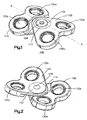
- Fig. 1 illustrates a top perspective view of an assembled plate according to a first preferred embodiment of the present invention
- Fig. 2 illustrates a bottom perspective view of the assembled plate of Fig. 1 ;
- Figs. 3A illustrates a cross-sectional view of the assembled plate of Fig. 1 , taken generally perpendicular to a longitudinal axis of the plate and through a central screw;
- Fig. 3B illustrates a magnified cross-sectional view taken adjacent the central screw of Fig. 3A ;
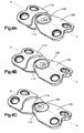
- Fig. 4A illustrates a top perspective view of the assembled plate of Fig. 1 with upper and lower plates slightly reshaped and resized;
- Fig. 4B illustrates a top perspective view of the assembled plate of Fig. 4A in a partially expanded position
- Fig. 4C illustrates a top perspective view of the assembled plate of Fig. 4A in a fully expanded position
- Fig. 5A illustrates a top plan, partially exploded view of the assembled plate of Fig. 4A with upper and lower plates slightly reshaped and resized;
- Fig. 5B illustrates a top plan, partially exploded view of the assembled plate of Fig. 4B with upper and lower plates slightly reshaped and resized;
- Fig. 5C illustrates a top plan, partially exploded view of the assembled plate of Fig. 4C with upper and lower plates slightly reshaped and resized;
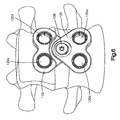
- Fig. 6 illustrates a top perspective view of the plate of Fig. 1 mounted to an anterior portion of a spine
- Preferred embodiments of the present invention are directed to a cervical anterior transpedicular screw-and-plate system.
- the preferred embodiments of the screw-and-plate system are not limited to applications or mounting in the anterior spine and may be utilized in the lumbar spine or for mounting to other bones in the human body, as would be apparent to one having ordinary skill in the art.
- the plates described herein may be used in spinal fusion procedures in which a damaged or diseased disc (or part of a disc) is removed from between a pair of vertebrae and a spinal fusion spacer is placed between the vertebrae.
- the plates are applied to an anterior portion of the affected vertebrae to span the affected disc space, and may be fixed to the vertebrae using bone screws as will be described in more detail below.
- the plate functions to maintain the vertebrae aligned during the initial period following fixation in which fusion of the spacer to the adjacent vertebrae occurs.
- the plate may also function to share some of the axial spinal load applied to the fusion spacer to prevent extreme subsidence of the spacer into the vertebral body, such as where the patient has poor bone quality.
- the plates may also act to prevent the spacer from being expelled from the disc space during the initial post-operative period.
- the plates may be used for single level (i.e. one-disc) fusion procedures, although in second and third preferred embodiments, the plates are used in multiple-level (i.e. multiple discs) fusion procedures. Some embodiments may be used for corpectomy procedures, in which at least a portion of a vertebral body is removed. While the plates herein are described with reference and application to the spine, it will be appreciated that features of the plates and the plates may have other applications, and can be applied to other bones and/or parts of the skeleton.
- a first embodiment of the system includes a locking plate 100, which has an upper plate 105, a lower plate 110, and a longitudinal axis A-A.
- the upper plate 105 has a rotatable, ring-shaped eccentric member 112, which contains an off-center aperture 106
- the lower plate 110 has a rotatable ring-shaped eccentric member 114 that contains an off-center aperture 107 for rotatably interconnecting the upper plate 105 to the lower plate 110 via a central screw 108.
- the first preferred embodiment of locking plate 100 includes two fastener holes 120a, 120b at an end of upper plate 105 and two fastener holes 120c and 120d at an end of lower plate 110.
- the fastener holes 120a, 120b, 120c, 120d may be configured to receive at least a portion of a bone fastener (See, for example, bone fastener 715 (Fig. 7B)), which may be inserted into a bone segment, such as a vertebral body (See Figs. 6 and 9).
- a bone fastener See, for example, bone fastener 715 (Fig. 7B)
- a vertebral body See Figs. 6 and 9.
- the plate 100 is shown with two pairs of fixation holes 120a, 120b, 120c, 120d, more than two pairs may be provided, for example so that plate 100 may span a greater length and thus be fastened to multiple locations along the spine or across multiple levels.
- Single holes may be provided as opposed to the pairs of fastener holes 120a, 120b, 120c, 120d.
- each fastener hole 120a, 120b, 120c, 120d may contain a compression ring (not shown), as would be apparent to one having ordinary skill in the art, to receive the bone fasteners and the plate 100 may also have one or more visualization windows (not shown) extending from the upper surface of upper plate 105 through the lower surface of upper plate 105.
- the window may provide visual access to a disc space below the plate 100 when implanted into a patient's body.
- Fig. 2 shows the under surface of the upper and lower plates 105, 110 in more detail.
- the upper plate 105 is rotatably interconnected with the lower plate 110 via the insertion of the central screw 108 through both of the off-center apertures 106, 107 of the upper and lower plates 105, 110. Once the screw 108 is fully inserted through both of the off-center apertures 106, 107, the upper and lower plates 105 and 110 are secured to each other.
- contact areas or surfaces 116, 117 of the upper plate 105 and contact areas or surfaces 118, 119 of lower plate 110 that contact each other in an assembled configuration may include a certain roughness, which allows the contact surfaces 116, 117, 118, 119 to exert friction relative to each other so that when the screw 108 is inserted though through the off-center apertures 106, 107 in the ring-shaped eccentric members 112, 114, the upper plate 105 and the lower plate 110 are secured to each other, thereby controlling the transverse sliding of the lower plate 105 with respect to the upper plate 110 along the longitudinal axis A-A of the plate 100.
- Each of the eccentric members 112, 114 are preferably rotatable relative to their respective upper and lower plates 105, 110.
- the screw plate 100 has its minimum length along the longitudinal axis A-A.
- the off-center eccentric members 112, 114 can be rotated individually or in concert to allow the upper and lower plates 105, 110 to translate relative to each other.
- the off-center eccentric member 112 of the upper plate 105 is rotated, thereby moving the off-center aperture 106 further away from the distal end of the upper plate 105 and closer to the distal end of the lower plate 110, the upper plate 105 is translated away from the lower plate 105 creating a greater length along the longitudinal axis A-A of the plate 100.
- the off-center eccentric members 112, 114 are rotated in varying degrees, the length of the plate 100 along the longitudinal axis A-A is varied. As can be seen in Figs.
- the upper and lower plates 105, 110 can attain varying horizontal translation relative to each other and the longitudinal axis A-A by rotating either or both of the eccentric members 112, 114 so that the apertures 106, 107 are positioned at various locations along a horizontal axis of plate 100, wherein the horizontal axis is generally perpendicular to the longitudinal axis A-A.
- the use of the eccentric members 112, 114 of the plate 100 of the first preferred embodiment enables the use a limited number of different bone plates to account for the differing dimensions of a patient's anatomy. For instance, the below calculation illustrates how it is possible, through the rotation of the eccentric members 112, 114, to encompass a vast array of vertical distances with a limited number of plates.
- the maximal variability of the plate 100 along the longitudinal axis A-A would equal two times the eccentricity of the eccentric member 112 of the upper plate 105 plus two (2) times the eccentricity of the eccentric member 114 of the lower plate 110 ((2*eccentricity 112) + (2*eccentricity 114)).
- the length of the plate 100 along the longitudinal axis A-A can be varied by rotating each or both of the eccentric members 112, 114 resulting in a single plate 100 that can be used for patients with varying anatomical dimensions.
- the plate 100 In use, for implantation of the plate 100 in the middle and lower cervical spine, an anterolateral approach is preferred. If the plate 100 is to be extended over several segments of the spine, a long incision is preferred. When exposing the vertebral bodies, the anterior longitudinal ligament is preferably removed or incised only in the areas where the intervertebral disc is to be bridged by the plate 100. Such a technique limits damage to the anterior longitudinal ligament in adjacent segments.
- an image intensifier tool such as Fluoroscopy (not shown) may be used to guide and monitor guide wires which are placed in the vertebra, preferably from the anterior side.
- an image intensifier tool such as Fluoroscopy (not shown)
- the cranial and caudal end-segments of the spine are spread and a corpectomy implant or natural bone is implanted to replace the removed segments.
- the distance between the guide wires is measured with, for example, a caliper instrument (not shown), which measurement can be utilized to determine plate size.
- the plate 100 is preferably adjusted to the ideal length by rotating the eccentric members 112, 114 of the upper and lower plates 105, 110 and the adjusted plate 100 is placed over the guide wires. Once the proper size has been determined, before or after screws or fasteners have been inserted into the patient, the plate 100 is preferably locked by tightening the central screw 108.
- cannulated screws are preferably guided over the guide wires and inserted through the fastener holes 120a, 120b, 120c, 120d.
- cannulated screws are preferably used, any heretofore known or hereafter developed means of fixation can be used.
- cortical, pedicle or spongiosa screws may be placed into the vertebral body to fasten the plate 100 thereto.
- the screws can be locked using locking screws.
- An exemplary use of locking screws is disclosed in U.S. Patent No. 6,235,033 , entitled "Bone Fixation Assembly".
Claims (5)
- Knochenfixationsvorrichtung (100) mit einer zentralen Längsachse umfassend:eine erste Platte (105) mit einer Oberseite und einer Unterseite, und mindestens einem Befestigungsloch (120a, 120b), welches zur Aufnahme mindestens eines Abschnitts eines ersten Knochenfixationselements ausgebildet ist, wobei sich das Befestigungsloch von der Oberseite bis zur Unterseite erstreckt, undeine zweite Platte (110) mit einer Oberseite und einer Unterseite, und mindestens einem Befestigungsloch (120c, 120d), welches zur Aufnahme mindestens eines Abschnitts eines zweiten Knochenfixationselements ausgebildet ist, wobei sich das Befestigungsloch von der Oberseite bis zur Unterseite erstreckt,
dadurch gekennzeichnet, dassdie erste Platte (105) zusätzlich ein erstes drehbares Exzenterteil (112) umfasst, wobei das erste Exzenterteil eine erste Öffnung (106) zur Aufnahme mindestens eines Teils eines zentralen Befestigungselements aufweist; unddie zweite Platte (110) zusätzlich ein zweites drehbares Exzenterteil (114) umfasst, wobei das zweite Exzenterteil eine zweite Öffnung (107) zur Aufnahme mindestens eines Teils des zentralen Befestigungselements aufweist, wobeidas erste und zweite drehbare Exzenterteil ermöglichen, dass sich die erste Platte und die zweite Platte relativ zueinander vertikal verschieben können, und wobei die Ausrichtung der ersten Platte relativ zur zweiten Platte durch Vorwärtsbewegen des zentralen Befestigungselements durch die erste und zweite Öffnung fixierbar ist. - Knochenfixationsvorrichtung nach Anspruch 1, dadurch gekennzeichnet, dass das erste und zweite drehbare Exzenterteil zusätzlich ermöglichen, dass die erste Platte und die zweite Platte eine horizontale Verschiebung relativ zueinander erfahren.
- Knochenfixationsvorrichtung nach Anspruch 1, dadurch gekennzeichnet, dass die Knochenfixationsvorrichtung ihre maximale Länge entlang der zentralen Längsachse erreicht, wenn die erste Öffnung in ihrer entlang der zentralen Längsachse am weitesten von dem mindestens einen Befestigungsloch der oberen Platte entfernten Position ist und die zweite Öffnung in ihrer entlang der zentralen Längsachse am weitesten von dem mindestens einen Befestigungsloch der unteren Platte entfernten Position ist.
- Knochenfixationsvorrichtung nach Anspruch 1, dadurch gekennzeichnet, dass die Knochenfixationsvorrichtung ihre minimale Länge entlang der zentralen Längsachse erreicht, wenn die erste Öffnung in ihrer entlang der zentralen Längsachse am nächsten bei dem mindestens einen Befestigungsloch der oberen Platte liegenden Position ist und die zweite Öffnung in ihrer entlang der zentralen Längsachse am nächsten bei dem mindestens einen Befestigungsloch der unteren Platte liegenden Position ist.
- Knochenfixationsvorrichtung nach Anspruch 1, dadurch gekennzeichnet, dass mindestens ein Teil der Unterseite der oberen Platte und mindestens ein Teil der Oberseite der unteren Platte eine Rauhigkeit aufweisen, welche Reibung zwischen diesen Teilen ermöglicht, wenn das zentrale Befestigungselement durch die erste und zweite Öffnung eingeführt ist.
Applications Claiming Priority (2)
| Application Number | Priority Date | Filing Date | Title |
|---|---|---|---|
| US9803608P | 2008-09-18 | 2008-09-18 | |
| PCT/US2009/057454 WO2010033786A2 (en) | 2008-09-18 | 2009-09-18 | Anterior transpedicular screw-and-plate system |
Related Child Applications (1)
| Application Number | Title | Priority Date | Filing Date |
|---|---|---|---|
| EP11004993.9 Division-Into | 2011-06-20 |
Publications (2)
| Publication Number | Publication Date |
|---|---|
| EP2323573A2 EP2323573A2 (de) | 2011-05-25 |
| EP2323573B1 true EP2323573B1 (de) | 2012-01-18 |
Family
ID=41528794
Family Applications (2)
| Application Number | Title | Priority Date | Filing Date |
|---|---|---|---|
| EP11004993A Withdrawn EP2368506A1 (de) | 2008-09-18 | 2009-09-18 | Anteriores transpedikuläres Schrauben-Platten-System |
| EP09792704A Not-in-force EP2323573B1 (de) | 2008-09-18 | 2009-09-18 | Anteriores transpedikuläres schrauben-platten-system |
Family Applications Before (1)
| Application Number | Title | Priority Date | Filing Date |
|---|---|---|---|
| EP11004993A Withdrawn EP2368506A1 (de) | 2008-09-18 | 2009-09-18 | Anteriores transpedikuläres Schrauben-Platten-System |
Country Status (9)
| Country | Link |
|---|---|
| US (1) | US20120022600A1 (de) |
| EP (2) | EP2368506A1 (de) |
| JP (1) | JP2012502760A (de) |
| KR (1) | KR20110069073A (de) |
| CN (1) | CN102159149A (de) |
| AT (1) | ATE541525T1 (de) |
| BR (1) | BRPI0918606A2 (de) |
| CA (1) | CA2735683A1 (de) |
| WO (1) | WO2010033786A2 (de) |
Families Citing this family (40)
| Publication number | Priority date | Publication date | Assignee | Title |
|---|---|---|---|---|
| US9039768B2 (en) | 2006-12-22 | 2015-05-26 | Medos International Sarl | Composite vertebral spacers and instrument |
| US20090248092A1 (en) | 2008-03-26 | 2009-10-01 | Jonathan Bellas | Posterior Intervertebral Disc Inserter and Expansion Techniques |
| US9526620B2 (en) | 2009-03-30 | 2016-12-27 | DePuy Synthes Products, Inc. | Zero profile spinal fusion cage |
| US9393129B2 (en) | 2009-12-10 | 2016-07-19 | DePuy Synthes Products, Inc. | Bellows-like expandable interbody fusion cage |
| US11529241B2 (en) | 2010-09-23 | 2022-12-20 | DePuy Synthes Products, Inc. | Fusion cage with in-line single piece fixation |
| US20120078373A1 (en) | 2010-09-23 | 2012-03-29 | Thomas Gamache | Stand alone intervertebral fusion device |
| US20120078372A1 (en) | 2010-09-23 | 2012-03-29 | Thomas Gamache | Novel implant inserter having a laterally-extending dovetail engagement feature |
| EP2693963B1 (de) | 2011-04-01 | 2015-06-03 | Synthes GmbH | System zur glättung der hinteren rückenwirbel |
| US11123117B1 (en) | 2011-11-01 | 2021-09-21 | Nuvasive, Inc. | Surgical fixation system and related methods |
| CA2857992C (en) * | 2011-12-09 | 2018-08-14 | Zimmer Gmbh | Orthopedic plate, orthopedic device, method of coupling bone segments, and method of assembling an orthopedic plate |
| US20170348030A1 (en) * | 2011-12-09 | 2017-12-07 | Steve L. Haddad | Orthopedic plate, orthopedic device, method of coupling bone segments, and method of assembling an orthopedic plate |
| EP2623058A3 (de) | 2012-02-06 | 2013-09-11 | Crcaholic S.A. | Befestigungsvorrichtung und Werkzeug für chirurgische Haltesysteme |
| US9271836B2 (en) | 2012-03-06 | 2016-03-01 | DePuy Synthes Products, Inc. | Nubbed plate |
| US10485592B2 (en) | 2012-05-10 | 2019-11-26 | Spinal Simplicity, Llc | Locking fastener for use with dynamic bone fracture plates |
| US8974504B2 (en) | 2012-05-10 | 2015-03-10 | Spinal Simplicity Llc | Dynamic bone fracture plates |
| AU2013259272B2 (en) * | 2012-05-10 | 2018-01-18 | Spinal Simplicity Llc | Dynamic bone fracture plates |
| KR101331428B1 (ko) * | 2012-08-03 | 2013-11-21 | 주식회사 솔고 바이오메디칼 | 나사의 진입각도를 추종하는 경추고정장치 |
| US10182921B2 (en) | 2012-11-09 | 2019-01-22 | DePuy Synthes Products, Inc. | Interbody device with opening to allow packing graft and other biologics |
| WO2015095126A1 (en) | 2013-12-20 | 2015-06-25 | Hartdegen Vernon | Polyaxial locking hole |
| JP6594946B2 (ja) * | 2014-07-03 | 2019-10-23 | アキュームド・エルエルシー | 移動可能な継手を備える骨プレート |
| US11202626B2 (en) | 2014-07-10 | 2021-12-21 | Crossroads Extremity Systems, Llc | Bone implant with means for multi directional force and means of insertion |
| AU2015287901A1 (en) | 2014-07-10 | 2017-02-23 | Crossroads Extremity Systems, Llc | Bone implant and means of insertion |
| US10213237B2 (en) * | 2014-10-03 | 2019-02-26 | Stryker European Holdings I, Llc | Periprosthetic extension plate |
| USD779065S1 (en) | 2014-10-08 | 2017-02-14 | Nuvasive, Inc. | Anterior cervical bone plate |
| AU2016294449B2 (en) * | 2015-07-13 | 2018-03-22 | Crossroads Extremity Systems, Llc | Bone plates with dynamic elements |
| WO2017035031A1 (en) * | 2015-08-21 | 2017-03-02 | Scott Meyer | Pedicle screw placement system and method for spinal surgery |
| US20170181779A1 (en) * | 2015-12-29 | 2017-06-29 | Orthohelix Surgical Designs, Inc. | Active compression plate and method for its use |
| EP3320867B1 (de) * | 2016-11-14 | 2021-08-04 | Biedermann Technologies GmbH & Co. KG | Modulare knochenplatte und element solch einer modularen knochenplatte |
| US11864753B2 (en) | 2017-02-06 | 2024-01-09 | Crossroads Extremity Systems, Llc | Implant inserter |
| EP3579762A4 (de) | 2017-02-07 | 2021-04-07 | Crossroads Extremity Systems, LLC | Gegendrehmoment-implantat |
| US10940016B2 (en) | 2017-07-05 | 2021-03-09 | Medos International Sarl | Expandable intervertebral fusion cage |
| CN107753095A (zh) * | 2017-11-17 | 2018-03-06 | 常州集硕医疗器械有限公司 | 一种可与棒结合式脊柱板 |
| JP6960055B2 (ja) * | 2018-06-12 | 2021-11-05 | オリンパステルモバイオマテリアル株式会社 | 骨手術用器具 |
| KR102553035B1 (ko) | 2018-06-12 | 2023-07-07 | 올림푸스 테루모 바이오머티리얼 가부시키가이샤 | 골 플레이트 및 골 플레이트 키트 |
| WO2020158998A1 (ko) * | 2019-01-29 | 2020-08-06 | 고려대학교 산학협력단 | 골절치료용 고정유닛 및 이에 사용되는 골절치료용 견인유닛과 골나사 |
| CN109965967B (zh) * | 2019-05-08 | 2022-05-06 | 天津市康尔医疗器械有限公司 | 颅颌面接骨板 |
| US11389209B2 (en) | 2019-07-19 | 2022-07-19 | Medos International Sarl | Surgical plating systems, devices, and related methods |
| USD961081S1 (en) | 2020-11-18 | 2022-08-16 | Crossroads Extremity Systems, Llc | Orthopedic implant |
| PL244435B1 (pl) * | 2021-08-09 | 2024-01-29 | Univ Zielonogorski | Zestaw elementów do osteotomii, z możliwością łączenia się między sobą i rozbudowy |
| PL244434B1 (pl) * | 2021-08-09 | 2024-01-29 | Univ Zielonogorski | Zestaw elementów do osteotomii, z możliwością łączenia się między sobą i rozbudowy |
Family Cites Families (22)
| Publication number | Priority date | Publication date | Assignee | Title |
|---|---|---|---|---|
| US1811363A (en) * | 1929-05-22 | 1931-06-23 | Henry E Morton | Milling machine |
| US2096116A (en) * | 1934-02-16 | 1937-10-19 | Leighton John Wycliffe | Independent wheel suspension |
| US1987661A (en) * | 1934-04-06 | 1935-01-15 | Frederick J Blauvelt | Variable connection between crank and piston |
| CH645264A5 (de) * | 1980-05-28 | 1984-09-28 | Straumann Inst Ag | Einrichtung mit einer platte und zu deren befestigung an einem knochen dienenden schrauben. |
| US6206397B1 (en) * | 1995-01-25 | 2001-03-27 | James B. Klassen | Bicycle wheel travel path for selectively applying chainstay lengthening effect and apparatus for providing same |
| DE29521456U1 (de) * | 1995-12-07 | 1997-05-07 | Aesculap Ag | Orthopädisches Haltesystem |
| WO2000057074A1 (de) * | 1999-03-24 | 2000-09-28 | Fev Motorentechnik Gmbh | Kupplungselement zur verbindung von zwei gleichachsig hintereinander und mit querabstand zueinander angeordneten achsparallelen wellen |
| US6235033B1 (en) | 2000-04-19 | 2001-05-22 | Synthes (Usa) | Bone fixation assembly |
| US6641583B2 (en) * | 2001-03-29 | 2003-11-04 | Endius Incorporated | Apparatus for retaining bone portions in a desired spatial relationship |
| US7041105B2 (en) * | 2001-06-06 | 2006-05-09 | Sdgi Holdings, Inc. | Dynamic, modular, multilock anterior cervical plate system having detachably fastened assembleable and moveable segments |
| US7303564B2 (en) * | 2002-02-01 | 2007-12-04 | Spinal Concepts, Inc. | Spinal plate extender system and method |
| US6695846B2 (en) * | 2002-03-12 | 2004-02-24 | Spinal Innovations, Llc | Bone plate and screw retaining mechanism |
| WO2004045389A2 (en) * | 2002-11-19 | 2004-06-03 | Acumed Llc | Adjustable bone plates |
| US20050049595A1 (en) * | 2003-09-03 | 2005-03-03 | Suh Sean S. | Track-plate carriage system |
| US8167917B2 (en) * | 2003-09-24 | 2012-05-01 | Spinefrontier Lls | Apparatus and method for spine fixation |
| US7488327B2 (en) * | 2004-04-12 | 2009-02-10 | Synthes (U.S.A.) | Free hand drill guide |
| US8025681B2 (en) * | 2006-03-29 | 2011-09-27 | Theken Spine, Llc | Dynamic motion spinal stabilization system |
| US8257355B2 (en) * | 2006-06-07 | 2012-09-04 | Spinefrontier Inc. | Methods and devices for static or dynamic spine stabilization |
| US20080039847A1 (en) * | 2006-08-09 | 2008-02-14 | Mark Piper | Implant and system for stabilization of the spine |
| GB0623801D0 (en) * | 2006-11-29 | 2007-01-10 | Surgicraft Ltd | Orthopaedic implants and prosthesis |
| DE202007001585U1 (de) * | 2007-01-30 | 2007-05-10 | Zrinski Ag | Plattenimplantat, insbesondere für die Anwendung an einer Wirbelsäule |
| US8287574B2 (en) * | 2008-08-06 | 2012-10-16 | The University Of Toledo | Cervical plate assembly |
-
2009
- 2009-09-18 BR BRPI0918606A patent/BRPI0918606A2/pt not_active IP Right Cessation
- 2009-09-18 EP EP11004993A patent/EP2368506A1/de not_active Withdrawn
- 2009-09-18 CN CN200980136491XA patent/CN102159149A/zh active Pending
- 2009-09-18 KR KR1020117008417A patent/KR20110069073A/ko not_active Application Discontinuation
- 2009-09-18 AT AT09792704T patent/ATE541525T1/de active
- 2009-09-18 JP JP2011527989A patent/JP2012502760A/ja not_active Ceased
- 2009-09-18 WO PCT/US2009/057454 patent/WO2010033786A2/en active Application Filing
- 2009-09-18 US US13/119,830 patent/US20120022600A1/en not_active Abandoned
- 2009-09-18 CA CA2735683A patent/CA2735683A1/en not_active Abandoned
- 2009-09-18 EP EP09792704A patent/EP2323573B1/de not_active Not-in-force
Also Published As
| Publication number | Publication date |
|---|---|
| JP2012502760A (ja) | 2012-02-02 |
| WO2010033786A3 (en) | 2010-06-24 |
| US20120022600A1 (en) | 2012-01-26 |
| EP2323573A2 (de) | 2011-05-25 |
| WO2010033786A2 (en) | 2010-03-25 |
| EP2368506A1 (de) | 2011-09-28 |
| CN102159149A (zh) | 2011-08-17 |
| CA2735683A1 (en) | 2010-03-25 |
| BRPI0918606A2 (pt) | 2018-10-09 |
| ATE541525T1 (de) | 2012-02-15 |
| KR20110069073A (ko) | 2011-06-22 |
Similar Documents
| Publication | Publication Date | Title |
|---|---|---|
| EP2323573B1 (de) | Anteriores transpedikuläres schrauben-platten-system | |
| US11179246B2 (en) | Intervertebral implant | |
| US9987141B2 (en) | Intervertebral fusion implant | |
| US10575960B2 (en) | Intervertebral fusion implant | |
| US9320549B2 (en) | Spinal fixation plates | |
| EP2346423B1 (de) | Posteriores dynamisches stabilisationssystem | |
| US9480510B2 (en) | Devices, systems and methods of attaching same to the spine | |
| AU2010237054A1 (en) | Interspinous spacer and facet joint fixation device | |
| AU2005206822A1 (en) | Pedicle screw constructs for spine fixation systems | |
| US20120065688A1 (en) | Low-profile anterior vertebral plate assemblies and methods of use |
Legal Events
| Date | Code | Title | Description |
|---|---|---|---|
| PUAI | Public reference made under article 153(3) epc to a published international application that has entered the european phase |
Free format text: ORIGINAL CODE: 0009012 |
|
| 17P | Request for examination filed |
Effective date: 20110226 |
|
| AK | Designated contracting states |
Kind code of ref document: A2 Designated state(s): AT BE BG CH CY CZ DE DK EE ES FI FR GB GR HR HU IE IS IT LI LT LU LV MC MK MT NL NO PL PT RO SE SI SK SM TR |
|
| AX | Request for extension of the european patent |
Extension state: AL BA RS |
|
| DAC | Divisional application: reference to earlier application (deleted) | ||
| GRAP | Despatch of communication of intention to grant a patent |
Free format text: ORIGINAL CODE: EPIDOSNIGR1 |
|
| DAX | Request for extension of the european patent (deleted) | ||
| GRAS | Grant fee paid |
Free format text: ORIGINAL CODE: EPIDOSNIGR3 |
|
| GRAA | (expected) grant |
Free format text: ORIGINAL CODE: 0009210 |
|
| AK | Designated contracting states |
Kind code of ref document: B1 Designated state(s): AT BE BG CH CY CZ DE DK EE ES FI FR GB GR HR HU IE IS IT LI LT LU LV MC MK MT NL NO PL PT RO SE SI SK SM TR |
|
| REG | Reference to a national code |
Ref country code: GB Ref legal event code: FG4D |
|
| REG | Reference to a national code |
Ref country code: CH Ref legal event code: EP |
|
| REG | Reference to a national code |
Ref country code: CH Ref legal event code: NV Representative=s name: DR. LUSUARDI AG Ref country code: AT Ref legal event code: REF Ref document number: 541525 Country of ref document: AT Kind code of ref document: T Effective date: 20120215 Ref country code: IE Ref legal event code: FG4D |
|
| REG | Reference to a national code |
Ref country code: DE Ref legal event code: R096 Ref document number: 602009004827 Country of ref document: DE Effective date: 20120322 |
|
| REG | Reference to a national code |
Ref country code: NL Ref legal event code: VDEP Effective date: 20120118 |
|
| LTIE | Lt: invalidation of european patent or patent extension |
Effective date: 20120118 |
|
| PG25 | Lapsed in a contracting state [announced via postgrant information from national office to epo] |
Ref country code: HR Free format text: LAPSE BECAUSE OF FAILURE TO SUBMIT A TRANSLATION OF THE DESCRIPTION OR TO PAY THE FEE WITHIN THE PRESCRIBED TIME-LIMIT Effective date: 20120118 Ref country code: LT Free format text: LAPSE BECAUSE OF FAILURE TO SUBMIT A TRANSLATION OF THE DESCRIPTION OR TO PAY THE FEE WITHIN THE PRESCRIBED TIME-LIMIT Effective date: 20120118 Ref country code: BG Free format text: LAPSE BECAUSE OF FAILURE TO SUBMIT A TRANSLATION OF THE DESCRIPTION OR TO PAY THE FEE WITHIN THE PRESCRIBED TIME-LIMIT Effective date: 20120418 Ref country code: IS Free format text: LAPSE BECAUSE OF FAILURE TO SUBMIT A TRANSLATION OF THE DESCRIPTION OR TO PAY THE FEE WITHIN THE PRESCRIBED TIME-LIMIT Effective date: 20120518 Ref country code: BE Free format text: LAPSE BECAUSE OF FAILURE TO SUBMIT A TRANSLATION OF THE DESCRIPTION OR TO PAY THE FEE WITHIN THE PRESCRIBED TIME-LIMIT Effective date: 20120118 Ref country code: NL Free format text: LAPSE BECAUSE OF FAILURE TO SUBMIT A TRANSLATION OF THE DESCRIPTION OR TO PAY THE FEE WITHIN THE PRESCRIBED TIME-LIMIT Effective date: 20120118 Ref country code: NO Free format text: LAPSE BECAUSE OF FAILURE TO SUBMIT A TRANSLATION OF THE DESCRIPTION OR TO PAY THE FEE WITHIN THE PRESCRIBED TIME-LIMIT Effective date: 20120418 |
|
| PG25 | Lapsed in a contracting state [announced via postgrant information from national office to epo] |
Ref country code: GR Free format text: LAPSE BECAUSE OF FAILURE TO SUBMIT A TRANSLATION OF THE DESCRIPTION OR TO PAY THE FEE WITHIN THE PRESCRIBED TIME-LIMIT Effective date: 20120419 Ref country code: FI Free format text: LAPSE BECAUSE OF FAILURE TO SUBMIT A TRANSLATION OF THE DESCRIPTION OR TO PAY THE FEE WITHIN THE PRESCRIBED TIME-LIMIT Effective date: 20120118 Ref country code: PL Free format text: LAPSE BECAUSE OF FAILURE TO SUBMIT A TRANSLATION OF THE DESCRIPTION OR TO PAY THE FEE WITHIN THE PRESCRIBED TIME-LIMIT Effective date: 20120118 Ref country code: PT Free format text: LAPSE BECAUSE OF FAILURE TO SUBMIT A TRANSLATION OF THE DESCRIPTION OR TO PAY THE FEE WITHIN THE PRESCRIBED TIME-LIMIT Effective date: 20120518 Ref country code: LV Free format text: LAPSE BECAUSE OF FAILURE TO SUBMIT A TRANSLATION OF THE DESCRIPTION OR TO PAY THE FEE WITHIN THE PRESCRIBED TIME-LIMIT Effective date: 20120118 |
|
| REG | Reference to a national code |
Ref country code: AT Ref legal event code: MK05 Ref document number: 541525 Country of ref document: AT Kind code of ref document: T Effective date: 20120118 |
|
| PG25 | Lapsed in a contracting state [announced via postgrant information from national office to epo] |
Ref country code: CY Free format text: LAPSE BECAUSE OF FAILURE TO SUBMIT A TRANSLATION OF THE DESCRIPTION OR TO PAY THE FEE WITHIN THE PRESCRIBED TIME-LIMIT Effective date: 20120118 |
|
| PG25 | Lapsed in a contracting state [announced via postgrant information from national office to epo] |
Ref country code: SE Free format text: LAPSE BECAUSE OF FAILURE TO SUBMIT A TRANSLATION OF THE DESCRIPTION OR TO PAY THE FEE WITHIN THE PRESCRIBED TIME-LIMIT Effective date: 20120118 Ref country code: SI Free format text: LAPSE BECAUSE OF FAILURE TO SUBMIT A TRANSLATION OF THE DESCRIPTION OR TO PAY THE FEE WITHIN THE PRESCRIBED TIME-LIMIT Effective date: 20120118 Ref country code: DK Free format text: LAPSE BECAUSE OF FAILURE TO SUBMIT A TRANSLATION OF THE DESCRIPTION OR TO PAY THE FEE WITHIN THE PRESCRIBED TIME-LIMIT Effective date: 20120118 Ref country code: RO Free format text: LAPSE BECAUSE OF FAILURE TO SUBMIT A TRANSLATION OF THE DESCRIPTION OR TO PAY THE FEE WITHIN THE PRESCRIBED TIME-LIMIT Effective date: 20120118 Ref country code: EE Free format text: LAPSE BECAUSE OF FAILURE TO SUBMIT A TRANSLATION OF THE DESCRIPTION OR TO PAY THE FEE WITHIN THE PRESCRIBED TIME-LIMIT Effective date: 20120118 Ref country code: CZ Free format text: LAPSE BECAUSE OF FAILURE TO SUBMIT A TRANSLATION OF THE DESCRIPTION OR TO PAY THE FEE WITHIN THE PRESCRIBED TIME-LIMIT Effective date: 20120118 |
|
| PLBE | No opposition filed within time limit |
Free format text: ORIGINAL CODE: 0009261 |
|
| STAA | Information on the status of an ep patent application or granted ep patent |
Free format text: STATUS: NO OPPOSITION FILED WITHIN TIME LIMIT |
|
| PG25 | Lapsed in a contracting state [announced via postgrant information from national office to epo] |
Ref country code: SK Free format text: LAPSE BECAUSE OF FAILURE TO SUBMIT A TRANSLATION OF THE DESCRIPTION OR TO PAY THE FEE WITHIN THE PRESCRIBED TIME-LIMIT Effective date: 20120118 |
|
| 26N | No opposition filed |
Effective date: 20121019 |
|
| PGFP | Annual fee paid to national office [announced via postgrant information from national office to epo] |
Ref country code: DE Payment date: 20120912 Year of fee payment: 4 Ref country code: IT Payment date: 20120930 Year of fee payment: 4 Ref country code: FR Payment date: 20120926 Year of fee payment: 4 |
|
| PG25 | Lapsed in a contracting state [announced via postgrant information from national office to epo] |
Ref country code: AT Free format text: LAPSE BECAUSE OF FAILURE TO SUBMIT A TRANSLATION OF THE DESCRIPTION OR TO PAY THE FEE WITHIN THE PRESCRIBED TIME-LIMIT Effective date: 20120118 |
|
| REG | Reference to a national code |
Ref country code: DE Ref legal event code: R097 Ref document number: 602009004827 Country of ref document: DE Effective date: 20121019 |
|
| PG25 | Lapsed in a contracting state [announced via postgrant information from national office to epo] |
Ref country code: ES Free format text: LAPSE BECAUSE OF FAILURE TO SUBMIT A TRANSLATION OF THE DESCRIPTION OR TO PAY THE FEE WITHIN THE PRESCRIBED TIME-LIMIT Effective date: 20120429 Ref country code: MC Free format text: LAPSE BECAUSE OF NON-PAYMENT OF DUE FEES Effective date: 20120930 |
|
| REG | Reference to a national code |
Ref country code: IE Ref legal event code: MM4A |
|
| PG25 | Lapsed in a contracting state [announced via postgrant information from national office to epo] |
Ref country code: IE Free format text: LAPSE BECAUSE OF NON-PAYMENT OF DUE FEES Effective date: 20120918 |
|
| PG25 | Lapsed in a contracting state [announced via postgrant information from national office to epo] |
Ref country code: MT Free format text: LAPSE BECAUSE OF FAILURE TO SUBMIT A TRANSLATION OF THE DESCRIPTION OR TO PAY THE FEE WITHIN THE PRESCRIBED TIME-LIMIT Effective date: 20120118 |
|
| PG25 | Lapsed in a contracting state [announced via postgrant information from national office to epo] |
Ref country code: TR Free format text: LAPSE BECAUSE OF FAILURE TO SUBMIT A TRANSLATION OF THE DESCRIPTION OR TO PAY THE FEE WITHIN THE PRESCRIBED TIME-LIMIT Effective date: 20120118 |
|
| REG | Reference to a national code |
Ref country code: CH Ref legal event code: PL |
|
| GBPC | Gb: european patent ceased through non-payment of renewal fee |
Effective date: 20130918 |
|
| PG25 | Lapsed in a contracting state [announced via postgrant information from national office to epo] |
Ref country code: SM Free format text: LAPSE BECAUSE OF FAILURE TO SUBMIT A TRANSLATION OF THE DESCRIPTION OR TO PAY THE FEE WITHIN THE PRESCRIBED TIME-LIMIT Effective date: 20120118 Ref country code: LU Free format text: LAPSE BECAUSE OF NON-PAYMENT OF DUE FEES Effective date: 20120918 |
|
| REG | Reference to a national code |
Ref country code: DE Ref legal event code: R119 Ref document number: 602009004827 Country of ref document: DE Effective date: 20140401 |
|
| REG | Reference to a national code |
Ref country code: FR Ref legal event code: ST Effective date: 20140530 |
|
| PG25 | Lapsed in a contracting state [announced via postgrant information from national office to epo] |
Ref country code: CH Free format text: LAPSE BECAUSE OF NON-PAYMENT OF DUE FEES Effective date: 20130930 Ref country code: LI Free format text: LAPSE BECAUSE OF NON-PAYMENT OF DUE FEES Effective date: 20130930 Ref country code: GB Free format text: LAPSE BECAUSE OF NON-PAYMENT OF DUE FEES Effective date: 20130918 Ref country code: HU Free format text: LAPSE BECAUSE OF FAILURE TO SUBMIT A TRANSLATION OF THE DESCRIPTION OR TO PAY THE FEE WITHIN THE PRESCRIBED TIME-LIMIT Effective date: 20090918 |
|
| PG25 | Lapsed in a contracting state [announced via postgrant information from national office to epo] |
Ref country code: IT Free format text: LAPSE BECAUSE OF NON-PAYMENT OF DUE FEES Effective date: 20130918 Ref country code: FR Free format text: LAPSE BECAUSE OF NON-PAYMENT OF DUE FEES Effective date: 20130930 Ref country code: DE Free format text: LAPSE BECAUSE OF NON-PAYMENT OF DUE FEES Effective date: 20140401 |
|
| PG25 | Lapsed in a contracting state [announced via postgrant information from national office to epo] |
Ref country code: MK Free format text: LAPSE BECAUSE OF FAILURE TO SUBMIT A TRANSLATION OF THE DESCRIPTION OR TO PAY THE FEE WITHIN THE PRESCRIBED TIME-LIMIT Effective date: 20120118 |