EP2323185A2 - Light emitting device and method for manufacturing the same - Google Patents
Light emitting device and method for manufacturing the same Download PDFInfo
- Publication number
- EP2323185A2 EP2323185A2 EP10177748A EP10177748A EP2323185A2 EP 2323185 A2 EP2323185 A2 EP 2323185A2 EP 10177748 A EP10177748 A EP 10177748A EP 10177748 A EP10177748 A EP 10177748A EP 2323185 A2 EP2323185 A2 EP 2323185A2
- Authority
- EP
- European Patent Office
- Prior art keywords
- phosphor
- light
- emitting device
- layer
- cavities
- Prior art date
- Legal status (The legal status is an assumption and is not a legal conclusion. Google has not performed a legal analysis and makes no representation as to the accuracy of the status listed.)
- Granted
Links
- 238000004519 manufacturing process Methods 0.000 title claims abstract description 20
- 238000000034 method Methods 0.000 title abstract description 11
- OAICVXFJPJFONN-UHFFFAOYSA-N Phosphorus Chemical compound [P] OAICVXFJPJFONN-UHFFFAOYSA-N 0.000 claims abstract description 141
- 239000002245 particle Substances 0.000 claims abstract description 68
- 239000004065 semiconductor Substances 0.000 claims abstract description 65
- 239000000463 material Substances 0.000 claims description 13
- 229920005989 resin Polymers 0.000 claims description 12
- 239000011347 resin Substances 0.000 claims description 12
- 239000000758 substrate Substances 0.000 claims description 9
- 238000001020 plasma etching Methods 0.000 claims description 5
- 238000001039 wet etching Methods 0.000 claims description 3
- 239000000853 adhesive Substances 0.000 claims description 2
- 230000001070 adhesive effect Effects 0.000 claims description 2
- 238000002156 mixing Methods 0.000 claims description 2
- 239000000203 mixture Substances 0.000 claims 2
- 239000002019 doping agent Substances 0.000 description 12
- 238000010586 diagram Methods 0.000 description 7
- 239000007788 liquid Substances 0.000 description 7
- 229910000980 Aluminium gallium arsenide Inorganic materials 0.000 description 5
- 230000004888 barrier function Effects 0.000 description 4
- 238000002347 injection Methods 0.000 description 4
- 239000007924 injection Substances 0.000 description 4
- 229910052751 metal Inorganic materials 0.000 description 4
- 239000002184 metal Substances 0.000 description 4
- 239000002699 waste material Substances 0.000 description 4
- 229910001218 Gallium arsenide Inorganic materials 0.000 description 3
- 239000003086 colorant Substances 0.000 description 3
- 150000001875 compounds Chemical class 0.000 description 3
- 230000000694 effects Effects 0.000 description 3
- 239000004038 photonic crystal Substances 0.000 description 3
- 229910052782 aluminium Inorganic materials 0.000 description 2
- 229910052788 barium Inorganic materials 0.000 description 2
- 229910052791 calcium Inorganic materials 0.000 description 2
- 229910052749 magnesium Inorganic materials 0.000 description 2
- 238000012986 modification Methods 0.000 description 2
- 230000004048 modification Effects 0.000 description 2
- 229910052712 strontium Inorganic materials 0.000 description 2
- 229910052718 tin Inorganic materials 0.000 description 2
- 229910052725 zinc Inorganic materials 0.000 description 2
- 229910045601 alloy Inorganic materials 0.000 description 1
- 239000000956 alloy Substances 0.000 description 1
- XAGFODPZIPBFFR-UHFFFAOYSA-N aluminium Chemical compound [Al] XAGFODPZIPBFFR-UHFFFAOYSA-N 0.000 description 1
- PNEYBMLMFCGWSK-UHFFFAOYSA-N aluminium oxide Inorganic materials [O-2].[O-2].[O-2].[Al+3].[Al+3] PNEYBMLMFCGWSK-UHFFFAOYSA-N 0.000 description 1
- 230000015572 biosynthetic process Effects 0.000 description 1
- 229910052593 corundum Inorganic materials 0.000 description 1
- 239000003822 epoxy resin Substances 0.000 description 1
- 238000000605 extraction Methods 0.000 description 1
- 239000002223 garnet Substances 0.000 description 1
- 238000000227 grinding Methods 0.000 description 1
- 150000004767 nitrides Chemical class 0.000 description 1
- 229910052763 palladium Inorganic materials 0.000 description 1
- 238000010587 phase diagram Methods 0.000 description 1
- 229910052697 platinum Inorganic materials 0.000 description 1
- 229920000647 polyepoxide Polymers 0.000 description 1
- 229920001296 polysiloxane Polymers 0.000 description 1
- 229910052703 rhodium Inorganic materials 0.000 description 1
- 150000004760 silicates Chemical class 0.000 description 1
- 229910052709 silver Inorganic materials 0.000 description 1
- 239000002904 solvent Substances 0.000 description 1
- 239000000126 substance Substances 0.000 description 1
- 150000003568 thioethers Chemical class 0.000 description 1
- 229910001845 yogo sapphire Inorganic materials 0.000 description 1
- 229910052727 yttrium Inorganic materials 0.000 description 1
- VWQVUPCCIRVNHF-UHFFFAOYSA-N yttrium atom Chemical compound [Y] VWQVUPCCIRVNHF-UHFFFAOYSA-N 0.000 description 1
Images


Classifications
-
- H—ELECTRICITY
- H01—ELECTRIC ELEMENTS
- H01L—SEMICONDUCTOR DEVICES NOT COVERED BY CLASS H10
- H01L33/00—Semiconductor devices with at least one potential-jump barrier or surface barrier specially adapted for light emission; Processes or apparatus specially adapted for the manufacture or treatment thereof or of parts thereof; Details thereof
- H01L33/48—Semiconductor devices with at least one potential-jump barrier or surface barrier specially adapted for light emission; Processes or apparatus specially adapted for the manufacture or treatment thereof or of parts thereof; Details thereof characterised by the semiconductor body packages
- H01L33/50—Wavelength conversion elements
- H01L33/508—Wavelength conversion elements having a non-uniform spatial arrangement or non-uniform concentration, e.g. patterned wavelength conversion layer, wavelength conversion layer with a concentration gradient of the wavelength conversion material
-
- H—ELECTRICITY
- H01—ELECTRIC ELEMENTS
- H01L—SEMICONDUCTOR DEVICES NOT COVERED BY CLASS H10
- H01L2933/00—Details relating to devices covered by the group H01L33/00 but not provided for in its subgroups
- H01L2933/0008—Processes
- H01L2933/0033—Processes relating to semiconductor body packages
- H01L2933/0041—Processes relating to semiconductor body packages relating to wavelength conversion elements
-
- H—ELECTRICITY
- H01—ELECTRIC ELEMENTS
- H01L—SEMICONDUCTOR DEVICES NOT COVERED BY CLASS H10
- H01L2933/00—Details relating to devices covered by the group H01L33/00 but not provided for in its subgroups
- H01L2933/0083—Periodic patterns for optical field-shaping in or on the semiconductor body or semiconductor body package, e.g. photonic bandgap structures
Definitions
- the embodiment relates to a light emitting device and a method for manufacturing the same.
- a light-emitting device is a semiconductor light-emitting device that transforms current into a light. Recently, the use of the light-emitting device has been increasing as a source of light for display, a source of light for automobile and a source of light for lighting due to gradually increasing of a luminance of LED.
- the light-emitting diode having various colors can be effective in combinations, and a light-emitting diode emitting a white light can be implemented by absorbing a part of light outputted from the light-emitting chip and applying a phosphor outputting different wavelengths with the wavelengths of light on the light-emitting chip.
- the embodiment is to provide a light-emitting device and a method for manufacturing the same that can easily and precisely control a distribution position and distribution degree of a phosphor on the light-emitting device and prevents a waste of the phosphor materials upon processing.
- a light-emitting device and a method for manufacturing the same that can improve light efficiency on a surface of the light-emitting device chip, and can remove air layer obstructing a total reflection.
- a light-emitting device includes: a first conductive semiconductor layer; an active layer formed on the first conductive semiconductor layer; a second conductive semiconductor layer formed on the active layer; and a phosphor layer formed on the second conductive semiconductor layer, in which the phosphor layer includes a phosphor receiving member having a plurality of cavities and phosphor particles fixed in the cavities.
- a method for manufacturing the light-emitting device includes: forming the first conductive semiconductor layer on the substrate; forming the active layer on the first conductive semiconductor layer; forming the second conductive semiconductor layer on the active layer; forming the phosphor receiving member having the plurality of the cavities on the second conductive semiconductor layer; and the phosphor layer by fixing the phosphor particles on the plurality of the cavities of the phosphor receiving member.
- the light-emitting device and the method for manufacturing the same that can easily and precisely control the distribution position and distribution degree of the phosphor on the light-emitting device and prevents a waste of the phosphor materials upon processing.
- the light-emitting device and the method for manufacturing the same that has the improved light efficiency on the surface of the light-emitting device chip, and can be removed with air layer obstructing the total reflection.
- each layer (film), portions, patterns or structures “on” or “under” substrates, each layer (film), portions, pads or patterns, "on” or “under” includes all of “directly” or “indirectly” formed things.
- a standard about “on” or “under” each layer will be described based on the drawings.
- a thickness or size of each layer is shown roughly, exaggeratedly, or briefly for convenience sake of the description or for a definite description.
- a size of each element does not reflect entirely real size.
- FIG. 1 is a perspective diagram illustrating a light-emitting device according to an embodiment of the present invention.
- a light-emitting device 100 includes a substrate 110, a first conductive semiconductor layer 120 formed on the substrate 110; a active layer 130 formed on the first conductive semiconductor layer 120; a second conductive semiconductor layer 140 formed on the active layer 130; and a phosphor layer 150 formed on the second conductive semiconductor layer 140.
- the substrate 110 may comprise at least one of Al2O3, SiC, Si, GaAs, GaN, ZnO, GaP, InP and Ge, and may have a conductive property.
- the substrate 110 can be also applicable to a vertical chip by removing the substrate after Epi growth. In this case, Physical Grinding, Laser Lift Off (LLO), Chemical Wet Etching, and the like can remove the substrate.
- the first conductive semiconductor layer 120 can be an n-type semiconductor layer having at least one layer doped with a first conductive dopant.
- the first conductive semiconductor layer 120 can be formed with at least one of GaN, InN, AIN, InGaN, AIGaN, InAIGaN, AIInN, AIGaAs, InGaAs, AIInGaAs, GaP, AIGaP, InGaP, AllnGaP, and InP.
- the first conductive dopant may include n-type dopant such as Si, Ge, Sn, Se, Te.
- the first conductive dopant may function as the electrode contact layer hereafter.
- the active layer 130 is formed as a single quantum well or multi quantum well (MQW) structure on the first conductive semiconductor layer 120.
- the active layer 130 can emit a chromatic light (for example: blue, green, red, etc) or an ultraviolet light.
- the active layer 130 may be formed by InGaN/GaN, AIGaN/GaN, or InAlGaN/GaN, GaAs/AlGaAs (InGaAs), GaP/AlGaP(InGaP), and the like, and can adjust a wavelengths of light emitted according to a band gap energy of a material that forms a well layer or barrier layer. For example, in the case of a blue light-emitting of 460-470nm wavelengths, InGaN well layer/GaN barrier layer can be formed as one period.
- the second conductive semiconductor layer 140 can be implemented as p-type semiconductor doped with the second conductive dopant on the active layer 130.
- the second conductive semiconductor layer 140 may include any one of compound semiconductors, such as GaN, InN, AIN, InGaN, AIGaN, InAlGaN, AllnN, AlGaAs, InGaAs, AllnGaAs, GaP, AIGaP, InGaP, AllnGaP, InP, and the like.
- P-type dopant such as Mg, Zn, Ca, Sr, Ba, etc. can be added to the second conductive semiconductor layer 140.
- the phosphor layer 150 can be formed on the second conductive semiconductor layer 140.
- the phosphor layer 150 can be formed as an unifomlydistributed and fixed phosphor that is a particle.
- the phosphor layer 150 includes the phosphor receiving member 152 that has the plurality of cavities 155 for fixing of the phosphor and the phosphor particles 200 fixed in the cavities 155.
- the phosphor particles 200 have a corresponding shape to the cavities 155 shape, and may be injected and fixed in the cavities 155 of the phosphor receiving member 152, thereby forming the phosphor layer 150. Therefore, the phosphor can be distributed uniformly, and the light-emitting efficiency can be improved by forming a photonic crystal type when forming the cavities 155. In addition, by forming the phosphor layer 150 to be overlapped in the light-emitting portion of the second conductive semiconductor layer 140, there is an effect that an air layer having a different refractive index is removed, and the total reflection can be reduced, so that a color distribution can be narrowed.
- the light emitted from the active layer 130 emits to outside through the second conductive semiconductor layer 140 and the phosphor layer 150. Therefore, the light emitted from the active layer 130 can be converted to a light having a different wavelengths in the phosphor layer, and emit as the chromatic light or white light type having fixed colors, so that a light extraction efficiency can be improved by the photonic crystal shape of the phosphor layer 150.
- the description as mentioned above illustrates when positioning the active layer 130 having the quantum well between the first conductive semiconductor layer 120 formed as a n-type GaN that is basically made of GaN based material and the electron injection layer and the second conductive semiconductor layer 140 formed as a p-type GaN that is a hole injection layer.
- the order of layers can be changed by forming the first conductive semiconductor layer as the p-type semiconductor and the second conductive semiconductor layer as the n-type semiconductor.
- FIGS. 2 to FIG. 4 are diagrams to illustrate manufacturing the light-emitting device according to the embodiments of the present invention, and illustrate manufacturing the phosphor layer 150.
- a mixed liquid of the phosphor 320 is injected in a mold which resembles the shape of the phosphor particles 200 in order to form the phosphor particles 200.
- a shape of the phosphor particles 200 in the mold 300 is a concave portion 310, so that the mold receives the mixed liquid of the phosphor 320.
- the concave portion 310 can be formed as a spherical like shape, a polygonal shape, a conical shape, a truncated pyramidal shape, a rectangular shape, and a cylindrical shape, etc. according to the shape of the phosphor particles 200 to be formed.
- the concave portion 310 can be formed as a various size from several um to at least 1mm size according to the size of the phosphor particles 200.
- the mold 300 can be possible to be configured a type to complete the phosphor particles 200 shapes by matching each other according to the shape of the phosphor particles 200.
- the mixed liquid of the phosphor 320 can be made by mixing the phosphor and resin.
- Various species of R. G. B. phosphor such as silicate series, sulfide series, garnet series, nitride series, yttrium, aluminum, etc. can be selectively applied to the mixed phosphor.
- the resin forming the mixed liquid of the phosphor is a material available to be mixed or harden can employ various materials, such as silicone or a transparent epoxy resin, etc.
- the fixed solvent can be added to the mixed liquid of the phosphor and resin in order to control a viscosity.
- FIG. 3 illustrates separating of the phosphor particles 200.
- the phosphor particles 200 according to the concave shape are formed by charging the mixed liquid of the phosphor 320 to the concave portion 310 of the mold 300, and then hardening,
- the phosphor particles 200 having a regular shape can be achieved by separating the hardened phosphor particles 200 from the mold 300. Therefore, a leaking or hardening of the phosphor before use can be prevented by forming the phosphor particles 200 by preparing the mixed liquid of the phosphor 320 merely when it is needed and charging it to the concave portion 310.
- FIG. 4 illustrates a method for manufacturing the phosphor layer 150 of the light-emitting device.
- the phosphor receiving member 152 having the plurality of the cavities for fixing the phosphor particles 200 is formed on the second conductive semiconductor layer 140.
- the phosphor layer 150 is formed on the second conductive semiconductor layer 140 by applying the phosphor particles 200 in the phosphor receiving member 152 having the cavities 155 and hardening.
- the phosphor particles 200 received in the cavities 155 can be fixed by using the resin, or can be fixed through the hardening process. In this case, the phosphor particles 200 remained after being received in the cavities 155 among the phosphor particles 200 applied in the phosphor receiving member 152 can be reused, so that the waste of the phosphor materials can be prevented.
- the cavities 155 formed in the phosphor receiving member 152 can be employed with Reactive Ion Etching (RIE) by using a photo resistor, Nano Imprinting, Tape Adhesive way, etc.
- RIE Reactive Ion Etching
- the shape of the cavities 155 can be formed to match with the shape of the phosphor particles 200, and the light-emitting properties of the light-emitting device can be adjusted by controlling the arrangement way, arrangement distance, and the like.
- the phosphor particles 200 are received in the cavities 155 by applying the phosphor particles 200 in the phosphor receiving member 152 having the cavities 155.
- the light can be distributed uniformly by inserting one of th e phosphor particles 200 in each of cavities 155. However, it may also be possible that one cavity receives more that one phosphor particle 200 according to the cavities 155 and the sizes or shapes of the phosphor particles 200.
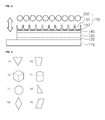
- FIG. 5 is an examplary diagram illustrating the phosphor particles of the light-emitting device according to the embodiments of the present invention.
- a chromaticity, light-emitting properties, light efficiency of the light-emitting device 100 can be adjusted by varying the size and shape of the phosphor particles 200. Therefore, the phosphor particles 200 having various sizes and shapes can be applied according to the properties of the applied phosphor, a design requirement of the light-emitting device 100, and the like.
- FIG. 5A illustrates the phosphor particles, in which its cross-section is an equilateral triangle
- FIG. 5B illustrates the phosphor having a regular hexahedron shape
- FIG. 5C illustrates the phosphor particles, in which its cross-section is an octahedron
- FIG. 5D illustrates the phosphor particles, in which its cross-section is a rhombohedra shape
- FIG. 5E illustrates the phosphor particles, in which its cross-section is a trapezoidal
- FIG. 5F illustrates the phosphor particles, in which its cross-section is a cylindrical
- FIG. 5G illustrates the phosphor particles, in which its cross-section is a right-angled triangle
- FIG. 5H illustrates the phosphor particles, in which its cross-section is a parallelogram.
- the phosphor particles can be formed as various polygonal shapes, such as a polyhedron, horn, column, etc, and will not be limited thereto, can employ the phosphor particles having various shapes, such as regular truncated pyramid shape, spherical shape, and the like.
- FiG. 6 is a perspective view illustrating the light-emitting device according to another embodiment of the present invention.
- the light-emitting device includes a metal layer 510, the first conductive semiconductor layer 520 formed on the metal layer 510, the active layer 530 formed on the first conductive semiconductor layer 520, the second conductive semiconductor layer 540 formed on the active layer 530, and the phosphor layer 550 formed on the second conductive semiconductor layer 540.
- the metal layer 510 can be made of at least one of Al, Ag, Pd, Rh, Pt, and the like, and alloys thereof.
- the first conductive semiconductor layer 520 can be implemented as the p-type semiconductor layer doped with the first conductive dopant on the metal layer 510.
- the second conductive semiconductor layer 540 can be made of any one of compound semiconductors, such as GaN, InN, AIN, InGaN, AIGaN, InAlGaN, AllnN, AlGaAs, InGaAs, AllnGaAs, GaP, AIGaP, InGaP, AllnGaP, InP, and the like.
- the second conductive dopant may include p-type dopant such as Mg, Zn, Ca, Sr, Ba, and the like.
- the active layer 530 is formed as the single quantum well or multi quantum well (MQW) structure on the first conductive semiconductor layer 520.
- the active layer 530 can emit the chromatic light (for example: blue, green, red, etc) or the ultraviolet light.
- Forming the active layer 530 can be available to use InGaN/GaN, AIGaN/GaN, or InAlGaN/GaN, GaAs/AlGaAs (InGaAs), GaP/AlGaP(InGaP), and the like, and can adjust the wavelengths of light emitted according to the band gap energy of the material that forms the well layer or barrier layer.
- InGaN well layer/GaN barrier layer can be formed as one period.
- the second conductive semiconductor layer 540 can be implemented as the n-type semiconductor doped with the second conductive dopant on the active layer 530.
- the first conductive semiconductor layer 520 can be made of any one of compound semiconductors, such as GaN, InN, AIN, InGaN, AIGaN, InAlGaN, AllnN, AlGaAs, InGaAs, AllnGaAs, GaP, AIGaP, InGaP, AllnGaP, InP, and the like.
- the first conductive dopant may include n-type dopant such as Si, Ge, Sn, Se, Te.
- the phosphor layer 550 can be formed on the second conductive semiconductor layer 540.
- the phosphor layer 550 can be formed as an uniformly distributed and fixed phosphor that is a particle.
- the plurality of the cavities 555 is formed on the second conductive semiconductor layer 540 for fixing the phosphor.
- the phosphor particles 250 have a shape corresponding to the shape of the cavities 555, and form the phosphor layer 550 by inserting and fixing in the cavities 555.
- FIG. 7 is a phase diagram for manufacturing the light-emitting device 500 according to other embodiment of the present invention, and illustrates a formation phase of the phosphor layer 550 of FIG. 6 .
- the phosphor receiving member 552 having the plurality of the cavities 555 in which its cross-section is an octagon is formed on the second conductive semiconductor layer 540.
- the cavities 555 having the octagon cross-section can be formed at a uniform distance from one another by employing Reactive Ion Etching, Wet Etching, Nano Imprinting, and the like.
- the phosphor particles 250 are polyhedron particles having the octagon cross-section, and can be provided as the hardened type of the resin and the phosphor.
- Each cavity 555 receives the phosphor particles 250 by applying the phosphor particles 250 to the phosphor receiving member 552 having the cavities 555. In this case, the remained phosphor particles that are not received in the cavities can be collected and can be re-used.
- the phosphor layer 550 can be formed on the second conductive semiconductor layer 540 by fixing using the resin or hardening itself.
- size and arrangement distance of the phosphor particles can be controlled, so that the chromaticity can be easily and precisely adjusted, and the chromatic distribution can be narrowed.
- the waste of the phosphor material upon processing can be prevented by employing as the shape of the phosphor particles 250 of the phosphor.
- the light-emitting efficiency can be improved by forming a photonic crystal type when forming the cavities 155.
Abstract
Description
- The embodiment relates to a light emitting device and a method for manufacturing the same.
- A light-emitting device (LED) is a semiconductor light-emitting device that transforms current into a light. Recently, the use of the light-emitting device has been increasing as a source of light for display, a source of light for automobile and a source of light for lighting due to gradually increasing of a luminance of LED.
- Recently, a high power light-emitting chip available for implementing full colors by producing a short wavelength light, such as blue or green has been developed. To this end, the light-emitting diode having various colors can be effective in combinations, and a light-emitting diode emitting a white light can be implemented by absorbing a part of light outputted from the light-emitting chip and applying a phosphor outputting different wavelengths with the wavelengths of light on the light-emitting chip.
- The embodiment is to provide a light-emitting device and a method for manufacturing the same that can easily and precisely control a distribution position and distribution degree of a phosphor on the light-emitting device and prevents a waste of the phosphor materials upon processing.
- According to one aspect of the embodiment, there is provided a light-emitting device and a method for manufacturing the same that can improve light efficiency on a surface of the light-emitting device chip, and can remove air layer obstructing a total reflection.
- A light-emitting device according to an exemplary embodiment of the present invention includes: a first conductive semiconductor layer; an active layer formed on the first conductive semiconductor layer; a second conductive semiconductor layer formed on the active layer; and a phosphor layer formed on the second conductive semiconductor layer, in which the phosphor layer includes a phosphor receiving member having a plurality of cavities and phosphor particles fixed in the cavities.
- A method for manufacturing the light-emitting device according to another exemplary embodiment of the present invention includes: forming the first conductive semiconductor layer on the substrate; forming the active layer on the first conductive semiconductor layer; forming the second conductive semiconductor layer on the active layer; forming the phosphor receiving member having the plurality of the cavities on the second conductive semiconductor layer; and the phosphor layer by fixing the phosphor particles on the plurality of the cavities of the phosphor receiving member.
- According to the embodiments, there is provided the light-emitting device and the method for manufacturing the same that can easily and precisely control the distribution position and distribution degree of the phosphor on the light-emitting device and prevents a waste of the phosphor materials upon processing.
- In addition, according to one aspect of the embodiment, there is provided the light-emitting device and the method for manufacturing the same that has the improved light efficiency on the surface of the light-emitting device chip, and can be removed with air layer obstructing the total reflection.
-
-
FIG. 1 is a perspective diagram showing a light-emitting device according to an embodiment of the present invention; -
FIGS. 2 to FIG. 4 are diagrams of manufacturing a light-emitting device according to an embodiment of the present invention; -
FIGS. 5A to 5H are an examplary diagram illustrating the phosphor particles of the light-emitting device according to the embodiments of the embodyment;FIG. 6 is a perspective view showing a light-emitting device according to other embodiment of the present invention; and -
FIG. 7 is a diagram for manufacturing the light-emitting device according to other embodiments of the present invention. - Hereinafter, the light-emitting device and the method for manufacturing the same according to the embodiments will be described in detail with reference to the appended drawings. For the description of the embodiments, in the case of describing as forming each layer (film), portions, patterns or structures "on" or "under" substrates, each layer (film), portions, pads or patterns, "on" or "under" includes all of "directly" or "indirectly" formed things. In addition, a standard about "on" or "under" each layer will be described based on the drawings. In the drawings, a thickness or size of each layer is shown roughly, exaggeratedly, or briefly for convenience sake of the description or for a definite description. In addition, a size of each element does not reflect entirely real size.
-
FIG. 1 is a perspective diagram illustrating a light-emitting device according to an embodiment of the present invention. - As shown in
FIG. 1 , a light-emitting device 100 includes asubstrate 110, a firstconductive semiconductor layer 120 formed on thesubstrate 110; aactive layer 130 formed on the firstconductive semiconductor layer 120; a secondconductive semiconductor layer 140 formed on theactive layer 130; and aphosphor layer 150 formed on the secondconductive semiconductor layer 140. - The
substrate 110 may comprise at least one of Al2O3, SiC, Si, GaAs, GaN, ZnO, GaP, InP and Ge, and may have a conductive property. In addition, thesubstrate 110 can be also applicable to a vertical chip by removing the substrate after Epi growth. In this case, Physical Grinding, Laser Lift Off (LLO), Chemical Wet Etching, and the like can remove the substrate. - The first
conductive semiconductor layer 120 can be an n-type semiconductor layer having at least one layer doped with a first conductive dopant. The firstconductive semiconductor layer 120 can be formed with at least one of GaN, InN, AIN, InGaN, AIGaN, InAIGaN, AIInN, AIGaAs, InGaAs, AIInGaAs, GaP, AIGaP, InGaP, AllnGaP, and InP. When setting the firstconductive semiconductor layer 120 as an electron injection layer, the first conductive dopant may include n-type dopant such as Si, Ge, Sn, Se, Te. The first conductive dopant may function as the electrode contact layer hereafter. - The
active layer 130 is formed as a single quantum well or multi quantum well (MQW) structure on the firstconductive semiconductor layer 120. Theactive layer 130 can emit a chromatic light (for example: blue, green, red, etc) or an ultraviolet light. Theactive layer 130 may be formed by InGaN/GaN, AIGaN/GaN, or InAlGaN/GaN, GaAs/AlGaAs (InGaAs), GaP/AlGaP(InGaP), and the like, and can adjust a wavelengths of light emitted according to a band gap energy of a material that forms a well layer or barrier layer. For example, in the case of a blue light-emitting of 460-470nm wavelengths, InGaN well layer/GaN barrier layer can be formed as one period. - The second
conductive semiconductor layer 140 can be implemented as p-type semiconductor doped with the second conductive dopant on theactive layer 130. The secondconductive semiconductor layer 140 may include any one of compound semiconductors, such as GaN, InN, AIN, InGaN, AIGaN, InAlGaN, AllnN, AlGaAs, InGaAs, AllnGaAs, GaP, AIGaP, InGaP, AllnGaP, InP, and the like. P-type dopant such as Mg, Zn, Ca, Sr, Ba, etc. can be added to the secondconductive semiconductor layer 140. - The
phosphor layer 150 can be formed on the secondconductive semiconductor layer 140. Thephosphor layer 150 can be formed as an unifomlydistributed and fixed phosphor that is a particle. Thephosphor layer 150 includes the phosphor receiving member 152 that has the plurality of cavities 155 for fixing of the phosphor and thephosphor particles 200 fixed in the cavities 155. - The
phosphor particles 200 have a corresponding shape to the cavities 155 shape, and may be injected and fixed in the cavities 155 of the phosphor receiving member 152, thereby forming thephosphor layer 150. Therefore, the phosphor can be distributed uniformly, and the light-emitting efficiency can be improved by forming a photonic crystal type when forming the cavities 155. In addition, by forming thephosphor layer 150 to be overlapped in the light-emitting portion of the secondconductive semiconductor layer 140, there is an effect that an air layer having a different refractive index is removed, and the total reflection can be reduced, so that a color distribution can be narrowed. According to the embodiments of the present invention, the light emitted from theactive layer 130 emits to outside through the secondconductive semiconductor layer 140 and thephosphor layer 150. Therefore, the light emitted from theactive layer 130 can be converted to a light having a different wavelengths in the phosphor layer, and emit as the chromatic light or white light type having fixed colors, so that a light extraction efficiency can be improved by the photonic crystal shape of thephosphor layer 150. - Meanwhile, the description as mentioned above illustrates when positioning the
active layer 130 having the quantum well between the firstconductive semiconductor layer 120 formed as a n-type GaN that is basically made of GaN based material and the electron injection layer and the secondconductive semiconductor layer 140 formed as a p-type GaN that is a hole injection layer. However the order of layers can be changed by forming the first conductive semiconductor layer as the p-type semiconductor and the second conductive semiconductor layer as the n-type semiconductor. -
FIGS. 2 to FIG. 4 are diagrams to illustrate manufacturing the light-emitting device according to the embodiments of the present invention, and illustrate manufacturing thephosphor layer 150. - As shown in
FIG. 2 , a mixed liquid of the phosphor 320 is injected in a mold which resembles the shape of thephosphor particles 200 in order to form thephosphor particles 200. - A shape of the
phosphor particles 200 in themold 300 is aconcave portion 310, so that the mold receives the mixed liquid of the phosphor 320. Theconcave portion 310 can be formed as a spherical like shape, a polygonal shape, a conical shape, a truncated pyramidal shape, a rectangular shape, and a cylindrical shape, etc. according to the shape of thephosphor particles 200 to be formed. In addition, theconcave portion 310 can be formed as a various size from several um to at least 1mm size according to the size of thephosphor particles 200. In this case, themold 300 can be possible to be configured a type to complete thephosphor particles 200 shapes by matching each other according to the shape of thephosphor particles 200. - The mixed liquid of the phosphor 320 can be made by mixing the phosphor and resin. Various species of R. G. B. phosphor, such as silicate series, sulfide series, garnet series, nitride series, yttrium, aluminum, etc. can be selectively applied to the mixed phosphor. The resin forming the mixed liquid of the phosphor is a material available to be mixed or harden can employ various materials, such as silicone or a transparent epoxy resin, etc. The fixed solvent can be added to the mixed liquid of the phosphor and resin in order to control a viscosity.
-
FIG. 3 illustrates separating of thephosphor particles 200. - The
phosphor particles 200 according to the concave shape are formed by charging the mixed liquid of the phosphor 320 to theconcave portion 310 of themold 300, and then hardening, - The
phosphor particles 200 having a regular shape can be achieved by separating thehardened phosphor particles 200 from themold 300. Therefore, a leaking or hardening of the phosphor before use can be prevented by forming thephosphor particles 200 by preparing the mixed liquid of the phosphor 320 merely when it is needed and charging it to theconcave portion 310. -
FIG. 4 illustrates a method for manufacturing thephosphor layer 150 of the light-emitting device. - The phosphor receiving member 152 having the plurality of the cavities for fixing the
phosphor particles 200 is formed on the secondconductive semiconductor layer 140. Thephosphor layer 150 is formed on the secondconductive semiconductor layer 140 by applying thephosphor particles 200 in the phosphor receiving member 152 having the cavities 155 and hardening. Thephosphor particles 200 received in the cavities 155 can be fixed by using the resin, or can be fixed through the hardening process. In this case, thephosphor particles 200 remained after being received in the cavities 155 among thephosphor particles 200 applied in the phosphor receiving member 152 can be reused, so that the waste of the phosphor materials can be prevented. - The cavities 155 formed in the phosphor receiving member 152 can be employed with Reactive Ion Etching (RIE) by using a photo resistor, Nano Imprinting, Tape Adhesive way, etc. In this case, the shape of the cavities 155 can be formed to match with the shape of the
phosphor particles 200, and the light-emitting properties of the light-emitting device can be adjusted by controlling the arrangement way, arrangement distance, and the like. Thephosphor particles 200 are received in the cavities 155 by applying thephosphor particles 200 in the phosphor receiving member 152 having the cavities 155. The light can be distributed uniformly by inserting one of the phosphor particles 200 in each of cavities 155. However, it may also be possible that one cavity receives more that onephosphor particle 200 according to the cavities 155 and the sizes or shapes of thephosphor particles 200. -
FIG. 5 is an examplary diagram illustrating the phosphor particles of the light-emitting device according to the embodiments of the present invention. - A chromaticity, light-emitting properties, light efficiency of the light-emitting
device 100 can be adjusted by varying the size and shape of thephosphor particles 200. Therefore, thephosphor particles 200 having various sizes and shapes can be applied according to the properties of the applied phosphor, a design requirement of the light-emittingdevice 100, and the like. -
FIG. 5A illustrates the phosphor particles, in which its cross-section is an equilateral triangle,FIG. 5B illustrates the phosphor having a regular hexahedron shape.FIG. 5C illustrates the phosphor particles, in which its cross-section is an octahedron, andFIG. 5D illustrates the phosphor particles, in which its cross-section is a rhombohedra shape.FIG. 5E illustrates the phosphor particles, in which its cross-section is a trapezoidal, andFIG. 5F illustrates the phosphor particles, in which its cross-section is a cylindrical.FIG. 5G illustrates the phosphor particles, in which its cross-section is a right-angled triangle, andFIG. 5H illustrates the phosphor particles, in which its cross-section is a parallelogram. - As shown in
FIGS. 5A to 5H , the phosphor particles can be formed as various polygonal shapes, such as a polyhedron, horn, column, etc, and will not be limited thereto, can employ the phosphor particles having various shapes, such as regular truncated pyramid shape, spherical shape, and the like. -
FiG. 6 is a perspective view illustrating the light-emitting device according to another embodiment of the present invention. - The light-emitting device includes a
metal layer 510, the firstconductive semiconductor layer 520 formed on themetal layer 510, theactive layer 530 formed on the firstconductive semiconductor layer 520, the secondconductive semiconductor layer 540 formed on theactive layer 530, and thephosphor layer 550 formed on the secondconductive semiconductor layer 540. - The
metal layer 510 can be made of at least one of Al, Ag, Pd, Rh, Pt, and the like, and alloys thereof. - The first
conductive semiconductor layer 520 can be implemented as the p-type semiconductor layer doped with the first conductive dopant on themetal layer 510. The secondconductive semiconductor layer 540 can be made of any one of compound semiconductors, such as GaN, InN, AIN, InGaN, AIGaN, InAlGaN, AllnN, AlGaAs, InGaAs, AllnGaAs, GaP, AIGaP, InGaP, AllnGaP, InP, and the like. - The second conductive dopant may include p-type dopant such as Mg, Zn, Ca, Sr, Ba, and the like.
- The
active layer 530 is formed as the single quantum well or multi quantum well (MQW) structure on the firstconductive semiconductor layer 520. Theactive layer 530 can emit the chromatic light (for example: blue, green, red, etc) or the ultraviolet light. Forming theactive layer 530 can be available to use InGaN/GaN, AIGaN/GaN, or InAlGaN/GaN, GaAs/AlGaAs (InGaAs), GaP/AlGaP(InGaP), and the like, and can adjust the wavelengths of light emitted according to the band gap energy of the material that forms the well layer or barrier layer. For example, in the case of the blue light-emitting of 460-470nm wavelengths, InGaN well layer/GaN barrier layer can be formed as one period. - The second
conductive semiconductor layer 540 can be implemented as the n-type semiconductor doped with the second conductive dopant on theactive layer 530. The firstconductive semiconductor layer 520 can be made of any one of compound semiconductors, such as GaN, InN, AIN, InGaN, AIGaN, InAlGaN, AllnN, AlGaAs, InGaAs, AllnGaAs, GaP, AIGaP, InGaP, AllnGaP, InP, and the like. - When setting the first
conductive semiconductor layer 120 as an electron injection layer, the first conductive dopant may include n-type dopant such as Si, Ge, Sn, Se, Te. - The
phosphor layer 550 can be formed on the secondconductive semiconductor layer 540. - The
phosphor layer 550 can be formed as an uniformly distributed and fixed phosphor that is a particle. The plurality of the cavities 555 is formed on the secondconductive semiconductor layer 540 for fixing the phosphor. Thephosphor particles 250 have a shape corresponding to the shape of the cavities 555, and form thephosphor layer 550 by inserting and fixing in the cavities 555. -
FIG. 7 is a phase diagram for manufacturing the light-emittingdevice 500 according to other embodiment of the present invention, and illustrates a formation phase of thephosphor layer 550 ofFIG. 6 . - As shown in
FIG. 7 , thephosphor receiving member 552 having the plurality of the cavities 555 in which its cross-section is an octagon is formed on the secondconductive semiconductor layer 540. The cavities 555 having the octagon cross-section can be formed at a uniform distance from one another by employing Reactive Ion Etching, Wet Etching, Nano Imprinting, and the like. - The
phosphor particles 250 are polyhedron particles having the octagon cross-section, and can be provided as the hardened type of the resin and the phosphor. - Each cavity 555 receives the
phosphor particles 250 by applying thephosphor particles 250 to thephosphor receiving member 552 having the cavities 555. In this case, the remained phosphor particles that are not received in the cavities can be collected and can be re-used. - When inserting the
phosphor particles 250 to the cavities 555, thephosphor layer 550 can be formed on the secondconductive semiconductor layer 540 by fixing using the resin or hardening itself. - According to the embodiments as mentioned above, size and arrangement distance of the phosphor particles can be controlled, so that the chromaticity can be easily and precisely adjusted, and the chromatic distribution can be narrowed. In addition, the waste of the phosphor material upon processing can be prevented by employing as the shape of the
phosphor particles 250 of the phosphor. And the light-emitting efficiency can be improved by forming a photonic crystal type when forming the cavities 155. - Features, structures, effect, and the like as mentioned in the embodiment as mentioned above are included in at least one embodiment of the present invention, and will not be limited thereto. In addition, Features, structures, effect, and the like as illustrated in each embodiment of the present invention can be combined and modified by those skilled in the prior arts field. Therefore, it should be understood that the contents related to the combinations and modifications are included in the scope of the present invention.
- In addition, the embodiments were described as mentioned above, but they are only examples, and cannot be limited thereto. If the person have skills about the prior art field, they can modify and be applicable within the essential scope of the present invention. For example, each element that is described in the embodiments can be modified and be performed. And it should be understood that the difference related to the modifications and the applications is included in the scope of the present invention as defined in the appended claims.
Claims (15)
- A light-emitting device comprising:a first conductive semiconductor layer;an active layer formed on the first conductive semiconductor layer;a second conductive semiconductor layer formed on the active layer; anda phosphor layer formed on the second conductive semiconductor layer, wherein the phosphor layer includes a plurality of cavities and a plurality of phosphor particles, and wherein each of the plurality of phosphor particles is positioned in a corresponding one of the plurality of cavities.
- The light-emitting device according to claim 1, wherein the plurality of cavities and the plurality of phosphor particles are formed from the same phosphor material.
- The light-emitting device according to claim 1, wherein the phosphor layer is formed directly on the second conductive semiconductor layer.
- The light-emitting device according to claim 1, wherein each of the plurality of phosphor particles is fixed in a corresponding one of the plurality of cavities.
- The light-emitting device according to claim 4, wherein the plurality of phosphor particles are covered with a resin material.
- The light-emitting device according to claim 1, wherein each of the plurality of cavities and each of the plurality of phosphor particles are spherical in shape.
- The light-emitting device according to claim 1, wherein the plurality of cavities are positioned a uniform distance apart from one another.
- The light-emitting device according to claim 1, wherein the width of each of the plurality of cavities is greater than 10um.
- The light-emitting device according to claim 1, wherein each of the plurality of phosphor particles and each of the plurality of cavities are formed in one of a spherical like shape, a polygonal shape, a conical shape, a truncated pyramidal shape, a rectangular shape, and a cylindrical shape.
- The light-emitting device according to claim 1, wherein the plurality of phosphor particles include a phosphor material and a resin.
- A method of manufacturing a light-emitting device comprising:forming a first conductive semiconductor layer on a substrate;forming an active layer on the first conductive semiconductor layer;forming a second conductive semiconductor layer on the active layer; andforming a phosphor layer on the second conductive semiconductor layer, wherein the phosphor layer includes a plurality of cavities and a plurality of phosphor particles, and wherein each of the plurality of phosphor particles is positioned in a corresponding one of the plurality of cavities.
- The method of manufacturing the light-emitting device according to claim 11, wherein forming the phosphor layer comprises:fixing each of the plurality of phosphor particles in a corresponding one of the plurality of cavities.
- The method of manufacturing the light-emitting device according to claim 12, wherein forming the phosphor layer further comprises:covering the plurality of phosphor particles with a resin material.
- The method of manufacturing the light-emitting device according to claim 11, wherein forming the phosphor layer comprises:forming the plurality of cavities using at least one of Reactive Ion Etching (RIE), Wet Etching, Nano Imprinting, and Tape adhesive way.
- The method of manufacturing the light-emitting device according to claim 11 further comprises forming the plurality of phosphor particles, and wherein forming the plurality of phosphor particles comprises:mixing phosphor and resin;injecting the phosphor and resin mixture in a mold to form the plurality of phosphor particles each having a desired shape;allowing the phosphor and resin mixture in the mold to harden; andseparating the hardened phosphor particles from the mold.
Applications Claiming Priority (1)
| Application Number | Priority Date | Filing Date | Title |
|---|---|---|---|
| KR1020090109369A KR101020998B1 (en) | 2009-11-12 | 2009-11-12 | Light emitting device and method for fabricating the same |
Publications (3)
| Publication Number | Publication Date |
|---|---|
| EP2323185A2 true EP2323185A2 (en) | 2011-05-18 |
| EP2323185A3 EP2323185A3 (en) | 2014-02-26 |
| EP2323185B1 EP2323185B1 (en) | 2018-02-14 |
Family
ID=43480676
Family Applications (1)
| Application Number | Title | Priority Date | Filing Date |
|---|---|---|---|
| EP10177748.0A Active EP2323185B1 (en) | 2009-11-12 | 2010-09-20 | Light emitting device and method for manufacturing the same |
Country Status (6)
| Country | Link |
|---|---|
| US (1) | US8405095B2 (en) |
| EP (1) | EP2323185B1 (en) |
| JP (1) | JP5619546B2 (en) |
| KR (1) | KR101020998B1 (en) |
| CN (1) | CN102088057B (en) |
| TW (1) | TWI497774B (en) |
Cited By (6)
| Publication number | Priority date | Publication date | Assignee | Title |
|---|---|---|---|---|
| WO2020229576A3 (en) * | 2019-05-14 | 2021-01-07 | Osram Opto Semiconductors Gmbh | Illumination unit, method for producing an illumination unit, converter element for an optoelectronic component, radiation source including an led and a converter element, outcoupling structure, and optoelectronic device |
| US11156759B2 (en) | 2019-01-29 | 2021-10-26 | Osram Opto Semiconductors Gmbh | μ-LED, μ-LED device, display and method for the same |
| US11271143B2 (en) | 2019-01-29 | 2022-03-08 | Osram Opto Semiconductors Gmbh | μ-LED, μ-LED device, display and method for the same |
| US11302248B2 (en) | 2019-01-29 | 2022-04-12 | Osram Opto Semiconductors Gmbh | U-led, u-led device, display and method for the same |
| US11538852B2 (en) | 2019-04-23 | 2022-12-27 | Osram Opto Semiconductors Gmbh | μ-LED, μ-LED device, display and method for the same |
| US11610868B2 (en) | 2019-01-29 | 2023-03-21 | Osram Opto Semiconductors Gmbh | μ-LED, μ-LED device, display and method for the same |
Families Citing this family (7)
| Publication number | Priority date | Publication date | Assignee | Title |
|---|---|---|---|---|
| KR101726807B1 (en) * | 2010-11-01 | 2017-04-14 | 삼성전자주식회사 | Light Emitting Device |
| JP5864367B2 (en) * | 2011-06-16 | 2016-02-17 | 日東電工株式会社 | Fluorescent adhesive sheet, light-emitting diode element with phosphor layer, light-emitting diode device, and manufacturing method thereof |
| CN103258942A (en) * | 2012-02-20 | 2013-08-21 | 联胜(中国)科技有限公司 | Optical structural body and light-emitting device |
| US9193645B2 (en) | 2012-08-31 | 2015-11-24 | Exxonmobil Chemical Patents Inc. | Xylene isomerization process and catalyst therefor |
| CN103137840A (en) * | 2013-02-27 | 2013-06-05 | 中国科学院半导体研究所 | Light emitting diode of white light and manufacturing method |
| JP6307703B2 (en) * | 2013-05-31 | 2018-04-11 | パナソニックIpマネジメント株式会社 | Wavelength converting element, light emitting device including wavelength converting element, vehicle including light emitting device, and method of manufacturing wavelength converting element |
| US20180287020A1 (en) * | 2015-04-27 | 2018-10-04 | Lumimicro Corp. Ltd. | Light-emitting diode device, manufacturing method therefor, and mold used therefor |
Citations (2)
| Publication number | Priority date | Publication date | Assignee | Title |
|---|---|---|---|---|
| JP2003243726A (en) * | 2001-12-14 | 2003-08-29 | Nichia Chem Ind Ltd | Light emitting apparatus and manufacturing method therefor |
| WO2009020547A2 (en) * | 2007-08-07 | 2009-02-12 | Cree, Inc. | Semiconductor light emitting diodes with applied wavelength materials and methods of forming the same |
Family Cites Families (18)
| Publication number | Priority date | Publication date | Assignee | Title |
|---|---|---|---|---|
| TW383508B (en) * | 1996-07-29 | 2000-03-01 | Nichia Kagaku Kogyo Kk | Light emitting device and display |
| JP4822482B2 (en) | 2001-05-23 | 2011-11-24 | シチズン電子株式会社 | Light emitting diode and manufacturing method thereof |
| JP4124056B2 (en) | 2003-08-14 | 2008-07-23 | 昭栄化学工業株式会社 | Method for producing phosphor powder |
| US7675075B2 (en) * | 2003-08-28 | 2010-03-09 | Panasonic Corporation | Semiconductor light emitting device, light emitting module, lighting apparatus, display element and manufacturing method of semiconductor light emitting device |
| US7597814B2 (en) | 2004-03-23 | 2009-10-06 | Hewlett Packard Development Company, L.P. | Structure formed with template having nanoscale features |
| TW200614548A (en) * | 2004-07-09 | 2006-05-01 | Matsushita Electric Ind Co Ltd | Light-emitting device |
| US7352011B2 (en) * | 2004-11-15 | 2008-04-01 | Philips Lumileds Lighting Company, Llc | Wide emitting lens for LED useful for backlighting |
| JP2007059418A (en) | 2005-08-22 | 2007-03-08 | Showa Denko Kk | Nitride gallium based compound semiconductor light-emitting element |
| JP4984824B2 (en) * | 2006-10-26 | 2012-07-25 | 豊田合成株式会社 | Light emitting device |
| JP5152687B2 (en) | 2006-12-07 | 2013-02-27 | 日本電気硝子株式会社 | Luminescent color conversion material |
| US7514282B2 (en) * | 2007-01-04 | 2009-04-07 | Sharp Laboratories Of America, Inc. | Patterned silicon submicron tubes |
| KR101259122B1 (en) * | 2007-01-26 | 2013-04-26 | 엘지전자 주식회사 | Light emitting device having vertical topology and method for manufacturing the same |
| JP5229770B2 (en) * | 2007-03-22 | 2013-07-03 | 株式会社フジクラ | Sialon phosphor |
| KR20090002835A (en) * | 2007-07-04 | 2009-01-09 | 엘지전자 주식회사 | Nitride light emitting device and method of making the same |
| KR100936001B1 (en) * | 2007-12-17 | 2010-01-08 | 삼성전기주식회사 | Nitride semiconductor light emitting device and manufacturing method thereof |
| JP2009200172A (en) | 2008-02-20 | 2009-09-03 | Sharp Corp | Manufacturing method of optical semiconductor device, and manufacturing device of optical semiconductor device |
| JP2009260053A (en) | 2008-04-17 | 2009-11-05 | Nichia Corp | Light emitting device |
| US20100207511A1 (en) * | 2009-02-19 | 2010-08-19 | Mitsunori Harada | Semiconductor light emitting device |
-
2009
- 2009-11-12 KR KR1020090109369A patent/KR101020998B1/en active IP Right Grant
-
2010
- 2010-08-30 US US12/871,397 patent/US8405095B2/en active Active
- 2010-09-10 TW TW099130591A patent/TWI497774B/en active
- 2010-09-15 JP JP2010206939A patent/JP5619546B2/en active Active
- 2010-09-20 EP EP10177748.0A patent/EP2323185B1/en active Active
- 2010-11-05 CN CN201010538785.XA patent/CN102088057B/en not_active Expired - Fee Related
Patent Citations (2)
| Publication number | Priority date | Publication date | Assignee | Title |
|---|---|---|---|---|
| JP2003243726A (en) * | 2001-12-14 | 2003-08-29 | Nichia Chem Ind Ltd | Light emitting apparatus and manufacturing method therefor |
| WO2009020547A2 (en) * | 2007-08-07 | 2009-02-12 | Cree, Inc. | Semiconductor light emitting diodes with applied wavelength materials and methods of forming the same |
Cited By (9)
| Publication number | Priority date | Publication date | Assignee | Title |
|---|---|---|---|---|
| US11156759B2 (en) | 2019-01-29 | 2021-10-26 | Osram Opto Semiconductors Gmbh | μ-LED, μ-LED device, display and method for the same |
| US11271143B2 (en) | 2019-01-29 | 2022-03-08 | Osram Opto Semiconductors Gmbh | μ-LED, μ-LED device, display and method for the same |
| US11302248B2 (en) | 2019-01-29 | 2022-04-12 | Osram Opto Semiconductors Gmbh | U-led, u-led device, display and method for the same |
| US11480723B2 (en) | 2019-01-29 | 2022-10-25 | Osram Opto Semiconductors Gmbh | μ-LED, μ-LED device, display and method for the same |
| US11513275B2 (en) | 2019-01-29 | 2022-11-29 | Osram Opto Semiconductors Gmbh | μ-LED, μ-LED device, display and method for the same |
| US11610868B2 (en) | 2019-01-29 | 2023-03-21 | Osram Opto Semiconductors Gmbh | μ-LED, μ-LED device, display and method for the same |
| US11764339B2 (en) | 2019-01-29 | 2023-09-19 | Osram Opto Semiconductors Gmbh | μ-LED, μ-LED device, display and method for the same |
| US11538852B2 (en) | 2019-04-23 | 2022-12-27 | Osram Opto Semiconductors Gmbh | μ-LED, μ-LED device, display and method for the same |
| WO2020229576A3 (en) * | 2019-05-14 | 2021-01-07 | Osram Opto Semiconductors Gmbh | Illumination unit, method for producing an illumination unit, converter element for an optoelectronic component, radiation source including an led and a converter element, outcoupling structure, and optoelectronic device |
Also Published As
| Publication number | Publication date |
|---|---|
| TWI497774B (en) | 2015-08-21 |
| EP2323185A3 (en) | 2014-02-26 |
| JP2011109070A (en) | 2011-06-02 |
| EP2323185B1 (en) | 2018-02-14 |
| TW201119094A (en) | 2011-06-01 |
| US20110108867A1 (en) | 2011-05-12 |
| US8405095B2 (en) | 2013-03-26 |
| CN102088057A (en) | 2011-06-08 |
| JP5619546B2 (en) | 2014-11-05 |
| KR101020998B1 (en) | 2011-03-09 |
| CN102088057B (en) | 2016-05-04 |
Similar Documents
| Publication | Publication Date | Title |
|---|---|---|
| US8405095B2 (en) | Light-emitting device and method for manufacturing the same | |
| EP2448017B1 (en) | Semiconductor light emitting device | |
| US11171267B2 (en) | Process for fabricating an optoelectronic device including photoluminescent pads of photoresist | |
| US8835202B2 (en) | Structure and method for LED with phosphor coating | |
| US8674339B2 (en) | Light-emitting devices and methods of manufacturing the same | |
| US20150060917A1 (en) | Light emitting device with wavelength converting side coat | |
| JP5994628B2 (en) | LIGHT EMITTING DEVICE MANUFACTURING METHOD AND SPRAY COATING DEVICE | |
| CN114050210B (en) | Light emitting diode chip, preparation method thereof and display device | |
| KR20120050281A (en) | Light emitting device and manufacturing method of the same | |
| KR20180078940A (en) | Light emitting diode chip and manufacturing method thereof | |
| US20150233551A1 (en) | Method of manufacturing light source module and method of manufacturing lighting device | |
| US20190157518A1 (en) | Method of manufacturing light emitting device | |
| JP6626536B2 (en) | How to apply materials to surfaces | |
| US11600751B2 (en) | Light-emitting semiconductor component and method for producing a light-emitting semiconductor component | |
| US8455900B2 (en) | Semiconductor light-emitting device having an optical member, and method of manufacturing the same | |
| KR101646256B1 (en) | Lgiht emitting device | |
| JP6974702B2 (en) | Manufacturing method of semiconductor light emitting device | |
| CN114628550A (en) | Method for manufacturing light emitting device and method for manufacturing light emitting module | |
| KR20120116814A (en) | Light emitting device and method for fabricating the same |
Legal Events
| Date | Code | Title | Description |
|---|---|---|---|
| PUAI | Public reference made under article 153(3) epc to a published international application that has entered the european phase |
Free format text: ORIGINAL CODE: 0009012 |
|
| 17P | Request for examination filed |
Effective date: 20100920 |
|
| AK | Designated contracting states |
Kind code of ref document: A2 Designated state(s): AL AT BE BG CH CY CZ DE DK EE ES FI FR GB GR HR HU IE IS IT LI LT LU LV MC MK MT NL NO PL PT RO SE SI SK SM TR |
|
| AX | Request for extension of the european patent |
Extension state: BA ME RS |
|
| PUAL | Search report despatched |
Free format text: ORIGINAL CODE: 0009013 |
|
| AK | Designated contracting states |
Kind code of ref document: A3 Designated state(s): AL AT BE BG CH CY CZ DE DK EE ES FI FR GB GR HR HU IE IS IT LI LT LU LV MC MK MT NL NO PL PT RO SE SI SK SM TR |
|
| AX | Request for extension of the european patent |
Extension state: BA ME RS |
|
| RIC1 | Information provided on ipc code assigned before grant |
Ipc: H01L 33/50 20100101AFI20140121BHEP |
|
| RAP1 | Party data changed (applicant data changed or rights of an application transferred) |
Owner name: LG INNOTEK CO., LTD. |
|
| RBV | Designated contracting states (corrected) |
Designated state(s): AL AT BE BG CH CY CZ DE DK EE ES FI FR GB GR HR HU IE IS IT LI LT LU LV MC MK MT NL NO PL PT RO SE SI SK SM TR |
|
| 17Q | First examination report despatched |
Effective date: 20151111 |
|
| RAP1 | Party data changed (applicant data changed or rights of an application transferred) |
Owner name: LG INNOTEK CO., LTD. |
|
| GRAP | Despatch of communication of intention to grant a patent |
Free format text: ORIGINAL CODE: EPIDOSNIGR1 |
|
| INTG | Intention to grant announced |
Effective date: 20170830 |
|
| GRAS | Grant fee paid |
Free format text: ORIGINAL CODE: EPIDOSNIGR3 |
|
| GRAA | (expected) grant |
Free format text: ORIGINAL CODE: 0009210 |
|
| AK | Designated contracting states |
Kind code of ref document: B1 Designated state(s): AL AT BE BG CH CY CZ DE DK EE ES FI FR GB GR HR HU IE IS IT LI LT LU LV MC MK MT NL NO PL PT RO SE SI SK SM TR |
|
| REG | Reference to a national code |
Ref country code: GB Ref legal event code: FG4D |
|
| REG | Reference to a national code |
Ref country code: CH Ref legal event code: EP |
|
| REG | Reference to a national code |
Ref country code: IE Ref legal event code: FG4D |
|
| REG | Reference to a national code |
Ref country code: AT Ref legal event code: REF Ref document number: 970387 Country of ref document: AT Kind code of ref document: T Effective date: 20180315 Ref country code: DE Ref legal event code: R096 Ref document number: 602010048457 Country of ref document: DE |
|
| REG | Reference to a national code |
Ref country code: NL Ref legal event code: FP |
|
| REG | Reference to a national code |
Ref country code: AT Ref legal event code: MK05 Ref document number: 970387 Country of ref document: AT Kind code of ref document: T Effective date: 20180214 |
|
| PG25 | Lapsed in a contracting state [announced via postgrant information from national office to epo] |
Ref country code: NO Free format text: LAPSE BECAUSE OF FAILURE TO SUBMIT A TRANSLATION OF THE DESCRIPTION OR TO PAY THE FEE WITHIN THE PRESCRIBED TIME-LIMIT Effective date: 20180514 Ref country code: FI Free format text: LAPSE BECAUSE OF FAILURE TO SUBMIT A TRANSLATION OF THE DESCRIPTION OR TO PAY THE FEE WITHIN THE PRESCRIBED TIME-LIMIT Effective date: 20180214 Ref country code: LT Free format text: LAPSE BECAUSE OF FAILURE TO SUBMIT A TRANSLATION OF THE DESCRIPTION OR TO PAY THE FEE WITHIN THE PRESCRIBED TIME-LIMIT Effective date: 20180214 Ref country code: HR Free format text: LAPSE BECAUSE OF FAILURE TO SUBMIT A TRANSLATION OF THE DESCRIPTION OR TO PAY THE FEE WITHIN THE PRESCRIBED TIME-LIMIT Effective date: 20180214 Ref country code: CY Free format text: LAPSE BECAUSE OF FAILURE TO SUBMIT A TRANSLATION OF THE DESCRIPTION OR TO PAY THE FEE WITHIN THE PRESCRIBED TIME-LIMIT Effective date: 20180214 Ref country code: ES Free format text: LAPSE BECAUSE OF FAILURE TO SUBMIT A TRANSLATION OF THE DESCRIPTION OR TO PAY THE FEE WITHIN THE PRESCRIBED TIME-LIMIT Effective date: 20180214 |
|
| PG25 | Lapsed in a contracting state [announced via postgrant information from national office to epo] |
Ref country code: LV Free format text: LAPSE BECAUSE OF FAILURE TO SUBMIT A TRANSLATION OF THE DESCRIPTION OR TO PAY THE FEE WITHIN THE PRESCRIBED TIME-LIMIT Effective date: 20180214 Ref country code: SE Free format text: LAPSE BECAUSE OF FAILURE TO SUBMIT A TRANSLATION OF THE DESCRIPTION OR TO PAY THE FEE WITHIN THE PRESCRIBED TIME-LIMIT Effective date: 20180214 Ref country code: AT Free format text: LAPSE BECAUSE OF FAILURE TO SUBMIT A TRANSLATION OF THE DESCRIPTION OR TO PAY THE FEE WITHIN THE PRESCRIBED TIME-LIMIT Effective date: 20180214 Ref country code: GR Free format text: LAPSE BECAUSE OF FAILURE TO SUBMIT A TRANSLATION OF THE DESCRIPTION OR TO PAY THE FEE WITHIN THE PRESCRIBED TIME-LIMIT Effective date: 20180515 Ref country code: BG Free format text: LAPSE BECAUSE OF FAILURE TO SUBMIT A TRANSLATION OF THE DESCRIPTION OR TO PAY THE FEE WITHIN THE PRESCRIBED TIME-LIMIT Effective date: 20180514 |
|
| PG25 | Lapsed in a contracting state [announced via postgrant information from national office to epo] |
Ref country code: IT Free format text: LAPSE BECAUSE OF FAILURE TO SUBMIT A TRANSLATION OF THE DESCRIPTION OR TO PAY THE FEE WITHIN THE PRESCRIBED TIME-LIMIT Effective date: 20180214 Ref country code: AL Free format text: LAPSE BECAUSE OF FAILURE TO SUBMIT A TRANSLATION OF THE DESCRIPTION OR TO PAY THE FEE WITHIN THE PRESCRIBED TIME-LIMIT Effective date: 20180214 Ref country code: RO Free format text: LAPSE BECAUSE OF FAILURE TO SUBMIT A TRANSLATION OF THE DESCRIPTION OR TO PAY THE FEE WITHIN THE PRESCRIBED TIME-LIMIT Effective date: 20180214 Ref country code: PL Free format text: LAPSE BECAUSE OF FAILURE TO SUBMIT A TRANSLATION OF THE DESCRIPTION OR TO PAY THE FEE WITHIN THE PRESCRIBED TIME-LIMIT Effective date: 20180214 Ref country code: EE Free format text: LAPSE BECAUSE OF FAILURE TO SUBMIT A TRANSLATION OF THE DESCRIPTION OR TO PAY THE FEE WITHIN THE PRESCRIBED TIME-LIMIT Effective date: 20180214 |
|
| REG | Reference to a national code |
Ref country code: DE Ref legal event code: R097 Ref document number: 602010048457 Country of ref document: DE |
|
| PG25 | Lapsed in a contracting state [announced via postgrant information from national office to epo] |
Ref country code: SK Free format text: LAPSE BECAUSE OF FAILURE TO SUBMIT A TRANSLATION OF THE DESCRIPTION OR TO PAY THE FEE WITHIN THE PRESCRIBED TIME-LIMIT Effective date: 20180214 Ref country code: SM Free format text: LAPSE BECAUSE OF FAILURE TO SUBMIT A TRANSLATION OF THE DESCRIPTION OR TO PAY THE FEE WITHIN THE PRESCRIBED TIME-LIMIT Effective date: 20180214 Ref country code: DK Free format text: LAPSE BECAUSE OF FAILURE TO SUBMIT A TRANSLATION OF THE DESCRIPTION OR TO PAY THE FEE WITHIN THE PRESCRIBED TIME-LIMIT Effective date: 20180214 Ref country code: CZ Free format text: LAPSE BECAUSE OF FAILURE TO SUBMIT A TRANSLATION OF THE DESCRIPTION OR TO PAY THE FEE WITHIN THE PRESCRIBED TIME-LIMIT Effective date: 20180214 |
|
| PLBE | No opposition filed within time limit |
Free format text: ORIGINAL CODE: 0009261 |
|
| STAA | Information on the status of an ep patent application or granted ep patent |
Free format text: STATUS: NO OPPOSITION FILED WITHIN TIME LIMIT |
|
| 26N | No opposition filed |
Effective date: 20181115 |
|
| PG25 | Lapsed in a contracting state [announced via postgrant information from national office to epo] |
Ref country code: SI Free format text: LAPSE BECAUSE OF FAILURE TO SUBMIT A TRANSLATION OF THE DESCRIPTION OR TO PAY THE FEE WITHIN THE PRESCRIBED TIME-LIMIT Effective date: 20180214 |
|
| PG25 | Lapsed in a contracting state [announced via postgrant information from national office to epo] |
Ref country code: MC Free format text: LAPSE BECAUSE OF FAILURE TO SUBMIT A TRANSLATION OF THE DESCRIPTION OR TO PAY THE FEE WITHIN THE PRESCRIBED TIME-LIMIT Effective date: 20180214 |
|
| REG | Reference to a national code |
Ref country code: CH Ref legal event code: PL |
|
| GBPC | Gb: european patent ceased through non-payment of renewal fee |
Effective date: 20180920 |
|
| REG | Reference to a national code |
Ref country code: BE Ref legal event code: MM Effective date: 20180930 |
|
| REG | Reference to a national code |
Ref country code: IE Ref legal event code: MM4A |
|
| PG25 | Lapsed in a contracting state [announced via postgrant information from national office to epo] |
Ref country code: LU Free format text: LAPSE BECAUSE OF NON-PAYMENT OF DUE FEES Effective date: 20180920 |
|
| PG25 | Lapsed in a contracting state [announced via postgrant information from national office to epo] |
Ref country code: IE Free format text: LAPSE BECAUSE OF NON-PAYMENT OF DUE FEES Effective date: 20180920 |
|
| PG25 | Lapsed in a contracting state [announced via postgrant information from national office to epo] |
Ref country code: BE Free format text: LAPSE BECAUSE OF NON-PAYMENT OF DUE FEES Effective date: 20180930 Ref country code: FR Free format text: LAPSE BECAUSE OF NON-PAYMENT OF DUE FEES Effective date: 20180930 Ref country code: CH Free format text: LAPSE BECAUSE OF NON-PAYMENT OF DUE FEES Effective date: 20180930 Ref country code: LI Free format text: LAPSE BECAUSE OF NON-PAYMENT OF DUE FEES Effective date: 20180930 |
|
| PG25 | Lapsed in a contracting state [announced via postgrant information from national office to epo] |
Ref country code: GB Free format text: LAPSE BECAUSE OF NON-PAYMENT OF DUE FEES Effective date: 20180920 |
|
| PG25 | Lapsed in a contracting state [announced via postgrant information from national office to epo] |
Ref country code: MT Free format text: LAPSE BECAUSE OF NON-PAYMENT OF DUE FEES Effective date: 20180920 |
|
| PG25 | Lapsed in a contracting state [announced via postgrant information from national office to epo] |
Ref country code: TR Free format text: LAPSE BECAUSE OF FAILURE TO SUBMIT A TRANSLATION OF THE DESCRIPTION OR TO PAY THE FEE WITHIN THE PRESCRIBED TIME-LIMIT Effective date: 20180214 |
|
| PG25 | Lapsed in a contracting state [announced via postgrant information from national office to epo] |
Ref country code: PT Free format text: LAPSE BECAUSE OF FAILURE TO SUBMIT A TRANSLATION OF THE DESCRIPTION OR TO PAY THE FEE WITHIN THE PRESCRIBED TIME-LIMIT Effective date: 20180214 Ref country code: HU Free format text: LAPSE BECAUSE OF FAILURE TO SUBMIT A TRANSLATION OF THE DESCRIPTION OR TO PAY THE FEE WITHIN THE PRESCRIBED TIME-LIMIT; INVALID AB INITIO Effective date: 20100920 |
|
| PG25 | Lapsed in a contracting state [announced via postgrant information from national office to epo] |
Ref country code: MK Free format text: LAPSE BECAUSE OF NON-PAYMENT OF DUE FEES Effective date: 20180214 |
|
| PG25 | Lapsed in a contracting state [announced via postgrant information from national office to epo] |
Ref country code: IS Free format text: LAPSE BECAUSE OF FAILURE TO SUBMIT A TRANSLATION OF THE DESCRIPTION OR TO PAY THE FEE WITHIN THE PRESCRIBED TIME-LIMIT Effective date: 20180614 |
|
| REG | Reference to a national code |
Ref country code: NL Ref legal event code: PD Owner name: SUZHOU LEKIN SEMICONDUCTOR CO., LTD.; CN Free format text: DETAILS ASSIGNMENT: CHANGE OF OWNER(S), ASSIGNMENT; FORMER OWNER NAME: LG INNOTEK CO., LTD. Effective date: 20210719 |
|
| REG | Reference to a national code |
Ref country code: DE Ref legal event code: R081 Ref document number: 602010048457 Country of ref document: DE Owner name: SUZHOU LEKIN SEMICONDUCTOR CO. LTD., TAICANG, CN Free format text: FORMER OWNER: LG INNOTEK CO., LTD., SEOUL, KR |
|
| PGFP | Annual fee paid to national office [announced via postgrant information from national office to epo] |
Ref country code: NL Payment date: 20220819 Year of fee payment: 13 |
|
| PGFP | Annual fee paid to national office [announced via postgrant information from national office to epo] |
Ref country code: DE Payment date: 20230808 Year of fee payment: 14 |