EP2323141B1 - Superconducting coil assembly and magnetic field generating equipment - Google Patents
Superconducting coil assembly and magnetic field generating equipment Download PDFInfo
- Publication number
- EP2323141B1 EP2323141B1 EP09804741.8A EP09804741A EP2323141B1 EP 2323141 B1 EP2323141 B1 EP 2323141B1 EP 09804741 A EP09804741 A EP 09804741A EP 2323141 B1 EP2323141 B1 EP 2323141B1
- Authority
- EP
- European Patent Office
- Prior art keywords
- magnetic field
- field adjusting
- superconducting
- members
- coil assembly
- Prior art date
- Legal status (The legal status is an assumption and is not a legal conclusion. Google has not performed a legal analysis and makes no representation as to the accuracy of the status listed.)
- Not-in-force
Links
- 230000005291 magnetic effect Effects 0.000 title claims description 207
- 239000000463 material Substances 0.000 claims description 21
- 229910000859 α-Fe Inorganic materials 0.000 claims description 16
- 230000035699 permeability Effects 0.000 claims description 11
- 239000000843 powder Substances 0.000 claims description 10
- 239000011347 resin Substances 0.000 claims description 7
- 229920005989 resin Polymers 0.000 claims description 7
- 229920002430 Fibre-reinforced plastic Polymers 0.000 claims description 3
- 239000011151 fibre-reinforced plastic Substances 0.000 claims description 3
- 239000002657 fibrous material Substances 0.000 claims description 2
- 239000000203 mixture Substances 0.000 claims description 2
- 230000004907 flux Effects 0.000 description 28
- XEEYBQQBJWHFJM-UHFFFAOYSA-N Iron Chemical compound [Fe] XEEYBQQBJWHFJM-UHFFFAOYSA-N 0.000 description 10
- 230000000694 effects Effects 0.000 description 8
- 230000000712 assembly Effects 0.000 description 6
- 238000000429 assembly Methods 0.000 description 6
- 230000009467 reduction Effects 0.000 description 6
- 238000004088 simulation Methods 0.000 description 6
- 230000000149 penetrating effect Effects 0.000 description 4
- 238000004804 winding Methods 0.000 description 4
- 239000002826 coolant Substances 0.000 description 3
- 238000001816 cooling Methods 0.000 description 3
- 239000007788 liquid Substances 0.000 description 3
- 235000012771 pancakes Nutrition 0.000 description 3
- 230000000630 rising effect Effects 0.000 description 3
- IJGRMHOSHXDMSA-UHFFFAOYSA-N Atomic nitrogen Chemical compound N#N IJGRMHOSHXDMSA-UHFFFAOYSA-N 0.000 description 2
- 229910052797 bismuth Inorganic materials 0.000 description 2
- JCXGWMGPZLAOME-UHFFFAOYSA-N bismuth atom Chemical group [Bi] JCXGWMGPZLAOME-UHFFFAOYSA-N 0.000 description 2
- 230000007423 decrease Effects 0.000 description 2
- 230000020169 heat generation Effects 0.000 description 2
- 230000005415 magnetization Effects 0.000 description 2
- 229910052727 yttrium Inorganic materials 0.000 description 2
- VWQVUPCCIRVNHF-UHFFFAOYSA-N yttrium atom Chemical compound [Y] VWQVUPCCIRVNHF-UHFFFAOYSA-N 0.000 description 2
- PWHULOQIROXLJO-UHFFFAOYSA-N Manganese Chemical compound [Mn] PWHULOQIROXLJO-UHFFFAOYSA-N 0.000 description 1
- 229910000831 Steel Inorganic materials 0.000 description 1
- 239000000853 adhesive Substances 0.000 description 1
- 230000001070 adhesive effect Effects 0.000 description 1
- 239000000470 constituent Substances 0.000 description 1
- 239000003302 ferromagnetic material Substances 0.000 description 1
- 239000001307 helium Substances 0.000 description 1
- 229910052734 helium Inorganic materials 0.000 description 1
- SWQJXJOGLNCZEY-UHFFFAOYSA-N helium atom Chemical compound [He] SWQJXJOGLNCZEY-UHFFFAOYSA-N 0.000 description 1
- 238000009413 insulation Methods 0.000 description 1
- 229910052742 iron Inorganic materials 0.000 description 1
- 239000000696 magnetic material Substances 0.000 description 1
- 229910052748 manganese Inorganic materials 0.000 description 1
- 239000011572 manganese Substances 0.000 description 1
- 229910052754 neon Inorganic materials 0.000 description 1
- GKAOGPIIYCISHV-UHFFFAOYSA-N neon atom Chemical compound [Ne] GKAOGPIIYCISHV-UHFFFAOYSA-N 0.000 description 1
- 229910052757 nitrogen Inorganic materials 0.000 description 1
- 230000004044 response Effects 0.000 description 1
- 238000005245 sintering Methods 0.000 description 1
- 239000010959 steel Substances 0.000 description 1
Images


Classifications
-
- H—ELECTRICITY
- H01—ELECTRIC ELEMENTS
- H01F—MAGNETS; INDUCTANCES; TRANSFORMERS; SELECTION OF MATERIALS FOR THEIR MAGNETIC PROPERTIES
- H01F6/00—Superconducting magnets; Superconducting coils
- H01F6/06—Coils, e.g. winding, insulating, terminating or casing arrangements therefor
-
- H—ELECTRICITY
- H01—ELECTRIC ELEMENTS
- H01F—MAGNETS; INDUCTANCES; TRANSFORMERS; SELECTION OF MATERIALS FOR THEIR MAGNETIC PROPERTIES
- H01F6/00—Superconducting magnets; Superconducting coils
-
- H—ELECTRICITY
- H01—ELECTRIC ELEMENTS
- H01F—MAGNETS; INDUCTANCES; TRANSFORMERS; SELECTION OF MATERIALS FOR THEIR MAGNETIC PROPERTIES
- H01F7/00—Magnets
- H01F7/06—Electromagnets; Actuators including electromagnets
- H01F7/20—Electromagnets; Actuators including electromagnets without armatures
- H01F7/202—Electromagnets for high magnetic field strength
Definitions
- the magnetic field adjusting members 121 include the axial-direction width which depends on the magnetic field distribution at their arranged positions. Therefore, when the size of the magnetic field adjusting members 121 are adjusted depending on the magnetic field distribution, the magnetic field adjusting members 121 can possess the performance to capture magnetic flux appropriate to their arrangement positions. It is also possible to prevent effects which are opposite to the object of the present invention from arising due to the abilities of the magnetic field adjusting members 121 to capture magnetic flux and to have the magnetization.
- the superconducting motor 1 includes the superconducting assemblies 100 described above and generates a magnetic field using drive current supplied to the coil units 110 from outside. Therefore, the superconducting motor 1 which can suppress AC loss, can be operated stably and have high efficiently is achieved.
- the magnetic field adjusting member of the present invention has high electrical resistance, suppresses the generation of eddy current, has high magnetic permeability, and can capture magnetic flux.
Landscapes
- Engineering & Computer Science (AREA)
- Power Engineering (AREA)
- Superconductive Dynamoelectric Machines (AREA)
- Magnetic Resonance Imaging Apparatus (AREA)
Description
- The present invention relates to a superconducting coil assembly and a magnetic field generating equipment.
- There is a superconducting coil assembly which is formed by, for example, winding a tape-shaped superconducting member that is bismuth-based, yttrium-based, or such like, around a bobbin to form a coil unit in a shape such as a pancake, a fan, or a racetrack, and then arranging a plurality of these coil units coaxial to the same direction.
- In such a superconducting coil assembly, the magnitude of critical current of the superconducting member is known to depend on the strength of the magnetic field acting on the superconducting member. More specifically, the magnitude of critical current of the superconducting member mainly depends on the strength of the magnetic field acting in a direction that is perpendicular to a wide surface of the superconducting wire tape (i.e. the diameter direction of the coil unit), and the magnitude of critical current decreases as the strength of the magnetic field in the perpendicular direction increases. Also, in a superconducting coil assembly for AC current, there is a problem of loss (AC loss) due to an alternating magnetic field, which is a characteristic of superconductivity.
- To counter this problem, Patent Document 1 discloses a member wherein magnetic field adjusting members, made by dispersing iron powder composed of a ferromagnetic material such as pure iron in resin, are arranged via electrical insulating members between coil units that are adjacent in the axial direction. According to this structure, magnetic flux penetrating the superconducting material is captured by the magnetic field adjusting members, thereby the strength of the magnetic field acting on the superconducting material in the diameter direction is reduced and a reduction in critical current is suppressed.
- [Patent Document 1] Japanese Patent Publication No.
2004-342972 -
JP-7-142245 WO 96/12288 - Since the magnetic field adjusting member according to Patent Document 1 is made from iron powder dispersed in resin, it has high electrical resistance, can suppress eddy current caused by a varying magnetic field, and can suppress generation of heat caused by the alternating magnetic field. However, this magnetic field adjusting member has low magnetic permeability, and for that reason cannot sufficiently capture the magnetic flux penetrating the superconducting material.
- Moreover, the magnetic field adjusting members according to Patent Document 1 are arranged between the coil units with no consideration for the fact that magnetic field distribution depends on the position in the superconducting coil assembly. For example, at the center in the axial direction of the superconducting coil assembly, the magnetic field perpendicular to the superconducting member is lower than the magnetic field at the ends of the axial direction. Consequently, if a magnetic field adjusting member having a predetermined size is provided around the center where the magnetic field is low, the magnetic flux could contrarily be led to the superconducting coil units around the center.
- The present invention has been performed in consideration of the problems described above, and aims to provide a superconducting coil assembly and a magnetic field generating equipment that can suppress a reduction in critical current, and suppress AC loss.
- To solve the above-mentioned problems, the present invention provides a superconducting coil assembly according to claim 1.
- According to this configuration, in the present invention, the magnetic field adjusting members are composed of ferrite, powder metallurgical core, or permendur powder. Therefore, the magnetic field adjusting members of the present invention have high electrical resistivity and can suppress eddy current. In addition, the magnetic field adjusting members of the present invention have high magnetic permeability, and can sufficiently capture magnetic flux.
- Furthermore, in the present invention, the magnetic field adjusting members may have widths in the axial direction and/or widths in a direction orthogonal to the axis depending on the magnetic field distribution at their arranged positions.
- According to this configuration, by adjusting the size of the magnetic field adjusting members depending on the magnetic field distribution, the magnetic field adjusting members can capture magnetic flux appropriate to their arranged positions.
- According to the present invention, since the magnetic field adjusting members are ring-shaped, they can capture magnetic flux acting on the coil units in any direction from the diameter direction.
- According to the present invention, loads exerted on the inner ring member and the outer ring member (e.g. a magnetic force acting on the magnetic field adjusting member in the magnetic field, a force generated when fixing it to the coil stack, a force generated by difference in the thermal expansion coefficients between the magnetic field adjusting member and the resin material during cooling (or rising temperature), etc.) can be received. Therefore, even if the magnetic field adjusting member is a brittle material such as ferrite, damage and the like due to the loads mentioned above, collisions, and so forth, can be prevented.
- The present invention further provides a magnetic field generating equipment that comprises the above-described superconducting coil assembly, generates a magnetic field using drive current supplied to each coil unit from outside.
- According to this configuration, the present invention obtains a magnetic field generating equipment including the superconducting coil assembly that can further suppress a reduction in critical current, and can suppress AC loss.
- According to the superconducting coil assembly of the present invention, a plurality of coil units composed of superconducting material are arranged coaxial to the same direction. Magnetic field adjusting members composed of ferrite, powder metallurgical core, or permendur powder, which have higher magnetic permeability than the superconducting material, are arranged in the vicinities of the coil units. Therefore, in the present invention, the superconducting coil assembly has high electrical resistivity and can suppress eddy current. In addition, the superconducting coil assembly of the present invention has high magnetic permeability, and can sufficiently capture magnetic flux.
- Therefore, the superconducting coil assembly of the present invention achieves a magnetic field generating equipment including a superconducting coil assembly that can further suppress a reduction in critical current and can suppress AC loss.
-
-
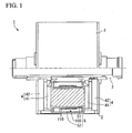
FIG. 1 is a partial exploded view of a schematic configuration of a superconducting motor according to an embodiment of the present invention. -
FIG 2 is a cross-sectional view of a schematic configuration of a superconducting coil assembly according to the embodiment. -
FIG 3 is a plan view of a magnetic field-adjusting ring according to the embodiment. -
FIG 4 is a cross-sectional view of the magnetic field-adjusting ring according toFIG 3 taken along the line X-X. -
FIG 5A is an explanatory schematic view of the effect of a magnetic field-adjusting ring according to the embodiment. -
FIG 5B is an explanatory schematic view of the effect of a magnetic field-adjusting ring according to the embodiment. -
FIG 6A is a simulation result of magnetic distribution of a superconducting coil assembly according to the embodiment. -
FIG 6B is a simulation result of magnetic distribution of a superconducting coil assembly according to the embodiment. -
FIG. 7A is an enlarged view of an end part of the superconducting coil assembly according toFIG. 6 . -
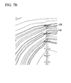
FIG 7B is an enlarged view of an end part of the superconducting coil assembly according toFIG 6 . - An embodiment of the present invention will be explained with reference to the drawings. Firstly, a schematic configuration of a superconducting motor (magnetic field generating equipment) including a superconducting coil assembly according to the embodiment will be explained.
-
FIG 1 is a partial exploded view of a schematic configuration of a superconducting motor 1 according to an embodiment of the present invention. - As shown in
FIG. 1 , the superconducting motor 1 includes a casing 2, amotor shaft 3, rotors 4, and a stator 5. - The casing 2 has a hollow circular cylindrical shape, and an opening is formed around its center axis to insert the
motor shaft 3. - The
motor shaft 3 is inserted into the opening in the casing 2, and rotates freely around a rotation axis extending in the axial direction with respect to the casing 2. - A pair of rotors 4 is provided inside the casing 2, and sandwich the stator 5 in the axial direction. The rotors 4 connected to the
motor shaft 3 can rotate freely with respect to the casing 2.Permanent magnets 41 are provided on one side of each rotor 4 and face the stator 5,back yokes 42 are also provided as a magnetic path on the back face of thepermanent magnet 41. - The stator 5 is provided inside the casing 2 and is fixed to the casing 2. The stator 5 includes
iron cores 51 which extend in the axial direction thereof and face thepermanent magnets 41,superconducting coil assemblies 100 provided around theiron cores 51, and acryostat 52 that surrounds thesuperconducting coil assemblies 100. - The
iron core 51 amplifies the magnetic flux generated by eachcoil unit 110, and gathers the magnetic flux. - The
superconducting coil assembly 100 includes a plurality ofcoil units 110 arranged coaxial to the same direction. Thesuperconducting coil assembly 100 generates a magnetic field by supplying driving current (AC current) to eachcoil unit 110 from outside. - The
cryostat 52 is a thermal insulation cooling medium container in order to keep thesuperconducting coil assemblies 100 at extremely low temperatures, and stores an extremely low-temperature cooling medium such as liquid nitrogen, liquid neon, or liquid helium. - In the superconducting motor 1 having the above-described configuration, AC current is supplied from outside to the
superconducting coil assemblies 100, thereby an N pole and an S pole are alternately generated at the ends of eachiron core 51 in accordance with the AC cycle. Attraction and repulsion forces act between theiron core 51 and thepermanent magnets 41 in the rotors 4, whereby the rotors 4 rotate around its axis. In response to the rotation of the rotors 4, themotor shaft 3 rotates with respect to the casing 2, and the superconducting motor 1 obtains a desired rotational driving force. - Subsequently, the configuration of the
superconducting coil assembly 100 of the superconducting motor 1 will be explained in detail with reference toFIGS. 2 to 4 . -
FIG 2 is a cross-sectional view of a schematic configuration of thesuperconducting coil assembly 100 according to the embodiment. -
FIG 3 is a plan view of a magnetic field-adjustingring 120 according to the embodiment. -
FIG. 4 is a cross-sectional view of the magnetic field-adjustingring 120 inFIG 3 taken along the line X-X. - As shown in
FIG 2 , thesuperconducting coil assembly 100 includescoil units 110 and magnetic field-adjusting rings 120. A gap as flow path of a cooling medium is provided between thecoil unit 110 and the magnetic field-adjustingring 120. - The
coil unit 110 is, for example, a so-called double pancake coil formed by winding a tape-shaped superconducting material that is bismuth-based, yttrium-based, or such like, around a bobbin in a two-layered pancake shape in the axial direction. Thecoil unit 110 can also be formed using superconducting material with a single-winding, or one in the shape of a fan, a racetrack-winding, and so forth. A plurality of thecoil units 110 are arranged with predetermined distances in the axial direction. - The magnetic field-adjusting
ring 120 is a member having higher magnetic permeability than the superconducting material which constitutes thecoil unit 110, and adjusts the strength of the magnetic field mainly in the direction perpendicular to the coil unit 110 (diameter direction). The magnetic field-adjustingrings 120 are positioned between thecoil units 110 so as to sandwich each of them in the axial direction. As shown inFIG. 3 , each magnetic field-adjustingring 120 is ring-shaped. - As shown in
FIG 4 , the magnetic field-adjustingring 120 includes magneticfield adjusting members 121, aninner ring member 122A, anouter ring member 122B, and thin-plate members 123. - In the embodiment, the magnetic
field adjusting members 121 are composed of ferrite, which has high electrical resistivity and high magnetic permeability. The ferrite is made by sintering of ferrite powder. Manganese ferrite can suitably be used. - As shown in
FIG 3 , the magneticfield adjusting members 121 have the shape of a ring divided into a plurality of sections in the circumferential direction. This configuration is selected after considering from the aspect of difficulty in forming into a single ring-shaped piece due to the brittleness of ferrite, and from the aspect of suppressing electric current due to alternating magnetic field. The plan-view shape of the divided pieces of the magneticfield adjusting members 121 can be circular-arc, trapezoidal, or rectangular. - If the magnetic
field adjusting members 121, which are soft magnetic material, have high electrical resistivity and conduct no current in alternating magnetic field, they need not to be divided in the circumferential direction, and can be formed into a single piece. - In order to suppress eddy current due to the alternating magnetic field, the adjacent magnetic
field adjusting members 121 are arranged with a fixed distance between them in the circumferential direction, and are electrically insulated from each other. The circumferential-direction ends of each magneticfield adjusting members 121 are coated with adhesive, or insulating sheets are inserted between adjacent magneticfield adjusting members 121, thereby the distance between adjacent magneticfield adjusting members 121 can be shortened as much as possible or there are no gaps between the distance between adjacent magneticfield adjusting members 121. - The
inner ring member 122A, theouter ring member 122B, and the thin-plate members 123 are members that together cover the magneticfield adjusting members 121 and hold it in a predetermined shape. Theinner ring member 122A, theouter ring member 122B, and the thin-plate members 123 are composed of fiber-reinforced plastic (FRP), which is a composition of resin material and fiber material, from the aspect of the thermal shrinkage factor and strength. - The
inner ring member 122A is positioned in the diameter-direction inner side of the ring shape of the magneticfield adjusting members 121. Theouter ring member 122B is positioned in the diameter-direction outer side of the ring shape of the magneticfield adjusting members 121. That is, the magneticfield adjusting members 121 is positioned between theinner ring member 122A and theouter ring member 122B in the diameter direction. Moreover, the magneticfield adjusting members 121 are enclosed in the axial direction by the pair of thin-plate members 123 together by theinner ring member 122A and theouter ring member 122B. - In order to protect the brittle magnetic
field adjusting members 121 from loads (e.g. a magnetic force acting on the magneticfield adjusting members 121 in the magnetic field, a force generated when fixing it to the coil stack, a force generated by difference in the thermal expansion coefficients between the ferrite and the resin material during cooling (or rising temperature), and so forth.), theinner ring member 122A and theouter ring member 122B are larger than the magneticfield adjusting members 121 in the axial direction. - The thin-
plate members 123 are formed in a sheet-like shape with a predetermined thickness that does not obstruct heat release of the magneticfield adjusting members 121. - Since the magnetic field-adjusting
ring 120 keeps its ring shape by the above-described configuration, and, when cracks appear in the brittle magneticfield adjusting members 121, the cracked piece can be prevented from protruding, whereby the desired functions can be maintained. - Returning to
FIG 2 , the magnetic field-adjustingrings 120 of the above-described configuration have a width in the axial direction or width in the direction intersecting the axis (diameter direction) that depend on the magnetic field distribution of their arrangement position. That is, considering the characteristic that their magnetic field distribution depends on the position in the axial direction of thesuperconducting coil assembly 100, the sizes of the magnetic field-adjusting rings 120 (more specifically, the magneticfield adjusting members 121 within them) are designed different. - In the embodiment, since the magnetic field is high at both ends of the
superconducting coil assembly 100, the width of the axial-direction of the magnetic field-adjustingring 120 is designed large. On the other hand, since the magnetic field is low around the center of thesuperconducting coil assembly 100, the width of the axial-direction of the magnetic field-adjustingring 120 is designed small. More precisely, the width of the axial-direction of the magnetic field-adjustingring 120 gradually decreases from both ends of thesuperconducting coil assembly 100 toward its center. - Subsequently, effects of the magnetic field-adjusting
ring 120 with the above-described configuration will be explained with reference toFIGS. 5A to 7B . -
FIGS. 5A and 5B are explanatory schematic views of effects of the magnetic field-adjustingring 120 according to an embodiment of the present invention. -
FIGS. 6A and6B are simulation results of magnetic distribution of thesuperconducting coil assembly 100 according to an embodiment of the present invention. -
FIGS. 7A and7B are expanded views of an end part of thesuperconducting coil assembly 100 according toFIGS. 6A and6B . - In
FIGS. 5A to 7B ,FIG 5A illustrates a case where the magnetic field-adjustingrings 120 are not provided, andFIG 5B illustrates a case where the magnetic field-adjustingrings 120 are provided.FIGS. 6A ,6B ,7A , and7B are simulation results when theiron core 51 is arranged on the axis of thesuperconducting coil assembly 100. - When AC current is supplied to the
superconducting coil assembly 100, a magnetic field is generated as shown inFIGS. 5A and 5B . - As shown in
FIG 5A , when thesuperconducting coil assembly 100 does not include the magnetic field-adjustingrings 120, the magnetic flux penetrates eachcoil unit 110 from the diameter direction of eachcoil unit 110. The critical current of the superconducting material forming thecoil unit 110 deteriorates, and AC loss (heat) is generated. The phenomenon that the magnetic flux penetrates thecoil units 110 can be also confirmed from the simulation results ofFIG 6A andFIG 7A . The magnetic flux density is high at the axial-direction ends of thesuperconducting coil assembly 100. On the other hand, the magnetic flux density is low at the axial-direction center of thesuperconducting coil assembly 100. - Referring to
FIG 5B , a case where thesuperconducting coil assembly 100 includes the magnetic field-adjustingrings 120 will be explained. The magneticfield adjusting members 121 of the magnetic field-adjustingring 120 consist of ferrite with a high magnetic permeability, and can sufficiently capture the magnetic flux. As seen inFIG 5B , the magnetic field-adjustingrings 120 capture the magnetic flux penetrating eachcoil unit 110 from the diameter direction such that the magnetic flux is drawn toward the magnetic field-adjustingring 120 provided in the vicinity of thatcoil unit 110, whereby the amount of magnetic flux penetrating eachcoil unit 110 can be reduced. - The capture of the magnetic flux by the magnetic field-adjusting
rings 120 can be confirmed from the simulation results shown inFIGS. 6B and7B . - As shown in
FIG 3 , since the adjacent divided pieces of magneticfield adjusting members 121 are electrically insulated from each other, heat generation due to current generated by the AC magnetic field is prevented. - The magnetic field-adjusting
rings 120 in the embodiment have axial-direction widths corresponding to their arrangement positions, and, as shown inFIGS. 6B and7B , at the axial-direction ends of thesuperconducting coil assembly 100, the magnetic field-adjustingrings 120 need to capture more magnetic flux. In contrast, the magnetic field-adjustingrings 120 do not need to capture much magnetic flux around the axial-direction center, and the magnetic field-adjustingrings 120 have smaller axial-direction widths than widths of ones positioned at the axial-direction ends. By setting the axial-direction width as appropriate, it is possible to prevent the magnetic field-adjusting ring from having an inadequate effect on thenearby coil units 110 by the magnetization of the magnetic field adjusting ring itself, and to suppress heat generation of the ferrite. - As described above, the magnetic field-adjusting
rings 120 can reduce the strength of the magnetic field acting on the superconducting material in the diameter direction, and suppress reduction of the critical current. In addition, the AC loss can also be reduced. - According to the embodiment, the
superconducting coil assembly 100 is formed by arranging a plurality ofcoil units 110 composed of superconducting material coaxial to the same direction, and includes, in the vicinities of thecoil units 110, magneticfield adjusting members 121 composed of ferrite having a higher magnetic permeability than the superconducting material. The magnetic field-adjustingring 120 has high electrical resistivity, and suppresses eddy current. In addition, the magnetic field-adjustingring 120 has high magnetic permeability, and can sufficiently capture magnetic flux. - Therefore, the embodiment can provide the
superconducting coil assembly 100 that further suppresses a reduction in critical current, and suppresses AC loss. - Furthermore, in the embodiment, the magnetic
field adjusting members 121 sandwich eachcoil unit 110 in the axial direction. Therefore, it is possible to capture the diameter-direction magnetic flux acting on eachcoil unit 110, and further reduce AC loss. - In the embodiment, the magnetic
field adjusting members 121 include the axial-direction width which depends on the magnetic field distribution at their arranged positions. Therefore, when the size of the magneticfield adjusting members 121 are adjusted depending on the magnetic field distribution, the magneticfield adjusting members 121 can possess the performance to capture magnetic flux appropriate to their arrangement positions. It is also possible to prevent effects which are opposite to the object of the present invention from arising due to the abilities of the magneticfield adjusting members 121 to capture magnetic flux and to have the magnetization. - In the embodiment, the magnetic field adjusting member has the shape of a ring coaxial to the axis of the
coil unit 110. Therefore, the magneticfield adjusting members 121 can capture magnetic flux in any direction acting on thecoil unit 110 from the diameter direction. - In the embodiment, the
inner ring member 122A provided on the diameter-direction inner sides of the magneticfield adjusting members 121, and theouter ring member 122B provided separately on the diameter-direction outer sides of the magneticfield adjusting members 121, are larger in the axial direction than the magneticfield adjusting members 121. Therefore, theinner ring member 122A and theouter ring member 122B can receive loads exerted on the magnetic field adjusting members 121 (e.g. a magnetic force acting on the magnetic body in the magnetic field, a force generated when securing it to the coil stack, a force generated by difference in the thermal expansion coefficients of the ferrite and the resin material during cooling (or rising temperature), etc.), whereby, even if the magneticfield adjusting members 121 are a brittle material such as ferrite, breaking and the like caused by load, impact and the like can be prevented. - In the embodiment, the superconducting motor 1 includes the
superconducting assemblies 100 described above and generates a magnetic field using drive current supplied to thecoil units 110 from outside. Therefore, the superconducting motor 1 which can suppress AC loss, can be operated stably and have high efficiently is achieved. - Although a preferred embodiment of the present invention has been described with reference to the drawings, it is not intended to be restrictive of the present invention. It will be understood that the shapes, combinations, and the like of the constituent members shown in the embodiment are merely examples, and can be modified in various ways for individual design demand based on the main points of the present invention.
- For example, although in the embodiment, ferrite is used as the magnetic
field adjusting members 121, this is not limitative of the present invention. For example, powder metallurgical core produced by pressing steel powder, or permendur powder, can also achieve the effects of the present invention. - In the embodiment, for example, the axial-direction width of the magnetic field-adjusting
ring 120 is increased to adjust the capture characteristics of the magnetic flux. However, this configuration is not limitative of the present invention, it is acceptable to adjust the width in the direction orthogonal to the axis (diameter direction) depending on the magnetic field distribution at the arranged position. Incidentally, the ability to capture the magnetic flux varies depending on the diameter-direction width of the magnetic field-adjustingring 120. Therefore, for example, the configuration which the diameter-direction width is large at the axial-direction ends of thesuperconducting coil assembly 100, while the diameter-direction width is small at the axial-direction center can be employed. - In the embodiment, for example, the magnetic
field adjusting members 121 sandwich eachcoil unit 110 in the axial direction. However, this is not limitative of the present invention. For example, they can be provided inside of the coil unit, or can sandwich coil units at both ends in the axial direction. Moreover, the arrangement positions of the magneticfield adjusting members 121 can be selected in accordance with the magnetic field distribution. For example, the configuration in which the magneticfield adjusting members 121 are not provided at the axial-direction centers where the diameter-direction magnetic field is weak, or in which the magneticfield adjusting members 121 are not provided in certain region in the circumferential direction can be employed. - In the embodiment, for example, the magnetic field generating equipment that includes the
superconducting coil assemblies 100 and generates a magnetic field using drive current supplied to thecoil unit 110 from outside, is the superconducting motor 1. However, the present invention is not limited to this configuration, and can be applied in various types of magnetic field generating equipments such as, for example, a transformer, a power generator, and an electromagnet. - The magnetic field adjusting member of the present invention has high electrical resistance, suppresses the generation of eddy current, has high magnetic permeability, and can capture magnetic flux.
-
- 1...SUPERCONDUCTING MOTOR (MAGNETIC FIELD GENERATING EQUIPMENT)
- 100...SUPERCONDUCTING COIL ASSEMBLY
- 110...COIL UNIT
- 121...MAGNETIC FIELD ADJUSTING MEMBERS
- 122A...INNER RING MEMBER
- 122B...OUTER RING MEMBER
Claims (3)
- A superconducting coil assembly (100) in which a plurality of coil units (110) composed of superconducting material are arranged coaxial to the same direction, comprising:magnetic field adjusting rings (120) being provided between said coil units (110) so as to sandwich each coil unit (110) in the axial direction, each magnetic field adjusting ring (120) comprising magnetic field adjusting members (121) forming the shape of a ring with its axis coaxial to each axis of said coil units (110), and composed of ferrite, powder metallurgical core, or permendur powder, which have higher magnetic permeability than the superconducting material, characterized in thateach said magnetic field adjusting ring (120) comprises an inner ring member (122A) provided on diameter-direction inner sides of the magnetic field adjusting members (121) of the respective magnetic field adjusting ring (120), an outer ring member (122B) provided separately on diameter-direction outer sides of the magnetic field adjusting members (121) of the respective magnetic field adjusting ring (120), the inner and outer ring members (122A, 122B) being composed of fiber-reinforced plastic which is a composition of resin material and fiber material,the inner and outer ring members (122A, 122B) are larger than the magnetic field adjusting members (121) in the axial direction thereby protecting the magnetic field adjusting members (121) from loads exerted on the magnetic field adjusting members (121).
- The superconducting coil assembly (100) according to claim 1, wherein the magnetic field adjusting rings (120) have widths in the axial direction and/or widths in a direction orthogonal to the axis that depend on magnetic field distribution at arranged positions thereof.
- A magnetic field generating equipment (1) comprising the superconducting coil assembly (100) according to claim 1, and generating a magnetic field using drive current supplied to each coil unit (110) from outside.
Applications Claiming Priority (2)
| Application Number | Priority Date | Filing Date | Title |
|---|---|---|---|
| JP2008202807A JP5201551B2 (en) | 2008-08-06 | 2008-08-06 | Superconducting coil and magnetic field generator |
| PCT/JP2009/003756 WO2010016254A1 (en) | 2008-08-06 | 2009-08-05 | Superconducting coil and magnetic field generator |
Publications (3)
| Publication Number | Publication Date |
|---|---|
| EP2323141A1 EP2323141A1 (en) | 2011-05-18 |
| EP2323141A4 EP2323141A4 (en) | 2012-12-12 |
| EP2323141B1 true EP2323141B1 (en) | 2014-05-21 |
Family
ID=41663482
Family Applications (1)
| Application Number | Title | Priority Date | Filing Date |
|---|---|---|---|
| EP09804741.8A Not-in-force EP2323141B1 (en) | 2008-08-06 | 2009-08-05 | Superconducting coil assembly and magnetic field generating equipment |
Country Status (7)
| Country | Link |
|---|---|
| US (1) | US8354907B2 (en) |
| EP (1) | EP2323141B1 (en) |
| JP (1) | JP5201551B2 (en) |
| KR (1) | KR20110046488A (en) |
| CA (1) | CA2733162C (en) |
| RU (1) | RU2479880C2 (en) |
| WO (1) | WO2010016254A1 (en) |
Families Citing this family (19)
| Publication number | Priority date | Publication date | Assignee | Title |
|---|---|---|---|---|
| JP2010263122A (en) * | 2009-05-08 | 2010-11-18 | Sumitomo Electric Ind Ltd | Superconducting coil body, superconducting equipment, rotor and stator |
| JP2011217480A (en) * | 2010-03-31 | 2011-10-27 | Sumitomo Electric Ind Ltd | Control system of superconducting motor |
| DE202011051056U1 (en) * | 2011-08-23 | 2011-11-21 | Intica Systems Ag | Inductive component |
| JP5310907B2 (en) * | 2011-08-26 | 2013-10-09 | 住友電気工業株式会社 | Superconducting coil body and superconducting equipment |
| EP2750146A4 (en) * | 2011-08-26 | 2015-06-24 | Sumitomo Electric Industries | SUPERCONDUCTING COIL AND SUPERCONDUCTING DEVICE |
| JP5310914B1 (en) * | 2012-08-13 | 2013-10-09 | 住友電気工業株式会社 | Superconducting equipment |
| CN104094368A (en) | 2012-01-30 | 2014-10-08 | 三菱电机株式会社 | Magnetic circuit |
| WO2013180802A1 (en) * | 2012-03-13 | 2013-12-05 | Massachusetts Institute Of Technology | No-insulation multi-width winding for high temperature superconducting magnets |
| JP6094233B2 (en) * | 2012-05-14 | 2017-03-15 | 住友電気工業株式会社 | Superconducting magnet |
| JP6262417B2 (en) * | 2012-07-31 | 2018-01-17 | 川崎重工業株式会社 | Magnetic field generator and superconducting rotating machine equipped with the same |
| JP5696694B2 (en) * | 2012-08-01 | 2015-04-08 | トヨタ自動車株式会社 | Rotating electric machine stator |
| AU2015400156A1 (en) | 2015-06-26 | 2017-11-02 | Halliburton Energy Services, Inc. | Antennas for wellbore logging tools and methods of manufacture |
| KR101706858B1 (en) * | 2015-08-11 | 2017-02-15 | 두산중공업 주식회사 | Vertical magnetic field reduction apparatus of the superconducting field coil |
| JP2020078362A (en) * | 2017-02-16 | 2020-05-28 | 株式会社日立製作所 | Superconducting magnet device or magnetic resonance imaging device using the same |
| CN107369520A (en) * | 2017-09-13 | 2017-11-21 | 云南电网有限责任公司电力科学研究院 | A kind of new type high temperature superconduction winding |
| JP2019161951A (en) * | 2018-03-15 | 2019-09-19 | 本田技研工業株式会社 | Rotating electrical machine stator |
| WO2021211082A1 (en) * | 2020-04-13 | 2021-10-21 | Tartar Ali Samil | A magnetic field routing and electric generation system |
| CN114551026B (en) * | 2022-03-02 | 2024-02-02 | 中国科学院电工研究所 | Superconducting magnet for low-temperature strong magnetic field comprehensive physical property measurement and design method thereof |
| US12494310B2 (en) * | 2023-02-28 | 2025-12-09 | Florida State University Research Foundation, Inc. | System and method to manage pancake deformation in REBCO wound magnet |
Family Cites Families (18)
| Publication number | Priority date | Publication date | Assignee | Title |
|---|---|---|---|---|
| SU1229827A1 (en) | 1984-08-01 | 1986-05-07 | Предприятие П/Я А-1758 | Superconductive winding |
| JPH03155103A (en) | 1989-11-14 | 1991-07-03 | Kawasaki Steel Corp | Manufacture of oxide superconductive ceramics coil |
| JPH05144628A (en) | 1991-11-18 | 1993-06-11 | Shin Etsu Chem Co Ltd | Magnetic field generator |
| JP3155103B2 (en) | 1992-12-17 | 2001-04-09 | 大日本印刷株式会社 | Exterior sheet and resin molded article using the exterior sheet |
| JPH07142245A (en) * | 1993-11-17 | 1995-06-02 | Mitsubishi Electric Corp | High temperature superconducting magnet, design method and operating method thereof, and method of manufacturing high temperature superconducting tape material |
| JP3117173B2 (en) | 1993-11-22 | 2000-12-11 | 株式会社日立製作所 | Superconducting magnet device with refrigerator |
| US5476633A (en) * | 1994-07-06 | 1995-12-19 | The United States Of America As Represented By The Administrator Of The National Aeronautics And Space Administration | Ultrahigh-purity dimensionally stable INVAR 36 |
| AU694296B2 (en) * | 1994-10-13 | 1998-07-16 | American Superconductor Corporation | Variable profile superconducting magnetic coil |
| JP3307565B2 (en) | 1997-06-20 | 2002-07-24 | 三菱電機株式会社 | Superconducting current limiting device |
| JPH1131614A (en) | 1997-07-10 | 1999-02-02 | Fuji Electric Co Ltd | High temperature superconducting coil |
| JP2001006920A (en) | 1999-06-25 | 2001-01-12 | Toshiba Corp | Superconducting wiggler magnet device |
| JP2002153441A (en) * | 2000-11-22 | 2002-05-28 | Hitachi Medical Corp | Magnetic resonance imaging device |
| DE10156212A1 (en) | 2001-11-15 | 2003-06-05 | Siemens Ag | Device for the electrical supply of at least one superconductor |
| JP2003158009A (en) | 2001-11-22 | 2003-05-30 | National Institute Of Advanced Industrial & Technology | High temperature superconducting coil |
| JP4409856B2 (en) * | 2003-05-19 | 2010-02-03 | 九州電力株式会社 | Superconducting coil |
| DE602004012035T2 (en) | 2003-10-15 | 2009-03-19 | Nexans | Superconducting current limiter with magnetic field-assisted quench |
| JP2007060748A (en) * | 2005-08-22 | 2007-03-08 | Sumitomo Electric Ind Ltd | Superconducting multi-axis motor and vehicle equipped with the same |
| JP2008202807A (en) | 2007-02-16 | 2008-09-04 | Noboru Masaoka | Environmental harmony system |
-
2008
- 2008-08-06 JP JP2008202807A patent/JP5201551B2/en not_active Expired - Fee Related
-
2009
- 2009-08-05 CA CA2733162A patent/CA2733162C/en not_active Expired - Fee Related
- 2009-08-05 KR KR1020117004227A patent/KR20110046488A/en not_active Ceased
- 2009-08-05 WO PCT/JP2009/003756 patent/WO2010016254A1/en not_active Ceased
- 2009-08-05 EP EP09804741.8A patent/EP2323141B1/en not_active Not-in-force
- 2009-08-05 RU RU2011108111/07A patent/RU2479880C2/en not_active IP Right Cessation
- 2009-08-05 US US13/057,594 patent/US8354907B2/en not_active Expired - Fee Related
Also Published As
| Publication number | Publication date |
|---|---|
| CA2733162A1 (en) | 2010-02-11 |
| US8354907B2 (en) | 2013-01-15 |
| EP2323141A1 (en) | 2011-05-18 |
| KR20110046488A (en) | 2011-05-04 |
| US20110140817A1 (en) | 2011-06-16 |
| CA2733162C (en) | 2014-09-23 |
| WO2010016254A1 (en) | 2010-02-11 |
| JP2010040823A (en) | 2010-02-18 |
| RU2011108111A (en) | 2012-09-20 |
| RU2479880C2 (en) | 2013-04-20 |
| JP5201551B2 (en) | 2013-06-05 |
| EP2323141A4 (en) | 2012-12-12 |
Similar Documents
| Publication | Publication Date | Title |
|---|---|---|
| CA2733162C (en) | Superconducting coil assembly and magnetic field generating equipment | |
| EP2490319B1 (en) | Axial gap motor | |
| US7294948B2 (en) | Rotor-stator structure for electrodynamic machines | |
| JP5576246B2 (en) | Axial gap type brushless motor | |
| JP4312245B2 (en) | Rotor / stator structure for electric machines | |
| EP2477198B1 (en) | System and method for magnetization of rare-earth permanent magnets | |
| US6441521B1 (en) | Hybrid superconducting motor/generator | |
| CA2711363C (en) | Superconducting magnetizer | |
| US10020716B2 (en) | Transverse flux induction motor with passive braking system | |
| US20150229168A1 (en) | Superconducting field pole | |
| Feng et al. | Design of a 100 kW surface permanent magnet machine with wide constant power speed ratio for traction applications | |
| Oswald et al. | Conceptual design of a SC HTS linear motor | |
| WO2018017895A1 (en) | Variable magnetic monopole field electro-magnet and inductor | |
| US11739402B2 (en) | Magnetic particles or wires for electrical machinery | |
| US11159077B2 (en) | Hybrid hysteresis motor | |
| US8339006B2 (en) | Permanent magnet arrangement for generator rotor | |
| US10056792B2 (en) | Interior permanent magnet electric machine | |
| EP1810391A2 (en) | Rotor-stator structure for electrodynamic machines | |
| JP5740250B2 (en) | Permanent magnet rotating electric machine | |
| JP4923301B2 (en) | Superconducting coil device, inductor-type synchronous machine, and transformer device | |
| KR20230069450A (en) | Axial permanent magnet motor with two-layer magnet structure | |
| JP2025169127A (en) | Permanent magnet motor and motor system |
Legal Events
| Date | Code | Title | Description |
|---|---|---|---|
| PUAI | Public reference made under article 153(3) epc to a published international application that has entered the european phase |
Free format text: ORIGINAL CODE: 0009012 |
|
| 17P | Request for examination filed |
Effective date: 20110221 |
|
| AK | Designated contracting states |
Kind code of ref document: A1 Designated state(s): AT BE BG CH CY CZ DE DK EE ES FI FR GB GR HR HU IE IS IT LI LT LU LV MC MK MT NL NO PL PT RO SE SI SK SM TR |
|
| AX | Request for extension of the european patent |
Extension state: AL BA RS |
|
| DAX | Request for extension of the european patent (deleted) | ||
| A4 | Supplementary search report drawn up and despatched |
Effective date: 20121108 |
|
| RIC1 | Information provided on ipc code assigned before grant |
Ipc: H01F 6/06 20060101AFI20121102BHEP Ipc: H01F 7/20 20060101ALI20121102BHEP Ipc: H01F 6/00 20060101ALI20121102BHEP |
|
| 17Q | First examination report despatched |
Effective date: 20130408 |
|
| GRAP | Despatch of communication of intention to grant a patent |
Free format text: ORIGINAL CODE: EPIDOSNIGR1 |
|
| INTG | Intention to grant announced |
Effective date: 20131129 |
|
| GRAS | Grant fee paid |
Free format text: ORIGINAL CODE: EPIDOSNIGR3 |
|
| GRAA | (expected) grant |
Free format text: ORIGINAL CODE: 0009210 |
|
| AK | Designated contracting states |
Kind code of ref document: B1 Designated state(s): AT BE BG CH CY CZ DE DK EE ES FI FR GB GR HR HU IE IS IT LI LT LU LV MC MK MT NL NO PL PT RO SE SI SK SM TR |
|
| REG | Reference to a national code |
Ref country code: GB Ref legal event code: FG4D |
|
| REG | Reference to a national code |
Ref country code: CH Ref legal event code: EP |
|
| REG | Reference to a national code |
Ref country code: AT Ref legal event code: REF Ref document number: 669964 Country of ref document: AT Kind code of ref document: T Effective date: 20140615 |
|
| REG | Reference to a national code |
Ref country code: IE Ref legal event code: FG4D |
|
| REG | Reference to a national code |
Ref country code: DE Ref legal event code: R096 Ref document number: 602009024319 Country of ref document: DE Effective date: 20140703 |
|
| REG | Reference to a national code |
Ref country code: NL Ref legal event code: VDEP Effective date: 20140521 Ref country code: AT Ref legal event code: MK05 Ref document number: 669964 Country of ref document: AT Kind code of ref document: T Effective date: 20140521 |
|
| REG | Reference to a national code |
Ref country code: LT Ref legal event code: MG4D |
|
| PG25 | Lapsed in a contracting state [announced via postgrant information from national office to epo] |
Ref country code: FI Free format text: LAPSE BECAUSE OF FAILURE TO SUBMIT A TRANSLATION OF THE DESCRIPTION OR TO PAY THE FEE WITHIN THE PRESCRIBED TIME-LIMIT Effective date: 20140521 Ref country code: LT Free format text: LAPSE BECAUSE OF FAILURE TO SUBMIT A TRANSLATION OF THE DESCRIPTION OR TO PAY THE FEE WITHIN THE PRESCRIBED TIME-LIMIT Effective date: 20140521 Ref country code: NO Free format text: LAPSE BECAUSE OF FAILURE TO SUBMIT A TRANSLATION OF THE DESCRIPTION OR TO PAY THE FEE WITHIN THE PRESCRIBED TIME-LIMIT Effective date: 20140821 Ref country code: GR Free format text: LAPSE BECAUSE OF FAILURE TO SUBMIT A TRANSLATION OF THE DESCRIPTION OR TO PAY THE FEE WITHIN THE PRESCRIBED TIME-LIMIT Effective date: 20140822 Ref country code: IS Free format text: LAPSE BECAUSE OF FAILURE TO SUBMIT A TRANSLATION OF THE DESCRIPTION OR TO PAY THE FEE WITHIN THE PRESCRIBED TIME-LIMIT Effective date: 20140921 |
|
| PGFP | Annual fee paid to national office [announced via postgrant information from national office to epo] |
Ref country code: DE Payment date: 20140730 Year of fee payment: 6 |
|
| PG25 | Lapsed in a contracting state [announced via postgrant information from national office to epo] |
Ref country code: PL Free format text: LAPSE BECAUSE OF FAILURE TO SUBMIT A TRANSLATION OF THE DESCRIPTION OR TO PAY THE FEE WITHIN THE PRESCRIBED TIME-LIMIT Effective date: 20140521 Ref country code: HR Free format text: LAPSE BECAUSE OF FAILURE TO SUBMIT A TRANSLATION OF THE DESCRIPTION OR TO PAY THE FEE WITHIN THE PRESCRIBED TIME-LIMIT Effective date: 20140521 Ref country code: ES Free format text: LAPSE BECAUSE OF FAILURE TO SUBMIT A TRANSLATION OF THE DESCRIPTION OR TO PAY THE FEE WITHIN THE PRESCRIBED TIME-LIMIT Effective date: 20140521 Ref country code: AT Free format text: LAPSE BECAUSE OF FAILURE TO SUBMIT A TRANSLATION OF THE DESCRIPTION OR TO PAY THE FEE WITHIN THE PRESCRIBED TIME-LIMIT Effective date: 20140521 Ref country code: SE Free format text: LAPSE BECAUSE OF FAILURE TO SUBMIT A TRANSLATION OF THE DESCRIPTION OR TO PAY THE FEE WITHIN THE PRESCRIBED TIME-LIMIT Effective date: 20140521 Ref country code: LV Free format text: LAPSE BECAUSE OF FAILURE TO SUBMIT A TRANSLATION OF THE DESCRIPTION OR TO PAY THE FEE WITHIN THE PRESCRIBED TIME-LIMIT Effective date: 20140521 |
|
| PGFP | Annual fee paid to national office [announced via postgrant information from national office to epo] |
Ref country code: FR Payment date: 20140808 Year of fee payment: 6 |
|
| PG25 | Lapsed in a contracting state [announced via postgrant information from national office to epo] |
Ref country code: PT Free format text: LAPSE BECAUSE OF FAILURE TO SUBMIT A TRANSLATION OF THE DESCRIPTION OR TO PAY THE FEE WITHIN THE PRESCRIBED TIME-LIMIT Effective date: 20140922 |
|
| PG25 | Lapsed in a contracting state [announced via postgrant information from national office to epo] |
Ref country code: DK Free format text: LAPSE BECAUSE OF FAILURE TO SUBMIT A TRANSLATION OF THE DESCRIPTION OR TO PAY THE FEE WITHIN THE PRESCRIBED TIME-LIMIT Effective date: 20140521 Ref country code: CZ Free format text: LAPSE BECAUSE OF FAILURE TO SUBMIT A TRANSLATION OF THE DESCRIPTION OR TO PAY THE FEE WITHIN THE PRESCRIBED TIME-LIMIT Effective date: 20140521 Ref country code: BE Free format text: LAPSE BECAUSE OF FAILURE TO SUBMIT A TRANSLATION OF THE DESCRIPTION OR TO PAY THE FEE WITHIN THE PRESCRIBED TIME-LIMIT Effective date: 20140521 Ref country code: SK Free format text: LAPSE BECAUSE OF FAILURE TO SUBMIT A TRANSLATION OF THE DESCRIPTION OR TO PAY THE FEE WITHIN THE PRESCRIBED TIME-LIMIT Effective date: 20140521 Ref country code: EE Free format text: LAPSE BECAUSE OF FAILURE TO SUBMIT A TRANSLATION OF THE DESCRIPTION OR TO PAY THE FEE WITHIN THE PRESCRIBED TIME-LIMIT Effective date: 20140521 Ref country code: RO Free format text: LAPSE BECAUSE OF FAILURE TO SUBMIT A TRANSLATION OF THE DESCRIPTION OR TO PAY THE FEE WITHIN THE PRESCRIBED TIME-LIMIT Effective date: 20140521 |
|
| REG | Reference to a national code |
Ref country code: DE Ref legal event code: R097 Ref document number: 602009024319 Country of ref document: DE |
|
| PG25 | Lapsed in a contracting state [announced via postgrant information from national office to epo] |
Ref country code: NL Free format text: LAPSE BECAUSE OF FAILURE TO SUBMIT A TRANSLATION OF THE DESCRIPTION OR TO PAY THE FEE WITHIN THE PRESCRIBED TIME-LIMIT Effective date: 20140521 |
|
| PLBE | No opposition filed within time limit |
Free format text: ORIGINAL CODE: 0009261 |
|
| STAA | Information on the status of an ep patent application or granted ep patent |
Free format text: STATUS: NO OPPOSITION FILED WITHIN TIME LIMIT |
|
| PG25 | Lapsed in a contracting state [announced via postgrant information from national office to epo] |
Ref country code: LU Free format text: LAPSE BECAUSE OF FAILURE TO SUBMIT A TRANSLATION OF THE DESCRIPTION OR TO PAY THE FEE WITHIN THE PRESCRIBED TIME-LIMIT Effective date: 20140805 Ref country code: MC Free format text: LAPSE BECAUSE OF FAILURE TO SUBMIT A TRANSLATION OF THE DESCRIPTION OR TO PAY THE FEE WITHIN THE PRESCRIBED TIME-LIMIT Effective date: 20140521 |
|
| REG | Reference to a national code |
Ref country code: CH Ref legal event code: PL |
|
| 26N | No opposition filed |
Effective date: 20150224 |
|
| GBPC | Gb: european patent ceased through non-payment of renewal fee |
Effective date: 20140821 |
|
| PG25 | Lapsed in a contracting state [announced via postgrant information from national office to epo] |
Ref country code: CH Free format text: LAPSE BECAUSE OF NON-PAYMENT OF DUE FEES Effective date: 20140831 Ref country code: BE Free format text: LAPSE BECAUSE OF FAILURE TO SUBMIT A TRANSLATION OF THE DESCRIPTION OR TO PAY THE FEE WITHIN THE PRESCRIBED TIME-LIMIT Effective date: 20140831 Ref country code: LI Free format text: LAPSE BECAUSE OF NON-PAYMENT OF DUE FEES Effective date: 20140831 Ref country code: IT Free format text: LAPSE BECAUSE OF FAILURE TO SUBMIT A TRANSLATION OF THE DESCRIPTION OR TO PAY THE FEE WITHIN THE PRESCRIBED TIME-LIMIT Effective date: 20140521 |
|
| REG | Reference to a national code |
Ref country code: IE Ref legal event code: MM4A |
|
| REG | Reference to a national code |
Ref country code: DE Ref legal event code: R097 Ref document number: 602009024319 Country of ref document: DE Effective date: 20150224 |
|
| PG25 | Lapsed in a contracting state [announced via postgrant information from national office to epo] |
Ref country code: SI Free format text: LAPSE BECAUSE OF FAILURE TO SUBMIT A TRANSLATION OF THE DESCRIPTION OR TO PAY THE FEE WITHIN THE PRESCRIBED TIME-LIMIT Effective date: 20140521 Ref country code: GB Free format text: LAPSE BECAUSE OF NON-PAYMENT OF DUE FEES Effective date: 20140821 |
|
| PG25 | Lapsed in a contracting state [announced via postgrant information from national office to epo] |
Ref country code: IE Free format text: LAPSE BECAUSE OF NON-PAYMENT OF DUE FEES Effective date: 20140805 |
|
| REG | Reference to a national code |
Ref country code: DE Ref legal event code: R119 Ref document number: 602009024319 Country of ref document: DE |
|
| PG25 | Lapsed in a contracting state [announced via postgrant information from national office to epo] |
Ref country code: SM Free format text: LAPSE BECAUSE OF FAILURE TO SUBMIT A TRANSLATION OF THE DESCRIPTION OR TO PAY THE FEE WITHIN THE PRESCRIBED TIME-LIMIT Effective date: 20140521 |
|
| REG | Reference to a national code |
Ref country code: FR Ref legal event code: ST Effective date: 20160429 |
|
| PG25 | Lapsed in a contracting state [announced via postgrant information from national office to epo] |
Ref country code: CY Free format text: LAPSE BECAUSE OF FAILURE TO SUBMIT A TRANSLATION OF THE DESCRIPTION OR TO PAY THE FEE WITHIN THE PRESCRIBED TIME-LIMIT Effective date: 20140521 Ref country code: MT Free format text: LAPSE BECAUSE OF FAILURE TO SUBMIT A TRANSLATION OF THE DESCRIPTION OR TO PAY THE FEE WITHIN THE PRESCRIBED TIME-LIMIT Effective date: 20140521 Ref country code: BG Free format text: LAPSE BECAUSE OF FAILURE TO SUBMIT A TRANSLATION OF THE DESCRIPTION OR TO PAY THE FEE WITHIN THE PRESCRIBED TIME-LIMIT Effective date: 20140521 |
|
| PG25 | Lapsed in a contracting state [announced via postgrant information from national office to epo] |
Ref country code: DE Free format text: LAPSE BECAUSE OF NON-PAYMENT OF DUE FEES Effective date: 20160301 Ref country code: TR Free format text: LAPSE BECAUSE OF FAILURE TO SUBMIT A TRANSLATION OF THE DESCRIPTION OR TO PAY THE FEE WITHIN THE PRESCRIBED TIME-LIMIT Effective date: 20140521 Ref country code: HU Free format text: LAPSE BECAUSE OF FAILURE TO SUBMIT A TRANSLATION OF THE DESCRIPTION OR TO PAY THE FEE WITHIN THE PRESCRIBED TIME-LIMIT; INVALID AB INITIO Effective date: 20090805 |
|
| PG25 | Lapsed in a contracting state [announced via postgrant information from national office to epo] |
Ref country code: FR Free format text: LAPSE BECAUSE OF NON-PAYMENT OF DUE FEES Effective date: 20150831 |
|
| PG25 | Lapsed in a contracting state [announced via postgrant information from national office to epo] |
Ref country code: MK Free format text: LAPSE BECAUSE OF FAILURE TO SUBMIT A TRANSLATION OF THE DESCRIPTION OR TO PAY THE FEE WITHIN THE PRESCRIBED TIME-LIMIT Effective date: 20140521 |