EP2322965A1 - Verfahren und Vorrichtung zum Stabilisieren einer Lichtleistung eines Beleuchtungslichtstrahls und Mikroskop - Google Patents
Verfahren und Vorrichtung zum Stabilisieren einer Lichtleistung eines Beleuchtungslichtstrahls und Mikroskop Download PDFInfo
- Publication number
- EP2322965A1 EP2322965A1 EP10013545A EP10013545A EP2322965A1 EP 2322965 A1 EP2322965 A1 EP 2322965A1 EP 10013545 A EP10013545 A EP 10013545A EP 10013545 A EP10013545 A EP 10013545A EP 2322965 A1 EP2322965 A1 EP 2322965A1
- Authority
- EP
- European Patent Office
- Prior art keywords
- light beam
- light
- illumination light
- light output
- useful
- Prior art date
- Legal status (The legal status is an assumption and is not a legal conclusion. Google has not performed a legal analysis and makes no representation as to the accuracy of the status listed.)
- Granted
Links
Images



Classifications
-
- G—PHYSICS
- G02—OPTICS
- G02B—OPTICAL ELEMENTS, SYSTEMS OR APPARATUS
- G02B21/00—Microscopes
- G02B21/0096—Microscopes with photometer devices
-
- G—PHYSICS
- G02—OPTICS
- G02B—OPTICAL ELEMENTS, SYSTEMS OR APPARATUS
- G02B21/00—Microscopes
- G02B21/0004—Microscopes specially adapted for specific applications
- G02B21/002—Scanning microscopes
-
- G—PHYSICS
- G02—OPTICS
- G02B—OPTICAL ELEMENTS, SYSTEMS OR APPARATUS
- G02B21/00—Microscopes
- G02B21/06—Means for illuminating specimens
Definitions
- the invention relates to a method and a device for stabilizing a light output of an illumination light beam for a scanning microscope.
- an illumination light beam is deflected within a scan field.
- the invention relates to a microscope comprising the device for stabilizing the light output.
- an illumination light beam is directed via one or more controllable deflection elements onto an object, in particular a sample, for example a tissue sample.
- a movement of the illumination light beam in particular a focus of the illumination light beam, is generated on or in the object.
- the focus area of the illumination light beam may be point or line-shaped.
- the deflection of the illumination light beam is such that a closed area can be scanned optically within or on the object.
- the focus area can be moved meandering over the sample.
- the detection beams emanating from the object which arise, for example, due to reflections and / or fluorescence effects in the object, are regularly detected by a detector unit. Outside of the image acquisition, especially when no object is to be examined, a power of the laser can be measured and adjusted depending on it, in order to avoid unwanted fluctuations in the laser power.
- the object of the invention is to provide an apparatus and a method for stabilizing a light output of an illumination light beam, which allow a consistently stable light output in a particularly simple manner.
- the invention is characterized in that a measured value, which is representative of the light output of the illuminating light beam striking the sample, is detected when the illuminating light beam is deflected in the direction of a blind region. Depending on the measured value, the light output of the illumination light beam is adjusted.
- the blind area is part of a scan field that includes an image field in addition to the blind area. Within the image field, a sample area of a sample is optically scanned. Within the blind area there is no optical scanning of the sample.
- the illumination light beam may include light of one or more wavelengths. That the illuminating light beam is deflected toward the blind area also includes shielding the illuminating light beam from the blind area, and means that the unshielded illuminating light beam is directed to the blind area due to the current setting of a scanner of the scanning microscope in the unshaded state.
- the light output can be controlled or regulated.
- the first modulator preferably makes it possible to extract individual laser lines from the illumination light beam, to suppress them, and / or to influence their light output, preferably independently of one another.
- a crystal of the modulator can be excited with oscillations of different amplitude for influencing the light output.
- the blind area comprises a picture advance, a picture return and / or a plurality of reversal points, within which a change in direction of the movement of the illumination light beam takes place.
- the image advance or the image return may comprise one or more parallel lines.
- illumination light of different wavelengths can be stabilized with regard to their light output.
- the light output transported at the individual wavelengths can be stabilized independently of the light of the other wavelengths.
- a first measured value representative of a first light power of the portion of the illumination light beam of the first wavelength can be detected when the illuminating light beam is directed towards a first portion of the blind area.
- a second reading representative of a second light power of the portion of the illumination light beam of the second wavelength may be detected.
- the first light output and, depending on the second measured value the second light output can be set.
- the first and / or the second subarea can each comprise one or more lines of the image advance or the image retrace and / or one or more reversal points. This enables the light output of the light before, during and / or after only a partial traversal of the image field stabilize the individual wavelengths.
- the illumination light beam is split into a useful beam and a measurement beam, wherein the useful beam is directed in the direction of the scan field and the measurement beam is directed onto a light-sensitive detector for detecting the measured value.
- the useful beam and / or the measuring beam are polarized such that the polarized illumination light beam, the polarized useful beam or the polarized measuring beam have the same polarization as the useful beam immediately before the impact of the sample. This contributes to the fact that the detected light power is proportional to the light power incident on the sample, resulting in polarization effects in the beam path of the useful beam when stabilizing the light output can be considered.
- a particularly strong measuring signal at the detector can be generated by increasing the light output, in particular maximizing it, during the detection of the measured value.
- the first modulator can be controlled so that the transmitted light power is maximum.
- the useful beam is deflected or shaded so that the sample is protected from the Nutzstrahl.
- the invention is characterized with respect to the device by a sensor, is directed to the photosensitive region of the measuring beam and by a scanner which deflects the useful beam in the direction of the scan field.
- a polarization filter which polarizes the illumination light beam such that the measurement beam impinging on the sensor has the same polarization as the useful beam impinging on the sample.
- the polarization filter can be seen in the beam path of the illumination light beam in the direction of the illumination light beam, be arranged before or after the beam splitter.
- the first modulator is arranged in the beam path of the illumination light beam.
- a second modulator can be provided in the beam path of the useful beam between the beam splitter and the scanner.
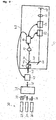
- FIG. 1 1 shows a scanning microscope 41 and a light source 20.
- the light source 20 comprises a first laser 22, a second laser 24 and a third laser 26.
- the first laser 22 generates a first light beam 30 and a second light beam 32.
- the second laser 24 generates a third laser beam
- Light beam 34 and the third laser 26 generates a fourth light beam 36.
- the individual light beams have light of different wavelengths.
- the first to fourth light beams 30, 32, 34, 36 are combined to form a common light beam 38.
- the common light beam 38 is coupled into a first modulator 42.
- the coupled-in light leaves the first modulator 42 in the form of an illumination light beam 44, which is coupled into the microscope 41, for example via an optical fiber.
- the illumination light beam 40 is split by means of a beam splitter 44 into a measurement beam 46 and a useful beam 48.
- the useful beam 48 is directed via one or more deflecting elements 50 to a second modulator 52 and via a scanner 54 to an imaging optical system 56 which directs the useful beam 48 onto an object, in particular a sample 58.
- the scanner 54 deflects the light of the useful beam 48 within a scan field on the sample 58.
- the measuring beam 46 is directed to a sensor 62 via a polarizing filter 60.
- the sensor 62 is coupled to a controller 64.
- the first and second modulators 42, 52 and the scanner 54 are coupled to the controller 64.
- the lasers 22, 24, 26 are narrow-band light sources and thus each produce light of individual, discrete wavelengths.
- the laser lines can extend from the ultraviolet to the infrared spectral range.
- a laser light source for example, a supercontinuum laser or white laser can be used. Alternatively, fewer lasers or more lasers may be provided. Further, one or more of the lasers may generate broadband light and thus light having a continuous spectrum of wavelengths.
- other light sources may also be used, for example one or more sources of mercury vapor light.
- the beam combiner 28 is preferably an acousto-optic beam combiner.
- the light of the light source 20 can also be coupled directly into the first modulator 42.
- the light source 20 can also be integrated in the microscope 41.
- the first modulator 42 preferably has a spectrally selective effect, so that light of individual wavelengths can be selected with it and the light output of the light of the individual wavelengths can be adjusted independently of one another. In particular, it is possible with the first modulator 42 to select precisely the light whose wavelengths coincide with the wavelengths of the light generated.
- the first modulator 42 is preferably an acousto-optically operating modulator, for example an AOTF.
- Acousto-optically operating modulators comprise at least one transparent crystal in which a sound wave can be induced, for example with the aid of one or more piezoactuators. By means of the frequency of the sound wave, light of individual wavelengths can be deflected and thereby selected or rejected.
- the power of the light of the corresponding wavelength can be adjusted.
- the frequency and power of the sound wave may also be referred to as adjustments of the modulator.
- the first modulator 42 allows to adjust the light output of the light of individual wavelengths.
- the polarization filter 60 can also be arranged in the beam path of the illumination light beam 40 in front of the beam splitter 44 and / or additionally in the beam path of the useful beam 48.
- the polarization filter 60 is designed such that the measurement beam incident on the sensor 62 has the same polarization as the useful beam 48 when it encounters the sample 58.
- the polarization filter 60 allows the light output of the useful beam 48 when hitting the sample 58 is always proportional to the light output of the measuring beam when hitting the sensor 62, whereby a polarization of the useful beam 48, for example due to the second modulator 52 and / or the scanner 54 and the imaging optics 56 is taken into account.
- the second modulator 52 is preferably an acousto-optical beam splitter (AOBS) or a main beam splitter system with a moudulator.
- the scanner 54 preferably operates galvanometrically or is a MEMS scanner. Optionally, the scanner 54 may also be integrated in the second modulator 52.
- the first and the second modulator 42, 52 and the scanner 54 are switched by means of the controller 64 and matched, in particular synchronized.
- the light output of the measuring beam 46 is detected as a measured value with the aid of the sensor 62.
- a measurement signal comprising, for example, many of the measurement values is then provided to the controller 64.
- the controller 64 controls the first module door 42 so that this light of different wavelengths with predetermined power pass.
- the first modulator 42 is set so that the zero order passing light or the first order light is used as the illumination light.
- the beam combiner 28 as well as the first modulator 42 do not act dispersively in contrast to a prism which has been widely used in conventional microscopes 41. Further, as compared with a conventional microscope 41, a spectrometer and a color filter can be saved.
- FIG. 2 shows an embodiment of the microscope 41, the up to the arrangement of the polarizing filter 60 according to the microscope according to FIG. 1 equivalent.
- the polarizing filter 60 is arranged in the direction of the illumination light beam 40 before the beam splitter 44.
- the polarizing filter 60 equally affects the useful beam 48 as the measuring beam 46.
- the function of the polarizing filter 60 remains opposite to that in FIG FIG. 1 illustrated embodiment unchanged.
- FIG. 3 shows a further embodiment of the microscope 41, the up to the arrangement of another polarizing filter 61 to the microscope 41 according to FIG. 1 equivalent.
- the further polarization filter 61 viewed in the direction of the illumination light beam 40, is arranged after the beam splitter 44 in the beam path of the useful beam 48.
- the further polarization filter 61 has an effect on the useful beam 48.
- the polarizing filters 60, 61 are coordinated so that the on the Sensor 62 incident measuring beam 46 has the same polarization as the useful beam 48 when hitting the sample 58.
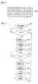
- FIG. 4 shows a scan field 80, within which by means of the scanner 54, a focus point of the useful beam 48 is deflected.
- the scan field 80 comprises a blind area and an image field B.
- detection beams emanating from the sample which are emitted by the sample 58, for example due to reflections or fluorescence effects, are detected by a detector, not shown, of the microscope 41.
- the image field B the optical scanning and the image acquisition of the sample 58 takes place.
- the dummy area which comprises a picture advance V, a plurality of reversal points X and a return R, no image recording takes place.
- a partial region of the image region B can also be scanned optically, in particular in the case of an ROI scan.
- Regular scanning is faster in the x-direction than in the y-direction, which means in FIG. 4 that scans horizontally faster than vertically.
- the power of the illumination light 40 may fluctuate due to thermal effects or drift from a predetermined value due to aging effects due to vibration, for example, when the light is coupled into the optical fiber, or due to warping of individual optical elements of the light source 20 or the microscope 41.
- the polarization and coupling efficiency of feeding optical fibers may vary, which may also result in power variation.
- FIG. 5 shows a flow chart of a program for operating the microscope 41, which is preferably stored on a storage medium of the control unit 64.
- the program serves to stabilize a light output of the illumination light beam 40.
- the program is started in a step S2 in which variables are initialized if necessary.
- a step S4 is triggered by a first instruction checks whether the illumination light beam 40, in particular the Nutzstrahl 48 is directed to the blind area, in particular the image advance V, the image return R or one of the reversal points X. If the condition of step S4 is satisfied, the processing is continued in step S6. If the condition of step S4 is not fulfilled, then step S4 is executed again.
- step S6 the light output of the illumination light beam 40 is raised by a second instruction RISE, which causes the first modulator 42 to transmit the maximum light output of the illumination light beam 40.
- a power POW of the exciting sound wave can be selected such that the light output becomes maximum.
- a transfer function of the first modulator 42 can be stored on the storage medium and taken into account by the control unit 64.
- the useful beam 48 is additionally shaded, for example with the aid of the second modulator 52.
- the light of the useful beam 48 can also be made via a modulatable shutter, ie an element for partially completely shielding the useful beam 48.
- the measured value MESS is detected.
- the measured value MESS is representative of the light output of the useful beam 48 when hitting the sample 58.
- a step S10 the power POW of the exciting sound wave in the first modulator 42 is adjusted so that the measured value MESS approaches a predetermined desired value.
- the first program can be ended.
- the first program is executed again in step S4.
- the light output of light of a different wavelength can then be stabilized.
- the program can now be processed continuously during image acquisition.
- different laser lines can be stabilized in different partial areas of the blind area.
- the light output of the first to fourth light beams 30, 32, 34, 36 can be successively stabilized.
- the image forward V comprises four lines
- the light output of all the laser lines shown can be stabilized even before the image is taken.
- the individual laser lines can each be stabilized in the reversal points.
- a constant light output of the individual laser lines can be ensured during image acquisition. This contributes to a particularly high quality of image acquisition.
- FIG. 6 shows a detail image of the scan field 80.
- the scan field 80 has a first image advance line V_1 and at least one second image advance line V_2. Furthermore, the scan field 80 has a plurality of reversal points X_1 to X_3.
- FIG. 7 12 shows a flow chart of a second program for stabilizing the light output of the illumination light beam 40.
- the second program is stored on the storage medium of the control unit 64 and serves to stabilize the light output of light of a first wavelength L1 and a second wavelength L2.
- the first light beam 30 the light of the first wavelength L1 and the second light beam 32, the light of the second wavelength L2.
- step S 14 the second program is started.
- step S16 is triggered by the first instruction checks whether the illumination light beam 40, in particular the Nutzstrahl 48 is directed to the first image advance line V_1. If the condition of step S 16 is satisfied, the processing is continued in a step S18. If the condition of step S 16 is not met, step S 16 is executed again.
- step S 18 the light output of the illumination light beam 40 is raised by the second instruction RISE, which causes the first modulator 42 to transmit the maximum light output of the light of the first wavelength L.
- the useful beam 48 is additionally shaded, for example with the aid of the second modulator 52.
- a first measured value MESS 1 is detected.
- the first measured value MESSI is representative of the light output of the light of the first wavelength L1 when hitting the sample 58.
- a step S22 the power POW of the exciting sound wave in the first modulator 42 is adjusted so that the first measured value MESS1 approaches a predetermined first setpoint value.
- step S24 triggered by the first instruction, it is checked whether the illumination light beam 40, in particular the useful beam 48, is directed onto the second image advance line V_2. If the condition of step S24 is satisfied, the processing is continued in step S26. If the condition of step S24 is not satisfied, step S24 is executed again.
- step S26 the light output of the second wavelength L2 light is raised by the second instruction RISE, which causes the first modulator 42 to transmit the maximum light output of the second wavelength L2 light.
- the useful beam 48 is additionally shaded, for example with the aid of the second modulator 52.
- a second measured value MESS2 is detected.
- the second measured value MESS2 is representative of the light output of the light of the second wavelength L2 when hitting the sample 58.
- a step S30 the power POW of the exciting sound wave in the first modulator 42 is set so that the second measured value MESS2 approaches a predetermined second setpoint value.
- the second program can be ended.
- the second program is executed for light of all wavelengths used.
- the measurements can also be made in the reversal points X and / or the individual lines of the R image return.
- the measurement of a laser line can also be made over several lines of the image advance V or the image return R or over several reversal points.
- the two algorithms for stabilizing the light output are closely woven into the scan logic of the scanning microscope.
- the controller 64 calculates the light power to be adjusted using the characteristic of the first modulator 42. This takes place both in the open and in the closed circuit and thus by control or regulation of the first modulator 42.
- reference measurements are performed at predetermined times. All available light sources are measured with their individual wavelengths. The recording can be performed, for example, at the beginning of the day, at each system start or after a fixed period of time. All subsequent measurements then refer to the last reference measurement made. As a result, more laser lines can be measured and stabilized, as measuring channels are present, in addition, the same performance can be reproduced even with independently successive measurements. Likewise, this leads to a lower control reserve, in particular to a higher available controlled laser power, since thus power drifts, over periods of weeks to years, such as aging effects need not be maintained.
Landscapes
- Physics & Mathematics (AREA)
- Chemical & Material Sciences (AREA)
- Analytical Chemistry (AREA)
- General Physics & Mathematics (AREA)
- Optics & Photonics (AREA)
- Microscoopes, Condenser (AREA)
Abstract
Description
- Die Erfindung betrifft ein Verfahren und eine Vorrichtung zum Stabilisieren einer Lichtleistung eines Beleuchtungslichtstrahls für ein Scanmikroskop. Dabei wird ein Beleuchtungslichtstrahl innerhalb eines Scanfeldes abgelenkt. Ferner betrifft die Erfindung ein Mikroskop, das die Vorrichtung zum Stabilisieren der Lichtleistung umfasst.
- Bei einem Scanmikroskop wird ein Beleuchtungslichtstrahl über eines oder mehrere steuerbare Umlenkelemente auf ein Objekt, insbesondere eine Probe, beispielsweise eine Gewebeprobe gerichtet. Durch Bewegen der Umlenkelemente wird eine Bewegung des Beleuchtungslichtstrahls, insbesondere eines Fokus des Beleuchtungslichtstrahls, auf oder in dem Objekt erzeugt. Der Fokusbereich des Beleuchtungslichtstrahls kann dabei punkt- oder linienförmig sein. Insgesamt erfolgt die Umlenkung des Beleuchtungslichtstrahls derart, dass ein geschlossener Bereich innerhalb oder auf dem Objekt optisch abgetastet werden kann. Beispielsweise kann der Fokusbereich mäanderförmig über die Probe bewegt werden. Dabei werden regelmäßig die von dem Objekt ausgehenden Detektionsstrahlen, die beispielsweise aufgrund von Reflektionen und/oder Fluoreszenzeffekten in dem Objekt entstehen, von einer Detektoreinheit erfasst. Außerhalb der Bildaufnahme, insbesondere, wenn kein Objekt zu untersuchen ist, kann eine Leistung des Lasers gemessen und davon abhängig angepasst werden, um ungewollte Schwankungen der Laserleistung zu vermeiden.
- Aufgabe der Erfindung ist es, eine Vorrichtung und ein Verfahren zum Stabilisieren einer Lichtleistung eines Beleuchtungslichtstrahls zu schaffen, die auf besonders einfache Weise eine gleichbleibend stabile Lichtleistung ermöglichen.
- Die Aufgabe wird gelöst durch die Merkmale der unabhängigen Ansprüche. Vorteilhafte Ausgestaltungen sind in den Unteransprüchen angegeben.
- Die Erfindung zeichnet sich gemäß einem ersten Aspekt dadurch aus, dass ein Messwert, der repräsentativ für die Lichtleistung des auf die Probe treffenden Beleuchtungslichtstrahls ist, erfasst wird, wenn der Beleuchtungslichtstrahl in Richtung eines Blindbereichs abgelenkt wird. Abhängig von dem Messwert wird die Lichtleistung des Beleuchtungslichtstrahls eingestellt. Der Blindbereich ist Teil eines Scanfeldes, das zusätzlich zu dem Blindbereich ein Bildfeld umfasst. Innerhalb des Bildfelds ist ein Probenbereich einer Probe optisch abtastbar ist. Innerhalb des Blindbereichs erfolgt keine optische Abtastung der Probe.
- Dies ermöglicht, die Lichtleistung parallel zur Bildaufnahme zu stabilisieren. Insbesondere können Leistungsabweichungen oder Schwankungen vor, während oder nach der Aufnahme einzelner Bilder, insbesondere einzelner Teilbereiche der Bilder beseitigt werden. Der Beleuchtungslichtstrahl kann dabei Licht einer oder mehrerer Wellenlängen umfassen. Dass der Beleuchtungslichtstrahl in Richtung des Blindbereichs abgelenkt wird, umfasst auch, dass der Beleuchtungslichtstrahl vor dem Blindbereich abgeschirmt wird, und bedeutet vielmehr, dass der nicht abgeschirmte Beleuchtungslichtstrahl aufgrund der aktuellen Einstellung eines Scanners des Scanmikroskops im nicht abgeschatteten Zustand auf den Blindbereich gelenkt wird .
- Mit Hilfe eines ersten Modulators, dessen Einstellung sich auf die Lichtleistung auswirkt, kann die Lichtleistung gesteuert oder geregelt werden. Der erste Modulator ermöglicht vorzugsweise zusätzlich zu dem Beeinflussen der Lichtleistung, einzelne Laserlinien aus dem Beleuchtungslichtstrahl auszukoppeln, zu unterdrücken und/oder deren Lichtleistung vorzugsweise unabhängig voneinander zu beeinflussen. Im Falle eines akusto-optischen Modulators kann zum Beeinflussen der Lichtleistung ein Kristall des Modulators mit Schwingungen unterschiedlicher Amplitude angeregt werden.
- Der Blindbereich umfasst einen Bildvorlauf, einen Bildrücklauf und/oder mehrere Umkehrpunkte, innerhalb der eine Richtungsänderung der Bewegung des Beleuchtungslichtstrahls erfolgt. Der Bildvorlauf bzw. der Bildrücklauf können eine oder mehrere parallele Linien umfassen.
- In einer vorteilhaften Weiterbildung kann Beleuchtungslicht unterschiedlicher Wellenlängen bezüglich deren Lichtleistung stabilisiert werden. Insbesondere kann die Lichtleistung, die mit den einzelnen Wellenlängen transportiert wird, unabhängig von dem Licht der anderen Wellenlängen stabilisiert werden. Falls beispielsweise der Beleuchtungslichtstrahl Licht einer ersten und zumindest einer zweiten Wellenlänge umfasst, kann ein erster Messwert erfasst werden, der repräsentativ für eine erste Lichtleistung des Anteils des Beleuchtungslichtstrahls der ersten Wellenlänge ist, wenn der Beleuchtungslichtstrahl in Richtung eines ersten Teilbereichs des Blindbereichs gelenkt wird. Wenn der Beleuchtungslichtstrahl dann in Richtung eines zweiten Teilbereichs des Blindbereichs gelenkt wird kann ein zweiter Messwert erfasst werden, der repräsentativ für eine zweite Lichtleistung des Anteils des Beleuchtungslichtstrahls der zweiten Wellenlänge ist. Abhängig von dem ersten Messwert kann die erste Lichtleistung und abhängig von dem zweiten Messwert die zweite Lichtleistung eingestellt werden. Dabei kann der erste und/oder der zweite Teilbereich je eine oder mehrere Zeilen des Bildvorlaufs oder des Bildrücklaufs und/oder einen oder mehrere Umkehrpunkte umfassen, Dies ermöglicht, vor, während und/oder nach einem auch nur teilweisen Durchlaufen des Bildfeldes die Lichtleistung des Lichts der einzelnen Wellenlängen zu stabilisieren.
- Vorzugsweise wird der Beleuchtungslichtstrahl in einen Nutzstrahl und einen Messstrahl aufgeteilt, wobei der Nutzstrahl in Richtung des Scanfeldes gelenkt wird und der Messstrahl zum Erfassen des Messwerts auf einen lichtempfindlichen Detektor gelenkt wird. In diesem Zusammenhang ist es besonders vorteilhaft, wenn der Nutzstrahl und/oder der Messstrahl so polarisiert werden, dass der polarisierte Beleuchtungslichtstrahl, der polarisierte Nutzstrahl bzw. der polarisierte Messstrahl die gleiche Polarisation aufweisen wie der Nutzstrahl unmittelbar vor Auftreffen der Probe. Dies trägt dazu bei, dass die erfasste Lichtleistung proportional zu der auf die Probe treffende Lichtleistung ist, wodurch Polarisationseffekte im Strahlengang des Nutzstrahls beim stabilisieren der Lichtleistung berücksichtigt werden können.
- Ein besonders starkes Messsignal am Detektor kann generiert werden, indem während des Erfassens des Messwerts die Lichtleistung erhöht, insbesondere maximiert wird. Dazu kann beispielsweise der erste Modulator so angesteuert werden, dass die durchgelassene Lichtleistung maximal ist. Um eine Beschädigung der Probe zu verhindern, wird der Nutzstrahl dabei so abgelenkt oder abgeschattet, dass die Probe vor dem Nutzstrahl geschützt ist.
- Die Erfindung zeichnet sich bezüglich der Vorrichtung durch einen Sensor aus, auf dessen lichtempfindlichen Bereich der Messstrahl gelenkt ist und durch einen Scanner, der den Nutzstrahl in Richtung des Scanfeldes ablenkt. In dem Strahlengang des Beleuchtungslichtstrahls ist ein Polarisationsfilter angeordnet, der den Beleuchtungslichtstrahl so polarisiert, dass der auf den Sensor treffende Messstrahl die gleiche Polarisation hat, wie der auf die Probe treffende Nutzstrahl. Der Polarisationsfilter kann dabei im Strahlengang des Beleuchtungslichtstrahls in Richtung des Beleuchtungslichtstrahls gesehen, vor oder nach dem Strahlteiler angeordnet sein. Zum Auswählen einzelner Wellenlängen und zum Beeinflussen der Lichtleistung des Lichts der einzelnen Wellenlängen ist der erste Modulator im Strahlengang des Beleuchtungslichtstrahls angeordnet. Zusätzlich kann im Strahlengang des Nutzstrahls zwischen Strahlteiler und Scanner ein zweiter Modulator vorgesehen sein.
- Ausführungsbeispiele der Erfindung sind im folgenden anhand von schematischen Zeichnungen näher erläutert.
- Es zeigen:
- Figur 1
- ein Scanmikroskop mit einer ersten Ausfüh- rungsform einer Vorrichtung zum Stabilisieren einer Lichtleistung eines Beleuchtungslicht- strahls,
- Figur 2
- das Scanmikroskop mit einer zweiten Ausfüh- rungsform der Vorrichtung zum Stabilisieren der Lichtleistung,
- Figur 3
- das Scanmikroskop mit einer dritten Ausfüh- rungsform der Vorrichtung zum Stabilisieren der Lichtleistung,
- Figur 4
- ein Scanfeld mit einem Bildbereich und einem Blindbereich,
- Figur 5
- ein Ablaufdiagramm eines ersten Programms zum Stabilisieren der Lichtleistung,
- Figur 6
- ein Detail-Ausschnitt aus dem Scanfeld gemäß
Figur 4 , - Figur 7
- ein Ablaufdiagramm eines zweiten Programms zum Stabilisieren der Lichtleistung.
- Elemente gleicher Konstruktion oder Funktion sind figrenübeigreifend mit den gleichen Bezugszeichen gekennzeichnet.
-
Figur 1 zeigt ein Scanmikroskop 41 und eine Lichtquelle 20. Die Lichtquelle 20 umfasst einen ersten Laser 22, einen zweiten Laser 24 und einen dritten Laser 26. Der erste Laser 22 erzeugt einen ersten Lichtstrahl 30 und einen zweiten Lichtstrahl 32. Der zweite Laser 24 erzeugt einen dritten Lichtstrahl 34 und der dritte Laser 26 erzeugt einen vierten Lichtstrahl 36. Die einzelnen Lichtstrahlen weisen Licht unterschiedlicher Wellenlängen auf. In einem Strahlvereiniger 28 werden die ersten bis vierten Lichtstrahlen 30, 32, 34, 36 zu einem gemeinsamen Lichtstrahl 38 vereinigt. Der gemeinsame Lichtstrahl 38 wird in einen ersten Modulator 42 eingekoppelt Das eingekoppelte Licht verlässt den ersten Modulator 42 in Form eines Beleuchtungslichtstrahls 44, der in das Mikroskop 41 eingekoppelt wird, beispielsweise über eine Lichtleitfaser. In dem Mikroskop 41, das auch einen Scankopf umfasst, wird der Beleuchtungslichtstrahl 40 mit Hilfe eines Strahlteilers 44 in einen Messstrahl 46 und einem Nutzstrahl 48 aufgeteilt. Der Nutzstrahl 48 wird über ein oder mehrere Umlenkelemente 50 auf einen zweiten Modulator 52 und über einen Scanner 54 auf eine abbildende Optik 56 gerichtet, die den Nutzstrahl 48 auf ein Objekt, insbesondere eine Probe 58 lenkt. Der Scanner 54 lenkt das Licht des Nutzstrahls 48 innerhalb eines Scanfeldes auf der Probe 58 ab. Der Messstrahl 46 wird über einen Polarisationsfilter 60 auf einen Sensor 62 gelenkt. Der Sensor 62 ist mit einer Steuerung 64 gekoppelt. Zusätzlich sind der erste und der zweite Modulator 42, 52 sowie der Scanner 54 mit der Steuerung 64 gekoppelt. - Die Laser 22, 24, 26 sind schmalbandige Lichtquellen und erzeugen somit jeweils Licht einzelner, diskreter Wellenlängen. Die Laserlinien können sich vom ultravioletten bis zum infraroten Spektralbereich erstrecken. Als Laserlichtquelle ist beispielsweise auch ein Supercontinuumslaser oder Weißlichtlaser verwendbar. Alternativ dazu können weniger Laser oder mehr Laser vorgesehen sein. Ferner können einer oder mehrere der Laser breitbandiges Licht und somit Licht mit einem kontinuierlich verlaufenden Spektrum an Wellenlängen erzeugen. Alternativ zu den Lasern können auch andere Lichtquellen verwendet werden, beispielsweise eine oder mehrere Quecksilberdampflichtquellen. Der Strahlvereiniger 28 ist vorzugsweise ein akusto-optischer Strahlvereiniger. Alternativ zum dem Strahlvereiniger 28 kann das Licht der Lichtquelle 20 auch direkt in den ersten Modulator 42 eingekoppelt werden. Alternativ zu der Lichtleitfaser zum Einkoppeln des Beleuchtungslichts in das Mikroskop kann die Lichtquelle 20 auch in dem Mikroskop 41 integriert sein.
- Der erste Modulator 42 wirkt vorzugsweise spektral selektiv, so dass mit ihm Licht einzelner Wellenlängen ausgewählt werden kann und die Lichtleistung des Lichts der einzelnen Wellenlängen unabhängig voneinander eingestellt werden kann. Insbesondere kann mit dem ersten Modulator 42 genau das Licht ausgewählt werden, dessen Wellenlängen mit den Wellenlängen des erzeugten Lichts übereinstimmt. Der erste Modulator 42 ist vorzugsweise ein akustooptisch arbeitender Modulator, beispielsweise ein AOTF. Akustooptisch arbeitende Modulatoren umfassen zumindest ein transparentes Kristall, in dem eine Schallwelle induziert werden kann, beispielsweise mit Hilfe eines oder mehrerer Piezoaktuatoren. Über die Frequenz der Schallwelle kann Licht einzelner Wellenlängen abgelenkt und dadurch ausgewählt oder aussortiert werden. Über die Leistung der Schallwelle und damit über deren Amplitude kann die Leistung des Lichts der entsprechenden Wellenlänge eingestellt werden. Die Frequenz und die Leistung der Schallwelle können auch als Einstellungen des Modulators bezeichnet werden, Somit ermöglicht der erste Modulator 42 die Lichtleistung des Lichts einzelner Wellenlängen einzustellen.
- Der Polarisationsfilter 60 kann alternativ auch im Strahlengang des Beleuchtungslichtstrahls 40 vor dem Strahlteiler 44 und/oder zusätzlich im Strahlengang des Nutzstrahls 48 angeordnet sein. Der Polarisationsfilter 60 ist so ausgebildet, dass der auf den Sensor 62 auftreffende Messstrahl die gleiche Polarisation wie der Nutzstrahl 48 beim Auftreffen auf die Probe 58 hat. Damit ermöglicht der Polarisationsfilter 60, dass die Lichtleistung des Nutzstrahls 48 beim Auftreffen auf die Probe 58 immer proportional zu der Lichtleistung des Messstrahls beim Auftreffen auf den Sensor 62 ist, wodurch eine Polarisation des Nutzstrahls 48 beispielsweise aufgrund des zweiten Modulators 52 und/oder des Scanners 54 sowie der abbildenden Optik 56 berücksichtigt wird.
- Der zweite Modulator 52 ist vorzugsweise ein akustooptischer Strahlteiler (AOBS) oder ein Hauptstrahlteilersystem mit einem Moudulator. Der Scanner 54 arbeitet vorzugsweise galvanometrisch oder ist ein MEMS-Scanner. Optional kann der Scanner 54 auch in dem zweiten Modulator 52 integriert sein. Der erste und der zweite Modulator 42, 52 und der Scanner 54 werden mit Hilfe der Steuerung 64 geschaltet und aufeinander abgestimmt, insbesondere synchronisiert. Die Lichtleistung des Messstrahls 46 wird als Messwert mit Hilfe des Sensors 62 erfasst. Ein Messsignal, das beispielsweise viele der Messwerte umfasst, wird dann der Steuerung 64 zur Verfügung gestellt. Die Steuerung 64 steuert dann den ersten Modultor 42 so an, dass dieser Licht unterschiedlicher Wellenlängen mit vorgegebener Leistung passieren lässt. Dabei wird der erste Modulator 42 so eingestellt, dass das passierende Licht der Ordnung null oder Licht erster Ordnung als Beleuchtungslicht verwendet wird.
- Der Strahlvereiniger 28 sowie der erste Modulator 42 wirken nicht dispersiv im Gegensatz zu einem Prisma, das bei herkömmlichen Mikroskopen 41 häufig Verwendung fand. Ferner kann gegenüber einem herkömmlichen Mikroskop 41 ein Spektrometer und ein Farbfilter eingespart werden.
-
Figur 2 zeigt eine Ausführungsform des Mikroskops 41, die bis auf die Anordnung des Polarisationsfilters 60 dem Mikroskop gemäßFigur 1 entspricht. Insbesondere ist bei dieser Ausführungsform der Polarisationsfilter 60 in Richtung des Beleuchtungslichtstrahls 40 gesehen vor dem Strahlteiler 44 angeordnet. Somit wirkt sich der Polarisationsfilter 60 gleichermaßen auf den Nutzstrahl 48 wie auf den Messstrahl 46 aus. Die Funktion des Polarisationsfilters 60 bleibt jedoch gegenüber der inFigur 1 dargestellten Ausführungsform unverändert. -
Figur 3 zeigt eine weitere Ausführungsform des Mikroskops 41, die bis auf die Anordnung eines weiteren Polarisationsfilters 61 dem Mikroskop 41 gemäßFigur 1 entspricht. Insbesondere ist der weitere Polarisationsfilter 61 in Richtung des Beleuchtungslichtstrahls 40 gesehen nach dem Strahlteiler 44 im Strahlengang des Nutzstrahls 48 angeordnet. Somit wirkt sich der weitere Polarisationsfilter 61 auf den Nutzstrahl 48 aus. Die Polarisationsfilter 60, 61 sind so aufeinander abgestimmt, dass der auf den Sensor 62 auftreffende Messstrahl 46 die gleiche Polarisation wie der Nutzstrahl 48 beim Auftreffen auf die Probe 58 hat. -
Figur 4 zeigt ein Scanfeld 80, innerhalb dessen mit Hilfe des Scanners 54 ein Fokuspunkt des Nutzstrahls 48 abgelenkt wird. Das Scanfeld 80 umfasst einen Blindbereich und ein Bildfeld B. Innerhalb des Bildfeldes B werden von der Probe ausgehende Detektionsstrahlen, die beispielsweise aufgrund von Reflektionen oder Fluoreszenzeffekten von der Probe 58 abgestrahlt werden, von einem nicht dargestellten Detektor des Mikroskops 41 erfasst. Somit erfolgt in dem Bildfeld B die optische Abtastung und die Bildaufnahme der Probe 58. In dem Blindbereich, der einen Bildvorlauf V, mehrere Umkehrpunkte X und einen Rücklauf R umfasst, erfolgt keine Bildaufnahme. Zur Bildaufnahme kann auch lediglich ein Teilbereich des Bildbereichs B optisch abgetastet werden, insbesondere bei einem ROI-Scan. Regelmäßig wird in x-Richtung schneller gescannt als in y-Richtung, das bedeutet inFigur 4 , dass horizontal schneller gescannt wird als vertikal. - Die Leistung des Beleuchtungslichts 40 kann beispielsweise aufgrund von Vibrationen, zum Beispiel beim Einkoppeln des Lichts in die Lichtleitfaser, oder aufgrund eines Verziehens einzelner optischer Elemente der Lichtquelle 20 oder des Mikroskops 41 aufgrund von thermischen Effekten schwanken oder aufgrund von Alterungseffekten von einem vorgegebenen Wert abdriften. Ferner können die Polarisation und die Koppeleffizienz von zuführenden Lichtleitfasern schwanken, was ebenso zu einer Leistungsschwankung führen kann.
-
Figur 5 zeigt ein Ablaufdiagramm eines Programms zum Betreiben des Mikroskops 41, das vorzugsweise auf einem Speichermedium der Steuereinheit 64 gespeichert ist. Das Programm dient dazu, eine Lichtleistung des Beleuchtungslichtstrahls 40 zu stabilisieren. - Das Programm wird in einem Schritt S2 gestartet, in dem gegebenenfalls Variablen initialisiert werden.
- In eine Schritt S4 wird ausgelöst durch eine erste Anweisung überprüft, ob der Beleuchtungslichtstrahl 40, insbesondere der Nutzstrahl 48 auf den Blindbereich, insbesondere den Bildvorlauf V, den Bildrücklauf R oder einen der Umkehrpunkte X gerichtet ist. Ist die Bedingung des Schritts S4 erfüllt, so wird die Bearbeitung in einem Schritt S6 fortgesetzt. Ist die Bedingung des Schritts S4 nicht erfüllt, so wird der Schritt S4 erneut abgearbeitet.
- In dem Schritt S6 wird die Lichtleistung des Beleuchtungslichtstrahls 40 ausgelöst durch eine zweite Anweisung RISE erhöht, die bewirkt, dass der erste Modulator 42 die maximale Lichtleistung des Beleuchtungslichtstrahls 40 durchlässt. Bei dem akusto-optischen Modulator kann dazu eine Leistung POW der anregenden Schallwelle so gewählt werden, dass die Lichtleistung maximal wird. Dazu kann eine Übertragungsfunktion des ersten Modulators 42 auf dem Speichermedium abgespeichert sein und von der Steuereinheit 64 berücksichtigt werden. Vorzugsweise wird in dem Schritt S6 zusätzlich der Nutzstrahl 48 abgeschattet, beispielsweise mit Hilfe des zweiten Modulators 52. Das Licht des Nutzstrahls 48 kann auch über einen modulierbaren Shutter, also ein Element zur teilweisen vollständigen Abschirmung des Nutzstrahls 48 vorgenommen werden.
- In einem Schritt S8 wird der Messwert MESS erfasst. Der Messwert MESS ist repräsentativ für die Lichtleistung des Nutzstrahls 48 beim Auftreffen auf die Probe 58.
- In einem Schritt S10 wird die Leistung POW der anregenden Schallwelle in dem ersten Modulator 42 so eingestellt, dass sich der Messwert MESS an einen vorgegebenen Sollwert annähert.
- In einem Schritt S12 kann das erste Programm beendet werden. Vorzugsweise wird das erste Programm jedoch in dem Schritt S4 erneut abgearbeitet. Bei jedem erneuten Abarbeiten, kann dann die Lichtleistung von Licht einer anderen Wellenlänge stabilisiert werden.
- Das Programm kann nun fortlaufend während der Bildaufnahme abgearbeitet werden. Dabei können in unterschiedlichen Teilbereichen des Blindbereichs unterschiedliche Laserlinien stabilisiert werden. Beispielsweise kann nacheinander die Lichtleistung der ersten bis vierten Lichtstrahlen 30, 32, 34, 36 stabilisiert werden. Falls beispielsweise der Bildvorlauf V vier Linien umfasst, kann die Lichtleistung aller dargestellten Laserlinien noch vor der Bildaufnahme stabilisiert werden. Alternativ oder zusätzlich können die einzelnen Laserlinien jeweils in den Umkehrpunkten stabilisiert werden. Somit kann während der Bildaufnahme eine gleichbleibende Lichtleistung der einzelnen Laserlinien gewährleistet werden. Dies trägt zu einer besonders hohen Qualität der Bildaufnahme bei.
-
Figur 6 zeigt eine Detail-Aufnahme des Scanfeldes 80. Das Scanfeld 80 weist eine erste Bildvorlauflinie V_1und zumindest eine zweite Bildvorlauflinie V_2 auf. Ferner weist das Scanfeld 80 mehrere Umkehrpunkte X_1 bis X_3 auf. -
Figur 7 zeigt ein Ablaufdiagramm eines zweiten Programms zum Stabilisieren der Lichtleistung des Beleuchtungslichtstrahls 40. Das zweite Programm ist auf dem Speichermedium der Steuereinheit 64 gespeichert und dient dazu die Lichtleistung von Licht einer ersten Wellenlänge L1 und einer zweiten Wellenlänge L2 zu stabilisieren. Beispielsweise weisen der erste Lichtstrahl 30 das Licht der ersten Wellenlänge L1 und der zweite Lichtstrahl 32 das Licht der zweiten Wellenlänge L2 auf. - In einem Schritt S 14 wird das zweite Programm gestartet.
- In eine Schritt S16 wird ausgelöst durch die erste Anweisung überprüft, ob der Beleuchtungslichtstrahl 40, insbesondere der Nutzstrahl 48 auf die erste Bildvorlauflinie V_1 gerichtet ist. Ist die Bedingung des Schritts S 16 erfüllt, so wird die Bearbeitung in einem Schritt S18 fortgesetzt, Ist die Bedingung des Schritts S 16 nicht erfüllt, so wird der Schritt S 16 erneut abgearbeitet.
- In dem Schritt S 18 wird die Lichtleistung des Beleuchtungslichtstrahls 40 ausgelöst durch die zweite Anweisung RISE erhöht, die bewirkt, dass der erste Modulator 42 die maximale Lichtleistung des Lichts der ersten Wellenlänge L durchlässt. Vorzugsweise wird in dem Schritt S18 zusätzlich der Nutzstrahl 48 abgeschattet, beispielsweise mit Hilfe des zweiten Modulators 52.
- In einem Schritt S20 wird ein erster Messwert MESS 1 erfasst. Der erste Messwert MESSI ist repräsentativ für die Lichtleistung des Lichts der ersten Wellenlänge L1 beim Auftreffen auf die Probe 58.
- In einem Schritt S22 wird die Leistung POW der anregenden Schallwelle in dem ersten Modulator 42 so eingestellt, dass sich der erste Messwert MESS1 an einen vorgegebenen ersten Sollwert annähert.
- In eine Schritt S24 wird ausgelöst durch die erste Anweisung überprüft, ob der Beleuchtungslichtstrahl 40, insbesondere der Nutzstrahl 48 auf die zweite Bildvorlauflinie V_2 gerichtet ist. Ist die Bedingung des Schritts S24 erfüllt, so wird die Bearbeitung in einem Schritt S26 fortgesetzt. Ist die Bedingung des Schritts S24 nicht erfüllt, so wird der Schritt S24 erneut abgearbeitet.
- In dem Schritt S26 wird die Lichtleistung des Lichts der zweiten Wellenlänge L2 ausgelöst durch die zweite Anweisung RISE erhöht, die bewirkt, dass der erste Modulator 42 die maximale Lichtleistung des Lichts der zweiten Wellenlänge L2 durchlässt. Vorzugsweise wird in dem Schritt S6 zusätzlich der Nutzstrahl 48 abgeschattet, beispielsweise mit Hilfe des zweiten Modulators 52.
- In einem Schritt S28 wird ein zweiter Messwert MESS2 erfasst. Der zweite Messwert MESS2 ist repräsentativ für die Lichtleistung des Lichts der zweiten Wellenlänge L2 beim Auftreffen auf die Probe 58.
- In einem Schritt S30 wird die Leistung POW der anregenden Schallwelle in dem ersten Modulator 42 so eingestellt, dass sich der zweite Messwert MESS2 an einen vorgegebenen zweiten Sollwert annähert.
- In einem Schritt S32 kann das zweite Programm beendet werden. Vorzugsweise wird das zweite Programm für Licht aller verwendeter Wellenlängen abgearbeitet. Dabei können die Messungen auch in den Umkehrpunkten X und/oder den einzelnen Linien des Bildrücklaufs R vorgenommen werden. Alternativ kann die Messung einer Laserlinie auch über mehrere Zeilen des Bildvorlaufs V oder des Bildrücklauf R oder über mehrere Umkehrpunkte hinweg vorgenommen werden.
- Die beiden Algorithmen zur Stabilisierung der Lichtleistung sind eng in die Scanlogic des Scan-Mikroskops eingewoben. Die Steuerung 64 berechnet mit Hilfe der Charakteristik des ersten Modulators 42 die einzustellende Lichtleistung,. Dies erfolgt sowohl im offenen als auch im geschlossenen Kreislaufund somit durch Steuerung bzw Regelung des ersten Modulators 42.
- Vorzugsweise werden zu vorgegebenen Zeiten Referenzmessungen durchgeführt. Dabei werden sämtliche verfügbare Lichtquellen mit deren einzelnen Wellenlängen gemessen. Die Aufnahme kann beispielsweise am Tagesbeginn, zu jedem Systemstart oder nach einer fest vorgegebenen Zeitdauer durchgeführt werden. Alle folgenden Messungen beziehen sich dann auf die zuletzt vorgenommene Referenzmessung. Dadurch können mehr Laserlinien gemessen und stabilisiert werden, als Messkanäle vorhanden sind, Zudem kann auch bei unabhängig aufeinanderfolgenden Messungen dieselbe Leistung reproduziert werden. Ebenso führt dies zu einer geringeren Regelreserve, insbesondere zu einer höheren verfügbaren gesteuerten Laserleistung, da damit Leistungsdrifts, über Zeiträume von Wochen bis Jahren, wie z.B. Alterungseffekte nicht vorgehalten werden müssen.
-
- 20
- Lichtquelle
- 22
- erster Laser
- 24
- zweiter Laser
- 26
- dritter Laser
- 30
- erster Lichtstrahl
- 32
- zweiter Lichtstrahl
- 34
- dritter Lichtstrahl
- 36
- vierter Lichtstrahl
- 28
- Strahlvereiniger
- 38
- gemeinsamer Lichtstrahl
- 42
- erster Modulator
- 40
- Beleuchtungslichtstrahl
- 41
- Mikroskop
- 44
- Strahlteiler
- 46
- Messstrahl
- 48
- Nutzstrahl
- 50
- Umlenkelement
- 52
- zweiter Modulator
- 54
- Scanner
- 56
- abbildende Optik
- 58
- Probe
- 60
- Polarisationsfilter
- 61
- weiterer Polarisationsfilter
- 62
- Sensor
- 64
- Steuereinheit
- 80
- Scanfeld
- START
- Programmstart
- V_1
- erste Bildvorlauflinie
- V_2
- zweite Bildvorlauflinie
- V
- Bildvorlauf
- X, X_1 ...
- Umkehrpunkte
- R
- Bildrücklauf
- B
- Bildfeld
- RISE
- zweite Anweisung
- L1
- erste Wellenlänge
- L2
- zweite Wellenlänge
- MESS
- Messwert
- MESS 1
- erster Messwert
- MESS2
- zweiter Messwert
- POW
- Leistung Schallwelle
- POW1
- Leistung erste Schallwelle
- POW2
- Leistung zweite Schallwelle
- END
- Programmende
- S2 bis S32
- Schritte zwei bis zweiundreißig
Claims (14)
- Verfahren zum Stabilisieren einer Lichtleistung eines Beleuchtungslichtstrahls (40) für ein Scan-Mikroskop (41),
bei dem der Beleuchtungstichtstrahl (40) innerhalb eines Scanfeldes (80) abgelenkt wird, das zumindest ein Bildfeld (B), in dem ein Probenbereich einer Probe (58) optisch abtastbar ist, und das zumindest einen Blindbereich (X, V, R) umfasst., in dem keine optische Abtastung der Probe (58) erfolgt, und
bei dem, wenn der Beleuchtungslichtstrahl (40) in Richtung des Blindbereichs (X, V, R) abgelenkt wird, ein Messwert (MESS) erfasst wird, der repräsentativ für die Lichtleistung des auf die Probe (58) treffenden Beleuchtungslichtstrahls (40) ist, und
bei dem abhängig von dem Messwert (MESS) die Lichtleistung des Beleuchtungslichtstrahls (40) eingestellt wird, wobei der Nutzstrahl (48) während des Erfassens des Messwerts (MESS) so abgelenkt oder abgeschattet wird, dass die Probe (58) vor dem Nutzstrahl (48) geschützt ist. - Verfahren nach Anspruch 1, bei dem zum Einstellen der Lichtleistung abhängig von dem Messwert (MESS) ein erster Modulator (42) angesteuert wird, dessen Einstellung sich auf die Lichtleistung auswirkt.
- Verfahren nach Anspruch 1, bei dem anhand mehrerer zeitlich nacheinander erfasster Messwerte (MESS) die Lichtleistung mittels eines ersten Modulators (42), dessen Einstellung sich auf die Lichtleistung auswirkt, auf einen vorgegebenen Sollwert der Lichtleistung geregelt wird.
- Verfahren nach einem der vorstehenden Ansprüche, bei dem der Blindbereich (X, V, R) zumindest einen Bildvorlauf (V), zumindest einen Bildrücklauf (R), und/oder mehrere Umkehrpunkte (X) umfasst, innerhalb der eine Richtungsänderung der Bewegung des Beleuchtungslichtstrahls (40) erfolgt.
- Verfahren nach einem der vorstehenden Ansprüche, bei dem der Beleuchtungslichtstrahl (40) Licht einer ersten und zumindest einer zweiten Wellenlänge (L1, L2) umfasst und bei dem, wenn der Beleuchtungslichtstrahl (40) in Richtung eines ersten Teilbereichs des Blindbereichs (X, V, R) gelenkt wird, ein erster Messwert (MESS 1) erfasst wird, der repräsentativ für eine erste Lichtleistung des Anteils des Beleuchtungslichtstrahls (40) der ersten Wellenlänge (LAM1) ist, und bei dem wenn der Beleuchtungslichtstrahl (40) in Richtung eines zweiten Teilbereichs des Blindbereichs (X, V, R) gelenkt wird, ein zweiter Messwert (MESS2) erfasst wird, der repräsentativ für eine zweite Lichtleistung des Anteils des Beleuchtungslichtstrahts (40) der zweiten Wellenlänge (32) ist, und bei dem abhängig von dem ersten Messwert (MESS1) die erste Lichtleistung und unabhängig von dem zweiten Messwert (MESS2) die zweite Lichtleistung eingestellt wird.
- Verfahren nach Anspruch 5, bei dem der erste und/oder der zweite Teilbereich je eine oder mehrere Zeilen (V_1, V_2) des Bildvorlaufs (V) und/oder des Bildrücklaufs (R), und/oder einen oder mehrere Umkehrpunkte (X_1 , X_2) umfassen,
- Verfahren nach einem der vorstehenden Ansprüche, bei dem der Beleuchtungslichtstrahl (40) in einen Nutzstrahl (48) und einen Messstrahl (46) aufgeteilt wird und bei dem der Nutzstrahl (48) in Richtung des Scanfelds (80) gelenkt wird und bei dem der Messstrahl (46) zum Erfassen des Messwerts (MESS) auf einen lichtempfindlichen Detektor (62) gelenkt wird,
- Verfahren nach Anspruch 7, bei dem der Beleuchtungslichtstrahl (40), der Nutzstrahl (48) und/oder der Messstrahl (46) so polarisiert werden, dass der polarisierte Beleuchtungslichtstrahl (40), der polarisierte Nutzstrahl (48) bzw. der polarisierte Messstrahl (46) die gleiche Polarisation aufweisen wie der Nutzstrahl (48) unmittelbar vor dem Auftreffen auf die Probe (58).
- Vorrichtung zur Stabilisierung einer Lichtleistung eines Beleuchtungslichtstrahls (40) nach Art eines Scan-Mikroskops,
mit einem Strahlteiler (44), der einen Beleuchtungslichtstrahl (40) in einen Messstrahl (46) und einen Nutzstrahl (48) aufteilt,
einen Sensor (62), auf dessen lichtempfindlichen Bereich der Messstrahl (46) gelenkt ist, zum Erfassen eines Messwerts (MESS), der repräsentativ für die Leistung des Nutzstrahls (48) beim Auftreffen auf die Probe (58) ist,
mit einem Scanner (54), der den Nutzstrahl (48) in Richtung eines Scanfelds (80) ablenkt,
und bei der im Strahlengang des Beleuchtungslichtstrahls (40) ein Polarisationsfilter (60) angeordnet ist, der den Beleuchtungslichtstrahl (40) so polarisiert, dass der auf den Sensor (62) treffende Messstrahl (46) die gleiche Polarisation hat wie der auf die Probe treffende Nutzstrahl (48), wobei der Scanner (54) den Nutzstrahl (48) während des Erfassens des Messwerts (MESS) so ablenkt, dass die Probe (58) vor dem Netzstrahl (48) geschützt ist. - Vorrichtung nach Anspruch 9, bei der der Polarisationsfilter (60) im Strahlengang des Beleuchtungslichtstrahls (40) in Richtung des Beleuchtungslichtstrahls (40) gesehen vor dem Strahlteiler (44) angeordnet ist.
- Vorrichtung nach Anspruch 9, bei der der Polarisationsfilter (60) im Strahlengang des Beleuchtungslichtstrahls (40) in Richtung des Beleuchtungslichtstrahls (40) gesehen nach dem Strahlteiler (44) angeordnet ist.
- Vorrichtung nach einem der Ansprüche 9 bis 11, bei der im Strahlengang des Beleuchtungslichtstrahls (40) vor dem Strahlteiler (44) ein erster Modulator (42) angeordnet ist, dessen Einstellung sich auf die Lichtleistung des Beleuchtungslichtstrahls (40) auswirkt.
- Vorrichtung nach einem der Ansprüche 9 bis 12, bei der ein zweiter Modulator (52) im Strahlengang des Nutzstrahls (48) zwischen Strahlteiler (44) und Scanner (54) angeordnet ist.
- Mikroskop nach Art eines Konfokalmikroskops, eines Scanmikroskops und/oder eines Fluoreszenzmikroskops, das die Vorrichtung nach einem der Ansprüche 9 bis 13 umfasst.
Applications Claiming Priority (1)
| Application Number | Priority Date | Filing Date | Title |
|---|---|---|---|
| DE200910049050 DE102009049050B4 (de) | 2009-10-12 | 2009-10-12 | Verfahren und Vorrichtung zum Stabilisieren einer Lichtleistung eines Beleuchtungslichtstrahls und Mikroskop |
Publications (2)
| Publication Number | Publication Date |
|---|---|
| EP2322965A1 true EP2322965A1 (de) | 2011-05-18 |
| EP2322965B1 EP2322965B1 (de) | 2013-04-17 |
Family
ID=43416245
Family Applications (1)
| Application Number | Title | Priority Date | Filing Date |
|---|---|---|---|
| EP20100013545 Not-in-force EP2322965B1 (de) | 2009-10-12 | 2010-10-12 | Verfahren und Vorrichtung zum Stabilisieren einer Lichtleistung eines Beleuchtungslichtstrahls und Mikroskop |
Country Status (2)
| Country | Link |
|---|---|
| EP (1) | EP2322965B1 (de) |
| DE (1) | DE102009049050B4 (de) |
Cited By (1)
| Publication number | Priority date | Publication date | Assignee | Title |
|---|---|---|---|---|
| CN113375905A (zh) * | 2021-05-31 | 2021-09-10 | 昆明物理研究所 | 红外光学瞄准具扫描摆镜转角范围及控制稳定性测量方法 |
Citations (5)
| Publication number | Priority date | Publication date | Assignee | Title |
|---|---|---|---|---|
| DE19702753A1 (de) * | 1997-01-27 | 1998-07-30 | Zeiss Carl Jena Gmbh | Laser-Scanning-Mikroskop |
| US20020041439A1 (en) * | 2000-10-11 | 2002-04-11 | Johann Engelhardt | Method for beam control in a scanning microscope, arrangement for beam control in a scanning microscope, and scanning microscope |
| US20020043622A1 (en) * | 2000-06-17 | 2002-04-18 | Holger Birk | Arrangement for studying microscopic preparations with a scanning microscope |
| WO2005031432A1 (de) * | 2003-09-25 | 2005-04-07 | Leica Microsystems Cms Gmbh | Beleuchtungsmodul zur evaneszenten beleuchtung und mikroskop |
| EP1780572A1 (de) * | 2003-07-11 | 2007-05-02 | CARL ZEISS JENA GmbH | Anordnung zur Erfassung der Beleuchtungsstrahlung in einem Laser-Scanning-Mikroskop |
Family Cites Families (2)
| Publication number | Priority date | Publication date | Assignee | Title |
|---|---|---|---|---|
| DE10324331A1 (de) * | 2003-05-27 | 2004-12-30 | Leica Microsystems Heidelberg Gmbh | Vorrichtung und Verfahren zur Regelung der Lichtleistung in einem Mikroskop, insbesondere in einem konfokalen Laserscanmikroskop |
| DE10324478B3 (de) * | 2003-05-30 | 2004-12-09 | Leica Microsystems Heidelberg Gmbh | Vorrichtung zum Ermitteln der Lichtleistung eines Lichtstrahles und Scanmikroskop |
-
2009
- 2009-10-12 DE DE200910049050 patent/DE102009049050B4/de active Active
-
2010
- 2010-10-12 EP EP20100013545 patent/EP2322965B1/de not_active Not-in-force
Patent Citations (5)
| Publication number | Priority date | Publication date | Assignee | Title |
|---|---|---|---|---|
| DE19702753A1 (de) * | 1997-01-27 | 1998-07-30 | Zeiss Carl Jena Gmbh | Laser-Scanning-Mikroskop |
| US20020043622A1 (en) * | 2000-06-17 | 2002-04-18 | Holger Birk | Arrangement for studying microscopic preparations with a scanning microscope |
| US20020041439A1 (en) * | 2000-10-11 | 2002-04-11 | Johann Engelhardt | Method for beam control in a scanning microscope, arrangement for beam control in a scanning microscope, and scanning microscope |
| EP1780572A1 (de) * | 2003-07-11 | 2007-05-02 | CARL ZEISS JENA GmbH | Anordnung zur Erfassung der Beleuchtungsstrahlung in einem Laser-Scanning-Mikroskop |
| WO2005031432A1 (de) * | 2003-09-25 | 2005-04-07 | Leica Microsystems Cms Gmbh | Beleuchtungsmodul zur evaneszenten beleuchtung und mikroskop |
Cited By (2)
| Publication number | Priority date | Publication date | Assignee | Title |
|---|---|---|---|---|
| CN113375905A (zh) * | 2021-05-31 | 2021-09-10 | 昆明物理研究所 | 红外光学瞄准具扫描摆镜转角范围及控制稳定性测量方法 |
| CN113375905B (zh) * | 2021-05-31 | 2022-08-19 | 昆明物理研究所 | 红外光学瞄准具扫描摆镜转角范围及控制稳定性测量方法 |
Also Published As
| Publication number | Publication date |
|---|---|
| EP2322965B1 (de) | 2013-04-17 |
| DE102009049050B4 (de) | 2011-07-21 |
| DE102009049050A1 (de) | 2011-04-14 |
Similar Documents
| Publication | Publication Date | Title |
|---|---|---|
| EP2347294B1 (de) | Verbesserte verfahren und vorrichtungen für die mikroskopie mit strukturierter beleuchtung | |
| EP2156235B1 (de) | Mikroskop und verfahren zum betreiben eines mikroskops | |
| DE102006025505B4 (de) | Konfokales Selbstinterferenz-Mikroskop ohne Nebenmaxima | |
| EP0168643B1 (de) | Gerät zur Wafer-Inspektion | |
| DE3586383T2 (de) | Bildaufnahmegeraet. | |
| DE112015000627B4 (de) | Mikrospektroskopische Vorrichtung | |
| DE10356826B4 (de) | Rastermikroskop | |
| EP3042233B1 (de) | Mikroskop mit einer akustooptischen vorrichtung | |
| DE10339311B4 (de) | System und Verfahren zur Einstellung eines Fluoreszenzspektralmesssystems zur Mikroskopie | |
| WO2008141903A1 (de) | Durchstimmbares akusto-optisches filterelement | |
| WO2018042056A1 (de) | Verfahren zum justieren eines laserscanning-fluoreszenzmikroskops und laserscanning-fluoreszenzmikroskop mit einer automatischen justiervorrichtung | |
| WO2014147261A1 (de) | Spim-anordnung | |
| DE10233074B4 (de) | Optische Vorrichtung zum Vereinigen von Lichtstrahlen und Scanmikroskop | |
| WO2012069443A1 (de) | Konfokales laser-scanmikroskop und ein verfahren zum untersuchen einer probe | |
| DE102021101658A1 (de) | Laserbearbeitungskopf mit chromatischer Kompensationsvorrichtung | |
| DE602004007319T2 (de) | Schnelles multispektrales konfokales Rastermikroskop | |
| DE102014003132A1 (de) | Vorrichtung und Verfahren zur Messung von Ramanstreuung | |
| DE10227111A1 (de) | Spektralmikroskop und Verfahren zur Datenaufnahme mit einem Spektralmikroskop | |
| DE102005047200B4 (de) | Verfahren zur Korrektur einer Steuerung eines optischen Scanners in einer Vorrichtung zur scannenden Abbildung einer Probe und Vorrichtung zur Erzeugung eines Bildes einer Probe durch Abscannen der Probe | |
| WO2017174792A1 (de) | Verfahren und mikroskop zum untersuchen einer probe | |
| EP2322965B1 (de) | Verfahren und Vorrichtung zum Stabilisieren einer Lichtleistung eines Beleuchtungslichtstrahls und Mikroskop | |
| DE102015112769B4 (de) | Vorrichtung und Verfahren zur optischen Probenuntersuchung | |
| EP1767979A1 (de) | Vorrichtung und Verfahren zur Detektion mit einem Scanmikroskop | |
| DE10331501B4 (de) | Justierung eines Mikroskops | |
| DE102016215177B4 (de) | Verfahren und Anordnung zur Erfassung von Bilddaten |
Legal Events
| Date | Code | Title | Description |
|---|---|---|---|
| PUAI | Public reference made under article 153(3) epc to a published international application that has entered the european phase |
Free format text: ORIGINAL CODE: 0009012 |
|
| AK | Designated contracting states |
Kind code of ref document: A1 Designated state(s): AL AT BE BG CH CY CZ DE DK EE ES FI FR GB GR HR HU IE IS IT LI LT LU LV MC MK MT NL NO PL PT RO RS SE SI SK SM TR |
|
| AX | Request for extension of the european patent |
Extension state: BA ME |
|
| 17P | Request for examination filed |
Effective date: 20111111 |
|
| RIC1 | Information provided on ipc code assigned before grant |
Ipc: G02B 21/06 20060101AFI20111230BHEP |
|
| GRAP | Despatch of communication of intention to grant a patent |
Free format text: ORIGINAL CODE: EPIDOSNIGR1 |
|
| RIN1 | Information on inventor provided before grant (corrected) |
Inventor name: SEYFRIED, VOLKER Inventor name: WIDZGOWSKI, BERND Inventor name: BIRK, HOLGER Inventor name: WARKEN, FLORIAN |
|
| GRAS | Grant fee paid |
Free format text: ORIGINAL CODE: EPIDOSNIGR3 |
|
| GRAA | (expected) grant |
Free format text: ORIGINAL CODE: 0009210 |
|
| AK | Designated contracting states |
Kind code of ref document: B1 Designated state(s): AL AT BE BG CH CY CZ DE DK EE ES FI FR GB GR HR HU IE IS IT LI LT LU LV MC MK MT NL NO PL PT RO RS SE SI SK SM TR |
|
| REG | Reference to a national code |
Ref country code: GB Ref legal event code: FG4D Free format text: NOT ENGLISH |
|
| REG | Reference to a national code |
Ref country code: CH Ref legal event code: EP |
|
| REG | Reference to a national code |
Ref country code: IE Ref legal event code: FG4D Free format text: LANGUAGE OF EP DOCUMENT: GERMAN |
|
| REG | Reference to a national code |
Ref country code: AT Ref legal event code: REF Ref document number: 607638 Country of ref document: AT Kind code of ref document: T Effective date: 20130515 |
|
| REG | Reference to a national code |
Ref country code: DE Ref legal event code: R096 Ref document number: 502010002917 Country of ref document: DE Effective date: 20130613 |
|
| REG | Reference to a national code |
Ref country code: LT Ref legal event code: MG4D |
|
| REG | Reference to a national code |
Ref country code: NL Ref legal event code: VDEP Effective date: 20130417 |
|
| PG25 | Lapsed in a contracting state [announced via postgrant information from national office to epo] |
Ref country code: IS Free format text: LAPSE BECAUSE OF FAILURE TO SUBMIT A TRANSLATION OF THE DESCRIPTION OR TO PAY THE FEE WITHIN THE PRESCRIBED TIME-LIMIT Effective date: 20130817 Ref country code: SI Free format text: LAPSE BECAUSE OF FAILURE TO SUBMIT A TRANSLATION OF THE DESCRIPTION OR TO PAY THE FEE WITHIN THE PRESCRIBED TIME-LIMIT Effective date: 20130417 Ref country code: LT Free format text: LAPSE BECAUSE OF FAILURE TO SUBMIT A TRANSLATION OF THE DESCRIPTION OR TO PAY THE FEE WITHIN THE PRESCRIBED TIME-LIMIT Effective date: 20130417 Ref country code: GR Free format text: LAPSE BECAUSE OF FAILURE TO SUBMIT A TRANSLATION OF THE DESCRIPTION OR TO PAY THE FEE WITHIN THE PRESCRIBED TIME-LIMIT Effective date: 20130718 Ref country code: ES Free format text: LAPSE BECAUSE OF FAILURE TO SUBMIT A TRANSLATION OF THE DESCRIPTION OR TO PAY THE FEE WITHIN THE PRESCRIBED TIME-LIMIT Effective date: 20130728 Ref country code: FI Free format text: LAPSE BECAUSE OF FAILURE TO SUBMIT A TRANSLATION OF THE DESCRIPTION OR TO PAY THE FEE WITHIN THE PRESCRIBED TIME-LIMIT Effective date: 20130417 Ref country code: NO Free format text: LAPSE BECAUSE OF FAILURE TO SUBMIT A TRANSLATION OF THE DESCRIPTION OR TO PAY THE FEE WITHIN THE PRESCRIBED TIME-LIMIT Effective date: 20130717 Ref country code: SE Free format text: LAPSE BECAUSE OF FAILURE TO SUBMIT A TRANSLATION OF THE DESCRIPTION OR TO PAY THE FEE WITHIN THE PRESCRIBED TIME-LIMIT Effective date: 20130417 Ref country code: PT Free format text: LAPSE BECAUSE OF FAILURE TO SUBMIT A TRANSLATION OF THE DESCRIPTION OR TO PAY THE FEE WITHIN THE PRESCRIBED TIME-LIMIT Effective date: 20130819 |
|
| PG25 | Lapsed in a contracting state [announced via postgrant information from national office to epo] |
Ref country code: PL Free format text: LAPSE BECAUSE OF FAILURE TO SUBMIT A TRANSLATION OF THE DESCRIPTION OR TO PAY THE FEE WITHIN THE PRESCRIBED TIME-LIMIT Effective date: 20130417 Ref country code: CY Free format text: LAPSE BECAUSE OF FAILURE TO SUBMIT A TRANSLATION OF THE DESCRIPTION OR TO PAY THE FEE WITHIN THE PRESCRIBED TIME-LIMIT Effective date: 20130417 Ref country code: LV Free format text: LAPSE BECAUSE OF FAILURE TO SUBMIT A TRANSLATION OF THE DESCRIPTION OR TO PAY THE FEE WITHIN THE PRESCRIBED TIME-LIMIT Effective date: 20130417 Ref country code: HR Free format text: LAPSE BECAUSE OF FAILURE TO SUBMIT A TRANSLATION OF THE DESCRIPTION OR TO PAY THE FEE WITHIN THE PRESCRIBED TIME-LIMIT Effective date: 20130417 Ref country code: RS Free format text: LAPSE BECAUSE OF FAILURE TO SUBMIT A TRANSLATION OF THE DESCRIPTION OR TO PAY THE FEE WITHIN THE PRESCRIBED TIME-LIMIT Effective date: 20130417 Ref country code: BG Free format text: LAPSE BECAUSE OF FAILURE TO SUBMIT A TRANSLATION OF THE DESCRIPTION OR TO PAY THE FEE WITHIN THE PRESCRIBED TIME-LIMIT Effective date: 20130717 |
|
| PG25 | Lapsed in a contracting state [announced via postgrant information from national office to epo] |
Ref country code: DK Free format text: LAPSE BECAUSE OF FAILURE TO SUBMIT A TRANSLATION OF THE DESCRIPTION OR TO PAY THE FEE WITHIN THE PRESCRIBED TIME-LIMIT Effective date: 20130417 Ref country code: SK Free format text: LAPSE BECAUSE OF FAILURE TO SUBMIT A TRANSLATION OF THE DESCRIPTION OR TO PAY THE FEE WITHIN THE PRESCRIBED TIME-LIMIT Effective date: 20130417 Ref country code: EE Free format text: LAPSE BECAUSE OF FAILURE TO SUBMIT A TRANSLATION OF THE DESCRIPTION OR TO PAY THE FEE WITHIN THE PRESCRIBED TIME-LIMIT Effective date: 20130417 Ref country code: CZ Free format text: LAPSE BECAUSE OF FAILURE TO SUBMIT A TRANSLATION OF THE DESCRIPTION OR TO PAY THE FEE WITHIN THE PRESCRIBED TIME-LIMIT Effective date: 20130417 |
|
| PLBE | No opposition filed within time limit |
Free format text: ORIGINAL CODE: 0009261 |
|
| STAA | Information on the status of an ep patent application or granted ep patent |
Free format text: STATUS: NO OPPOSITION FILED WITHIN TIME LIMIT |
|
| PG25 | Lapsed in a contracting state [announced via postgrant information from national office to epo] |
Ref country code: NL Free format text: LAPSE BECAUSE OF FAILURE TO SUBMIT A TRANSLATION OF THE DESCRIPTION OR TO PAY THE FEE WITHIN THE PRESCRIBED TIME-LIMIT Effective date: 20130417 Ref country code: IT Free format text: LAPSE BECAUSE OF FAILURE TO SUBMIT A TRANSLATION OF THE DESCRIPTION OR TO PAY THE FEE WITHIN THE PRESCRIBED TIME-LIMIT Effective date: 20130417 Ref country code: RO Free format text: LAPSE BECAUSE OF FAILURE TO SUBMIT A TRANSLATION OF THE DESCRIPTION OR TO PAY THE FEE WITHIN THE PRESCRIBED TIME-LIMIT Effective date: 20130417 |
|
| 26N | No opposition filed |
Effective date: 20140120 |
|
| BERE | Be: lapsed |
Owner name: LEICA MICROSYSTEMS CMS G.M.B.H. Effective date: 20131031 |
|
| REG | Reference to a national code |
Ref country code: DE Ref legal event code: R097 Ref document number: 502010002917 Country of ref document: DE Effective date: 20140120 |
|
| PG25 | Lapsed in a contracting state [announced via postgrant information from national office to epo] |
Ref country code: MC Free format text: LAPSE BECAUSE OF FAILURE TO SUBMIT A TRANSLATION OF THE DESCRIPTION OR TO PAY THE FEE WITHIN THE PRESCRIBED TIME-LIMIT Effective date: 20130417 |
|
| REG | Reference to a national code |
Ref country code: IE Ref legal event code: MM4A |
|
| PG25 | Lapsed in a contracting state [announced via postgrant information from national office to epo] |
Ref country code: BE Free format text: LAPSE BECAUSE OF NON-PAYMENT OF DUE FEES Effective date: 20131031 |
|
| PG25 | Lapsed in a contracting state [announced via postgrant information from national office to epo] |
Ref country code: IE Free format text: LAPSE BECAUSE OF NON-PAYMENT OF DUE FEES Effective date: 20131012 |
|
| REG | Reference to a national code |
Ref country code: DE Ref legal event code: R082 Ref document number: 502010002917 Country of ref document: DE Representative=s name: SCHAUMBURG & PARTNER PATENTANWAELTE GBR, DE Ref country code: DE Ref legal event code: R082 Ref document number: 502010002917 Country of ref document: DE Representative=s name: SCHAUMBURG & PARTNER PATENTANWAELTE MBB, DE Ref country code: DE Ref legal event code: R082 Ref document number: 502010002917 Country of ref document: DE Representative=s name: SCHAUMBURG UND PARTNER PATENTANWAELTE MBB, DE |
|
| PG25 | Lapsed in a contracting state [announced via postgrant information from national office to epo] |
Ref country code: SM Free format text: LAPSE BECAUSE OF FAILURE TO SUBMIT A TRANSLATION OF THE DESCRIPTION OR TO PAY THE FEE WITHIN THE PRESCRIBED TIME-LIMIT Effective date: 20130417 |
|
| REG | Reference to a national code |
Ref country code: CH Ref legal event code: PL |
|
| PG25 | Lapsed in a contracting state [announced via postgrant information from national office to epo] |
Ref country code: TR Free format text: LAPSE BECAUSE OF FAILURE TO SUBMIT A TRANSLATION OF THE DESCRIPTION OR TO PAY THE FEE WITHIN THE PRESCRIBED TIME-LIMIT Effective date: 20130417 |
|
| PG25 | Lapsed in a contracting state [announced via postgrant information from national office to epo] |
Ref country code: HU Free format text: LAPSE BECAUSE OF FAILURE TO SUBMIT A TRANSLATION OF THE DESCRIPTION OR TO PAY THE FEE WITHIN THE PRESCRIBED TIME-LIMIT; INVALID AB INITIO Effective date: 20101012 Ref country code: LI Free format text: LAPSE BECAUSE OF NON-PAYMENT OF DUE FEES Effective date: 20141031 Ref country code: MK Free format text: LAPSE BECAUSE OF FAILURE TO SUBMIT A TRANSLATION OF THE DESCRIPTION OR TO PAY THE FEE WITHIN THE PRESCRIBED TIME-LIMIT Effective date: 20130417 Ref country code: CH Free format text: LAPSE BECAUSE OF NON-PAYMENT OF DUE FEES Effective date: 20141031 Ref country code: LU Free format text: LAPSE BECAUSE OF NON-PAYMENT OF DUE FEES Effective date: 20131012 |
|
| PG25 | Lapsed in a contracting state [announced via postgrant information from national office to epo] |
Ref country code: MT Free format text: LAPSE BECAUSE OF FAILURE TO SUBMIT A TRANSLATION OF THE DESCRIPTION OR TO PAY THE FEE WITHIN THE PRESCRIBED TIME-LIMIT Effective date: 20130417 |
|
| REG | Reference to a national code |
Ref country code: FR Ref legal event code: PLFP Year of fee payment: 6 |
|
| REG | Reference to a national code |
Ref country code: FR Ref legal event code: PLFP Year of fee payment: 7 |
|
| REG | Reference to a national code |
Ref country code: AT Ref legal event code: MM01 Ref document number: 607638 Country of ref document: AT Kind code of ref document: T Effective date: 20151012 |
|
| PG25 | Lapsed in a contracting state [announced via postgrant information from national office to epo] |
Ref country code: AT Free format text: LAPSE BECAUSE OF NON-PAYMENT OF DUE FEES Effective date: 20151012 |
|
| REG | Reference to a national code |
Ref country code: FR Ref legal event code: PLFP Year of fee payment: 8 |
|
| REG | Reference to a national code |
Ref country code: FR Ref legal event code: PLFP Year of fee payment: 9 |
|
| PG25 | Lapsed in a contracting state [announced via postgrant information from national office to epo] |
Ref country code: AL Free format text: LAPSE BECAUSE OF FAILURE TO SUBMIT A TRANSLATION OF THE DESCRIPTION OR TO PAY THE FEE WITHIN THE PRESCRIBED TIME-LIMIT Effective date: 20130417 |
|
| PGFP | Annual fee paid to national office [announced via postgrant information from national office to epo] |
Ref country code: DE Payment date: 20221028 Year of fee payment: 13 |
|
| P01 | Opt-out of the competence of the unified patent court (upc) registered |
Effective date: 20230414 |
|
| PGFP | Annual fee paid to national office [announced via postgrant information from national office to epo] |
Ref country code: GB Payment date: 20231024 Year of fee payment: 14 |
|
| PGFP | Annual fee paid to national office [announced via postgrant information from national office to epo] |
Ref country code: FR Payment date: 20231026 Year of fee payment: 14 |
|
| REG | Reference to a national code |
Ref country code: DE Ref legal event code: R119 Ref document number: 502010002917 Country of ref document: DE |
|
| PG25 | Lapsed in a contracting state [announced via postgrant information from national office to epo] |
Ref country code: DE Free format text: LAPSE BECAUSE OF NON-PAYMENT OF DUE FEES Effective date: 20240501 |
|
| GBPC | Gb: european patent ceased through non-payment of renewal fee |
Effective date: 20241012 |
|
| PG25 | Lapsed in a contracting state [announced via postgrant information from national office to epo] |
Ref country code: GB Free format text: LAPSE BECAUSE OF NON-PAYMENT OF DUE FEES Effective date: 20241012 |
|
| PG25 | Lapsed in a contracting state [announced via postgrant information from national office to epo] |
Ref country code: FR Free format text: LAPSE BECAUSE OF NON-PAYMENT OF DUE FEES Effective date: 20241031 |