EP2322831A1 - Pipe press coupling, in particular for swaging multi-layer tubing and method for applying a pipe press coupling - Google Patents
Pipe press coupling, in particular for swaging multi-layer tubing and method for applying a pipe press coupling Download PDFInfo
- Publication number
- EP2322831A1 EP2322831A1 EP10187401A EP10187401A EP2322831A1 EP 2322831 A1 EP2322831 A1 EP 2322831A1 EP 10187401 A EP10187401 A EP 10187401A EP 10187401 A EP10187401 A EP 10187401A EP 2322831 A1 EP2322831 A1 EP 2322831A1
- Authority
- EP
- European Patent Office
- Prior art keywords
- pipe
- ring
- sleeve
- compression
- annular groove
- Prior art date
- Legal status (The legal status is an assumption and is not a legal conclusion. Google has not performed a legal analysis and makes no representation as to the accuracy of the status listed.)
- Granted
Links
- 230000008878 coupling Effects 0.000 title claims abstract description 34
- 238000010168 coupling process Methods 0.000 title claims abstract description 34
- 238000005859 coupling reaction Methods 0.000 title claims abstract description 34
- 238000000034 method Methods 0.000 title claims abstract description 8
- 239000013013 elastic material Substances 0.000 claims abstract description 13
- 239000002131 composite material Substances 0.000 claims abstract description 12
- 238000007906 compression Methods 0.000 claims description 84
- 230000006835 compression Effects 0.000 claims description 79
- 238000003825 pressing Methods 0.000 claims description 14
- 239000013536 elastomeric material Substances 0.000 claims description 4
- 229920001971 elastomer Polymers 0.000 claims description 3
- 238000002788 crimping Methods 0.000 description 7
- 238000004519 manufacturing process Methods 0.000 description 3
- 239000000463 material Substances 0.000 description 3
- 239000003638 chemical reducing agent Substances 0.000 description 2
- 239000000806 elastomer Substances 0.000 description 2
- 238000000926 separation method Methods 0.000 description 2
- RYGMFSIKBFXOCR-UHFFFAOYSA-N Copper Chemical compound [Cu] RYGMFSIKBFXOCR-UHFFFAOYSA-N 0.000 description 1
- 235000010678 Paulownia tomentosa Nutrition 0.000 description 1
- 240000002834 Paulownia tomentosa Species 0.000 description 1
- 229910000639 Spring steel Inorganic materials 0.000 description 1
- 229910000831 Steel Inorganic materials 0.000 description 1
- 239000002318 adhesion promoter Substances 0.000 description 1
- 239000000853 adhesive Substances 0.000 description 1
- 230000001070 adhesive effect Effects 0.000 description 1
- QVGXLLKOCUKJST-UHFFFAOYSA-N atomic oxygen Chemical compound [O] QVGXLLKOCUKJST-UHFFFAOYSA-N 0.000 description 1
- 230000000903 blocking effect Effects 0.000 description 1
- 238000010276 construction Methods 0.000 description 1
- 229910052802 copper Inorganic materials 0.000 description 1
- 239000010949 copper Substances 0.000 description 1
- 230000001419 dependent effect Effects 0.000 description 1
- 238000009826 distribution Methods 0.000 description 1
- 230000000694 effects Effects 0.000 description 1
- 239000000835 fiber Substances 0.000 description 1
- 238000010438 heat treatment Methods 0.000 description 1
- 239000011796 hollow space material Substances 0.000 description 1
- 238000001746 injection moulding Methods 0.000 description 1
- 238000009434 installation Methods 0.000 description 1
- 229910052760 oxygen Inorganic materials 0.000 description 1
- 239000001301 oxygen Substances 0.000 description 1
- 230000002787 reinforcement Effects 0.000 description 1
- 239000011343 solid material Substances 0.000 description 1
- 239000010959 steel Substances 0.000 description 1
Images
Classifications
-
- F—MECHANICAL ENGINEERING; LIGHTING; HEATING; WEAPONS; BLASTING
- F16—ENGINEERING ELEMENTS AND UNITS; GENERAL MEASURES FOR PRODUCING AND MAINTAINING EFFECTIVE FUNCTIONING OF MACHINES OR INSTALLATIONS; THERMAL INSULATION IN GENERAL
- F16L—PIPES; JOINTS OR FITTINGS FOR PIPES; SUPPORTS FOR PIPES, CABLES OR PROTECTIVE TUBING; MEANS FOR THERMAL INSULATION IN GENERAL
- F16L37/00—Couplings of the quick-acting type
- F16L37/08—Couplings of the quick-acting type in which the connection between abutting or axially overlapping ends is maintained by locking members
- F16L37/12—Couplings of the quick-acting type in which the connection between abutting or axially overlapping ends is maintained by locking members using hooks, pawls or other movable or insertable locking members
- F16L37/138—Couplings of the quick-acting type in which the connection between abutting or axially overlapping ends is maintained by locking members using hooks, pawls or other movable or insertable locking members using an axially movable sleeve
-
- F—MECHANICAL ENGINEERING; LIGHTING; HEATING; WEAPONS; BLASTING
- F16—ENGINEERING ELEMENTS AND UNITS; GENERAL MEASURES FOR PRODUCING AND MAINTAINING EFFECTIVE FUNCTIONING OF MACHINES OR INSTALLATIONS; THERMAL INSULATION IN GENERAL
- F16L—PIPES; JOINTS OR FITTINGS FOR PIPES; SUPPORTS FOR PIPES, CABLES OR PROTECTIVE TUBING; MEANS FOR THERMAL INSULATION IN GENERAL
- F16L13/00—Non-disconnectible pipe-joints, e.g. soldered, adhesive or caulked joints
- F16L13/14—Non-disconnectible pipe-joints, e.g. soldered, adhesive or caulked joints made by plastically deforming the material of the pipe, e.g. by flanging, rolling
- F16L13/146—Non-disconnectible pipe-joints, e.g. soldered, adhesive or caulked joints made by plastically deforming the material of the pipe, e.g. by flanging, rolling by an axially moveable sleeve
-
- F—MECHANICAL ENGINEERING; LIGHTING; HEATING; WEAPONS; BLASTING
- F16—ENGINEERING ELEMENTS AND UNITS; GENERAL MEASURES FOR PRODUCING AND MAINTAINING EFFECTIVE FUNCTIONING OF MACHINES OR INSTALLATIONS; THERMAL INSULATION IN GENERAL
- F16L—PIPES; JOINTS OR FITTINGS FOR PIPES; SUPPORTS FOR PIPES, CABLES OR PROTECTIVE TUBING; MEANS FOR THERMAL INSULATION IN GENERAL
- F16L33/00—Arrangements for connecting hoses to rigid members; Rigid hose connectors, i.e. single members engaging both hoses
- F16L33/20—Undivided rings, sleeves or like members contracted on the hose or expanded in the hose by means of tools; Arrangements using such members
- F16L33/207—Undivided rings, sleeves or like members contracted on the hose or expanded in the hose by means of tools; Arrangements using such members only a sleeve being contracted on the hose
- F16L33/2071—Undivided rings, sleeves or like members contracted on the hose or expanded in the hose by means of tools; Arrangements using such members only a sleeve being contracted on the hose the sleeve being a separate connecting member
- F16L33/2073—Undivided rings, sleeves or like members contracted on the hose or expanded in the hose by means of tools; Arrangements using such members only a sleeve being contracted on the hose the sleeve being a separate connecting member directly connected to the rigid member
- F16L33/2075—Undivided rings, sleeves or like members contracted on the hose or expanded in the hose by means of tools; Arrangements using such members only a sleeve being contracted on the hose the sleeve being a separate connecting member directly connected to the rigid member by quick acting
-
- F—MECHANICAL ENGINEERING; LIGHTING; HEATING; WEAPONS; BLASTING
- F16—ENGINEERING ELEMENTS AND UNITS; GENERAL MEASURES FOR PRODUCING AND MAINTAINING EFFECTIVE FUNCTIONING OF MACHINES OR INSTALLATIONS; THERMAL INSULATION IN GENERAL
- F16L—PIPES; JOINTS OR FITTINGS FOR PIPES; SUPPORTS FOR PIPES, CABLES OR PROTECTIVE TUBING; MEANS FOR THERMAL INSULATION IN GENERAL
- F16L33/00—Arrangements for connecting hoses to rigid members; Rigid hose connectors, i.e. single members engaging both hoses
- F16L33/22—Arrangements for connecting hoses to rigid members; Rigid hose connectors, i.e. single members engaging both hoses with means not mentioned in the preceding groups for gripping the hose between inner and outer parts
- F16L33/225—Arrangements for connecting hoses to rigid members; Rigid hose connectors, i.e. single members engaging both hoses with means not mentioned in the preceding groups for gripping the hose between inner and outer parts a sleeve being movable axially
-
- F—MECHANICAL ENGINEERING; LIGHTING; HEATING; WEAPONS; BLASTING
- F16—ENGINEERING ELEMENTS AND UNITS; GENERAL MEASURES FOR PRODUCING AND MAINTAINING EFFECTIVE FUNCTIONING OF MACHINES OR INSTALLATIONS; THERMAL INSULATION IN GENERAL
- F16L—PIPES; JOINTS OR FITTINGS FOR PIPES; SUPPORTS FOR PIPES, CABLES OR PROTECTIVE TUBING; MEANS FOR THERMAL INSULATION IN GENERAL
- F16L2201/00—Special arrangements for pipe couplings
- F16L2201/10—Indicators for correct coupling
Definitions
- the present invention relates to a pipe press fitting, in particular for pressing multilayer pipes, and a method for attaching a pipe press fitting to a pipe end.
- Multi-layer pipes are a type of pipe for sanitary and heating construction as well as many other applications, which is now frequently used, particularly in the form of the multi-layer composite pipe.
- Multilayer composite pipes are typically sandwiched by a plurality of metallic and non-metallic - e.g.
- adhesive and adhesion promoters interconnected - built layers and find especially in the installation area due to their advantageous properties, especially the comparatively low material thickness, high oxygen tightness and good processability (especially due to the existing in contrast to mono-plastic pipes, possibility to pipes to inelastically bend to a certain extent) increasing distribution.
- multilayer pipes produced essentially from a single-grade plastic are also known, in which, for example, a layer forms a fiber or intrinsic reinforcement.
- a Rohrpresskupplung for connecting pipes together is from the EP 0 477 704 B1 known.
- Two pipe ends are connected to each other by means of an inserted into the two pipe ends, profiled on the outer circumference support sleeve having an outer radial stop flange for the two pipe ends, two pushed onto the pipe ends crimping sleeves and two axially pushed over compression sleeves, wherein a lock of Throw-over compression sleeve is provided in the axial direction, which can be realized in one embodiment by means of a snap connection and in another embodiment by means of a spring ring located in a circumferential groove.
- the known embodiment using a spring ring has the disadvantage that the spring ring could release the lock when strong tensile forces occur, which is why in general hitherto a spring-free lock has been preferred.
- the present invention is based on the object to improve the known pipe coupling, in particular with regard to the requirements of multilayer pipes.
- the pipe press coupling according to the invention may be an elbow, a T-piece, a reducer or the like.
- end of the fitting may be a (mirror-image) equal sized, smaller or larger pipe coupling, a screw thread or any other connector.
- the ring of elastomeric material is preferably an elastomeric O-ring, but may also be made of any other elastomeric solid or hollow material and / or have any other compressibility-promoting cross-section.
- the ring of rubber-elastic material need not be a removable closed ring, but it is also possible that any rubber-elastic material is introduced by injection molding in the annular groove, which can also be done in sections.
- the cooperating with the spring ring in the annular latching means on the sleeve to be locked can be another annular groove, as in the EP 0 477 704 B1 shown, or it is a complete or in sections on the outer sleeve circumferential latching projection, which preferably has a run-on slope for the spring ring.
- a latching connection according to the invention is preferably used for connecting a compression sleeve with a support sleeve. If, in addition, a ferrule is provided between the union compression sleeve and the tube end, it is advantageous to axially fix the compression sleeve by means of an annular stop surface provided in the compression sleeve in the compressed state with respect to the coupling sleeve axially locked by the snap connection. Alternatively or additionally, such a ferrule can be locked by means of a separate Federringverrastung on the support sleeve.
- the annular groove (s) receiving the spring ring is or are preferably formed in the support sleeve and in particular in a stop flange of the support sleeve, which is preferably screwed or pressed onto it, but these can also be attached to the compression sleeve and / or a possibly provided pinch sleeve may be formed, in which case the Federringverrastung is considered to be reversed arranged in cross section.
- a particularly reliable latching which can not be released by pulling forces, can be achieved in that the annular groove has a stepped cross-section is, such that a first axial portion of the annular groove substantially completely accommodates the O-ring, and in that a second portion of the annular groove axially in the latching direction before the first portion is less deep than the first axial portion, preferably approximately to the thickness of the O Rings less deep than the first axial section of the annular groove.
- the spring ring can be displaced into the second section at least with a part of its cross section in the locked tube press-fit coupling, so that its inner side rests on the step formed by the second section of the annular groove and is therefore no longer compressible.
- the pipe press coupling also contains a ferrule
- a fixation of the pipe end to be joined is achieved not only on the inside (via an optionally existing on the outer circumference of the support sleeve profiling), but also on the outside, i. on the outer layer of the multilayer pipe.
- the invention can be advantageously implemented, especially in connection with multilayer pipes, in particular multilayer composite pipes, the invention is not limited to multilayer pipes. Rather, the invention can also be used in conjunction with any other types of tubes, such as woven or self-reinforced tubes, which allow a substantial increase in compressive strength, or in conjunction with plastic pipes, copper pipes or steel pipes.
- any other types of tubes such as woven or self-reinforced tubes, which allow a substantial increase in compressive strength, or in conjunction with plastic pipes, copper pipes or steel pipes.
- the latching is effected at least partially by a temporarily compressed during the axial sliding of the compression sleeve, held centered by the elastomeric ring and possibly slotted spring ring in the compressed state of the pipe coupling between the compression sleeve and the support sleeve and / or between the ferrule and the support sleeve and is held by the elastomeric ring permanently in the locking position.
- This has the advantage, in particular with larger pipe diameters, that the forces required to achieve the locking of the support sleeve with the compression sleeve and / or the ferrule can be reduced and that the requirements for the accuracy of fit of the coupling parts decrease.
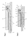
- FIG. 1 includes a pipe press fitting according to a first embodiment for connecting two multilayer composite pipes, of which only one pipe end 10 is shown schematically, a support sleeve 11 and two union ferrules 12, of which only one is shown.
- the pipe coupling can also be designed as an angle piece, reducer, T-piece, etc.
- FIG. 1 shown supporting sleeve 11 has a defined slight oversize compared to the nominal inner diameter of the pipe end 10 and is by means of a special tool from the right in FIG. 1 drawn into the pipe end 10 until the pipe end 10 abuts the front side on a circumferential around the support sleeve 11 stop flange 13. Subsequently, the previously pushed over the pipe end 10 union compression sleeve 12 with a defined inner diameter from the left in FIG.
- the support sleeve 11 has on its outer periphery a profiling 14, so that during the compression process with an application of radial compression forces on the union compression sleeve 12, the inner surface of the pipe end 10 is deformed according to the profiling 14 of the support sleeve 11 and axially fixed.
- the shear or tensile forces acting on the individual layers of the multilayer composite tube during the operation of the pipeline are optimally distributed, so that an undesirable separation of the layers of the multilayer composite pipe can be effectively avoided even in pipe systems with high mechanical stress.
- the risk is at least substantially reduced that outer layers of the multilayer composite pipe are torn off, while inner layers of the multilayer composite pipe remain on the support sleeve 11.
- the support sleeve 11 and the compression sleeve 12 are also designed to cooperate such that during axial sliding of the compression sleeve 12 locking between the union compression sleeve 12 and support sleeve 11 takes place, whereby the union compression sleeve 12 and the support sleeve 11 in the axial direction to each other be arrested.
- the latching takes place by means of a Federringverrastung, a radially encircling, radially outwardly opening annular groove 16 in the stop flange 13 of the support sleeve 11, a radially encircling, at the bottom of the annular groove 16 adjacent elastic O-ring 17, the cord thickness is a little smaller than the width the annular groove 16 is an outer ring around the O-ring 17 extending around the spring ring 18, whose width is a little smaller than the width of the annular groove 16 and with a part of its cross-section is still in the annular groove 16 which has a corresponding depth and an axial extension 19 at the front end of the compression sleeve 12 having a radially inwardly directed radially encircling nose 20 includes.
- the projection 19 and the nose 20 extend radially around the stop flange 13 in the installed state of the tube press coupling, wherein the nose 20 engages behind the spring ring 18, so that the union compression sleeve 12 engages the support sleeve 11 when pushed onto the tube end 10 becomes.
- the extension 19 and / or the nose 20 may be slotted in the axial direction, ie consist of individual sections which extend at intervals around the end face of the union compression sleeve 12.
- FIG. 1 shown in the compressed state thus contains a snap connection or Federringverrastung from the (optionally slotted) spring ring 18 and the adjoining thereto elastic O-ring 17 within the annular groove 16 in the stop flange 13 of the support sleeve 11.
- the spring ring 18 and the O-ring 17 are temporarily compressed, whereupon the spring ring 18 expands again until reaching its end position, whereby a locking between the union compression sleeve 12 and support sleeve 11 is achieved.
- Locking the union compression sleeve 12 shown by means of a spring ring can be provided in an analogous manner for locking a lying between the pipe end 10 and the compression sleeve 12 compression sleeve.
- annular groove 16 with O-ring and spring ring need not necessarily be formed on the support sleeve 11 or its stop flange 13, but a corresponding annular groove may also be formed in the counterpart to be locked, ie in the compression sleeve 12 and / or a ferrule , in which Case the od acting on the spring ring locking element in the form of a nose, a flatter annular groove od.
- a corresponding annular groove may also be formed in the counterpart to be locked, ie in the compression sleeve 12 and / or a ferrule , in which Case the od acting on the spring ring locking element in the form of a nose, a flatter annular groove od.
- Form on the support sleeve 11 would be.
- FIG. 2 in the reference numerals for opposite FIG. 1 analog components are each provided with a dash, shows a second embodiment of the invention, in which between the pipe end 10 'and union-compression sleeve 12' a ferrule 21 is provided, which is axially fixed as well as the union compression sleeve 12 ', but not through direct locking of the ferrule 21 with the support sleeve 11 '. Rather, there is a locking of the union-pressing sleeve 12 'with the support sleeve 11', and the ferrule 21 is then indirectly due to a positive connection with the union-pressing sleeve 12 'axially against the support sleeve 11' fixed.
- the ferrule 21 has its end flush with the pipe end 10 'has an annular on its outer circumferential stop flange 22.
- This stop flange 22 acts in the compressed state according to FIG. 2 with an abutment pressing sleeve 12 'formed stop surface 23 together such that the ferrule 21 is blocked against being pulled out of the union compression sleeve 12', whereby the ferrule 21 is in turn locked relative to the support sleeve 11 '.
- the throw-over compression sleeve 12 ' is analogous to the embodiment described above with a locking device 17', 18 ', 19', 20 'is provided, which secures the union compression sleeve 12' in the compressed state by Federringverrastung against the support sleeve 11 'axially.
- the pipe end 10 ' is thus effectively axially fixed both from the outside and from the inside.
- the fixation from the outside becomes even stronger by means of a profiling 24 in the form of a sharp-edged flat annular groove in the inner surface of the ferrule 21.
- the material of the pipe end 10 ' digs into the profiling 24, which - as a result of the deformation associated with the Verpressungsvorgang and the intervention caused thereby the outside of the pipe end 10 '- a relative movement between the outside of the pipe end 10' and the ferrule 21 additionally counteracts.
- the latching between the ferrule and the support sleeve can only be produced by the actual compression process and the deformation associated therewith, whereas in the unpressed state only the ferrule and support sleeve (without latching) slide along one another.
- a projection, a nose or the like may be provided which radially expands somewhat radially outwardly during the crimping operation as material compensation for the crimping operation taking place in the axially adjacent region of the crimping sleeve, whereby a fixation e.g. can be made with an undercut provided on the support sleeve.
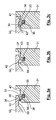
- FIGS. 3a to 3c are enlarged partial longitudinal sectional views of another embodiment of a Federringverrastung between a union compression sleeve 32 and a support sleeve 31 in different Montagestadien.
- This locking is both at the in FIG. 1 shown pipe compression coupling without ferrule and in the in FIG. 2 can be used with indirectly axially fixed ferrule shown.
- this latching - in duplicate - also for locking both the crimping and the compression sleeve in an embodiment according to FIG. 2 suitable.
- FIGS. 3a-c Similar to the basis of Figures 1 and 2 Federringverrastung described is the locking according to the FIGS. 3a-c formed by a (preferably slotted) spring ring 34 and an underlying elastomer or O-ring 33.
- the O-ring 33 is located in an annular groove 38 in the support sleeve 31 and a stop flange 13, 13 'in Figures 1 and 2 corresponding stop flange of the support sleeve 31 is formed.
- the union-pressing sleeve 32 has the front side a circumferential extension 35 with a latching nose defining undercut 39.
- the extension 35 does not have to be completely circumferential, but it is sufficient if it is provided in partial regions of the frontal circumference of the compression sleeve 32.
- sliding over the compression sleeve 32 shown slides the extension 35 on the spring ring 34 and compresses it when the extension 35 slides with a run-on slope 37 via the spring ring 34.
- the spring ring 34 is held centered and supported by the underlying O-ring 33, wherein the preferably formed of an elastomer O-ring 33 is compressed.
- the outer diameter of the support sleeve 31 relative to the smallest inner diameter of the compression sleeve 32 can be increased slightly, as in the FIGS. 3a-c dashed lines (not to scale) indicated at 42, whereas the areas 43 of the support sleeve 31 beyond the annular groove 38 have no enlarged diameter.
- the union compression sleeve 32 would therefore have to initially slightly expand when making the compression to overcome the region 42.
- the spring ring 34 is additionally locked in the situation shown in Figure 6c and thus held the union compression sleeve even safer.
- a corresponding increase in the diameter of the support sleeve is also in the embodiments according to Figures 1 and 2 possible.
- the arrangement has an additional means for ensuring the axial fixation of the compression sleeve.
- This is a section 36 (see Figure 6c) of the annular groove 38 in the support sleeve 31, which portion 36 is formed by a step on the annular groove 38, which - is arranged - in the direction of the pipe end - in front of the annular groove 38.
- the groove portion 36 is less deep than the major of the O-ring 33 filled main portion of the annular groove 38. The depth of the groove portion 36 is selected so that there only the spring ring 34 can be received therein, but not the underlying O-ring 33rd ,
- the spring ring 34 In the assembled state, the spring ring 34 is expanded due to the spring force of the O-ring 33. If in this state, an axial tensile force acts on the union compression sleeve 32, which could lead to a withdrawal of the same, the spring ring 34 is pulled with a part of its cross section in the groove portion 36, as shown in Figure 6c. In the groove portion 36, the spring ring 34 can no longer compress, because it rests on the step formed thereof, so that an axial withdrawal of the compression sleeve 32 is virtually impossible even with strong tensile forces.
- the spring ring 34 is preferably made of a spring steel and slotted formed.
- the width of the slot is adapted to the expected compression of the spring ring.
- the cross-sectional profile of the spring ring may also be non-circular, in particular rectangular or square, in embodiments not shown, which may even enhance the desired locking effect.
- Verrastungs Whit the advantage of very low forces for the production of locking - which is particularly relevant for pipe couplings with large pipe diameters - with extremely high blocking forces.
- a corresponding latching can alternatively or additionally also be carried out for the ferrule.
- the support sleeve and the crimping or crimping sleeves are each formed rotationally symmetrical, which od a cost-effective production by rotation.
- the support sleeve and the crimping or crimping sleeves are each formed rotationally symmetrical, which od a cost-effective production by rotation.
Landscapes
- Engineering & Computer Science (AREA)
- General Engineering & Computer Science (AREA)
- Mechanical Engineering (AREA)
- Quick-Acting Or Multi-Walled Pipe Joints (AREA)
Abstract
Description
Die vorliegende Erfindung betrifft eine Rohrpresskupplung, insbesondere zur Verpressung von Mehrschichtrohren, sowie ein Verfahren zum Anbringen einer Rohrpresskupplung an einem Rohrende.The present invention relates to a pipe press fitting, in particular for pressing multilayer pipes, and a method for attaching a pipe press fitting to a pipe end.
Bei Mehrschichtrohren handelt es sich um einen Rohrtypus für den Sanitär- und Heizungsbau sowie viele andere Anwendungen, der insbesondere in der Form des Mehrschichtverbundrohres mittlerweile häufige Verwendung findet. Mehrschichtverbundrohre sind typischerweise sandwichartig aus einer Mehrzahl von metallischen und nicht-metallischen - z.B. mittels Kleber sowie Haftvermittlern miteinander verbundenen - Schichten aufgebaut und finden insbesondere im Installationsbereich aufgrund ihrer vorteilhaften Eigenschaften, vor allem der vergleichsweise geringen Materialstärke, der hohen Sauerstoffdichtigkeit und der guten Verarbeitbarkeit (vor allem aufgrund der im Unterschied zu Mono-Kunststoffrohren bestehenden Möglichkeit, die Rohre bis zu einem gewissen Grade inelastisch zu biegen) zunehmende Verbreitung. Neben den Mehrschichtverbundrohren sind jedoch auch im Wesentlichen aus einem sortenreinen Kunststoff hergestellte Mehrschichtrohre bekannt, bei denen beispielsweise eine Schicht eine Faser- oder Eigenverstärkung bildet.Multi-layer pipes are a type of pipe for sanitary and heating construction as well as many other applications, which is now frequently used, particularly in the form of the multi-layer composite pipe. Multilayer composite pipes are typically sandwiched by a plurality of metallic and non-metallic - e.g. By means of adhesive and adhesion promoters interconnected - built layers and find especially in the installation area due to their advantageous properties, especially the comparatively low material thickness, high oxygen tightness and good processability (especially due to the existing in contrast to mono-plastic pipes, possibility to pipes to inelastically bend to a certain extent) increasing distribution. In addition to the multilayer composite pipes, however, multilayer pipes produced essentially from a single-grade plastic are also known, in which, for example, a layer forms a fiber or intrinsic reinforcement.
Eine Rohrpresskupplung zum Verbinden von Rohren miteinander ist aus der
Der vorliegenden Erfindung liegt die Aufgabe zu Grunde, die bekannte Rohrpresskupplung insbesondere im Hinblick auf die Anforderungen von Mehrschichtrohren zu verbessern.The present invention is based on the object to improve the known pipe coupling, in particular with regard to the requirements of multilayer pipes.
Diese Aufgabe wird bei einer Rohrpresskupplung mit oder ohne Quetschhülse und bei einem Verfahren gemäß den Oberbegriffen der Patentansprüche 1 und 9 durch die kennzeichnenden Merkmale dieser Ansprüche gelöst.This object is achieved in a pipe compression coupling with or without ferrule and in a method according to the preambles of claims 1 and 9 by the characterizing features of these claims.
Der Ring aus gummielastischem Material unterhalb des Federrings in der Ringnut lässt die Anforderungen an die Passgenauigkeit der Verrastungselemente erheblich sinken. Bisher bedurfte es insbesondere bei größeren Rohrdurchmessern und federringloser Arretierung einigen Aufwandes, die Verrastungselemente mit so kleinen Toleranzen auszubilden, dass einerseits die Überwurf-Presshülse an den Anschlagflansch geschoben werden konnte und andererseits eine zuverlässige Verrastung gewährleistet war. Mit der Erfindung ist gewährleistet, dass die Überwurf-Presshülse mit geringeren axialen Kräften aufgeschoben und arretiert werden kann, weil der Ring aus gummielastischem Material nachgibt, und dass die Verrastung sich dennoch nicht leicht löst, weil der Ring aus gummielastischem Material den Federring dauerhaft in einer Verriegelungsstellung hält.The ring of rubber-elastic material below the spring ring in the annular groove can drop the requirements on the accuracy of fit of Verrastungselemente significantly. Previously, it was necessary, especially for larger pipe diameters and feather-less locking some effort to form the Verrastungselemente with such small tolerances that on the one hand the union-pressing sleeve could be pushed to the stop flange and on the other hand, a reliable locking was guaranteed. With the invention it is ensured that the union compression sleeve can be pushed and locked with lower axial forces, because the ring yields from rubber-elastic material, and that the latch still does not solve easily, because the ring of rubber-elastic material permanently in a spring ring Locking position holds.
Bei der erfindungsgemäßen Rohrpresskupplung (auch als "Fitting" bezeichnet) kann es sich um ein Winkelstück, ein T-Stück, ein Reduzierstück od. dgl. handeln. Am anderen (in den Figuren nicht dargestellten) Ende des Fittings kann sich eine (spiegelbildlich ausgebildete) gleich große, kleinere oder größere Rohrpresskupplung, ein Schraubgewinde oder irgendein anderes Anschlussstück befinden.The pipe press coupling according to the invention (also referred to as "fitting") may be an elbow, a T-piece, a reducer or the like. At the other (not shown in the figures) end of the fitting may be a (mirror-image) equal sized, smaller or larger pipe coupling, a screw thread or any other connector.
Der Ring aus gummielastischem Material ist vorzugsweise ein elastomerer O-Ring, kann aber auch aus irgendeinem anderen gummielastischen Voll- oder Hohlmaterial bestehen und/oder irgendeinen anderen der Komprimierbarkeit förderlichen Querschnitt haben. Bei dem Ring aus gummielastischem Material muss es sich nicht um einen abnehmbaren geschlossenen Ring handeln, sondern es ist auch möglich, dass irgendein gummielastisches Material durch Formspritzen in die Ringnut eingebracht wird, was auch abschnittsweise geschehen kann.The ring of elastomeric material is preferably an elastomeric O-ring, but may also be made of any other elastomeric solid or hollow material and / or have any other compressibility-promoting cross-section. The ring of rubber-elastic material need not be a removable closed ring, but it is also possible that any rubber-elastic material is introduced by injection molding in the annular groove, which can also be done in sections.
Das mit dem Federring in der Ringnut zusammenwirkende Verrastungsmittel an der zu verrastenden Hülse kann eine weitere Ringnut sein, wie in der
Eine erfindungsgemäße Rastverbindung wird vorzugsweise zur Verbindung einer Überwurf-Presshülse mit einer Stützhülse verwendet. Wird zusätzlich eine Quetschhülse zwischen der Überwurf-Presshülse und dem Rohrende vorgesehen, so ist es vorteilhaft, die Quetschhülse mittels einer an der Überwurf-Presshülse vorgesehenen ringförmigen Anschlagfläche im verpressten Zustand gegenüber der durch die Rastverbindung axial arretierten Überwurf-Presshülse axial zu fixieren. Alternativ oder zusätzlich kann so eine Quetschhülse mittels einer eigenen Federringverrastung an der Stützhülse arretiert werden.A latching connection according to the invention is preferably used for connecting a compression sleeve with a support sleeve. If, in addition, a ferrule is provided between the union compression sleeve and the tube end, it is advantageous to axially fix the compression sleeve by means of an annular stop surface provided in the compression sleeve in the compressed state with respect to the coupling sleeve axially locked by the snap connection. Alternatively or additionally, such a ferrule can be locked by means of a separate Federringverrastung on the support sleeve.
Die den Federring aufnehmende(n) Ringnut(en) ist bzw. sind vorzugsweise in der Stützhülse und insbesondere in einem Anschlagflansch der Stützhülse, welcher vorzugsweise auf diese aufgeschraubt oder aufgepresst wird, ausgebildet, doch können diese auch an der Überwurf-Presshülse und/oder einer ggf. vorgesehenen Quetschhülse ausgebildet sein, in welchem Fall die Federringverrastung als im Querschnitt umgekehrt angeordnet anzusehen ist.The annular groove (s) receiving the spring ring is or are preferably formed in the support sleeve and in particular in a stop flange of the support sleeve, which is preferably screwed or pressed onto it, but these can also be attached to the compression sleeve and / or a possibly provided pinch sleeve may be formed, in which case the Federringverrastung is considered to be reversed arranged in cross section.
Eine besonders zuverlässige, durch Zugkräfte praktisch nicht lösbare Verrastung kann dadurch erzielt werden, dass die Ringnut im Querschnitt gestuft ausgebildet ist, derart, dass ein erster axialer Abschnitt der Ringnut den O-Ring im Wesentlichen vollständig aufnimmt, und dass ein in Verrastungsrichtung axial vor ersten Abschnitt liegender zweiter Abschnitt der Ringnut weniger tief als der erste axiale Abschnitt ist, vorzugsweise ungefähr um die Dicke des O-Rings weniger tief als der erste axiale Abschnitt der Ringnut ist. Dadurch kann der Federring bei verrasteter Rohrpresskupplung zumindest mit einem Teil seines Querschnitts in den zweiten Abschnitt hinein verschoben werden, so dass dieser mit seiner Innenseite auf der durch den zweiten Abschnitt der Ringnut gebildeten Stufe aufliegt und somit nicht mehr komprimierbar ist.A particularly reliable latching, which can not be released by pulling forces, can be achieved in that the annular groove has a stepped cross-section is, such that a first axial portion of the annular groove substantially completely accommodates the O-ring, and in that a second portion of the annular groove axially in the latching direction before the first portion is less deep than the first axial portion, preferably approximately to the thickness of the O Rings less deep than the first axial section of the annular groove. As a result, the spring ring can be displaced into the second section at least with a part of its cross section in the locked tube press-fit coupling, so that its inner side rests on the step formed by the second section of the annular groove and is therefore no longer compressible.
Im Falle, dass die Rohrpresskupplung auch eine Quetschhülse enthält, wird durch eine entweder direkt oder mit Hilfe der Überwurf-Presshülse mit der Stützhülse verrastete und somit axial arretierte Quetschhülse erreicht, dass die während des Betriebes der Rohrleitung auf die einzelnen Schichten des Mehrschichtrohres wirkenden Scher- bzw. Zugkräfte wesentlich besser von der Quetschhülse auf die Stützhülse abgeleitet werden können, so dass auch bei Rohrsystemen mit hoher mechanischer Belastung eine unerwünschte Trennung der Schichten des Mehrschichtrohres wirksam vermieden werden kann. Insbesondere wird die Gefahr zumindest wesentlich gemindert, dass Außenschichten des Mehrschichtrohres abgerissen werden, während Innenschichten des Mehrschichtrohres auf der Stützhülse verbleiben. Somit wird eine Fixierung des zu verbindenden Rohrendes nicht nur innenseitig erreicht (über eine ggf. am Außenumfang der Stützhülse vorhandene Profilierung), sondern auch außenseitig, d.h. an der Außenschicht des Mehrschichtrohres.In the event that the pipe press coupling also contains a ferrule, is achieved by a either directly or with the help of the compression sleeve with the support sleeve latched and thus axially locked ferrule that during operation of the pipeline acting on the individual layers of the multilayer pipe shear or tensile forces can be much better derived from the ferrule on the support sleeve, so that even in piping systems with high mechanical stress undesirable separation of the layers of the multilayer pipe can be effectively avoided. In particular, the risk is at least substantially reduced that outer layers of the multilayer tube are demolished, while inner layers of the multilayer tube remain on the support sleeve. Thus, a fixation of the pipe end to be joined is achieved not only on the inside (via an optionally existing on the outer circumference of the support sleeve profiling), but also on the outside, i. on the outer layer of the multilayer pipe.
Wenngleich die Erfindung vor allem in Verbindung mit Mehrschichtrohren, insbesondere Mehrschichtverbundrohren, vorteilhaft realisierbar ist, ist die Erfindung nicht auf Mehrschichtrohre beschränkt. Vielmehr kann die Erfindung auch in Verbindung mit beliebigen anderen Rohrtypen, z.B. gewebe- oder eigenverstärkten Rohren, welche eine wesentliche Steigerung der Druckfestigkeit ermöglichen, oder in Verbindung mit Kunststoffrohren, Kupferrohren oder Stahlrohren verwendet werden.Although the invention can be advantageously implemented, especially in connection with multilayer pipes, in particular multilayer composite pipes, the invention is not limited to multilayer pipes. Rather, the invention can also be used in conjunction with any other types of tubes, such as woven or self-reinforced tubes, which allow a substantial increase in compressive strength, or in conjunction with plastic pipes, copper pipes or steel pipes.
Zusammengefasst wird gemäß der Erfindung das Verrasten zumindest teilweise durch einen während des axialen Aufschiebens der Überwurf-Presshülse vorübergehend komprimierten, durch den Elastomer-Ring zentriert gehaltenen und ggf. geschlitzten Federring bewirkt, der im verpressten Zustand der Rohrpresskupplung zwischen der Überwurf-Presshülse und der Stützhülse und/oder zwischen der Quetschhülse und der Stützhülse angeordnet ist und durch den Elastomer-Ring dauerhaft in der Verriegelungsstellung gehalten wird. Dies hat insbesondere bei größeren Rohrdurchmessern den Vorteil, dass die zur Erzielung der Verrastung der Stützhülse mit der Überwurf-Presshülse und/oder der Quetschhülse erforderlichen Kräfte reduziert werden können und dass die Anforderungen an die Passgenauigkeit der Kupplungsteile sinken.In summary, according to the invention, the latching is effected at least partially by a temporarily compressed during the axial sliding of the compression sleeve, held centered by the elastomeric ring and possibly slotted spring ring in the compressed state of the pipe coupling between the compression sleeve and the support sleeve and / or between the ferrule and the support sleeve and is held by the elastomeric ring permanently in the locking position. This has the advantage, in particular with larger pipe diameters, that the forces required to achieve the locking of the support sleeve with the compression sleeve and / or the ferrule can be reduced and that the requirements for the accuracy of fit of the coupling parts decrease.
Weitere vorteilhafte Ausgestaltungen der Erfindung sind der Beschreibung sowie den Unteransprüchen zu entnehmen.Further advantageous embodiments of the invention are described in the description and the dependent claims.
Die Erfindung wird nachstehend anhand bevorzugter Ausführungsformen und unter Bezugnahme auf die beigefügten Abbildungen näher erläutert.The invention is explained below with reference to preferred embodiments and with reference to the accompanying drawings.
Es zeigen:
- Figur 1
- einen Teil-Längsschnitt durch eine mit einer Federringverras- tung versehene Rohrpresskupplung ohne Quetschhülse im Zustand nach der Verpressung (d.h. im verpressten oder mon- tierten Zustand);
- Figur 2
- einen Teil-Längsschnitt durch eine mit einer Federring- verrastung versehene Rohrpresskupplung mit Quetschhülse im verpressten Zustand; und
- Figuren 3a-c
- Detaildarstellungen einer alternativen Ausführungsform einer Federringverrastung einer Rohrpresskupplung in verschiede- nen Montagestadien.
- FIG. 1
- a partial longitudinal section through a provided with a Federringverras- tion pipe press fitting without ferrule in the state after compression (ie in the compressed or mounted state);
- FIG. 2
- a partial longitudinal section through a provided with a Federring- latching tube press fitting with ferrule in the compressed state; and
- FIGS. 3a-c
- Detailed representations of an alternative embodiment of a Federringverrastung a pipe coupling in various assembly stages.
Gemäß
Die in
Die Stützhülse 11 weist an ihrem Außenumfang eine Profilierung 14 auf, so dass während des Verpressungsvorgangs bei einem Aufbringen radialer Verpresskräfte auf die Überwurf-Presshülse 12 die Innenfläche des Rohrendes 10 entsprechend der Profilierung 14 der Stützhülse 11 verformt und axial fixiert wird.The
Am Ende des Verpressvorgangs gräbt sich außerdem eine Kante 15, die durch eine radial umlaufende Stufe in der Innenfläche der Überwurf-Presshülse 12 gebildet wird, in den Außenumfang des hier bereits aufgeweiteten Rohrendes 10 ein, so dass auch die Außenfläche des Rohrendes 10 axial fixiert wird.At the end of the pressing process also digs an
Durch das beidseitige Verformen des Rohrendes 10 bzw. das Eingraben darin werden die während des Betriebes der Rohrleitung auf die einzelnen Schichten des Mehrschichtverbundrohres wirkenden Scher- bzw. Zugkräfte optimal verteilt, so dass auch bei Rohrsystemen mit hoher mechanischer Belastung eine unerwünschte Trennung der Schichten des Mehrschichtverbundrohres wirksam vermieden werden kann. Insbesondere wird die Gefahr zumindest wesentlich gemindert, dass Außenschichten des Mehrschichtverbundrohres abgerissen werden, während Innenschichten des Mehrschichtverbundrohres auf der Stützhülse 11 verbleiben.Due to the double-sided deformation of the
Die Stützhülse 11 und die Überwurf-Presshülse 12 sind außerdem derart zusammenwirkend ausgebildet, dass beim axialen Aufschieben der Überwurf-Presshülse 12 ein Verrasten zwischen Überwurf-Presshülse 12 und Stützhülse 11 erfolgt, wodurch die Überwurf-Presshülse 12 und die Stützhülse 11 in axialer Richtung zueinander arretiert werden.The
Das Verrasten erfolgt mittels einer Federringverrastung, die eine radial umlaufende, sich radial nach außen öffnende Ringnut 16 im Anschlagflansch 13 der Stützhülse 11, einen radial umlaufenden, am Boden der Ringnut 16 anliegenden elastischen O-Ring 17, dessen Schnurstärke ein wenig kleiner als die Breite der Ringnut 16 ist, einen außen um den O-Ring 17 herum verlaufenden Federring 18, dessen Breite ein wenig kleiner als die Breite der Ringnut 16 ist und der mit einem Teil seines Querschnitts noch in der Ringnut 16 liegt, die eine entsprechende Tiefe hat, und einen axialen Fortsatz 19 am stirnseitigen Ende der Überwurf-Presshülse 12 mit einer radial nach innen gerichteten radial umlaufenden Nase 20 umfasst.The latching takes place by means of a Federringverrastung, a radially encircling, radially outwardly opening
Der Fortsatz 19 und die Nase 20 erstrecken sich im montierten Zustand der Rohrpresskupplung radial um den Anschlagflansch 13 herum, wobei die Nase 20 den Federring 18 hintergreift, so dass die Überwurf-Presshülse 12 auf der Stützhülse 11 einrastet, wenn sie auf das Rohrende 10 aufgeschoben wird.The
Der Fortsatz 19 und/oder die Nase 20 können in axialer Richtung geschlitzt sein, d.h. aus einzelnen Abschnitten bestehen, die sich in Abständen rings um die Stirnseite der Überwurf-Presshülse 12 erstrecken.The
Das vorübergehende Komprimieren des Federrings 18 beim Aufschieben der Überwurf-Presshülse 12 wird durch eine stirnseitige Anlaufschräge an der Nase 20 erleichtert.The temporary compression of the
Beim Aufschieben der Überwurf-Presshülse 12 auf das Rohrende 10 wird der Federring 18 durch den O-Ring 17 zentriert gehalten, so dass er im Wesentlichen überall gleichzeitig einrastet, wodurch beim Verrasten der Rohrpresskupplung ein definiertes Einrastgeräusch erzeugt wird, das dem Monteur anzeigt, dass die Überwurf-Presshülse 12 korrekt eingerastet ist.When sliding the
Die in
Die in
Die Ringnut 16 mit O-Ring und Federring muss nicht notwendigerweise an der Stützhülse 11 bzw. deren Anschlagflansch 13 ausgebildet sein, sondern eine entsprechende Ringnut kann auch in dem zu arretierenden Gegenstück ausgebildet sein, d.h. in der Überwurf-Presshülse 12 und/oder einer Quetschhülse, in welchem Falle das am Federring angreifende Arretierelement in Form einer Nase, einer flacheren Ringnut od. dgl. an der Stützhülse 11 auszubilden wäre.The
Die
Die Quetschhülse 21 weist ihrem mit dem Rohrende 10' bündigen Ende einen auf ihrer Außenseite ringförmig umlaufenden Anschlagflansch 22 auf. Dieser Anschlagflansch 22 wirkt im verpressten Zustand gemäß
Die Überwurf-Presshülse 12' ist analog zu der vorstehend beschriebenen Ausführungsform mit einer Rasteinrichtung 17', 18', 19', 20' versehen, die die Überwurf-Presshülse 12' im verpressten Zustand durch Federringverrastung gegenüber der Stützhülse 11' axial sichert.The throw-over compression sleeve 12 'is analogous to the embodiment described above with a locking device 17', 18 ', 19', 20 'is provided, which secures the union compression sleeve 12' in the compressed state by Federringverrastung against the support sleeve 11 'axially.
Im Ergebnis ist das Rohrende 10' somit wirksam sowohl von der Außenseite her als auch von der Innenseite her axial fixiert. Die Fixierung von der Außenseite her wird noch fester mittels einer Profilierung 24 in Form einer scharfkantigen flachen Ringnut in der Innenfläche der Quetschhülse 21. Das Material des Rohrendes 10' gräbt sich in die Profilierung 24 ein, was - als Resultat der mit dem Verpressungsvorgang einhergehenden Verformung und des hierdurch bewirkten Eingriffs mit der Außenseite des Rohrendes 10' - einer Relativbewegung zwischen der Außenseite des Rohrendes 10' und der Quetschhülse 21 zusätzlich entgegenwirkt.As a result, the pipe end 10 'is thus effectively axially fixed both from the outside and from the inside. The fixation from the outside becomes even stronger by means of a
Wenngleich bei dem in
Vielmehr kann gemäß einer weiteren (nicht dargestellten) Ausführungsform die Verrastung zwischen Quetschhülse und Stützhülse erst durch den eigentlichen Verpressungsvorgang und die damit einhergehende Deformation hergestellt werden, wohingegen im unverpressten Zustand lediglich Quetschhülse und Stützhülse (ohne Verrastung) aneinander entlang gleiten. Hierzu kann an der Quetschhülse z.B. ein Vorsprung, eine Nase oder dergleichen vorgesehen sein, welche(r) während des Verpressungsvorganges als Materialausgleich für den im axial benachbarten Bereich der Quetschhülse stattfindenden Quetschvorgang radial etwas nach außen expandiert, wodurch eine Fixierung z.B. mit einem an der Stützhülse vorgesehenen Hinterschnitt hergestellt werden kann.Rather, according to another embodiment (not shown), the latching between the ferrule and the support sleeve can only be produced by the actual compression process and the deformation associated therewith, whereas in the unpressed state only the ferrule and support sleeve (without latching) slide along one another. For this purpose, at the ferrule, e.g. a projection, a nose or the like may be provided which radially expands somewhat radially outwardly during the crimping operation as material compensation for the crimping operation taking place in the axially adjacent region of the crimping sleeve, whereby a fixation e.g. can be made with an undercut provided on the support sleeve.
Die
Ähnlich der anhand von
Der O-Ring 33 liegt in einer Ringnut 38, die in der Stützhülse 31 bzw. einem dem Anschlagflansch 13, 13' in
Die Überwurf-Presshülse 32 weist stirnseitig einen umlaufenden Fortsatz 35 mit einem eine Rastnase definierenden Hinterschnitt 39 auf. Der Fortsatz 35 muss nicht vollständig umlaufend sein, sondern es genügt, wenn er in Teilbereichen des stirnseitigen Umfangs der Überwurf-Presshülse 32 vorgesehen ist. Bei dem in den
Wie weiterhin in den
Wird nach Herstellung der Verpressung eine verstärkte axiale Zugkraft zwischen Überwurf-Presshülse 32 und Stützhülse 31 aufgebracht, so weist die Anordnung, wie aus Figur 6c ersichtlich, ein zusätzliches Mittel zur Sicherstellung der axialen Fixierung der Presshülse auf. Dabei handelt es sich um einen Abschnitt 36 (siehe Figur 6c) der Ringnut 38 in der Stützhülse 31, welcher Abschnitt 36 durch eine Stufe an der Ringnut 38 gebildet wird, die - in Richtung auf das Rohrende - vor der Ringnut 38 angeordnet ist. Der Nutabschnitt 36 ist weniger tief als der Wesentlichen von dem O-Ring 33 ausgefüllte Hauptabschnitt der Ringnut 38. Die Tiefe des Nutabschnitts 36 ist so gewählt, dass dort nur der Federring 34 darin aufgenommen werden kann, nicht jedoch der darunter liegende O-Ring 33.If, after the production of the compression, an increased axial tensile force is applied between the
Im montierten Zustand, ist der Federring 34 aufgrund der Federkraft des O-Rings 33 expandiert. Wenn in diesem Zustand eine axiale Zugkraft auf die Überwurf-Presshülse 32 wirkt, die zu einem Abziehen derselben führen könnte, wird der Federring 34 mit einem Teil seines Querschnitts in den Nutabschnitt 36 gezogen, wie in Figur 6c gezeigt. Im Nutabschnitt 36 kann sich der Federring 34 nicht mehr komprimieren, weil er auf der davon gebildeten Stufe aufliegt, so dass ein axiales Abziehen der Überwurf-Presshülse 32 auch bei starken Zugkräften praktisch unmöglich ist.In the assembled state, the
Der Federring 34 ist bevorzugt aus einem Federstahl hergestellt und geschlitzt ausgebildet. Die Breite des Schlitzes ist an die zu erwartenden Komprimierungen des Federrings angepasst. Ferner ist es auch denkbar, einen geschlitzten Federring zu verwenden, bei dem sich die Enden überlappen. Das Querschnittsprofil des Federrings kann in nicht dargestellten Ausführungsformen auch unrund, insbesondere rechteckig oder quadratisch ausgebildet sein, was die gewünschte Arretierwirkung sogar noch verstärken kann.The
Auf diese Weise verbindet das vorbeschriebene Verrastungskonzept den Vorteil sehr geringer Kräfte für die Herstellung der Verrastung - was insbesondere bei Rohrpresskupplungen mit großen Rohrdurchmessern relevant ist - mit extrem hohen Blockierungskräften. Wie bereits erwähnt, kann eine entsprechende Verrastung alternativ oder zusätzlich auch für die Quetschhülse erfolgen.In this way, the above-described Verrastungskonzept the advantage of very low forces for the production of locking - which is particularly relevant for pipe couplings with large pipe diameters - with extremely high blocking forces. As already mentioned, a corresponding latching can alternatively or additionally also be carried out for the ferrule.
Weiterhin ist an dem vorstehend dargestellten Verrastungskonzept vorteilhaft, dass die Stützhülse und die Press- bzw. Quetschhülsen jeweils rotationssymmetrisch ausgebildet sind, was eine kostengünstige Herstellung durch Drehen od. dgl. ermöglicht.Furthermore, it is advantageous on the Verrastungskonzept shown above, that the support sleeve and the crimping or crimping sleeves are each formed rotationally symmetrical, which od a cost-effective production by rotation. Like. Enables.
Die vorstehend beschriebenen und dargestellten Arretierungsarten können auch zur Arretierung der Presshülsen von Rohrpresskupplungen gemäß allen Ausführungsformen der
Claims (14)
dadurch gekennzeichnet, dass
in der mindestens einen Ringnut (16; 16'; 38) ein Ring (17; 17'; 33) aus gummielastischem Material angeordnet ist, der den Federring (18; 18'; 34) vom Boden der Ringnut trennt.Pipe press coupling, in particular for pressing multilayer pipes, in particular multi-layer composite pipes, with a suitable in a pipe end (10; 10 ') support sleeve (11; 11'; 31), either directly or with the interposition of a ferrule (21) on the pipe end fitting union -Presshülse (12; 12 ', 32) and Verrastungsmitteln for fixing the compression sleeve and / or the ferrule in the axial direction relative to the support sleeve, wherein the latching means at least one radially encircling annular groove (16; 16', 38) on one of the sleeves (11; 11 ';31;12;12';32; 21) and a spring ring (18; 18 '; 34) accommodated in the at least one annular groove,
characterized in that
in the at least one annular groove (16; 16 '; 38) a ring (17; 17'; 33) of rubber-elastic material is arranged, which separates the spring ring (18; 18 '; 34) from the bottom of the annular groove.
dadurch gekennzeichnet, dass
der Ring (17; 17'; 33) aus gummielastischem Material dahingehend angeordnet ist, dass dieser den Federring (18; 18'; 34) zentriert.Pipe compression coupling according to claim 1,
characterized in that
the ring (17; 17 '; 33) of elastomeric material is arranged to center the spring ring (18; 18'; 34).
dadurch gekennzeichnet, dass
der Ring (17; 17'; 33) aus gummielastischem Material ein O-Ring ist.Pipe compression coupling according to claim 1 or 2,
characterized in that
the ring (17; 17 '; 33) of elastomeric material is an O-ring.
dadurch gekennzeichnet, dass
der Federring einen kreisförmigen oder einen vieleckigen, insbesondere rechteckigen, Querschnitt aufweist.Pipe compression coupling according to one of claims 1 to 3,
characterized in that
the spring ring has a circular or a polygonal, in particular rectangular, cross-section.
dadurch gekennzeichnet, dass
die Verrastungsmittel zur Fixierung der Überwurf-Presshülse (12; 12', 32) relativ zur Stützhülse (11; 11'; 31) dienen und dass die den Federring (18; 18'; 34) aufnehmende Ringnut (16; 16'; 38) an der Stützhülse ausgebildet ist.Pipe compression coupling according to one of claims 1 to 4,
characterized in that
the latching means for fixing the union-pressing sleeve (12, 12 ', 32) relative to the support sleeve (11, 11', 31) serve and that the spring ring (18, 18 ', 34) receiving annular groove (16, 16', 38 ) is formed on the support sleeve.
dadurch gekennzeichnet, dass
zwischen der Überwurf-Presshülse (12; 12', 32) und dem Rohrende (10; 10') eine Quetschhülse (21) vorgesehen ist, die mittels einer an der Überwurf-Presshülse vorgesehenen ringförmigen Anschlagfläche (23) im verpressten Zustand gegenüber der Überwurf-Presshülse axial fixiert ist.Pipe compression coupling according to one of claims 1 to 5,
characterized in that
between the union-pressing sleeve (12, 12 ', 32) and the tube end (10, 10') a ferrule (21) is provided which by means of an annular compression surface provided on the sleeve (23) in the compressed state against the cap -Presshülse is axially fixed.
dadurch gekennzeichnet, dass
die Stützhülse (11; 11'; 31) zweiteilig mit einem aufgeschraubtem Anschlagflansch (13; 13') ausgebildet ist.Pipe compression coupling according to one of the preceding claims,
characterized in that
the support sleeve (11; 11 '; 31) is formed in two parts with a stop flange (13; 13') screwed on.
dadurch gekennzeichnet, dass
die Stützhülse (11; 11'; 31) einen radial äußeren Anschlagflansch (13; 13') für das Rohrende (10; 10') aufweist, in dem die mindestens eine, den Ring (17; 17'; 33) aus gummielastischem Material und den Federring (18; 18'; 34) aufnehmende Ringnut (16; 16'; 38) ausgebildet ist, so dass sie sich radial nach außen öffnet, und dass die Überwurf-Presshülse (12; 12', 32) mindestens einen axialen Fortsatz (19; 19'; 35) mit mindestens einer radial nach innen gerichteten Nase (20; 20') aufweist, wobei bei axialem Aufschieben der Überwurf-Presshülse auf die Stützhülse der mindestens eine Fortsatz über den Anschlagflansch gelangt und die mindestens eine Nase den Federring hintergreift, so dass die Überwurf-Presshülse auf der Stützhülse einrastet.Pipe compression coupling according to one of the preceding claims,
characterized in that
the support sleeve (11; 11 '; 31) has a radially outer stop flange (13; 13') for the tube end (10; 10 ') in which the at least one ring (17; 17'; 33) is made of rubber-elastic material and the spring ring (18; 18 '; 34) receiving annular groove (16; 16'; 38) is formed so that it opens radially outward, and that the union compression sleeve (12; 12 ', 32) at least one axial An extension (19, 19 ', 35) having at least one radially inwardly directed lug (20, 20'), wherein when the push-on sleeve is pushed axially onto the support sleeve, the at least one extension passes over the stop flange and the at least one nose engages behind the spring ring, so that the union compression sleeve engages on the support sleeve.
dadurch gekennzeichnet, dass
der axiale Fortsatz (19; 19'; 35) bzw. dessen Nase (20; 20') eine Anlaufschräge (37) für den Federring (18; 18'; 34) aufweist, an welcher Anlaufschräge der Federring und das darunter liegende gummielastische Material beim Verrasten der Rohrpresskupplung radial komprimiert werden, bevor sie wieder expandieren und dadurch der Federring hinter der Nase einrastet.Pipe compression coupling according to claim 8,
characterized in that
The axial extension (19, 19 ', 35) or its nose (20, 20') has a run-on slope (37) for the spring ring (18, 18 ', 34), at which run-on slope the spring washer and the rubber-elastic material underneath be compressed radially when locking the pipe coupling before they expand again and thereby the spring ring snaps behind the nose.
dadurch gekennzeichnet, dass
die mindestens eine Ringnut (38) im Querschnitt gestuft ist, derart, dass ein erster axialer Abschnitt der Ringnut den Ring (33) aus gummielastischem Material im Wesentlichen vollständig aufnimmt und dass ein in Verrastungsrichtung axial vor ersten Abschnitt liegender zweiter axialer Abschnitt (36) der Ringnut weniger tief als der erste axiale Abschnitt ist.Pipe compression coupling according to one of the preceding claims,
characterized in that
the at least one annular groove (38) is stepped in cross-section, such that a first axial section of the annular groove substantially completely accommodates the ring (33) of rubber-elastic material and that a second axial section (36) lying axially in front of the first latching section Ring groove is less deep than the first axial section.
dadurch gekennzeichnet, dass
die zweite axiale Abschnitt (36) der Ringnut (38) ungefähr um die Dicke des Rings (33) aus gummielastischem Material weniger tief als der erste axiale Abschnitt der Ringnut ist.Pipe compression coupling according to claim 10,
characterized in that
the second axial portion (36) of the annular groove (38) is less deep than the first axial portion of the annular groove by approximately the thickness of the ring (33) of elastomeric material.
dadurch gekennzeichnet, dass
vor dem Einlegen des Federrings (18; 18'; 34) ein Ring (17; 17'; 33) aus gummielastischem Material in die Ringnut (16; 16'; 38) eingebracht wird, welches gummielastische Material den Federring tendenziell in einem Abstand vom Boden der Ringnut hält.A method for attaching a pipe press fitting to a pipe end (10, 10 '), in particular a multilayer pipe, in particular a multi-layer composite pipe, wherein in the pipe end, a support sleeve (11, 11', 31) is used, optionally on the pipe end a ferrule (21) is arranged and then a union compression sleeve (12, 12 ', 32) is pushed onto the pipe end or the ferrule, whereby or after which a compression of the pipe coupling takes place, wherein the union compression sleeve and / or the ferrule by means of a in an annular groove (16 16 ', 38) inserted spring ring (18, 18', 34) locked to the support sleeve,
characterized in that
before inserting the spring ring (18, 18 '; 34) a ring (17; 17'; 33) made of rubber-elastic material in the annular groove (16; 16 '; 38) is introduced, which rubber elastic material tends to the spring ring at a distance from Bottom of the ring groove stops.
dadurch gekennzeichnet, dass
der Ring (17; 17'; 33) aus gummielastischem Material den Federring zentriert.Method according to claim 12,
characterized in that
the ring (17; 17 '; 33) of rubber-elastic material centers the spring washer.
dadurch gekennzeichnet, dass
die Rohrpresskupplung gemäß einem der Ansprüche 1 bis 11 ausbildet ist.Method according to claim 12 or 13,
characterized in that
the pipe compression coupling according to one of claims 1 to 11 is formed.
Priority Applications (1)
| Application Number | Priority Date | Filing Date | Title |
|---|---|---|---|
| PL10187401T PL2322831T3 (en) | 2009-11-12 | 2010-10-13 | Pipe press coupling, in particular for swaging multi-layer tubing and method for applying a pipe press coupling |
Applications Claiming Priority (1)
| Application Number | Priority Date | Filing Date | Title |
|---|---|---|---|
| DE102009044500 | 2009-11-12 |
Publications (2)
| Publication Number | Publication Date |
|---|---|
| EP2322831A1 true EP2322831A1 (en) | 2011-05-18 |
| EP2322831B1 EP2322831B1 (en) | 2013-05-29 |
Family
ID=43530171
Family Applications (1)
| Application Number | Title | Priority Date | Filing Date |
|---|---|---|---|
| EP10187401.4A Active EP2322831B1 (en) | 2009-11-12 | 2010-10-13 | Pipe press coupling, in particular for swaging multi-layer tubing and method for applying a pipe press coupling |
Country Status (4)
| Country | Link |
|---|---|
| EP (1) | EP2322831B1 (en) |
| DE (1) | DE102010038170A1 (en) |
| DK (1) | DK2322831T3 (en) |
| PL (1) | PL2322831T3 (en) |
Cited By (3)
| Publication number | Priority date | Publication date | Assignee | Title |
|---|---|---|---|---|
| EP2775187A3 (en) * | 2013-03-07 | 2014-10-29 | Grohe AG | Device for a hose fitting |
| WO2015181002A1 (en) | 2014-05-28 | 2015-12-03 | Daniel Knipping | Sliding-compression ring/tool part for connecting pipes |
| DE102019118588A1 (en) * | 2019-07-09 | 2021-01-14 | Daniel Knipping | Crimp sleeve for pipe connections |
Families Citing this family (5)
| Publication number | Priority date | Publication date | Assignee | Title |
|---|---|---|---|---|
| DE102017005028A1 (en) | 2017-05-26 | 2018-11-29 | Eugen Riexinger GmbH & Co. KG, Plasticconnectingsystems | Coupling for producing a press connection between two pipes |
| JP6798713B2 (en) * | 2019-02-12 | 2020-12-09 | 株式会社トヨックス | Pipe fitting |
| DE202019104502U1 (en) * | 2019-08-15 | 2020-11-23 | Rehau Ag + Co | Connection element assembled with a crimp sleeve as well as pipe connection encompassing this |
| DE102021106229A1 (en) | 2020-12-17 | 2022-06-23 | REHAU Industries SE & Co. KG | Connecting element system for producing a pipe connection, pipe connection comprising this, and method for producing such a pipe connection |
| US12025255B2 (en) | 2021-04-23 | 2024-07-02 | Eaton Intelligent Power Limited | Quick action fluid coupler |
Citations (5)
| Publication number | Priority date | Publication date | Assignee | Title |
|---|---|---|---|---|
| GB926215A (en) * | 1960-11-09 | 1963-05-15 | Rollmaplast Ag | Disengageable pipe coupling |
| EP0477704B1 (en) | 1990-09-25 | 1997-07-23 | Daniel Knipping | Contracted pipecoupling |
| EP1273843A1 (en) * | 2001-07-02 | 2003-01-08 | Geci | Reusable coupling for connecting the ends of a reinforced hose |
| DE102004003426B3 (en) * | 2004-01-23 | 2005-05-04 | Daimlerchrysler Ag | Connection for fluid lines is in insertion form and has connecting piece with locking ring |
| DE202008006797U1 (en) * | 2008-05-20 | 2008-07-24 | Mainhart, Patrick | Press sleeve attachment to a fitting body |
-
2010
- 2010-10-13 DE DE102010038170A patent/DE102010038170A1/en not_active Withdrawn
- 2010-10-13 PL PL10187401T patent/PL2322831T3/en unknown
- 2010-10-13 DK DK10187401.4T patent/DK2322831T3/en active
- 2010-10-13 EP EP10187401.4A patent/EP2322831B1/en active Active
Patent Citations (5)
| Publication number | Priority date | Publication date | Assignee | Title |
|---|---|---|---|---|
| GB926215A (en) * | 1960-11-09 | 1963-05-15 | Rollmaplast Ag | Disengageable pipe coupling |
| EP0477704B1 (en) | 1990-09-25 | 1997-07-23 | Daniel Knipping | Contracted pipecoupling |
| EP1273843A1 (en) * | 2001-07-02 | 2003-01-08 | Geci | Reusable coupling for connecting the ends of a reinforced hose |
| DE102004003426B3 (en) * | 2004-01-23 | 2005-05-04 | Daimlerchrysler Ag | Connection for fluid lines is in insertion form and has connecting piece with locking ring |
| DE202008006797U1 (en) * | 2008-05-20 | 2008-07-24 | Mainhart, Patrick | Press sleeve attachment to a fitting body |
Cited By (4)
| Publication number | Priority date | Publication date | Assignee | Title |
|---|---|---|---|---|
| EP2775187A3 (en) * | 2013-03-07 | 2014-10-29 | Grohe AG | Device for a hose fitting |
| WO2015181002A1 (en) | 2014-05-28 | 2015-12-03 | Daniel Knipping | Sliding-compression ring/tool part for connecting pipes |
| DE102014107602A1 (en) | 2014-05-28 | 2015-12-03 | Daniel Knipping | Sliding press ring / tool part for connecting pipes |
| DE102019118588A1 (en) * | 2019-07-09 | 2021-01-14 | Daniel Knipping | Crimp sleeve for pipe connections |
Also Published As
| Publication number | Publication date |
|---|---|
| DE102010038170A1 (en) | 2011-08-25 |
| PL2322831T3 (en) | 2013-10-31 |
| DK2322831T3 (en) | 2013-08-19 |
| EP2322831B1 (en) | 2013-05-29 |
Similar Documents
| Publication | Publication Date | Title |
|---|---|---|
| EP2322831B1 (en) | Pipe press coupling, in particular for swaging multi-layer tubing and method for applying a pipe press coupling | |
| EP1361385B1 (en) | Press fitted pipe joint | |
| EP1959181B1 (en) | Fitting and connection assembly with a fitting | |
| DE602005005150T2 (en) | Connecting piece for corrugated pipes and pipe with corresponding nozzle | |
| DE202005001715U1 (en) | Flange connection for cables | |
| EP0848200B1 (en) | Press-fitted pipe joint | |
| DE102008024360A1 (en) | Pipe pres coupling for use in domestic engineering field for pressing multilayered composite pipes, has protective casing and ferrule formed, such that casing and ferrule are fixed relative to each other in fixing process of pipe end | |
| DE112012002695B4 (en) | Hose coupling, especially for hydraulic high-pressure lines of a release system | |
| DE202007010592U1 (en) | Arrangement for fastening a line with a profiled outside diameter | |
| DE102010061006A1 (en) | Coupling, in particular for connecting anchor rods | |
| DE10215608A1 (en) | pipe connectors | |
| EP1326045A2 (en) | Connector for at least one pipe part and method for making a connection with such a connector | |
| WO2009062463A1 (en) | Pipe line | |
| DE10331381A1 (en) | Compression connection has support sleeve fitted into pipe end and with encompassing collar bearing on end edge of pipe end and fixed between stop on compressible section and end edge of pipe end | |
| DE102005028564A1 (en) | Schlauchrollbalgluftfeder | |
| EP2505897A1 (en) | Crimp connection for plastic tubes | |
| DE202004000031U1 (en) | Pipe coupling comprises crimping sleeve and press fitting, support sleeve fitting inside pipe which is attached to either crimping sleeve or both crimping sleeve and press fitting before it is positioned in pipe | |
| EP3338018B1 (en) | Connecting arrangement with press ring | |
| DE202009004737U1 (en) | pipe connectors | |
| EP1775508A2 (en) | Coupling arrangement for pipes | |
| DE102007060490B4 (en) | hose connection | |
| DE69809823T2 (en) | Method of connecting a hose to a pipe, coupling and fastening ring for performing this method | |
| EP3702540A1 (en) | Securing element for securing conduits in the sanitary area | |
| EP2423552A1 (en) | Connection piece, connection and tube conduit and method for producing same, in particular for gas installations | |
| DE10261851A1 (en) | pipe connection |
Legal Events
| Date | Code | Title | Description |
|---|---|---|---|
| PUAI | Public reference made under article 153(3) epc to a published international application that has entered the european phase |
Free format text: ORIGINAL CODE: 0009012 |
|
| AK | Designated contracting states |
Kind code of ref document: A1 Designated state(s): AL AT BE BG CH CY CZ DE DK EE ES FI FR GB GR HR HU IE IS IT LI LT LU LV MC MK MT NL NO PL PT RO RS SE SI SK SM TR |
|
| AX | Request for extension of the european patent |
Extension state: BA ME |
|
| 17P | Request for examination filed |
Effective date: 20111118 |
|
| GRAP | Despatch of communication of intention to grant a patent |
Free format text: ORIGINAL CODE: EPIDOSNIGR1 |
|
| GRAS | Grant fee paid |
Free format text: ORIGINAL CODE: EPIDOSNIGR3 |
|
| GRAA | (expected) grant |
Free format text: ORIGINAL CODE: 0009210 |
|
| AK | Designated contracting states |
Kind code of ref document: B1 Designated state(s): AL AT BE BG CH CY CZ DE DK EE ES FI FR GB GR HR HU IE IS IT LI LT LU LV MC MK MT NL NO PL PT RO RS SE SI SK SM TR |
|
| REG | Reference to a national code |
Ref country code: GB Ref legal event code: FG4D Free format text: NOT ENGLISH |
|
| REG | Reference to a national code |
Ref country code: CH Ref legal event code: EP |
|
| REG | Reference to a national code |
Ref country code: AT Ref legal event code: REF Ref document number: 614634 Country of ref document: AT Kind code of ref document: T Effective date: 20130615 |
|
| REG | Reference to a national code |
Ref country code: IE Ref legal event code: FG4D Free format text: LANGUAGE OF EP DOCUMENT: GERMAN |
|
| REG | Reference to a national code |
Ref country code: DE Ref legal event code: R096 Ref document number: 502010003427 Country of ref document: DE Effective date: 20130725 |
|
| REG | Reference to a national code |
Ref country code: CH Ref legal event code: NV Representative=s name: MEYER AND KOLLEGEN, CH |
|
| REG | Reference to a national code |
Ref country code: DK Ref legal event code: T3 |
|
| REG | Reference to a national code |
Ref country code: NL Ref legal event code: T3 |
|
| REG | Reference to a national code |
Ref country code: LT Ref legal event code: MG4D |
|
| PG25 | Lapsed in a contracting state [announced via postgrant information from national office to epo] |
Ref country code: SI Free format text: LAPSE BECAUSE OF FAILURE TO SUBMIT A TRANSLATION OF THE DESCRIPTION OR TO PAY THE FEE WITHIN THE PRESCRIBED TIME-LIMIT Effective date: 20130529 Ref country code: IS Free format text: LAPSE BECAUSE OF FAILURE TO SUBMIT A TRANSLATION OF THE DESCRIPTION OR TO PAY THE FEE WITHIN THE PRESCRIBED TIME-LIMIT Effective date: 20130929 Ref country code: LT Free format text: LAPSE BECAUSE OF FAILURE TO SUBMIT A TRANSLATION OF THE DESCRIPTION OR TO PAY THE FEE WITHIN THE PRESCRIBED TIME-LIMIT Effective date: 20130529 Ref country code: NO Free format text: LAPSE BECAUSE OF FAILURE TO SUBMIT A TRANSLATION OF THE DESCRIPTION OR TO PAY THE FEE WITHIN THE PRESCRIBED TIME-LIMIT Effective date: 20130829 Ref country code: ES Free format text: LAPSE BECAUSE OF FAILURE TO SUBMIT A TRANSLATION OF THE DESCRIPTION OR TO PAY THE FEE WITHIN THE PRESCRIBED TIME-LIMIT Effective date: 20130909 Ref country code: PT Free format text: LAPSE BECAUSE OF FAILURE TO SUBMIT A TRANSLATION OF THE DESCRIPTION OR TO PAY THE FEE WITHIN THE PRESCRIBED TIME-LIMIT Effective date: 20130930 Ref country code: FI Free format text: LAPSE BECAUSE OF FAILURE TO SUBMIT A TRANSLATION OF THE DESCRIPTION OR TO PAY THE FEE WITHIN THE PRESCRIBED TIME-LIMIT Effective date: 20130529 Ref country code: GR Free format text: LAPSE BECAUSE OF FAILURE TO SUBMIT A TRANSLATION OF THE DESCRIPTION OR TO PAY THE FEE WITHIN THE PRESCRIBED TIME-LIMIT Effective date: 20130830 Ref country code: SE Free format text: LAPSE BECAUSE OF FAILURE TO SUBMIT A TRANSLATION OF THE DESCRIPTION OR TO PAY THE FEE WITHIN THE PRESCRIBED TIME-LIMIT Effective date: 20130529 |
|
| REG | Reference to a national code |
Ref country code: PL Ref legal event code: T3 |
|
| PG25 | Lapsed in a contracting state [announced via postgrant information from national office to epo] |
Ref country code: HR Free format text: LAPSE BECAUSE OF FAILURE TO SUBMIT A TRANSLATION OF THE DESCRIPTION OR TO PAY THE FEE WITHIN THE PRESCRIBED TIME-LIMIT Effective date: 20130529 Ref country code: RS Free format text: LAPSE BECAUSE OF FAILURE TO SUBMIT A TRANSLATION OF THE DESCRIPTION OR TO PAY THE FEE WITHIN THE PRESCRIBED TIME-LIMIT Effective date: 20130529 Ref country code: BG Free format text: LAPSE BECAUSE OF FAILURE TO SUBMIT A TRANSLATION OF THE DESCRIPTION OR TO PAY THE FEE WITHIN THE PRESCRIBED TIME-LIMIT Effective date: 20130829 |
|
| PG25 | Lapsed in a contracting state [announced via postgrant information from national office to epo] |
Ref country code: LV Free format text: LAPSE BECAUSE OF FAILURE TO SUBMIT A TRANSLATION OF THE DESCRIPTION OR TO PAY THE FEE WITHIN THE PRESCRIBED TIME-LIMIT Effective date: 20130529 |
|
| PG25 | Lapsed in a contracting state [announced via postgrant information from national office to epo] |
Ref country code: EE Free format text: LAPSE BECAUSE OF FAILURE TO SUBMIT A TRANSLATION OF THE DESCRIPTION OR TO PAY THE FEE WITHIN THE PRESCRIBED TIME-LIMIT Effective date: 20130529 Ref country code: SK Free format text: LAPSE BECAUSE OF FAILURE TO SUBMIT A TRANSLATION OF THE DESCRIPTION OR TO PAY THE FEE WITHIN THE PRESCRIBED TIME-LIMIT Effective date: 20130529 Ref country code: CZ Free format text: LAPSE BECAUSE OF FAILURE TO SUBMIT A TRANSLATION OF THE DESCRIPTION OR TO PAY THE FEE WITHIN THE PRESCRIBED TIME-LIMIT Effective date: 20130529 |
|
| PG25 | Lapsed in a contracting state [announced via postgrant information from national office to epo] |
Ref country code: RO Free format text: LAPSE BECAUSE OF FAILURE TO SUBMIT A TRANSLATION OF THE DESCRIPTION OR TO PAY THE FEE WITHIN THE PRESCRIBED TIME-LIMIT Effective date: 20130529 |
|
| PLBE | No opposition filed within time limit |
Free format text: ORIGINAL CODE: 0009261 |
|
| STAA | Information on the status of an ep patent application or granted ep patent |
Free format text: STATUS: NO OPPOSITION FILED WITHIN TIME LIMIT |
|
| BERE | Be: lapsed |
Owner name: RECKZEH, MANFRED Effective date: 20131031 Owner name: RECKZEH, THOMAS Effective date: 20131031 |
|
| 26N | No opposition filed |
Effective date: 20140303 |
|
| PG25 | Lapsed in a contracting state [announced via postgrant information from national office to epo] |
Ref country code: MC Free format text: LAPSE BECAUSE OF FAILURE TO SUBMIT A TRANSLATION OF THE DESCRIPTION OR TO PAY THE FEE WITHIN THE PRESCRIBED TIME-LIMIT Effective date: 20130529 |
|
| REG | Reference to a national code |
Ref country code: DE Ref legal event code: R097 Ref document number: 502010003427 Country of ref document: DE Effective date: 20140303 |
|
| REG | Reference to a national code |
Ref country code: IE Ref legal event code: MM4A |
|
| PG25 | Lapsed in a contracting state [announced via postgrant information from national office to epo] |
Ref country code: BE Free format text: LAPSE BECAUSE OF NON-PAYMENT OF DUE FEES Effective date: 20131031 |
|
| PG25 | Lapsed in a contracting state [announced via postgrant information from national office to epo] |
Ref country code: IE Free format text: LAPSE BECAUSE OF NON-PAYMENT OF DUE FEES Effective date: 20131013 |
|
| PG25 | Lapsed in a contracting state [announced via postgrant information from national office to epo] |
Ref country code: SM Free format text: LAPSE BECAUSE OF FAILURE TO SUBMIT A TRANSLATION OF THE DESCRIPTION OR TO PAY THE FEE WITHIN THE PRESCRIBED TIME-LIMIT Effective date: 20130529 |
|
| PG25 | Lapsed in a contracting state [announced via postgrant information from national office to epo] |
Ref country code: TR Free format text: LAPSE BECAUSE OF FAILURE TO SUBMIT A TRANSLATION OF THE DESCRIPTION OR TO PAY THE FEE WITHIN THE PRESCRIBED TIME-LIMIT Effective date: 20130529 Ref country code: CY Free format text: LAPSE BECAUSE OF FAILURE TO SUBMIT A TRANSLATION OF THE DESCRIPTION OR TO PAY THE FEE WITHIN THE PRESCRIBED TIME-LIMIT Effective date: 20130529 |
|
| PG25 | Lapsed in a contracting state [announced via postgrant information from national office to epo] |
Ref country code: HU Free format text: LAPSE BECAUSE OF FAILURE TO SUBMIT A TRANSLATION OF THE DESCRIPTION OR TO PAY THE FEE WITHIN THE PRESCRIBED TIME-LIMIT; INVALID AB INITIO Effective date: 20101013 Ref country code: MK Free format text: LAPSE BECAUSE OF FAILURE TO SUBMIT A TRANSLATION OF THE DESCRIPTION OR TO PAY THE FEE WITHIN THE PRESCRIBED TIME-LIMIT Effective date: 20130529 Ref country code: LU Free format text: LAPSE BECAUSE OF NON-PAYMENT OF DUE FEES Effective date: 20131013 |
|
| PG25 | Lapsed in a contracting state [announced via postgrant information from national office to epo] |
Ref country code: MT Free format text: LAPSE BECAUSE OF FAILURE TO SUBMIT A TRANSLATION OF THE DESCRIPTION OR TO PAY THE FEE WITHIN THE PRESCRIBED TIME-LIMIT Effective date: 20130529 |
|
| REG | Reference to a national code |
Ref country code: FR Ref legal event code: PLFP Year of fee payment: 6 |
|
| PGFP | Annual fee paid to national office [announced via postgrant information from national office to epo] |
Ref country code: DK Payment date: 20151021 Year of fee payment: 6 |
|
| PGFP | Annual fee paid to national office [announced via postgrant information from national office to epo] |
Ref country code: CH Payment date: 20151021 Year of fee payment: 6 |
|
| PGFP | Annual fee paid to national office [announced via postgrant information from national office to epo] |
Ref country code: PL Payment date: 20151012 Year of fee payment: 6 Ref country code: AT Payment date: 20151022 Year of fee payment: 6 |
|
| REG | Reference to a national code |
Ref country code: FR Ref legal event code: PLFP Year of fee payment: 7 |
|
| PGFP | Annual fee paid to national office [announced via postgrant information from national office to epo] |
Ref country code: IT Payment date: 20161024 Year of fee payment: 7 |
|
| REG | Reference to a national code |
Ref country code: DK Ref legal event code: EBP Effective date: 20161031 |
|
| REG | Reference to a national code |
Ref country code: CH Ref legal event code: PL |
|
| REG | Reference to a national code |
Ref country code: AT Ref legal event code: MM01 Ref document number: 614634 Country of ref document: AT Kind code of ref document: T Effective date: 20161013 |
|
| PG25 | Lapsed in a contracting state [announced via postgrant information from national office to epo] |
Ref country code: LI Free format text: LAPSE BECAUSE OF NON-PAYMENT OF DUE FEES Effective date: 20161031 Ref country code: CH Free format text: LAPSE BECAUSE OF NON-PAYMENT OF DUE FEES Effective date: 20161031 |
|
| PG25 | Lapsed in a contracting state [announced via postgrant information from national office to epo] |
Ref country code: AT Free format text: LAPSE BECAUSE OF NON-PAYMENT OF DUE FEES Effective date: 20161013 |
|
| REG | Reference to a national code |
Ref country code: FR Ref legal event code: PLFP Year of fee payment: 8 |
|
| PG25 | Lapsed in a contracting state [announced via postgrant information from national office to epo] |
Ref country code: DK Free format text: LAPSE BECAUSE OF NON-PAYMENT OF DUE FEES Effective date: 20161031 |
|
| PGFP | Annual fee paid to national office [announced via postgrant information from national office to epo] |
Ref country code: NL Payment date: 20171019 Year of fee payment: 8 |
|
| PG25 | Lapsed in a contracting state [announced via postgrant information from national office to epo] |
Ref country code: PL Free format text: LAPSE BECAUSE OF NON-PAYMENT OF DUE FEES Effective date: 20161013 |
|
| REG | Reference to a national code |
Ref country code: FR Ref legal event code: PLFP Year of fee payment: 9 |
|
| PG25 | Lapsed in a contracting state [announced via postgrant information from national office to epo] |
Ref country code: AL Free format text: LAPSE BECAUSE OF FAILURE TO SUBMIT A TRANSLATION OF THE DESCRIPTION OR TO PAY THE FEE WITHIN THE PRESCRIBED TIME-LIMIT Effective date: 20130529 Ref country code: IT Free format text: LAPSE BECAUSE OF NON-PAYMENT OF DUE FEES Effective date: 20171013 |
|
| REG | Reference to a national code |
Ref country code: NL Ref legal event code: MM Effective date: 20181101 |
|
| PG25 | Lapsed in a contracting state [announced via postgrant information from national office to epo] |
Ref country code: NL Free format text: LAPSE BECAUSE OF NON-PAYMENT OF DUE FEES Effective date: 20181101 |
|
| PGFP | Annual fee paid to national office [announced via postgrant information from national office to epo] |
Ref country code: FR Payment date: 20191028 Year of fee payment: 10 |
|
| PGFP | Annual fee paid to national office [announced via postgrant information from national office to epo] |
Ref country code: GB Payment date: 20191021 Year of fee payment: 10 |
|
| GBPC | Gb: european patent ceased through non-payment of renewal fee |
Effective date: 20201013 |
|
| PG25 | Lapsed in a contracting state [announced via postgrant information from national office to epo] |
Ref country code: FR Free format text: LAPSE BECAUSE OF NON-PAYMENT OF DUE FEES Effective date: 20201031 |
|
| PG25 | Lapsed in a contracting state [announced via postgrant information from national office to epo] |
Ref country code: GB Free format text: LAPSE BECAUSE OF NON-PAYMENT OF DUE FEES Effective date: 20201013 |
|
| PGFP | Annual fee paid to national office [announced via postgrant information from national office to epo] |
Ref country code: DE Payment date: 20231009 Year of fee payment: 14 |