EP2321595B1 - Methods and systems for compressor operation - Google Patents
Methods and systems for compressor operation Download PDFInfo
- Publication number
- EP2321595B1 EP2321595B1 EP08788911.9A EP08788911A EP2321595B1 EP 2321595 B1 EP2321595 B1 EP 2321595B1 EP 08788911 A EP08788911 A EP 08788911A EP 2321595 B1 EP2321595 B1 EP 2321595B1
- Authority
- EP
- European Patent Office
- Prior art keywords
- compressor
- temperature
- oil
- heating
- valve
- Prior art date
- Legal status (The legal status is an assumption and is not a legal conclusion. Google has not performed a legal analysis and makes no representation as to the accuracy of the status listed.)
- Active
Links
Images



Classifications
-
- F—MECHANICAL ENGINEERING; LIGHTING; HEATING; WEAPONS; BLASTING
- F25—REFRIGERATION OR COOLING; COMBINED HEATING AND REFRIGERATION SYSTEMS; HEAT PUMP SYSTEMS; MANUFACTURE OR STORAGE OF ICE; LIQUEFACTION SOLIDIFICATION OF GASES
- F25B—REFRIGERATION MACHINES, PLANTS OR SYSTEMS; COMBINED HEATING AND REFRIGERATION SYSTEMS; HEAT PUMP SYSTEMS
- F25B49/00—Arrangement or mounting of control or safety devices
- F25B49/02—Arrangement or mounting of control or safety devices for compression type machines, plants or systems
-
- F—MECHANICAL ENGINEERING; LIGHTING; HEATING; WEAPONS; BLASTING
- F25—REFRIGERATION OR COOLING; COMBINED HEATING AND REFRIGERATION SYSTEMS; HEAT PUMP SYSTEMS; MANUFACTURE OR STORAGE OF ICE; LIQUEFACTION SOLIDIFICATION OF GASES
- F25B—REFRIGERATION MACHINES, PLANTS OR SYSTEMS; COMBINED HEATING AND REFRIGERATION SYSTEMS; HEAT PUMP SYSTEMS
- F25B41/00—Fluid-circulation arrangements
- F25B41/20—Disposition of valves, e.g. of on-off valves or flow control valves
- F25B41/24—Arrangement of shut-off valves for disconnecting a part of the refrigerant cycle, e.g. an outdoor part
-
- F—MECHANICAL ENGINEERING; LIGHTING; HEATING; WEAPONS; BLASTING
- F25—REFRIGERATION OR COOLING; COMBINED HEATING AND REFRIGERATION SYSTEMS; HEAT PUMP SYSTEMS; MANUFACTURE OR STORAGE OF ICE; LIQUEFACTION SOLIDIFICATION OF GASES
- F25B—REFRIGERATION MACHINES, PLANTS OR SYSTEMS; COMBINED HEATING AND REFRIGERATION SYSTEMS; HEAT PUMP SYSTEMS
- F25B2400/00—Component parts or details not otherwise provided for in this subclass
- F25B2400/01—Heaters
-
- F—MECHANICAL ENGINEERING; LIGHTING; HEATING; WEAPONS; BLASTING
- F25—REFRIGERATION OR COOLING; COMBINED HEATING AND REFRIGERATION SYSTEMS; HEAT PUMP SYSTEMS; MANUFACTURE OR STORAGE OF ICE; LIQUEFACTION SOLIDIFICATION OF GASES
- F25B—REFRIGERATION MACHINES, PLANTS OR SYSTEMS; COMBINED HEATING AND REFRIGERATION SYSTEMS; HEAT PUMP SYSTEMS
- F25B2500/00—Problems to be solved
- F25B2500/26—Problems to be solved characterised by the startup of the refrigeration cycle
-
- F—MECHANICAL ENGINEERING; LIGHTING; HEATING; WEAPONS; BLASTING
- F25—REFRIGERATION OR COOLING; COMBINED HEATING AND REFRIGERATION SYSTEMS; HEAT PUMP SYSTEMS; MANUFACTURE OR STORAGE OF ICE; LIQUEFACTION SOLIDIFICATION OF GASES
- F25B—REFRIGERATION MACHINES, PLANTS OR SYSTEMS; COMBINED HEATING AND REFRIGERATION SYSTEMS; HEAT PUMP SYSTEMS
- F25B2500/00—Problems to be solved
- F25B2500/31—Low ambient temperatures
-
- F—MECHANICAL ENGINEERING; LIGHTING; HEATING; WEAPONS; BLASTING
- F25—REFRIGERATION OR COOLING; COMBINED HEATING AND REFRIGERATION SYSTEMS; HEAT PUMP SYSTEMS; MANUFACTURE OR STORAGE OF ICE; LIQUEFACTION SOLIDIFICATION OF GASES
- F25B—REFRIGERATION MACHINES, PLANTS OR SYSTEMS; COMBINED HEATING AND REFRIGERATION SYSTEMS; HEAT PUMP SYSTEMS
- F25B2600/00—Control issues
- F25B2600/02—Compressor control
- F25B2600/025—Compressor control by controlling speed
Definitions
- the present invention relates to methods and systems for compressor operation before and during compressor startup and/or shutdown and in particular to methods and systems for reliable startup of a compressor, even at low ambient temperatures.
- Conventional refrigeration or airconditioning systems typically comprise a compressor, a heat rejecting heat exchanger or condenser, an expansion valve or device and a heat accepting heat exchanger or evaporator.
- refrigerant is circulated through these components in a closed circuit.
- the pressure and temperature of the refrigerant vapour is increased by the compressor before entering the heat rejecting heat exchanger where it is cooled.
- the high pressure, lower temperature liquid is then expanded to a lower pressure by means of the expansion valve.
- the refrigerant boils and absorbs heat from its surroundings.
- the vapour at the heat accepting heat exchanger outlet is drawn into the compressor, completing the cycle.
- Document EP-A-1 702 667 discloses a refrigeration system according to the preamble of claim 1 and a method according to the preamble of claim 7. It is therefore an object of the present invention to provide a refrigeration system and a method of operating a refrigeration system, particularly although not exclusively for a transport refrigeration unit, the refrigeration system comprising a compressor and being operable such that failures of the system due to or on compressor start up are minimised, particularly when the compressor is started at low ambient temperatures. This is achieved with a refrigeration system according to claim 1 and a method according to claim 7.
- the refrigeration system is operable in at least one of a plurality of predetermined sequences, and the particular sequence (or sequences) used is preferably determined based on at least one parameter of the refrigeration system.
- the parameter (or parameters) comprises a system parameter measured by at least one sensor.
- Heating of the component(s) of the compressor is carried out in any suitable manner.
- the stator windings of a motor associated with the compressor for example the internal electric alternating current motor (synchronous or asynchronous) of the compressor are electrically connected to an electrical source, e.g. a direct current source, to thereby heat the windings and thus heat the compressor.
- the pressure equalisation valve can be opened prior to compressor start up, but in preferred embodiments the pressure equalisation valve is opened when the compressor is started (preferably at substantially the same time as the compressor is started).
- the pressure equalisation valve is a bypass passage
- the passage is opened as the compressor is started to allow pressure balancing between the compressor suction and discharge by bypassing the compressor.
- the pressure equalisation valve is opened after the preheating steps discussed above.
- the compressor is started slowly, e.g. at a speed or frequency considerably lower than a standard operating frequency.
- Starting the compressor and opening the pressure equalisation valve allows oil in the compressor to be mixed. This is advantageous because in a shutdown compressor the temperature of the oil is not homogeneous in the compressor shell.
- the oil and other parts of the compressor are heated by the refrigerant that bypasses the compressor via the pressure equalisation valve, the vapour refrigerant from the discharge valve in the compressor being hotter than the actual suction gas refrigerant and when passing through the bypass and the compressor suction, the vapour heats the mechanical parts of the compressor and the oil. That is the bypass line generally emits heat to the compressor and heats the oil that is circulating in the compressor. Pressure in the compressor body or shell is limited by the bypass.
- the oil temperature of the compressor is maintained above the saturated discharge temperature of the refrigerant in the compressor shell. At temperatures below the saturated discharge temperature the vapour refrigerant condenses and if the oil temperature is below the saturated discharge temperature, refrigerant will condense into the oil.
- the compressor shell temperature is also maintained above the saturated discharge temperature of the refrigerant. If the oil, and preferably also the mechanical components and the shell of the compressor, are above the saturated discharge temperature refrigerant will not condense in the compressor.
- the speed of the compressor at startup is lower than the normal running speed of the compressor as previously mentioned.
- the compressor at startup operates at a frequency of 30 Hz.
- Low compressor speed is desirable at startup because a low flow rate through the compressor minimises refrigerant condensation in the compressor.
- the liquid valve is closed prior to and during compressor startup.
- the liquid valve closes as the compressor stops and remains closed during compressor shutdown. Closing the liquid valve on compressor shutdown limits the flow of refrigerant into the compressor limiting condensation in the compressor oil.
- the liquid valve is opened. Therefore the system is operating in some states with both the pressure equalisation valve and the liquid valve open and the compressor operating at low frequency. This enables increased flow of refrigerant at the compressor suction, although the refrigerant flow is still lower than during normal system operation because the pressure equalisation valve is open (i.e. the compressor remains bypassed at this stage).
- the liquid valve is opened when it is determined that a system parameter is at a desired level.
- the system parameter is the oil temperature and when the oil temperature is determined (for example by measurement with a temperature sensor) to be sufficiently high (for example above a predetermined limit, and/or above the saturated discharge temperature of the refrigerant in the compressor, etc.), then the liquid valve is opened.
- the parameter is alternatively or additionally the pressure in the compressor shell.
- the liquid valve could instead or additionally be opened in response to other events, for example after a predetermined period of time (e.g. from compressor startup, and/or from opening of the pressure equalisation valve, or from any other action or event, etc.).
- the pressure equalisation valve is closed. This occurs in response to any one or more of the following: after a predetermined period of time since opening the liquid valve; after a period of time has elapsed following any other suitable event; after a period of time has elapsed following one or more system parameters being determined to have reached a particular level; immediately after opening the liquid valve; etc.
- the system parameter comprises either the compressor discharge temperature or the oil temperature and when the temperature is determined (for example by measurement with a temperature sensor) to be sufficiently high (for example above a predetermined limit, and/or above the saturated discharge temperature in the compressor, etc.), then the pressure equalisation valve is closed.
- the pressure of the suction and discharge of the compressor are therefore no longer balanced and refrigerant passes through the compressor at a greater flow rate than when the pressure equalisation valve was open (e.g. refrigerant no longer bypasses the compressor).
- the compressor speed is preferably then increased, either immediately or preferably in response to a measured system parameter reaching a predetermined limit and/or after a period of time has elapsed, etc.
- the compressor speed is slowly increased, preferably by a predetermined amount and/or at a predetermined rate, until a maximum or optimum speed is achieved and/or a predetermined time period has elapsed.
- the compressor speed may be set to the maximum (i.e. standard) operating speed (which is preferably after a period of slow increase in compressor speed from the initial startup speed).
- the compressor discharge temperature and/or oil temperature of the compressor has reached a predetermined level, the compressor is controlled to operate at normal operating speeds.
- the above preferred systems and operational steps provide compressor starting sequences that enable a compressor to be started with minimal risk of failure which otherwise might occur due to condensation of refrigerant in the compressor, particularly at low ambient temperatures, after compressor shutdown.
- Refrigerant condensation is detrimental in a compressor because condensed refrigerant can become mixed with oil in the compressor sump, and if the oil temperature in the compressor is below the saturated discharge temperature of the refrigerant then refrigerant can condense in the oil.
- refrigerant in the oil is pumped by the oil pump and may fail.
- the oil viscosity is affected by the presence of refrigerant and therefore may be inappropriate for compressor operation causing damage to components that should be lubricated.
- the present invention provides a method according to claim 7.
- the starting speed of the compressor f 1 is less than the compressor standard operating speed f s .
- f 1 is about 30 Hz.
- fs is about 60 Hz, preferably about 65 Hz or greater.
- the method comprises the further steps of: further increasing the frequency of operation of the compressor to a standard operating frequency, preferably in response to a third event.
- the first event comprises at least one of a first predetermined period of time elapsing and a measured compressor oil temperature being determinide to be above a predetermined threshold.
- the second event comprises at least one of a second predetermined period of time elapsing and a measured compressor oil temperature being determined to be above a predetermined threshold.
- the method further comprises the steps of providing at least one system sensor and measuring at least one parameter of the system with the sensor, and operating the system in at least one of a plurality of predetermined sequences based on the at least one parameter measured by the sensor.
- the step of preheating at least one component of the compressor comprises the steps of providing means for heating at least one component of the compressor, and activating the heating means to heat the component when it is determined that compressor startup is required.
- the means for heating at least one component of the compressor comprises means for heating at least one of the compressor body or shell, the oil in the compressor, and the compressor motor:
- the heating means comprises means for supplying DC electricity to the stator windings of an internal AC motor of the compressor.
- the method further comprises providing at least one sensor and measuring at least one parameter of the system with the sensor, and the heating means is activated for a predetermined period of time based on the at least one parameter.
- the predetermined period is based on at least one of the temperature of the oil in the compressor, the compressor shell temperature, the compressor discharge temperature, the ambient temperature and the length of time for which the compressor has been inactive.
- the method further comprises the steps of measuring the temperature of oil in the compressor, determining the saturated discharge temperature of refrigerant in the compressor, and heating at least one component of the compressor such that the oil is maintained at a temperature above the saturated discharge temperature.
- preheating a refrigeration system prior to compressor start up and controlling a liquid valve and a pressure equalisation valve before and during start up can advantageously reduce or eliminate refrigerant condensation problems, particularly in low ambient temperatures.
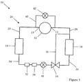
- FIG. 1 schematically shows a refrigeration system 10 having a refrigerant cycle or circuit 20 such that refrigerant can flow around the system.
- the system comprises a compressor 12 connected from an outlet or discharge 13 thereof via flow path 22 to a heat rejecting heat exchanger, which in this embodiment is-a condenser 14.
- the condenser 14 is connected via flow path 24 to expansion device 16, which is connected via flow path 26 to a heat accepting heat exchanger, which in this embodiment is an evaporator 18.
- the evaporator 18 is connected to the compressor 12 at an inlet or suction 11 thereof via flow path 28.
- the expansion device 16 is preferably a thermostatic expansion valve and in this embodiment is controlled in response to conditions of the system 10 via control line 36.
- the system condition which controls opening of the expansion valve 16 could for example be the temperature of the evaporator 18, or a related temperature such as a bulb temperature at the evaporator outlet, etc.
- additional optional components accumulator 32 and dryer 34 are also provided on flow path 24 between the condenser 14 and the valve 16.
- the system 10 further comprises a pressure equalisation valve (PEV) across the compressor 12, i.e. connecting the compressor suction 11 to the discharge 13.
- PEV pressure equalisation valve
- the PEV comprises a bypass passage 40 and means 42, such as a valve, far opening and closing the passage 40.
- the system 10 further comprises a liquid valve (LV), which in preferred embodiments is a liquid solenoid valve 44, in the flow path 24 between the condenser 14 and the expansion valve 16.
- LV liquid valve
- the LV 44 can be energised to open or close as required, thereby opening or closing the flow path 24 to enable or disable refrigerant flow around the circuit 20.
- high pressure and high temperature refrigerant vapour exits the compressor 12 and enters the condenser 14 where it is cooled to a lower temperature, high pressure liquid refrigerant.
- This liquid is then expanded to a lower pressure by the expansion valve 16 and passes to the evaporator 18 where the refrigerant boils and absorbs heat from its surroundings.
- the vapour at the evaporator 18 outlet is drawn into the compressor 12, completing the cycle.
- refrigerant may be present in the compressor 12 and, particularly if the compressor 12 is shut down for prolonged periods, additional refrigerant can migrate from the condenser 14 to the compressor 12 as discussed in more detail below.
- the refrigerant in the compressor 12 may condense on the compressor shell, particularly at low ambient temperatures, and the condensed refrigerant will mix with the compressor oil which has an affinity for refrigerant. If the compressor oil temperature is below the saturated discharge temperature of the refrigerant, the refrigerant can condense in the oil. The refrigerant dilutes the oil and, when the compressor 12 is restarted, the diluted oil is less effective at lubricating the components of the compressor 12, which may lead to damage. Furthermore the compressor oil pump will draw in refrigerant which may also lead to damage.
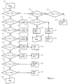
- FIG 2 is a flow diagram of one embodiment of the present invention in which a control means or the like determines the state of a system 10 (for example the system 10 of any of figures 1 , 6 , 7A or 8 ) and in particular the length of time T stop that the compressor has been shut down and the discharge temperature T ref of the compressor 12. If the compressor 12 is shut down for a reasonably long period of time, the discharge temperature T ref is substantially equal to the ambient temperature. In other embodiments the ambient temperature may be measured. The control means determines from these parameters what steps before and during compressor startup should be taken to minimise or eliminate the problems of refrigerant condensation in the compressor 12.
- a control means or the like determines the state of a system 10 (for example the system 10 of any of figures 1 , 6 , 7A or 8 ) and in particular the length of time T stop that the compressor has been shut down and the discharge temperature T ref of the compressor 12. If the compressor 12 is shut down for a reasonably long period of time, the discharge temperature T ref is substantially equal to the ambient temperature. In other embodiments the
- parameters could alternatively or additionally be used in this determination, such as the temperature of the oil in the compressor 12, the temperature of the refrigerant in the compressor 12, and/or the pressure inside the compressor shell, etc.
- the parameters used may depend on the sensors that are present in the system 10 and so what can be measured for making this determination.
- the sequence begins at step 1.1 and the time since the compressor 12 stopped T stop is determined in step 1.2. If it is less than 1 hour, the time is further determined in step 2.1 and still further in step 3.2 if T stop is less than 1/2 hour. For shutdown periods less than 1/2 hour, it is determined unnecessary to preheat the compressor 12 and a normal starting sequence (for example as shown in figure 3 ) begins in step 4.3. For shutdown periods between 1/2 and 1 hour, the discharge temperature, T ref is determined in step 3.1 and if it is low (less than 20°C), a short (3 minute) preheat of the compressor 12 is initiated in step 4.2 and as discussed below, before the normal starting sequence begins in step 5.2. However if T ref is sufficiently high already, no preheat is required and a short starting sequence (for example as shown in figure 5 ) begins in step 4.1.
- the discharge temperature T ref is determined in step 1.3 and dependent on the temperature, also in steps 1.4, 1.5. 1.6, 1.7 and 1.8. Furthermore, dependent on T ref , the compressor 12 is preheated for 12, 9, 6 or 3 minutes (steps 2.2, 2.3, 2.4 and 2.5 respectively) before a long starting sequence (for example as shown in figure 4 ) begins in step 3.3. However if T ref is sufficiently high (between 0 and 20°C) as determined in step 1.7, a 3 minute preheat is initiated in step 2.6 before the normal starting sequence begins in step 3.4.
- T ref is already even higher than 20°C as determined is steps 1.8 and 1.9, then no preheat is required and either a normal starting sequence is initiated in step 2.7 or for very high temperatures (greater than 40°C) a short starting sequence is initiated in step 2.8.
- the above sequences ensure that if the discharge temperature of the compressor 12 is low, the compressor 12 is heated, preferably prior to compressor startup, to raise the compressor temperature, including the oil temperature. This is advantageous not only because the viscosity of the oil is improved making the oil more suitable for lubricating the compressor components on startup, but also because a sufficiently high oil temperature (greater than the saturation discharge temperature of the refrigerant) reduces or eliminates refrigerant condensation in the compressor 12 that occurs when the compressor shell and oil are cool.
- Figures 3, 4 and 5 schematically illustrate preferred embodiments of the starting sequences for starting a compressor 12 after shutdown.
- Figure 3 shows a "normal" or default starting sequence
- figure 4 shows a long starting sequence
- figure 5 shows a short starting sequence.
- the starting sequences disclosed in figure 2 correspond with the figure 3, 4 sand 5 sequences, but it is also envisaged that this could differ or be modified by the skilled person.
- the preheat sequences disclosed in figures 3, 4 and 5 may correspond with the preheat sequences of figure 2 , or may differ or be modified.
- FIG 3 shows a normal starting sequence for a compressor 12.
- the discharge temperature of the compressor 12 is preferably at least 20°C or the compressor shutdown period was less than 1/2 hour.
- the pressure equalisation valve (PEV) 40, 42 is initially closed and so is the liquid valve (LV) 44.
- the PEV is opened thereby opening a bypass of the compressor 12.
- the compressor 12 is started, but with a relatively low frequency of about 30 Hz (which is significantly less than the full operating speed of the compressor 12).
- Heat from the bypassed refrigerant gas that passes through the PEV is transferred to the compressor 12 and to the compressor oil when the compressor 12 is started.
- the oil in the compressor 12 is (further) heated and the condensation risk is further minimised, particularly as the refrigerant bypassing the compressor 12 cannot condense in the compressor 12.
- the LV is closed to limit the flow of refrigerant into the compressor 12 thus further reducing the risk of condensation.
- the liquid valve is opened and the PEV remains open.
- the refrigerant flow at the compressor suction 11 increases slightly, but is still relatively low as the compressor 12 is still bypassed by the open PEV.
- the PEV when it is again measured, determined and/or expected to be greater than the saturated discharge temperature of the refrigerant, and/or in this embodiment after it has been heated for a sufficient period of time which in the normal starting sequence is a further 20 seconds, the PEV is closed whilst the liquid valve remains open. Refrigerant therefore flows around the circuit 20 of system 10 under the influence of the compressor 12, which is no longer bypassed.
- the speed of the compressor 12 is gradually increased, preferably by 5 Hz per second until an optimum or normal operating frequency is reached, after which standard compressor speed control is applied as is known in the art.
- the standard operating speed control can be started after it is again determined or otherwise expected that the oil temperature is still higher than the saturated discharge temperature.
- a normal starting sequence may not be appropriate under certain circumstances, for example when the temperature of the shutdown compressor 12 is low (e.g. less than about 5°C) and/or when the compressor 12 has been shutdown for a long period (more than about one hour).
- a long starting sequence as shown in figure 4 may be more appropriate.
- the long starting sequence differs from the normal starting sequence in that the periods between events are generally significantly longer. For example the LV is kept closed after compressor startup for 5 minutes rather than 20 seconds, thereby allowing the oil additional time to heat up. The delay before closing the PEV is also longer and is about 2 minutes thus allowing the system 10 to operate at a reduced flow rate for longer.
- the period of time before the compressor frequency is increased is also longer and is about 2 1/2 minutes after which the frequency is increased more slowly than the normal starting sequence, at about 1 Hz per 5 seconds.
- the long starting sequence differs at this stage from the normal starting sequence in that an additional step is included before standard compressor speed control is initiated, during which the compressor is operated at a maximum frequency of 60 Hz for 1 minute.
- the long starting sequence is significantly slower than the normal starting sequence thereby allowing the system temperature to increase gradually before fully loading the compressor 12, which is appropriate in colder conditions, particularly if the compressor 12 has been inactive for a long period of time. Furthermore it may be appropriate to heat the oil for a longer period prior to initiating the long starting sequence, as discussed in relation to figure 2 .
- a normal nor a long starting sequence may be appropriate, for example when the temperature of the shutdown compressor 12 is relatively high (e.g. more than about 40°C) and/or when the compressor 12 has been shutdown for only a brief period (less than an hour).
- a short starting sequence as shown in figure 5 may be more appropriate.
- the short starting sequence differs from the normal starting sequence in that the periods between events are generally much shorter and in some embodiments, little or no delay between events is needed.
- the LV is not kept closed after compressor startup but instead is opened up quickly as the oil perhaps does not need any additional time to heat up at the lower operating speed.
- the delay before closing the PEV is also short or may not even be required and the PEV can be closed quickly after compressor startup.
- the period of time before the compressor frequency is increased is also short and is about 5 seconds, after which the frequency is increased at a slower rate than the normal starting sequence, at about 1 Hz per second.
- the short starting sequence is significantly faster than the normal starting sequence as the system temperature does not need to increase gradually and the compressor 12 is capable of operating under full load relatively quickly. Furthermore it may not even be necessary to heat the oil prior to initiating the short starting sequence, as shown in figure 2 .
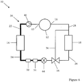
- Figure 6 schematically illustrates a refrigeration system which does not belong to the invention, although this system 10 could be and preferably is combined with the system 10 shown in figure 1 simply by adding the PEV of figure 1 (for example as shown in figure 8 ) or indeed with figure 7A .
- the components are mostly the same as those of the figure 1 embodiment and have like reference numerals.
- the figure 6 embodiment further comprises a check valve 46 which is a one-way valve that prevents flow or migration of fluid in one direction (from the condenser 14 towards the compressor 12) but permits flow of fluid in the other direction (towards the condenser 14 from the compressor 12).
- the system 10 of figure 6 operates as normal when the compressor 12 is running. However, in prior art systems when the compressor is shut down refrigerant migrates from the condenser and/or evaporator to the compressor due to the pressure and temperature differences, and the refrigerant can condense in the compressor and mix with the oil which is undesirable as discussed above. In the figure 6 embodiment however, refrigerant is effectively trapped between the check valve 46 and the liquid valve (LV) 44 and therefore does not reach the compressor 12. This embodiment operates as follows.
- the LV When the compressor 12 is stopped, the LV is closed (preferably the LV is a liquid solenoid valve and the valve is closed by energising the solenoid) and the check valve 46 is closed (preferably the check valve is also a solenoid valve and the valve is closed by energising the solenoid, or the check valve may be closed by the pressure differential between the condenser 14 and the compressor 12. Refrigerant, that would otherwise migrate to the compressor 12, is therefore retained in the refrigerant circuit 20 between the two valves 44, 46. Even if the pressure at the inlet and outlets of the check valve 46 are balanced, the check valve 46 will not open, because the check valve 46 in this embodiment comprises a spring inside (not shown) so that no leak occurs if the pressure is balanced.
- the inlet pressure of the check valve 46 must be above the outlet pressure to permit circulation of the fluid. Any additional components such as an accumulator 32 and a dryer 34 in the circuit 20 help to store the refrigerant during compressor shutdown.
- the LV is energised to be opened and the check valve 46 is energised or opens due to the changed pressure differential.
- Figure 7A illustrates a refrigeration system which does not belong to the invention
- the system 10 comprises similar components as the other embodiments, including the pressure equalisation valve 40, 42 discussed with regard to figure 1 and the figure 1 embodiment can be operated in accordance with the following disclosure as well.
- a conventional refrigeration system 110 is shown in figure 7B and is shown in a first state shortly after compressor shutdown and in a second state a longer time after shutdown.
- the oil 100 can migrate and begin to fill the evaporator 118 and also the relatively hot oil can fill the bulb of the expansion valve 116 control means 136 that is located at the exit of the evaporator 118 (i.e. in line 128).
- This can cause the expansion valve 116 to open even if that is not desired, further affecting the system performance on compressor startup and liquid in the compressor suction line can damage the compressor.
- the refrigeration system 10 of the embodiment of figure 7A overcomes this problem by provision of the PEV, which is opened during or preferably just after compressor shutdown. This equalises the pressure differential between the compressor suction 11 and discharge 13 and thus prevents migration of oil from the compressor to the low side of the system 10.
- Figure 8 schematically illustrates another embodiment of the present invention.
- the system 10 comprises a check valve 46, a liquid valve 44 and a pressure equalisation valve 40, 42. Therefore all of the advantages disclosed in relation to the other embodiments and discussed above are provided by this system having the combination of all the valves.
Landscapes
- Engineering & Computer Science (AREA)
- Physics & Mathematics (AREA)
- Mechanical Engineering (AREA)
- Thermal Sciences (AREA)
- General Engineering & Computer Science (AREA)
- Control Of Positive-Displacement Pumps (AREA)
- Air Conditioning Control Device (AREA)
- Compressor (AREA)
Description
- The present invention relates to methods and systems for compressor operation before and during compressor startup and/or shutdown and in particular to methods and systems for reliable startup of a compressor, even at low ambient temperatures.
- Conventional refrigeration or airconditioning systems typically comprise a compressor, a heat rejecting heat exchanger or condenser, an expansion valve or device and a heat accepting heat exchanger or evaporator. In operation, refrigerant is circulated through these components in a closed circuit. The pressure and temperature of the refrigerant vapour is increased by the compressor before entering the heat rejecting heat exchanger where it is cooled. The high pressure, lower temperature liquid is then expanded to a lower pressure by means of the expansion valve. In the heat accepting heat exchanger, the refrigerant boils and absorbs heat from its surroundings. The vapour at the heat accepting heat exchanger outlet is drawn into the compressor, completing the cycle.
- However on compressor shutdown and restart the components of the system, particularly the compressor, can be damaged or fail particularly in low ambient temperatures. Document
EP-A-1 702 667 discloses a refrigeration system according to the preamble ofclaim 1 and a method according to the preamble ofclaim 7. It is therefore an object of the present invention to provide a refrigeration system and a method of operating a refrigeration system, particularly although not exclusively for a transport refrigeration unit, the refrigeration system comprising a compressor and being operable such that failures of the system due to or on compressor start up are minimised, particularly when the compressor is started at low ambient temperatures. This is achieved with a refrigeration system according toclaim 1 and a method according toclaim 7. Preferably the refrigeration system is operable in at least one of a plurality of predetermined sequences, and the particular sequence (or sequences) used is preferably determined based on at least one parameter of the refrigeration system. Preferably the parameter (or parameters) comprises a system parameter measured by at least one sensor. - Heating of the component(s) of the compressor is carried out in any suitable manner. In a particularly preferred embodiment, the stator windings of a motor associated with the compressor, for example the internal electric alternating current motor (synchronous or asynchronous) of the compressor are electrically connected to an electrical source, e.g. a direct current source, to thereby heat the windings and thus heat the compressor.
- The pressure equalisation valve can be opened prior to compressor start up, but in preferred embodiments the pressure equalisation valve is opened when the compressor is started (preferably at substantially the same time as the compressor is started). For example in the embodiment where the pressure equalisation valve is a bypass passage, the passage is opened as the compressor is started to allow pressure balancing between the compressor suction and discharge by bypassing the compressor. Preferably the pressure equalisation valve is opened after the preheating steps discussed above.
- Preferably the compressor is started slowly, e.g. at a speed or frequency considerably lower than a standard operating frequency. Starting the compressor and opening the pressure equalisation valve allows oil in the compressor to be mixed. This is advantageous because in a shutdown compressor the temperature of the oil is not homogeneous in the compressor shell. When the compressor is started slowly with the pressure equalisation valve open (and therefore with very low refrigerant flow), the hot oil from the motor is mixed with the cold oil from the other parts and the oil is warmed. Furthermore the oil and other parts of the compressor are heated by the refrigerant that bypasses the compressor via the pressure equalisation valve, the vapour refrigerant from the discharge valve in the compressor being hotter than the actual suction gas refrigerant and when passing through the bypass and the compressor suction, the vapour heats the mechanical parts of the compressor and the oil. That is the bypass line generally emits heat to the compressor and heats the oil that is circulating in the compressor. Pressure in the compressor body or shell is limited by the bypass.
- In particularly preferred embodiments the oil temperature of the compressor is maintained above the saturated discharge temperature of the refrigerant in the compressor shell. At temperatures below the saturated discharge temperature the vapour refrigerant condenses and if the oil temperature is below the saturated discharge temperature, refrigerant will condense into the oil. Preferably the compressor shell temperature is also maintained above the saturated discharge temperature of the refrigerant. If the oil, and preferably also the mechanical components and the shell of the compressor, are above the saturated discharge temperature refrigerant will not condense in the compressor.
- Preferably the speed of the compressor at startup is lower than the normal running speed of the compressor as previously mentioned. For example in preferred embodiments the compressor at startup operates at a frequency of 30 Hz. Low compressor speed is desirable at startup because a low flow rate through the compressor minimises refrigerant condensation in the compressor.
- Preferably the liquid valve is closed prior to and during compressor startup. In particularly preferred embodiments the liquid valve closes as the compressor stops and remains closed during compressor shutdown. Closing the liquid valve on compressor shutdown limits the flow of refrigerant into the compressor limiting condensation in the compressor oil.
- Preferably at an appropriate time after compressor startup the liquid valve is opened. Therefore the system is operating in some states with both the pressure equalisation valve and the liquid valve open and the compressor operating at low frequency. This enables increased flow of refrigerant at the compressor suction, although the refrigerant flow is still lower than during normal system operation because the pressure equalisation valve is open (i.e. the compressor remains bypassed at this stage). Preferably the liquid valve is opened when it is determined that a system parameter is at a desired level. For example in a preferred embodiment the system parameter is the oil temperature and when the oil temperature is determined (for example by measurement with a temperature sensor) to be sufficiently high (for example above a predetermined limit, and/or above the saturated discharge temperature of the refrigerant in the compressor, etc.), then the liquid valve is opened. Other suitable parameters and limits could of course be used. For example in a preferred embodiment the parameter is alternatively or additionally the pressure in the compressor shell. Furthermore it is envisaged that the liquid valve could instead or additionally be opened in response to other events, for example after a predetermined period of time (e.g. from compressor startup, and/or from opening of the pressure equalisation valve, or from any other action or event, etc.).
- Preferably after the liquid valve is opened the pressure equalisation valve is closed. This occurs in response to any one or more of the following: after a predetermined period of time since opening the liquid valve; after a period of time has elapsed following any other suitable event; after a period of time has elapsed following one or more system parameters being determined to have reached a particular level; immediately after opening the liquid valve; etc. In a preferred embodiment the system parameter comprises either the compressor discharge temperature or the oil temperature and when the temperature is determined (for example by measurement with a temperature sensor) to be sufficiently high (for example above a predetermined limit, and/or above the saturated discharge temperature in the compressor, etc.), then the pressure equalisation valve is closed. The pressure of the suction and discharge of the compressor are therefore no longer balanced and refrigerant passes through the compressor at a greater flow rate than when the pressure equalisation valve was open (e.g. refrigerant no longer bypasses the compressor).
- The compressor speed is preferably then increased, either immediately or preferably in response to a measured system parameter reaching a predetermined limit and/or after a period of time has elapsed, etc. Preferably the compressor speed is slowly increased, preferably by a predetermined amount and/or at a predetermined rate, until a maximum or optimum speed is achieved and/or a predetermined time period has elapsed. Alternatively or additionally, when a measured system parameter is determined to have reached a predetermined level, the compressor speed may be set to the maximum (i.e. standard) operating speed (which is preferably after a period of slow increase in compressor speed from the initial startup speed). In a preferred embodiment, when the compressor discharge temperature and/or oil temperature of the compressor has reached a predetermined level, the compressor is controlled to operate at normal operating speeds.
- The above preferred systems and operational steps provide compressor starting sequences that enable a compressor to be started with minimal risk of failure which otherwise might occur due to condensation of refrigerant in the compressor, particularly at low ambient temperatures, after compressor shutdown. Refrigerant condensation is detrimental in a compressor because condensed refrigerant can become mixed with oil in the compressor sump, and if the oil temperature in the compressor is below the saturated discharge temperature of the refrigerant then refrigerant can condense in the oil. When the compressor is started refrigerant in the oil is pumped by the oil pump and may fail. Furthermore the oil viscosity is affected by the presence of refrigerant and therefore may be inappropriate for compressor operation causing damage to components that should be lubricated. These problems are solved by the preferred embodiments of the present invention and by the preferred methods discussed below. The present invention provides a method according to
claim 7. The starting speed of the compressor f1 is less than the compressor standard operating speed fs. Preferably f1 is about 30 Hz. Preferably fs is about 60 Hz, preferably about 65 Hz or greater. Preferably the method comprises the further steps of: further increasing the frequency of operation of the compressor to a standard operating frequency, preferably in response to a third event. - Preferably the first event comprises at least one of a first predetermined period of time elapsing and a measured compressor oil temperature being determinide to be above a predetermined threshold. Preferably the second event comprises at least one of a second predetermined period of time elapsing and a measured compressor oil temperature being determined to be above a predetermined threshold.
- Preferably the method further comprises the steps of providing at least one system sensor and measuring at least one parameter of the system with the sensor, and operating the system in at least one of a plurality of predetermined sequences based on the at least one parameter measured by the sensor.
- Preferably the step of preheating at least one component of the compressor comprises the steps of providing means for heating at least one component of the compressor, and activating the heating means to heat the component when it is determined that compressor startup is required. Preferably the means for heating at least one component of the compressor comprises means for heating at least one of the compressor body or shell, the oil in the compressor, and the compressor motor: In a particularly preferred embodiment the heating means comprises means for supplying DC electricity to the stator windings of an internal AC motor of the compressor. Preferably the method further comprises providing at least one sensor and measuring at least one parameter of the system with the sensor, and the heating means is activated for a predetermined period of time based on the at least one parameter. Preferably the predetermined period is based on at least one of the temperature of the oil in the compressor, the compressor shell temperature, the compressor discharge temperature, the ambient temperature and the length of time for which the compressor has been inactive.
- Preferably the method further comprises the steps of measuring the temperature of oil in the compressor, determining the saturated discharge temperature of refrigerant in the compressor, and heating at least one component of the compressor such that the oil is maintained at a temperature above the saturated discharge temperature.
- As discussed above, preheating a refrigeration system prior to compressor start up and controlling a liquid valve and a pressure equalisation valve before and during start up can advantageously reduce or eliminate refrigerant condensation problems, particularly in low ambient temperatures.
- The above-mentioned and other features of the various embodiments of the present invention will now be described, by way of example only and with reference to the accompanying drawings, in which:
-
Figure 1 shows a schematic representation a refrigeration system in accordance with an embodiment of the present invention; -
Figure 2 shows a flow diagram illustrating the modes of operation of a refrigeration system in accordance with an embodiment of the present invention; -
Figure 3 shows a first, standard operating sequence for starting a compressor of a refrigeration system in accordance with an embodiment of the present invention; -
Figure 4 shows a second, long operating sequence for starting a compressor of a refrigeration system in accordance with an embodiment of the present invention; - -
Figure 5 shows a third, short operating sequence for starting a compressor of a refrigeration system in accordance with an embodiment of the present invention; -
Figure 6 shows a schematic representation of a refrigeration system which does not belong to the invention; -
Figure 7A shows a schematic representation of a refrigeration system which does not belong to the invention; -
Figure 7B shows a system, that does not have the pressure equalisation valve of the embodiment offigure 7A , in two states, the first being shortly after compressor shutdown and the second being some time after compressor shutdown; and -
Figure 8 shows a schematic representation of a refrigeration system in accordance with another embodiment of the present invention. - The principles of the present invention can be incorporated within any suitable system. Examples of such suitable systems include refrigeration and airconditioning systems and particularly, although not exclusively, transport or truck refrigeration systems. For ease of reference, the specific embodiments discussed herein are described with reference to a refrigeration system suitable for a transport refrigeration unit or the like.
-
Figure 1 schematically shows arefrigeration system 10 having a refrigerant cycle orcircuit 20 such that refrigerant can flow around the system. The system comprises acompressor 12 connected from an outlet or discharge 13 thereof viaflow path 22 to a heat rejecting heat exchanger, which in this embodiment is-acondenser 14. Thecondenser 14 is connected viaflow path 24 toexpansion device 16, which is connected viaflow path 26 to a heat accepting heat exchanger, which in this embodiment is anevaporator 18. Theevaporator 18 is connected to thecompressor 12 at an inlet orsuction 11 thereof viaflow path 28. Theexpansion device 16 is preferably a thermostatic expansion valve and in this embodiment is controlled in response to conditions of thesystem 10 viacontrol line 36. The system condition which controls opening of theexpansion valve 16 could for example be the temperature of theevaporator 18, or a related temperature such as a bulb temperature at the evaporator outlet, etc. In this embodiment, additionaloptional components accumulator 32 anddryer 34 are also provided onflow path 24 between thecondenser 14 and thevalve 16. - The
system 10 further comprises a pressure equalisation valve (PEV) across thecompressor 12, i.e. connecting thecompressor suction 11 to thedischarge 13. The PEV comprises abypass passage 40 and means 42, such as a valve, far opening and closing thepassage 40. - The
system 10 further comprises a liquid valve (LV), which in preferred embodiments is aliquid solenoid valve 44, in theflow path 24 between thecondenser 14 and theexpansion valve 16. TheLV 44 can be energised to open or close as required, thereby opening or closing theflow path 24 to enable or disable refrigerant flow around thecircuit 20. - In operation, high pressure and high temperature refrigerant vapour exits the
compressor 12 and enters thecondenser 14 where it is cooled to a lower temperature, high pressure liquid refrigerant. This liquid is then expanded to a lower pressure by theexpansion valve 16 and passes to theevaporator 18 where the refrigerant boils and absorbs heat from its surroundings. The vapour at theevaporator 18 outlet is drawn into thecompressor 12, completing the cycle. - When the
compressor 12 is shut drown, refrigerant may be present in thecompressor 12 and, particularly if thecompressor 12 is shut down for prolonged periods, additional refrigerant can migrate from thecondenser 14 to thecompressor 12 as discussed in more detail below. - The refrigerant in the
compressor 12 may condense on the compressor shell, particularly at low ambient temperatures, and the condensed refrigerant will mix with the compressor oil which has an affinity for refrigerant. If the compressor oil temperature is below the saturated discharge temperature of the refrigerant, the refrigerant can condense in the oil. The refrigerant dilutes the oil and, when thecompressor 12 is restarted, the diluted oil is less effective at lubricating the components of thecompressor 12, which may lead to damage. Furthermore the compressor oil pump will draw in refrigerant which may also lead to damage. - Therefore in accordance with embodiments of the present invention, one or more compressor startup sequences are employed to minimise or eliminate refrigerant condensation in the
compressor 12.Figure 2 is a flow diagram of one embodiment of the present invention in which a control means or the like determines the state of a system 10 (for example thesystem 10 of any offigures 1 ,6 ,7A or8 ) and in particular the length of time Tstop that the compressor has been shut down and the discharge temperature Tref of thecompressor 12. If thecompressor 12 is shut down for a reasonably long period of time, the discharge temperature Tref is substantially equal to the ambient temperature. In other embodiments the ambient temperature may be measured. The control means determines from these parameters what steps before and during compressor startup should be taken to minimise or eliminate the problems of refrigerant condensation in thecompressor 12. Of course, other parameters could alternatively or additionally be used in this determination, such as the temperature of the oil in thecompressor 12, the temperature of the refrigerant in thecompressor 12, and/or the pressure inside the compressor shell, etc. The parameters used may depend on the sensors that are present in thesystem 10 and so what can be measured for making this determination. - In the
figure 2 embodiment, the sequence begins at step 1.1 and the time since thecompressor 12 stopped Tstop is determined in step 1.2. If it is less than 1 hour, the time is further determined in step 2.1 and still further in step 3.2 if Tstop is less than 1/2 hour. For shutdown periods less than 1/2 hour, it is determined unnecessary to preheat thecompressor 12 and a normal starting sequence (for example as shown infigure 3 ) begins in step 4.3. For shutdown periods between 1/2 and 1 hour, the discharge temperature, Tref is determined in step 3.1 and if it is low (less than 20°C), a short (3 minute) preheat of thecompressor 12 is initiated in step 4.2 and as discussed below, before the normal starting sequence begins in step 5.2. However if Tref is sufficiently high already, no preheat is required and a short starting sequence (for example as shown infigure 5 ) begins in step 4.1. - When the
compressor 12 has been shut down for longer than 1 hour, the discharge temperature Tref is determined in step 1.3 and dependent on the temperature, also in steps 1.4, 1.5. 1.6, 1.7 and 1.8. Furthermore, dependent on Tref, thecompressor 12 is preheated for 12, 9, 6 or 3 minutes (steps 2.2, 2.3, 2.4 and 2.5 respectively) before a long starting sequence (for example as shown infigure 4 ) begins in step 3.3. However if Tref is sufficiently high (between 0 and 20°C) as determined in step 1.7, a 3 minute preheat is initiated in step 2.6 before the normal starting sequence begins in step 3.4. If Tref is already even higher than 20°C as determined is steps 1.8 and 1.9, then no preheat is required and either a normal starting sequence is initiated in step 2.7 or for very high temperatures (greater than 40°C) a short starting sequence is initiated in step 2.8. - The above sequences ensure that if the discharge temperature of the
compressor 12 is low, thecompressor 12 is heated, preferably prior to compressor startup, to raise the compressor temperature, including the oil temperature. This is advantageous not only because the viscosity of the oil is improved making the oil more suitable for lubricating the compressor components on startup, but also because a sufficiently high oil temperature (greater than the saturation discharge temperature of the refrigerant) reduces or eliminates refrigerant condensation in thecompressor 12 that occurs when the compressor shell and oil are cool. -
Figures 3, 4 and 5 schematically illustrate preferred embodiments of the starting sequences for starting acompressor 12 after shutdown.Figure 3 shows a "normal" or default starting sequence,figure 4 shows a long starting sequence andfigure 5 shows a short starting sequence. In preferred embodiments the starting sequences disclosed infigure 2 correspond with thefigure 3, 4 sand 5 sequences, but it is also envisaged that this could differ or be modified by the skilled person. Furthermore the preheat sequences disclosed infigures 3, 4 and 5 may correspond with the preheat sequences offigure 2 , or may differ or be modified. -
Figure 3 shows a normal starting sequence for acompressor 12. In preferred embodiments, some or all of the steps of thefigure 2 sequence are carried out as the first step of the normal starting sequence. Therefore the discharge temperature of thecompressor 12 is preferably at least 20°C or the compressor shutdown period was less than 1/2 hour. Referring to asystem 10 as exemplified infigure 1 , the pressure equalisation valve (PEV) 40, 42 is initially closed and so is the liquid valve (LV) 44. When thecompressor 12 is to be started, the PEV is opened thereby opening a bypass of thecompressor 12. Thecompressor 12 is started, but with a relatively low frequency of about 30 Hz (which is significantly less than the full operating speed of the compressor 12). Heat from the bypassed refrigerant gas that passes through the PEV is transferred to thecompressor 12 and to the compressor oil when thecompressor 12 is started. Thus the oil in thecompressor 12 is (further) heated and the condensation risk is further minimised, particularly as the refrigerant bypassing thecompressor 12 cannot condense in thecompressor 12. Furthermore the LV is closed to limit the flow of refrigerant into thecompressor 12 thus further reducing the risk of condensation. - When the oil temperature in the
compressor 12 is sufficiently high, e.g. when it is measured, determined or otherwise expected to be greater than the saturated discharge temperature of the refrigerant, and/or in this embodiment after the oil has been heated for a sufficient period of time which in the normal starting sequence is 20 seconds, the liquid valve is opened and the PEV remains open. The refrigerant flow at thecompressor suction 11 increases slightly, but is still relatively low as thecompressor 12 is still bypassed by the open PEV. When the oil temperature in thecompressor 12 is sufficiently high, e.g. when it is again measured, determined and/or expected to be greater than the saturated discharge temperature of the refrigerant, and/or in this embodiment after it has been heated for a sufficient period of time which in the normal starting sequence is a further 20 seconds, the PEV is closed whilst the liquid valve remains open. Refrigerant therefore flows around thecircuit 20 ofsystem 10 under the influence of thecompressor 12, which is no longer bypassed. - When the oil temperature in the
compressor 12 is sufficiently high, e.g. when it is yet again measured, determined or otherwise expected to be greater than the saturated discharge temperature of the refrigerant, and/or in this embodiment after it has been heated for a sufficient period of time which in the normal starting sequence is a still further 20 seconds, the speed of thecompressor 12 is gradually increased, preferably by 5 Hz per second until an optimum or normal operating frequency is reached, after which standard compressor speed control is applied as is known in the art. In other embodiments, the standard operating speed control can be started after it is again determined or otherwise expected that the oil temperature is still higher than the saturated discharge temperature. - However a normal starting sequence may not be appropriate under certain circumstances, for example when the temperature of the
shutdown compressor 12 is low (e.g. less than about 5°C) and/or when thecompressor 12 has been shutdown for a long period (more than about one hour). Instead a long starting sequence as shown infigure 4 may be more appropriate. The long starting sequence differs from the normal starting sequence in that the periods between events are generally significantly longer. For example the LV is kept closed after compressor startup for 5 minutes rather than 20 seconds, thereby allowing the oil additional time to heat up. The delay before closing the PEV is also longer and is about 2 minutes thus allowing thesystem 10 to operate at a reduced flow rate for longer. The period of time before the compressor frequency is increased is also longer and is about 2 1/2 minutes after which the frequency is increased more slowly than the normal starting sequence, at about 1 Hz per 5 seconds. The long starting sequence differs at this stage from the normal starting sequence in that an additional step is included before standard compressor speed control is initiated, during which the compressor is operated at a maximum frequency of 60 Hz for 1 minute. The long starting sequence is significantly slower than the normal starting sequence thereby allowing the system temperature to increase gradually before fully loading thecompressor 12, which is appropriate in colder conditions, particularly if thecompressor 12 has been inactive for a long period of time. Furthermore it may be appropriate to heat the oil for a longer period prior to initiating the long starting sequence, as discussed in relation tofigure 2 . - However under other circumstances neither a normal nor a long starting sequence may be appropriate, for example when the temperature of the
shutdown compressor 12 is relatively high (e.g. more than about 40°C) and/or when thecompressor 12 has been shutdown for only a brief period (less than an hour). In such circumstances a short starting sequence as shown infigure 5 may be more appropriate. The short starting sequence differs from the normal starting sequence in that the periods between events are generally much shorter and in some embodiments, little or no delay between events is needed. For example the LV is not kept closed after compressor startup but instead is opened up quickly as the oil perhaps does not need any additional time to heat up at the lower operating speed. The delay before closing the PEV is also short or may not even be required and the PEV can be closed quickly after compressor startup. The period of time before the compressor frequency is increased is also short and is about 5 seconds, after which the frequency is increased at a slower rate than the normal starting sequence, at about 1 Hz per second. The short starting sequence is significantly faster than the normal starting sequence as the system temperature does not need to increase gradually and thecompressor 12 is capable of operating under full load relatively quickly. Furthermore it may not even be necessary to heat the oil prior to initiating the short starting sequence, as shown infigure 2 . -
Figure 6 schematically illustrates a refrigeration system which does not belong to the invention, although thissystem 10 could be and preferably is combined with thesystem 10 shown infigure 1 simply by adding the PEV offigure 1 (for example as shown infigure 8 ) or indeed withfigure 7A . In thefigure 6 embodiment, the components are mostly the same as those of thefigure 1 embodiment and have like reference numerals. However thefigure 6 embodiment further comprises acheck valve 46 which is a one-way valve that prevents flow or migration of fluid in one direction (from thecondenser 14 towards the compressor 12) but permits flow of fluid in the other direction (towards thecondenser 14 from the compressor 12). - The
system 10 offigure 6 operates as normal when thecompressor 12 is running. However, in prior art systems when the compressor is shut down refrigerant migrates from the condenser and/or evaporator to the compressor due to the pressure and temperature differences, and the refrigerant can condense in the compressor and mix with the oil which is undesirable as discussed above. In thefigure 6 embodiment however, refrigerant is effectively trapped between thecheck valve 46 and the liquid valve (LV) 44 and therefore does not reach thecompressor 12. This embodiment operates as follows. When thecompressor 12 is stopped, the LV is closed (preferably the LV is a liquid solenoid valve and the valve is closed by energising the solenoid) and thecheck valve 46 is closed (preferably the check valve is also a solenoid valve and the valve is closed by energising the solenoid, or the check valve may be closed by the pressure differential between thecondenser 14 and thecompressor 12. Refrigerant, that would otherwise migrate to thecompressor 12, is therefore retained in therefrigerant circuit 20 between the twovalves check valve 46 are balanced, thecheck valve 46 will not open, because thecheck valve 46 in this embodiment comprises a spring inside (not shown) so that no leak occurs if the pressure is balanced. The inlet pressure of thecheck valve 46 must be above the outlet pressure to permit circulation of the fluid. Any additional components such as anaccumulator 32 and adryer 34 in thecircuit 20 help to store the refrigerant during compressor shutdown. When thecompressor 12 is restarted, the LV is energised to be opened and thecheck valve 46 is energised or opens due to the changed pressure differential. -
Figure 7A illustrates a refrigeration system which does not belong to the invention Thesystem 10 comprises similar components as the other embodiments, including thepressure equalisation valve figure 1 and thefigure 1 embodiment can be operated in accordance with the following disclosure as well. - A
conventional refrigeration system 110 is shown infigure 7B and is shown in a first state shortly after compressor shutdown and in a second state a longer time after shutdown. When thecompressor 112 is shut down a large pressure differential exists between thecompressor suction 111 and thecompressor discharge 113, which effectively pushes thecompressor oil 100 out of thecompressor 112 on the suction side of thecircuit 120, intoline 128 and towards theevaporator 118. Therefore on compressor startup there is less oil than should be present, and in some cases little or no oil, in thecompressor 112 and the compressor components are likely to be damaged. Furthermore as shown in the second diagram offigure 7B , after a period of time theoil 100 can migrate and begin to fill theevaporator 118 and also the relatively hot oil can fill the bulb of theexpansion valve 116 control means 136 that is located at the exit of the evaporator 118 (i.e. in line 128). This can cause theexpansion valve 116 to open even if that is not desired, further affecting the system performance on compressor startup and liquid in the compressor suction line can damage the compressor. - The
refrigeration system 10 of the embodiment offigure 7A overcomes this problem by provision of the PEV, which is opened during or preferably just after compressor shutdown. This equalises the pressure differential between thecompressor suction 11 anddischarge 13 and thus prevents migration of oil from the compressor to the low side of thesystem 10. -
Figure 8 schematically illustrates another embodiment of the present invention. In this embodiment, thesystem 10 comprises acheck valve 46, aliquid valve 44 and apressure equalisation valve
Claims (14)
- A refrigeration system (10) comprising:a compressor (12) having a suction and a discharge;a heat rejecting heat exchanger (14);an expansion valve (16);a heat accepting heat exchanger (18);a pressure equalisation valve (40,42) for equalising the pressure differential between the compressor suction and compressor discharge, the pressure equalisation valve comprising a bypass passage (40) connecting the compressor suction to the compressor discharge to enable the compressor to be bypassed and a valve (42) to control flow of refrigerant therethrough; anda liquid valve (44), preferably a liquid solenoid valve, arranged in a flow line between the heat rejecting heat exchanger (14) and the expansion valve (16); characterised by further comprising:means for heating at least one component of the compressor (12);control means for activating the heating means when it is determined that compressor-startup is required, the control means starting the compressor after heating the at least one component; andat least one sensor, the sensor sensing at least one of the temperature of the oil in the compressor (12), the compressor shell temperature, the compressor discharge temperature, the ambient temperature and the length of time for which the compressor has been inactive;wherein the control means activates the heating means for a predetermined period of time based on at least one parameter of the system measured by the sensor, the predetermined period being based on at least one of the temperature of the oil in the compressor (12), the compressor shell temperature, the compressor discharge temperature, the ambient temperature and the length of time for which the compressor (12) has been inactive.
- A refrigeration system as claimed in claim 1, further comprising:control means for operating the system in at least one of a plurality of predetermined sequences; andat least one sensor, wherein the control means operates the system in a particular one of the plurality of predetermined sequences based on at least one parameter of the system measured by the sensor.
- A refrigeration system as claimed in claim 1 or 2, wherein the means for heating at least one component of the compressor (12) comprises means for heating at least one of the compressor body or shell, the oil in the compressor, and the compressor motor.
- A refrigeration system as claimed in any preceding claim, further comprising:a sensor for sensing the temperature of oil in the compressor (12);means for determining the saturated discharge temperature of refrigerant in the compressor (12); andcontrol means, wherein the means for heating at least one component of the compressor comprises means for heating at least the oil in the compressor, and wherein the control means controls the heating means such that the oil is maintained at a temperature above the saturated discharge temperature.
- A refrigeration system as claimed in any preceding claim, wherein the heating means comprises:means for providing an electrical current to windings of a motor of the compressor (12) to thereby heat the windings, and further comprising:control means for controlling heating of the windings, wherein the electrical current provided to the motor windings comprises direct current (DC) and is provided for at least one predetermined periods of time.
- A refrigeration system as claimed in any preceding claim, further comprising:control means, wherein the control means opens the pressure equalisation valve (40,42) at substantially the same time as starting the compressor (12).
- A method of optimizing startup of a compressor of a refrigeration system comprising the steps of:providing a refrigeration system comprising a compressor (12), a heat rejecting heat exchanger (14), an expansion valve (16), a heat accepting heat exchanger (18), and a pressure equalisation valve (40,42) that connects a suction and a discharge of the compressor (12) for equalising the- -pressure- differential between the compressor suction and compressor discharge;opening the pressure equalisation valve (40,42) to thereby reduce the pressure differential between the compressor suction and discharge; and starting the compressor (12), preferably at substantially the same time as opening the pressure equalisation valve; characterised bypreheating at least one component of the compressor (12) the step of preheating at least one component of the compressor (12) comprising the steps of:providing means for heating at least one component of the compressor (12); andactivating the heating means to heat the component when it is determined that compressor startup is required; and by
the step of starting the compressor (12) comprising operating the compressor (12) at a predetermined frequency f1 that is less than the operating frequency fn of the compressor (12) during normal operating conditions of the system, and by further comprising the step of:opening a liquid valve (44), provided in a refrigerant flow path between the heat rejecting heat exchanger (14) and the expansion valve (16), in response to a first event;closing the pressure equalisation valve (40,42) in response to a second event; andincreasing the operating frequency of the compressor (12). - A method as claimed in claim 7, further comprising the step of:further increasing the frequency of operation of the compressor (12) to the operating frequency fn of the compressor (12) during normal operating conditions of the system.
- A method as claimed in claims 7 or 8, wherein:the first event comprises at least one of a first predetermined period of time elapsing and a measured compressor oil temperature being determined to be above a predetermined threshold; andthe second event comprises at least one of a second predetermined period of time elapsing and a measured compressor oil temperature being determined to be above a predetermined threshold.
- A method as claimed in claim 7, 8 or 9, further comprising the steps of:providing at least one system sensor and measuring at least one parameter of the system with the sensor; andoperating the system in at least one of a plurality of predetermined sequences based on the at least one parameter measured by the sensor.
- A method as claimed in claims 7 to 10, wherein, the means for heating at least one component of the compressor comprises means for heating at least one of the compressor body or shell, the oil in the compressor (12) and the compressor motor.
- A method as claimed in claim 11, further comprising the step of:providing at least one sensor and measuring at least one parameter of the system with the sensor; and wherein the heating means is activated for a predetermined period of time based on the at least one parameter.
- A method as claimed in claim 12, wherein the predetermined period is based on at least one of the temperature of the oil in the compressor (12), the compressor shell temperature, the compressor discharge temperature, the ambient temperature and the length of time for which the compressor (12) has been inactive.
- A method as claimed in any of claims 7 to 13, further comprising the step of:measuring the temperature of oil in the compressor (12);determining the saturated discharge temperature of refrigerant in the compressor (12); andheating at least one component of the compressor such that the oil is maintained at a temperature above the saturated discharge temperature.
Applications Claiming Priority (1)
| Application Number | Priority Date | Filing Date | Title |
|---|---|---|---|
| PCT/IB2008/001908 WO2010010414A1 (en) | 2008-07-23 | 2008-07-23 | Methods and systems for compressor operation |
Publications (2)
| Publication Number | Publication Date |
|---|---|
| EP2321595A1 EP2321595A1 (en) | 2011-05-18 |
| EP2321595B1 true EP2321595B1 (en) | 2017-10-04 |
Family
ID=40242583
Family Applications (1)
| Application Number | Title | Priority Date | Filing Date |
|---|---|---|---|
| EP08788911.9A Active EP2321595B1 (en) | 2008-07-23 | 2008-07-23 | Methods and systems for compressor operation |
Country Status (4)
| Country | Link |
|---|---|
| US (1) | US20110113797A1 (en) |
| EP (1) | EP2321595B1 (en) |
| CN (1) | CN102105759B (en) |
| WO (1) | WO2010010414A1 (en) |
Cited By (1)
| Publication number | Priority date | Publication date | Assignee | Title |
|---|---|---|---|---|
| US11300339B2 (en) | 2018-04-05 | 2022-04-12 | Carrier Corporation | Method for optimizing pressure equalization in refrigeration equipment |
Families Citing this family (34)
| Publication number | Priority date | Publication date | Assignee | Title |
|---|---|---|---|---|
| EP2565323B1 (en) * | 2010-04-28 | 2018-12-19 | LG Electronics Inc. | Method for controlling the operation of a dryer |
| CN102859063A (en) * | 2010-04-28 | 2013-01-02 | Lg电子株式会社 | Control method of dryer |
| US20130047635A1 (en) * | 2011-08-31 | 2013-02-28 | Robert Bosch Gmbh | Starting method for a refrigerant recovery, recycling and recharging system |
| JP5240392B2 (en) * | 2011-09-30 | 2013-07-17 | ダイキン工業株式会社 | Refrigeration equipment |
| DE102012005878B4 (en) * | 2012-02-29 | 2022-08-04 | Liebherr-Hausgeräte Lienz Gmbh | refrigerator and/or freezer |
| US8931288B2 (en) * | 2012-10-19 | 2015-01-13 | Lennox Industries Inc. | Pressure regulation of an air conditioner |
| CN103776212B (en) * | 2012-10-25 | 2015-12-02 | 珠海格力电器股份有限公司 | Control method and control device for condensing unit in refrigeration system |
| CN105121981B (en) | 2013-04-12 | 2017-04-12 | 艾默生环境优化技术有限公司 | Compressor with wet start control |
| US10077929B2 (en) | 2013-05-08 | 2018-09-18 | Carrier Corporation | Movement of electronic expansion valve |
| CN103743059B (en) * | 2013-12-23 | 2016-08-17 | 广东美芝精密制造有限公司 | Air-conditioner and compressor thereof preheat control method, device |
| KR102198326B1 (en) * | 2013-12-26 | 2021-01-05 | 엘지전자 주식회사 | Air conditioner |
| CN104879881B (en) * | 2015-04-29 | 2017-06-27 | 广东美的制冷设备有限公司 | A kind of control method of air-conditioner with fixed frequency, controller and air-conditioner with fixed frequency |
| DK3332181T3 (en) | 2015-08-03 | 2021-10-25 | Carrier Corp | COOLING SYSTEM AND OPERATING PROCEDURE |
| CN105353796B (en) * | 2015-11-27 | 2017-12-22 | 珠海格力电器股份有限公司 | Refrigeration equipment and heating control circuit and heating control method of compressor of refrigeration equipment |
| CN105444448B (en) * | 2015-12-23 | 2018-02-06 | 广东美的暖通设备有限公司 | refrigeration system and its control method |
| CN105526683B (en) * | 2016-02-19 | 2018-09-07 | 珠海格力电器股份有限公司 | Control method and device of air conditioning system |
| CA3042117C (en) * | 2016-10-31 | 2021-02-16 | Hefei Hualing Co., Ltd. | Refrigeration apparatus |
| CN108072201B (en) | 2016-11-11 | 2022-02-01 | 开利公司 | Heat pump system and start control method thereof |
| CN107300272A (en) * | 2017-06-13 | 2017-10-27 | 珠海格力电器股份有限公司 | Condensing unit and air conditioner with same |
| JP6601472B2 (en) * | 2017-10-30 | 2019-11-06 | ダイキン工業株式会社 | Air conditioner |
| CN107763776A (en) * | 2017-11-20 | 2018-03-06 | 珠海格力电器股份有限公司 | Air Conditioning Unit and Refrigerant Migration Control Method |
| WO2019245675A1 (en) | 2018-06-22 | 2019-12-26 | Carrier Corporation | Oil control system and method for hvac system |
| KR102067602B1 (en) * | 2018-08-20 | 2020-01-17 | 엘지전자 주식회사 | Linear compressor and method for controlling linear compressor |
| CN110594979B (en) * | 2018-11-12 | 2024-01-23 | 杭州三花微通道换热器有限公司 | Air conditioning system control method |
| CN112594951A (en) * | 2020-12-14 | 2021-04-02 | 广东申菱环境系统股份有限公司 | Air conditioning unit refrigerating system and control method thereof |
| IT202100007316A1 (en) * | 2021-03-25 | 2022-09-25 | Ariston Spa | METHOD FOR MANAGING A HEAT PUMP OPERATING WITH AN OPERATING FLUID WITH LOW ENVIRONMENTAL IMPACT |
| EP4083535B1 (en) * | 2021-04-30 | 2023-12-27 | Trane International Inc. | Rapid restart chiller system |
| JP7539565B2 (en) * | 2021-05-06 | 2024-08-23 | 三菱電機株式会社 | Refrigeration cycle system and control method |
| CN113758035A (en) * | 2021-09-18 | 2021-12-07 | 广东美芝制冷设备有限公司 | Refrigerating system |
| CN114151992A (en) * | 2021-12-22 | 2022-03-08 | 珠海格力电器股份有限公司 | Compressor oil return control method and device and air conditioner |
| CN115523130A (en) * | 2022-09-23 | 2022-12-27 | 长虹华意压缩机股份有限公司 | Method for evaluating reliability of compressor |
| CN116985599A (en) * | 2023-07-18 | 2023-11-03 | 中通客车股份有限公司 | A control system and method for preventing air-conditioning and refrigeration failure |
| CN117329745B (en) * | 2023-11-21 | 2024-11-05 | 江苏拓米洛高端装备股份有限公司 | Refrigerating control device and method for environment test box |
| CN121594485A (en) * | 2024-08-15 | 2026-03-03 | 开利公司 | Control method and control device of air conditioning system and air conditioning system |
Citations (1)
| Publication number | Priority date | Publication date | Assignee | Title |
|---|---|---|---|---|
| US20040194485A1 (en) * | 2003-04-04 | 2004-10-07 | Dudley Kevin F. | Compressor protection from liquid hazards |
Family Cites Families (16)
| Publication number | Priority date | Publication date | Assignee | Title |
|---|---|---|---|---|
| US123839A (en) * | 1872-02-20 | Improvement in moustache-guards | ||
| US252223A (en) * | 1882-01-10 | Clover-huller | ||
| US201167A (en) * | 1878-03-12 | Improvement in automatic fire-alarms | ||
| US120112A (en) * | 1871-10-17 | Improvement in seed-droppers | ||
| US3398551A (en) * | 1966-10-03 | 1968-08-27 | Carrier Corp | Compressor control including pressure equalizer and overpressure means |
| DE3139460C1 (en) * | 1981-10-03 | 1983-06-01 | Danfoss A/S, 6430 Nordborg | Cold or heat pump installation |
| US5150581A (en) * | 1991-06-24 | 1992-09-29 | Baltimore Aircoil Company | Head pressure controller for air conditioning and refrigeration systems |
| JP3498009B2 (en) * | 1999-06-02 | 2004-02-16 | 三菱電機ビルテクノサービス株式会社 | Refrigeration equipment |
| US6550258B1 (en) * | 2000-11-22 | 2003-04-22 | Carrier Corporation | Pre-start bearing lubrication for refrigeration system compressor |
| US6490882B2 (en) * | 2001-03-27 | 2002-12-10 | Liebert Corporation | Method and apparatus for maintaining compressor discharge vapor volume for starting with condensing unit ambient temperatures less than evaporator unit ambient temperatures |
| US6993920B2 (en) * | 2004-01-30 | 2006-02-07 | Carrier Corporation | Heater cycling for improved oil return |
| DE602005020264D1 (en) * | 2004-03-01 | 2010-05-12 | Arcelik Anonim Sirketi Tuzla | COOLING DEVICE AND CONTROL PROCEDURE |
| KR101116208B1 (en) * | 2004-05-17 | 2012-03-06 | 삼성전자주식회사 | Control apparatus and method for compressor |
| KR100591321B1 (en) * | 2004-12-15 | 2006-06-19 | 엘지전자 주식회사 | Air conditioner |
| ITPN20050017A1 (en) * | 2005-03-14 | 2006-09-15 | Domnick Hunter Hiross S P A | "CONTROL SYSTEM FOR REFRIGERATED GAS COMPRESSED DRYERS". |
| JP4785207B2 (en) * | 2006-04-26 | 2011-10-05 | 東芝キヤリア株式会社 | Air conditioner |
-
2008
- 2008-07-23 EP EP08788911.9A patent/EP2321595B1/en active Active
- 2008-07-23 US US13/003,942 patent/US20110113797A1/en not_active Abandoned
- 2008-07-23 CN CN2008801304806A patent/CN102105759B/en active Active
- 2008-07-23 WO PCT/IB2008/001908 patent/WO2010010414A1/en not_active Ceased
Patent Citations (1)
| Publication number | Priority date | Publication date | Assignee | Title |
|---|---|---|---|---|
| US20040194485A1 (en) * | 2003-04-04 | 2004-10-07 | Dudley Kevin F. | Compressor protection from liquid hazards |
Cited By (1)
| Publication number | Priority date | Publication date | Assignee | Title |
|---|---|---|---|---|
| US11300339B2 (en) | 2018-04-05 | 2022-04-12 | Carrier Corporation | Method for optimizing pressure equalization in refrigeration equipment |
Also Published As
| Publication number | Publication date |
|---|---|
| HK1159234A1 (en) | 2012-07-27 |
| CN102105759A (en) | 2011-06-22 |
| EP2321595A1 (en) | 2011-05-18 |
| WO2010010414A1 (en) | 2010-01-28 |
| US20110113797A1 (en) | 2011-05-19 |
| CN102105759B (en) | 2013-11-13 |
Similar Documents
| Publication | Publication Date | Title |
|---|---|---|
| US20110113797A1 (en) | Methods and systems for compressor operation | |
| EP3575708B1 (en) | Refrigeration cycle device | |
| JP5095295B2 (en) | Water heater | |
| US9494352B2 (en) | Refrigerant system with control to address flooded compressor operation | |
| WO2009096620A1 (en) | A method and an apparatus for protecting a compressor of an air-conditioning system | |
| US3577741A (en) | Refrigeration apparatus | |
| CN107499492B (en) | Control method of water chilling unit | |
| JP4073340B2 (en) | Air conditioner and control method of air conditioner | |
| JPH10148405A (en) | Refrigeration / air conditioner | |
| EP2479516A2 (en) | Heat pump | |
| HK1159234B (en) | Methods and systems for compressor operation | |
| JP3977523B2 (en) | Air conditioner | |
| WO2022085125A1 (en) | Refrigeration cycle device | |
| JP5843642B2 (en) | Heat pump type liquid heating device | |
| JPH11142003A (en) | Refrigeration equipment | |
| JPH0821665A (en) | Method and apparatus for controlling discharge gas temperature of scroll compressor of refrigeration system | |
| JP4301546B2 (en) | Refrigeration equipment | |
| KR100287718B1 (en) | Control method for preheating of compressor in heat pump | |
| CN100406816C (en) | Method and device for preheating operation of frequency conversion driven compressor | |
| JP4326274B2 (en) | Refrigeration circuit | |
| JPH08313073A (en) | Refrigerating apparatus | |
| CN119451752A (en) | Centrifuge, centrifuge operation method and computer readable medium | |
| JPH1125344A (en) | Cooling device for automatic vending machine and control method for the same | |
| JP3684719B2 (en) | Heating and cooling machine | |
| JPH1062026A (en) | Air conditioner |
Legal Events
| Date | Code | Title | Description |
|---|---|---|---|
| PUAI | Public reference made under article 153(3) epc to a published international application that has entered the european phase |
Free format text: ORIGINAL CODE: 0009012 |
|
| 17P | Request for examination filed |
Effective date: 20110223 |
|
| AK | Designated contracting states |
Kind code of ref document: A1 Designated state(s): AT BE BG CH CY CZ DE DK EE ES FI FR GB GR HR HU IE IS IT LI LT LU LV MC MT NL NO PL PT RO SE SI SK TR |
|
| AX | Request for extension of the european patent |
Extension state: AL BA MK RS |
|
| DAX | Request for extension of the european patent (deleted) | ||
| 17Q | First examination report despatched |
Effective date: 20130305 |
|
| GRAP | Despatch of communication of intention to grant a patent |
Free format text: ORIGINAL CODE: EPIDOSNIGR1 |
|
| STAA | Information on the status of an ep patent application or granted ep patent |
Free format text: STATUS: GRANT OF PATENT IS INTENDED |
|
| INTG | Intention to grant announced |
Effective date: 20170424 |
|
| GRAA | (expected) grant |
Free format text: ORIGINAL CODE: 0009210 |
|
| GRAS | Grant fee paid |
Free format text: ORIGINAL CODE: EPIDOSNIGR3 |
|
| STAA | Information on the status of an ep patent application or granted ep patent |
Free format text: STATUS: THE PATENT HAS BEEN GRANTED |
|
| AK | Designated contracting states |
Kind code of ref document: B1 Designated state(s): AT BE BG CH CY CZ DE DK EE ES FI FR GB GR HR HU IE IS IT LI LT LU LV MC MT NL NO PL PT RO SE SI SK TR |
|
| REG | Reference to a national code |
Ref country code: GB Ref legal event code: FG4D |
|
| REG | Reference to a national code |
Ref country code: CH Ref legal event code: EP |
|
| REG | Reference to a national code |
Ref country code: AT Ref legal event code: REF Ref document number: 934439 Country of ref document: AT Kind code of ref document: T Effective date: 20171015 |
|
| REG | Reference to a national code |
Ref country code: IE Ref legal event code: FG4D |
|
| REG | Reference to a national code |
Ref country code: DE Ref legal event code: R096 Ref document number: 602008052384 Country of ref document: DE |
|
| REG | Reference to a national code |
Ref country code: NL Ref legal event code: MP Effective date: 20171004 |
|
| REG | Reference to a national code |
Ref country code: LT Ref legal event code: MG4D |
|
| REG | Reference to a national code |
Ref country code: AT Ref legal event code: MK05 Ref document number: 934439 Country of ref document: AT Kind code of ref document: T Effective date: 20171004 |
|
| PG25 | Lapsed in a contracting state [announced via postgrant information from national office to epo] |
Ref country code: NL Free format text: LAPSE BECAUSE OF FAILURE TO SUBMIT A TRANSLATION OF THE DESCRIPTION OR TO PAY THE FEE WITHIN THE PRESCRIBED TIME-LIMIT Effective date: 20171004 |
|
| PG25 | Lapsed in a contracting state [announced via postgrant information from national office to epo] |
Ref country code: NO Free format text: LAPSE BECAUSE OF FAILURE TO SUBMIT A TRANSLATION OF THE DESCRIPTION OR TO PAY THE FEE WITHIN THE PRESCRIBED TIME-LIMIT Effective date: 20180104 Ref country code: SE Free format text: LAPSE BECAUSE OF FAILURE TO SUBMIT A TRANSLATION OF THE DESCRIPTION OR TO PAY THE FEE WITHIN THE PRESCRIBED TIME-LIMIT Effective date: 20171004 Ref country code: LT Free format text: LAPSE BECAUSE OF FAILURE TO SUBMIT A TRANSLATION OF THE DESCRIPTION OR TO PAY THE FEE WITHIN THE PRESCRIBED TIME-LIMIT Effective date: 20171004 Ref country code: ES Free format text: LAPSE BECAUSE OF FAILURE TO SUBMIT A TRANSLATION OF THE DESCRIPTION OR TO PAY THE FEE WITHIN THE PRESCRIBED TIME-LIMIT Effective date: 20171004 Ref country code: FI Free format text: LAPSE BECAUSE OF FAILURE TO SUBMIT A TRANSLATION OF THE DESCRIPTION OR TO PAY THE FEE WITHIN THE PRESCRIBED TIME-LIMIT Effective date: 20171004 |
|
| PG25 | Lapsed in a contracting state [announced via postgrant information from national office to epo] |
Ref country code: LV Free format text: LAPSE BECAUSE OF FAILURE TO SUBMIT A TRANSLATION OF THE DESCRIPTION OR TO PAY THE FEE WITHIN THE PRESCRIBED TIME-LIMIT Effective date: 20171004 Ref country code: IS Free format text: LAPSE BECAUSE OF FAILURE TO SUBMIT A TRANSLATION OF THE DESCRIPTION OR TO PAY THE FEE WITHIN THE PRESCRIBED TIME-LIMIT Effective date: 20180204 Ref country code: GR Free format text: LAPSE BECAUSE OF FAILURE TO SUBMIT A TRANSLATION OF THE DESCRIPTION OR TO PAY THE FEE WITHIN THE PRESCRIBED TIME-LIMIT Effective date: 20180105 Ref country code: HR Free format text: LAPSE BECAUSE OF FAILURE TO SUBMIT A TRANSLATION OF THE DESCRIPTION OR TO PAY THE FEE WITHIN THE PRESCRIBED TIME-LIMIT Effective date: 20171004 Ref country code: AT Free format text: LAPSE BECAUSE OF FAILURE TO SUBMIT A TRANSLATION OF THE DESCRIPTION OR TO PAY THE FEE WITHIN THE PRESCRIBED TIME-LIMIT Effective date: 20171004 Ref country code: BG Free format text: LAPSE BECAUSE OF FAILURE TO SUBMIT A TRANSLATION OF THE DESCRIPTION OR TO PAY THE FEE WITHIN THE PRESCRIBED TIME-LIMIT Effective date: 20180104 |
|
| REG | Reference to a national code |
Ref country code: FR Ref legal event code: PLFP Year of fee payment: 11 |
|
| REG | Reference to a national code |
Ref country code: DE Ref legal event code: R097 Ref document number: 602008052384 Country of ref document: DE |
|
| PG25 | Lapsed in a contracting state [announced via postgrant information from national office to epo] |
Ref country code: CZ Free format text: LAPSE BECAUSE OF FAILURE TO SUBMIT A TRANSLATION OF THE DESCRIPTION OR TO PAY THE FEE WITHIN THE PRESCRIBED TIME-LIMIT Effective date: 20171004 Ref country code: SK Free format text: LAPSE BECAUSE OF FAILURE TO SUBMIT A TRANSLATION OF THE DESCRIPTION OR TO PAY THE FEE WITHIN THE PRESCRIBED TIME-LIMIT Effective date: 20171004 Ref country code: EE Free format text: LAPSE BECAUSE OF FAILURE TO SUBMIT A TRANSLATION OF THE DESCRIPTION OR TO PAY THE FEE WITHIN THE PRESCRIBED TIME-LIMIT Effective date: 20171004 Ref country code: DK Free format text: LAPSE BECAUSE OF FAILURE TO SUBMIT A TRANSLATION OF THE DESCRIPTION OR TO PAY THE FEE WITHIN THE PRESCRIBED TIME-LIMIT Effective date: 20171004 |
|
| PLBE | No opposition filed within time limit |
Free format text: ORIGINAL CODE: 0009261 |
|
| STAA | Information on the status of an ep patent application or granted ep patent |
Free format text: STATUS: NO OPPOSITION FILED WITHIN TIME LIMIT |
|
| PG25 | Lapsed in a contracting state [announced via postgrant information from national office to epo] |
Ref country code: RO Free format text: LAPSE BECAUSE OF FAILURE TO SUBMIT A TRANSLATION OF THE DESCRIPTION OR TO PAY THE FEE WITHIN THE PRESCRIBED TIME-LIMIT Effective date: 20171004 Ref country code: IT Free format text: LAPSE BECAUSE OF FAILURE TO SUBMIT A TRANSLATION OF THE DESCRIPTION OR TO PAY THE FEE WITHIN THE PRESCRIBED TIME-LIMIT Effective date: 20171004 Ref country code: PL Free format text: LAPSE BECAUSE OF FAILURE TO SUBMIT A TRANSLATION OF THE DESCRIPTION OR TO PAY THE FEE WITHIN THE PRESCRIBED TIME-LIMIT Effective date: 20171004 |
|
| 26N | No opposition filed |
Effective date: 20180705 |
|
| PG25 | Lapsed in a contracting state [announced via postgrant information from national office to epo] |
Ref country code: SI Free format text: LAPSE BECAUSE OF FAILURE TO SUBMIT A TRANSLATION OF THE DESCRIPTION OR TO PAY THE FEE WITHIN THE PRESCRIBED TIME-LIMIT Effective date: 20171004 |
|
| REG | Reference to a national code |
Ref country code: CH Ref legal event code: PL |
|
| PG25 | Lapsed in a contracting state [announced via postgrant information from national office to epo] |
Ref country code: MC Free format text: LAPSE BECAUSE OF FAILURE TO SUBMIT A TRANSLATION OF THE DESCRIPTION OR TO PAY THE FEE WITHIN THE PRESCRIBED TIME-LIMIT Effective date: 20171004 Ref country code: LU Free format text: LAPSE BECAUSE OF NON-PAYMENT OF DUE FEES Effective date: 20180723 |
|
| REG | Reference to a national code |
Ref country code: BE Ref legal event code: MM Effective date: 20180731 |
|
| REG | Reference to a national code |
Ref country code: IE Ref legal event code: MM4A |
|
| PG25 | Lapsed in a contracting state [announced via postgrant information from national office to epo] |
Ref country code: IE Free format text: LAPSE BECAUSE OF NON-PAYMENT OF DUE FEES Effective date: 20180723 Ref country code: CH Free format text: LAPSE BECAUSE OF NON-PAYMENT OF DUE FEES Effective date: 20180731 Ref country code: LI Free format text: LAPSE BECAUSE OF NON-PAYMENT OF DUE FEES Effective date: 20180731 |
|
| PG25 | Lapsed in a contracting state [announced via postgrant information from national office to epo] |
Ref country code: BE Free format text: LAPSE BECAUSE OF NON-PAYMENT OF DUE FEES Effective date: 20180731 |
|
| PG25 | Lapsed in a contracting state [announced via postgrant information from national office to epo] |
Ref country code: MT Free format text: LAPSE BECAUSE OF NON-PAYMENT OF DUE FEES Effective date: 20180723 |
|
| PG25 | Lapsed in a contracting state [announced via postgrant information from national office to epo] |
Ref country code: TR Free format text: LAPSE BECAUSE OF FAILURE TO SUBMIT A TRANSLATION OF THE DESCRIPTION OR TO PAY THE FEE WITHIN THE PRESCRIBED TIME-LIMIT Effective date: 20171004 |
|
| PG25 | Lapsed in a contracting state [announced via postgrant information from national office to epo] |
Ref country code: PT Free format text: LAPSE BECAUSE OF FAILURE TO SUBMIT A TRANSLATION OF THE DESCRIPTION OR TO PAY THE FEE WITHIN THE PRESCRIBED TIME-LIMIT Effective date: 20171004 Ref country code: HU Free format text: LAPSE BECAUSE OF FAILURE TO SUBMIT A TRANSLATION OF THE DESCRIPTION OR TO PAY THE FEE WITHIN THE PRESCRIBED TIME-LIMIT; INVALID AB INITIO Effective date: 20080723 |
|
| PG25 | Lapsed in a contracting state [announced via postgrant information from national office to epo] |
Ref country code: CY Free format text: LAPSE BECAUSE OF FAILURE TO SUBMIT A TRANSLATION OF THE DESCRIPTION OR TO PAY THE FEE WITHIN THE PRESCRIBED TIME-LIMIT Effective date: 20171004 |
|
| PGFP | Annual fee paid to national office [announced via postgrant information from national office to epo] |
Ref country code: GB Payment date: 20250619 Year of fee payment: 18 |
|
| PGFP | Annual fee paid to national office [announced via postgrant information from national office to epo] |
Ref country code: FR Payment date: 20250620 Year of fee payment: 18 |
|
| PGFP | Annual fee paid to national office [announced via postgrant information from national office to epo] |
Ref country code: DE Payment date: 20250620 Year of fee payment: 18 |