EP2320491B1 - Battery pack - Google Patents
Battery pack Download PDFInfo
- Publication number
- EP2320491B1 EP2320491B1 EP10176881.0A EP10176881A EP2320491B1 EP 2320491 B1 EP2320491 B1 EP 2320491B1 EP 10176881 A EP10176881 A EP 10176881A EP 2320491 B1 EP2320491 B1 EP 2320491B1
- Authority
- EP
- European Patent Office
- Prior art keywords
- battery pack
- bare cell
- protection circuit
- hole
- protrusion
- Prior art date
- Legal status (The legal status is an assumption and is not a legal conclusion. Google has not performed a legal analysis and makes no representation as to the accuracy of the status listed.)
- Active
Links
- 230000001681 protective effect Effects 0.000 claims description 37
- 238000003466 welding Methods 0.000 claims description 15
- 238000004519 manufacturing process Methods 0.000 claims description 2
- 238000009413 insulation Methods 0.000 description 10
- 238000007599 discharging Methods 0.000 description 9
- 238000006073 displacement reaction Methods 0.000 description 6
- 125000006850 spacer group Chemical group 0.000 description 6
- PXHVJJICTQNCMI-UHFFFAOYSA-N Nickel Chemical compound [Ni] PXHVJJICTQNCMI-UHFFFAOYSA-N 0.000 description 3
- 239000000853 adhesive Substances 0.000 description 3
- 230000001276 controlling effect Effects 0.000 description 3
- 230000007547 defect Effects 0.000 description 3
- 230000001105 regulatory effect Effects 0.000 description 3
- 230000001070 adhesive effect Effects 0.000 description 2
- 239000003792 electrolyte Substances 0.000 description 2
- 238000000034 method Methods 0.000 description 2
- HBBGRARXTFLTSG-UHFFFAOYSA-N Lithium ion Chemical compound [Li+] HBBGRARXTFLTSG-UHFFFAOYSA-N 0.000 description 1
- 230000002159 abnormal effect Effects 0.000 description 1
- 230000004308 accommodation Effects 0.000 description 1
- XAGFODPZIPBFFR-UHFFFAOYSA-N aluminium Chemical compound [Al] XAGFODPZIPBFFR-UHFFFAOYSA-N 0.000 description 1
- 229910052782 aluminium Inorganic materials 0.000 description 1
- 230000001413 cellular effect Effects 0.000 description 1
- 230000008878 coupling Effects 0.000 description 1
- 238000010168 coupling process Methods 0.000 description 1
- 238000005859 coupling reaction Methods 0.000 description 1
- 238000005516 engineering process Methods 0.000 description 1
- 239000002803 fossil fuel Substances 0.000 description 1
- 229910001416 lithium ion Inorganic materials 0.000 description 1
- 239000000463 material Substances 0.000 description 1
- 229910052759 nickel Inorganic materials 0.000 description 1
- 230000035515 penetration Effects 0.000 description 1
- 238000007789 sealing Methods 0.000 description 1
- 239000010409 thin film Substances 0.000 description 1
Images


Classifications
-
- H—ELECTRICITY
- H01—ELECTRIC ELEMENTS
- H01M—PROCESSES OR MEANS, e.g. BATTERIES, FOR THE DIRECT CONVERSION OF CHEMICAL ENERGY INTO ELECTRICAL ENERGY
- H01M50/00—Constructional details or processes of manufacture of the non-active parts of electrochemical cells other than fuel cells, e.g. hybrid cells
- H01M50/50—Current conducting connections for cells or batteries
- H01M50/572—Means for preventing undesired use or discharge
-
- H—ELECTRICITY
- H01—ELECTRIC ELEMENTS
- H01M—PROCESSES OR MEANS, e.g. BATTERIES, FOR THE DIRECT CONVERSION OF CHEMICAL ENERGY INTO ELECTRICAL ENERGY
- H01M10/00—Secondary cells; Manufacture thereof
- H01M10/42—Methods or arrangements for servicing or maintenance of secondary cells or secondary half-cells
- H01M10/425—Structural combination with electronic components, e.g. electronic circuits integrated to the outside of the casing
-
- H—ELECTRICITY
- H01—ELECTRIC ELEMENTS
- H01M—PROCESSES OR MEANS, e.g. BATTERIES, FOR THE DIRECT CONVERSION OF CHEMICAL ENERGY INTO ELECTRICAL ENERGY
- H01M10/00—Secondary cells; Manufacture thereof
- H01M10/05—Accumulators with non-aqueous electrolyte
- H01M10/052—Li-accumulators
- H01M10/0525—Rocking-chair batteries, i.e. batteries with lithium insertion or intercalation in both electrodes; Lithium-ion batteries
-
- H—ELECTRICITY
- H01—ELECTRIC ELEMENTS
- H01M—PROCESSES OR MEANS, e.g. BATTERIES, FOR THE DIRECT CONVERSION OF CHEMICAL ENERGY INTO ELECTRICAL ENERGY
- H01M50/00—Constructional details or processes of manufacture of the non-active parts of electrochemical cells other than fuel cells, e.g. hybrid cells
- H01M50/10—Primary casings, jackets or wrappings of a single cell or a single battery
- H01M50/147—Lids or covers
-
- H—ELECTRICITY
- H01—ELECTRIC ELEMENTS
- H01M—PROCESSES OR MEANS, e.g. BATTERIES, FOR THE DIRECT CONVERSION OF CHEMICAL ENERGY INTO ELECTRICAL ENERGY
- H01M50/00—Constructional details or processes of manufacture of the non-active parts of electrochemical cells other than fuel cells, e.g. hybrid cells
- H01M50/20—Mountings; Secondary casings or frames; Racks, modules or packs; Suspension devices; Shock absorbers; Transport or carrying devices; Holders
- H01M50/202—Casings or frames around the primary casing of a single cell or a single battery
-
- H—ELECTRICITY
- H01—ELECTRIC ELEMENTS
- H01M—PROCESSES OR MEANS, e.g. BATTERIES, FOR THE DIRECT CONVERSION OF CHEMICAL ENERGY INTO ELECTRICAL ENERGY
- H01M50/00—Constructional details or processes of manufacture of the non-active parts of electrochemical cells other than fuel cells, e.g. hybrid cells
- H01M50/20—Mountings; Secondary casings or frames; Racks, modules or packs; Suspension devices; Shock absorbers; Transport or carrying devices; Holders
- H01M50/271—Lids or covers for the racks or secondary casings
-
- H—ELECTRICITY
- H01—ELECTRIC ELEMENTS
- H01M—PROCESSES OR MEANS, e.g. BATTERIES, FOR THE DIRECT CONVERSION OF CHEMICAL ENERGY INTO ELECTRICAL ENERGY
- H01M50/00—Constructional details or processes of manufacture of the non-active parts of electrochemical cells other than fuel cells, e.g. hybrid cells
- H01M50/50—Current conducting connections for cells or batteries
- H01M50/572—Means for preventing undesired use or discharge
- H01M50/584—Means for preventing undesired use or discharge for preventing incorrect connections inside or outside the batteries
- H01M50/588—Means for preventing undesired use or discharge for preventing incorrect connections inside or outside the batteries outside the batteries, e.g. incorrect connections of terminals or busbars
-
- H—ELECTRICITY
- H01—ELECTRIC ELEMENTS
- H01M—PROCESSES OR MEANS, e.g. BATTERIES, FOR THE DIRECT CONVERSION OF CHEMICAL ENERGY INTO ELECTRICAL ENERGY
- H01M50/00—Constructional details or processes of manufacture of the non-active parts of electrochemical cells other than fuel cells, e.g. hybrid cells
- H01M50/50—Current conducting connections for cells or batteries
- H01M50/572—Means for preventing undesired use or discharge
- H01M50/584—Means for preventing undesired use or discharge for preventing incorrect connections inside or outside the batteries
- H01M50/59—Means for preventing undesired use or discharge for preventing incorrect connections inside or outside the batteries characterised by the protection means
- H01M50/593—Spacers; Insulating plates
-
- H—ELECTRICITY
- H01—ELECTRIC ELEMENTS
- H01M—PROCESSES OR MEANS, e.g. BATTERIES, FOR THE DIRECT CONVERSION OF CHEMICAL ENERGY INTO ELECTRICAL ENERGY
- H01M50/00—Constructional details or processes of manufacture of the non-active parts of electrochemical cells other than fuel cells, e.g. hybrid cells
- H01M50/50—Current conducting connections for cells or batteries
- H01M50/572—Means for preventing undesired use or discharge
- H01M50/584—Means for preventing undesired use or discharge for preventing incorrect connections inside or outside the batteries
- H01M50/59—Means for preventing undesired use or discharge for preventing incorrect connections inside or outside the batteries characterised by the protection means
- H01M50/595—Tapes
-
- Y—GENERAL TAGGING OF NEW TECHNOLOGICAL DEVELOPMENTS; GENERAL TAGGING OF CROSS-SECTIONAL TECHNOLOGIES SPANNING OVER SEVERAL SECTIONS OF THE IPC; TECHNICAL SUBJECTS COVERED BY FORMER USPC CROSS-REFERENCE ART COLLECTIONS [XRACs] AND DIGESTS
- Y02—TECHNOLOGIES OR APPLICATIONS FOR MITIGATION OR ADAPTATION AGAINST CLIMATE CHANGE
- Y02E—REDUCTION OF GREENHOUSE GAS [GHG] EMISSIONS, RELATED TO ENERGY GENERATION, TRANSMISSION OR DISTRIBUTION
- Y02E60/00—Enabling technologies; Technologies with a potential or indirect contribution to GHG emissions mitigation
- Y02E60/10—Energy storage using batteries
Definitions
- the present invention relates to a battery pack.
- such secondary batteries are used in the form of a battery pack integrated with a circuit for controlling charging and discharging operations.
- the battery pack has a circuit for efficiently controlling abnormal operating environments such as overcharging, overdischarging, overcurrent, or the like.
- the circuit mounted on a battery is covered by an upper cover.
- Conventional battery packs do not include an assembly structure for aligning the upper cover at the correct position on the battery and assembling the upper cover to the battery, and thus loss time increases during the assembly of the upper cover and defects caused by misalignment increase.
- the present invention aims to provide a battery pack having an improved upper cover assembly structure.
- a battery pack comprising a bare cell including a cap assembly having a terminal, a protection circuit module mounted to the bare cell, the protection circuit module comprising a protection circuit board and a protective device, the protection circuit board having a through hole arranged to permit welding of the protective device to the terminal through the through hole and a cover for covering the protection circuit module, the cover comprising a protrusion arranged to engage with the through hole to retain the cover to the protection circuit board.
- the protrusion may comprise a rib structure comprising first and second ribs arranged in a cross shape, wherein ends of the ribs are arranged to engage with sides of the through hole.
- the protrusion may have substantially the same shape as the through hole, the sides of the protrusion being arranged to engage with sides of the through hole.
- the protrusion may have a rectangular cross-section.
- the protrusion may have rounded portions at edges thereof to assist in locating the protrusion into the through hole.
- the protection circuit board may comprise first and second electrode pads.
- One end of the protective device may be connected to the first electrode pad via a first connecting member, the other end of the protective device being welded to the terminal of the cap assembly.
- the second electrode pad may be connected to an upper surface of the cap assembly via a second connecting member.
- the cap assembly may include a recess shaped to receive an end of the second connecting member so as to align the protection circuit board with the bare cell.
- the first connecting member may be a flat plate and the second connecting member may have a stepped shape for supporting the protection circuit board on the cap assembly.
- the battery pack may further comprise double-sided tape disposed between the protection circuit board and the cover to fix the cover to the protection circuit board.
- the cover may further comprise a skirt disposed along one or more edges of the cover for engaging with a side portion of the bare cell.
- the battery pack may further comprise an insulating sleeve arranged to surround the bare cell.
- the battery pack may further comprise an insulating element disposed between the cap assembly and the protective device, the insulating element having an opening corresponding to a safety vent in the bare cell.
- a method of making the battery pack may include mounting the protection circuit module to the bare cell, welding the protective device to the terminal of the bare cell through the through hole in the protection circuit board, and pushing the cover onto the bare cell such that the protrusion engages with the through hole to align the cover to the bare cell.
- an assembly position of an upper cover is efficiently determined by improving the assembly structure of the upper cover to protect the circuit, and thus assembling workability may be improved.
- loss time caused by displacement of the upper cover may be reduced since the upper cover is fixed at the right position, and defects caused by misalignment may also be reduced.
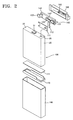
- the battery pack includes a bare cell 100 including an element generating electric power, a protective circuit module (PCM) 150 mounted on the bare cell 100 and controlling a charging and discharging operation, and an upper cover 160 connected to the bare cell 100 so as to accommodate the PCM 150.
- PCM protective circuit module
- the bare cell 100 is a rechargeable secondary battery, e.g., a lithium-ion battery, in which an electrode assembly 10 including a cathode plate 11, an anode plate 13, and a separator 15 is impregnated in an electrolyte (not shown) and sealed in a can 20.
- the bare cell 100 includes an electrode assembly 10 including a stack of a cathode plate 11, an anode plate 13, and a separator 15 and jelly-roll wound, a can 20 having an opening at the upper end to accommodate the electrode assembly 10 and the electrolyte, and a cap assembly 30 sealing the opening of the upper end of the can 20.
- the upper end of the can 20 is closed by the cap assembly 30 after the electrode assembly 10 is accommodated therein.
- the cap assembly 30 and the can 20 may be airtight-coupled by welding the contact portion thereof using a laser beam.
- the anode tap 17 of the electrode assembly 10 is connected to the cap assembly 30 itself, and the cathode tap 19 is connected to a first terminal 31 extending from the upper surface of the cap assembly 30.
- the first terminal 31 is bound to the cap assembly 30 while insulated from the cap assembly 30 and extends from the upper surface of the cap assembly 30 to electrically connect the bare cell 100 and the PCM 150.
- a safety vent 35 that is designed to break so as to provide a path of a gas when an internal pressure of the can 20 is greater than a predetermined level, is disposed at one side of the cap assembly 30.
- an insulating label sheet or sleeve 180 coated with an adhesive is attached to the outer surface of the bare cell 100.
- An adhesive agent 171 such as a double-coated tape may be attached to the bottom surface of the bare cell 100 to connect the bare cell 100 with a lower cover 170.
- the PCM 150 controls the charging and discharging operation of the bare cell 100 and performs a protective operation to protect the operation of the bare cell 100.
- the PCM 150 may include a protective circuit board 140, a positive temperature coefficient (PTC) protective device 120, and first and second connecting members 131 and 132.
- PTC positive temperature coefficient
- the protective circuit board 140 and the PTC protective device 120 prevent overcharge, overcurrent, overdischarge, etc.
- the PTC protective device 120 forms a charging and discharging current path between the protective circuit board 140 and the bare cell 100 which will be described later, and forces the current to decrease if the charging and discharging current is greater than a predetermined level.
- the protective circuit board 140 may include a wiring pattern to form a charging and discharging current path between an external device and the bare cell 100, and may be a printed circuit board (PCB) having a protective circuit limiting the charging and discharging current of the bare cell 100.
- PCB printed circuit board
- an external connection terminal 145 for electrical connection with the external device is disposed at one surface of the protective circuit board 140, and first and second electrode pads 141 and 142 for electrical connection with the bare cell 100 are disposed at the other surface of the protective circuit board 140.
- the external connection terminal 145 directly contacts the external device to input the charging and discharging current into the bare cell 100 or outputs the charging and discharging current from the bare cell 100.
- the first electrode pad 141 is connected to the first terminal 31 of the cap assembly 30, and the second electrode pad 142 is connected to the upper surface of the cap assembly 30.
- the first and second connecting members 131 and 132 are disposed at positions corresponding to the first and second electrode pads 141 and 142 to mediate electric connection, and the PTC protective device 120 may be interposed between the first connecting member 131 and the first terminal 31 of the cap assembly 30 to form the current path therebetween.
- the first electrode pad 141 is connected to the first terminal 31 of the cap assembly 30 via the PTC protective device 120, and the PTC protective device 120 may include a lead 120a connected to the first terminal 31 of the cap assembly 30 at one end and a lead 120b connected to the first electrode pad 141 via the first connecting member 131 at the other end.
- the lead 120a of the PTC protective device 120 may be welded to be fixed on the first terminal 31 of the cap assembly 30.
- a through-hole 140' may be formed nearly at the center of the protective circuit board 140, and a welding apparatus W ( FIG. 3 ), for example, a column-shaped electrode for welding, is inserted through the through-hole 140' to perform a spot welding that is a resistance welding between the lead 120a of the PTC protective device 120 and the first terminal 31.
- the through-hole 140' is used to directly weld the PTC protective device 120 and the first terminal 31 and provides a path of the welding apparatus W.
- the second electrode pad 142 of the protective circuit board 140 is connected to the upper surface of the cap assembly 30 via the second connecting member 132.
- the second connecting member 132 may have stepped upper and lower parts that is twice-bent, wherein the upper part is connected to the second electrode pad 142, and the lower part is connected to the cap assembly 30.
- the first and second connecting members 131 and 132 may be formed by processing a nickel (Ni) or aluminum (Al) thin film to have a predetermined shape.
- An insulating element comprising an insulation tape 111 and an insulation spacer 112 may be interposed between the PCM 150 and the cap assembly 30.
- the insulation tape 111 and the insulation spacer 112 prevent an electrical short-circuit between the PCM 150 and the cap assembly 30.
- the insulation tape 111 is interposed between the PTC protective device 120 and the cap assembly 30 to prevent a short-circuit.
- the insulation spacer 112 supports a part of the PCM 150 so that the PCM 150 is spaced apart from the cap assembly 30 by a predetermined distance.
- the insulation spacer 112 supports the step difference between the leads 120a and 120b disposed at both sides of the PTC protective device 120.
- the PTC protective device 120 may be disposed on the cap assembly 30 by interposing the insulation spacer 112 that supports the stepped structure therebetween. Meanwhile, the insulation tape 111 and insulation spacer 112 may have an opening corresponding to the safety vent 35 so that the safety vent 35 formed on the cap assembly 30 is not blocked.
- FIG. 4 is an exploded perspective view of an assembled upper cover 160 of the battery pack.
- the upper cover 160 is assembled onto the bare cell 100 so as to accommodate the PCM 150 mounted on the bare cell 100.
- the upper cover 160 may have an opening pattern 160' to expose the external connection terminal 145 of the protective circuit board 140 and allow the external connection terminal 145 to be connected to an external device.
- a double-coated tape (not shown) may be interposed between the upper cover 160 and the PCM 150 to mediate to the connection thereof.
- the upper cover 160 may have an accommodation portion 160" having a concave shape to accommodate the PCM 150.
- the upper cover 160 includes a protrusion 165 protruding downward to the PCM 150 to be engaged with an assembly position P of the PCM 150.
- the protrusion 165 is engaged with the PCM 150 integrated with the bare cell 100 so that the upper cover 160 and the bare cell 100 may be positioned.
- the protrusion 165 aligns the upper cover 160 with respect to the bare cell 100, regulates the assembly position of the upper cover 160, and provides the binding force between the upper cover 160 and the bare cell 100.
- a through-hole 140' is formed at the assembly position P of the PCM 150, and the protrusion 165 is engaged with the through-hole 140'.
- the through-hole 140' functions as a path through which a welding apparatus W ( FIG. 3 ) passes and an assembly structure with which the protrusion 165 is engaged. Since the through-hole 140' is used to be engaged with the protrusion 165, a separate structure to be engaged with the protrusion 165 is not necessary, thereby simplifying the assembly structure.
- FIG. 5 shows the protrusion 165 of the upper cover 160 of FIG. 4 .
- the protrusion 165 has a cross (+) rib structure including first and second ribs 161 and 162.
- the first and second ribs 161 and 162 each independently extend in directions of first and second axis Z1 and Z2 to regulate the assembly position of the upper cover 160. That is, the first rib 161 acts to engage the through-hole 140' in the first axis direction Z1 to regulate the position of the upper cover 160, and the second rib 162 acts to engage the through-hole 140' in the second axis direction Z2 to regulate the position of the upper cover 160.
- the first and second ribs 161 and 162 may have sizes corresponding to that of the through-hole 140' so as to be engaged in the through-hole 140' of the protective circuit board 140.
- the through-hole 140' has a rectangular shape with a long side 140'a and a short side 140'b
- the length of the first rib 161 corresponds to the length of the short side 140'b of the through-hole 140'
- the length of the second rib 162 corresponds to the length of the long side 140'a of the through-hole 140'.
- the first and second ribs 161 and 162 regulate the assembly position of the upper cover 160 by engaging with the through-hole 140', thereby preventing the misalignment with the bare cell 100.
- the assembly position of the upper cover 160 is easily regulated using the protrusion 165 in the structure described above, the assembling workability may be improved. Furthermore, loss time caused by displacement may be reduced by fixing the upper cover 160 at the right position, and defects caused by misalignment may also be reduced.
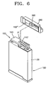
- FIG. 6 is an exploded view of a battery pack according to another embodiment of the present invention.
- the battery pack includes a bare cell 100, a PCM 150 mounted on the bare cell 100, an upper cover 260 connected to the bare cell 100 so as to accommodate the PCM 150.
- the upper cover 260 includes a protrusion 265 protruding downward to the PCM 150 to be engaged with an assembly position P of the PCM 150.
- the assembly position P of the upper cover 260 is determined by the engagement of the protrusion 265 with the PCM 150, and the upper cover 260 is fixed at the right position since the protrusion 265 acts to engage with the through hole 140'.
- a through-hole 140' may be formed at the assembly position P of the PCM 150, and the protrusion 265 is engaged with the through-hole 140'.
- the through-hole 140' functions as a path through which a welding apparatus W ( FIG. 3 ) passes and an assembly structure with which the protrusion 265 is engaged.
- the protrusion 265 may have a shape matching with the through-hole 140', for example a rectangular shape.
- FIG. 7 shows a protrusion 265 of the upper cover 260.
- the protrusion 265 has a rectangular shape with a long side 265a and a short side 265b.
- the long side 265a of the protrusion 265 acts to engage with the through-hole 140' in the second axis direction Z2 to regulate the assembly position of the upper cover 260.
- the short side 265b of the protrusion 265 acts to engage with the through-hole 140' in the first axis direction Z1 to regulate the assembly position of the upper cover 260.
- tolerance therebetween may be maintained within a predetermined range, thereby efficiently regulating the position of the upper cover 260.
- the protrusion 265 may have round portions R at corners thereof to reduce unnecessary interference between the protrusion 265 and the through-hole 140' during the assembly and to assist in locating the protrusion into the through-hole 140'.
- the upper cover 260 may have a binding force sufficient to be integrated with the bare cell 100 to form the battery pack.
- the protrusion 265 may be forced to be engaged with the through-hole 140' to provide a sufficient binding force.
- the binding force of the upper cover 260 may increase using an additional structure.
- a double-coated tape (not shown) may be interposed between the upper cover 260 and the PCM 150 to strongly assemble the upper cover 260 with the bare cell 100.
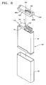
- FIG. 8 is an exploded perspective view of a battery pack according to another embodiment of the present invention.
- the battery pack includes a bare cell 100, a PCM 150 mounted on the bare cell 100, and an upper cover 360 connected to the bare cell 100 so as to accommodate the PCM 150.
- the PCM 150 is fixed on the bare cell 100 using spot welding, and the upper cover 360 is assembled onto the PCM 150.
- the upper cover 360 includes a protrusion 365 protruding downward to the PCM 150 to be engaged with an assembly position P of the PCM 150.
- the assembly position P of the upper cover 360 is determined by the engagement of the protrusion 365 with the PCM 150. Due to the tight coupling between the protrusion 365 and the through-hole 140', the assembly position of the upper cover 360 is regulated, and displacement of the upper cover 360 may be inhibited.
- a skirt 368 extending from the edge of a side of the upper cover 360 and covering a portion of a side of the bare cell 100 is disposed along the edge of the upper cover 360.
- the skirt 368 may extend from the long side 360a of the upper cover 360 to cover a portion of a side of the bare cell 100.
- the skirt 368 is used to strongly fix the upper cover 360.
- displacement of the upper cover 360 may be inhibited by the skirt 368 that is disposed to cover a portion of a side of the bare cell 100 and holds the upper cover 360 in place.
- the skirt 368 and the protrusion 365 are disposed at different positions in the upper cover 360 to determine the assembly position of the upper cover 360 and inhibit displacement of the upper cover 360 from the determined assembly position.
- the skirt 368 may be formed along the short side 360b of the upper cover 360, or along the long side 360a/ short side 360b.
- the outer surface of the bare cell 100 is surrounded by an insulating label sheet, or sleeve, 180 coated with an adhesive.
- the skirt 368 is also surrounded by the insulating label sheet 180, and thus the binding force between the upper cover 360 and the bare cell 100 may increase by the insulating label sheet 180.
- FIG. 9 is an exploded perspective view of a battery pack according to another embodiment of the present invention.
- the battery pack includes a bare cell 200, a PCM 150 mounted on the bare cell 200, and an upper cover 160 connected to the bare cell 200 so as to accommodate the PCM 150.
- the upper cover 160 and the PCM 150 are aligned by engaging the protrusion 165 of the upper cover 160 into a through-hole 140' of the PCM 150.
- a position determining unit 200' may be disposed at a contact portion between the PCM 150 and the bare cell 200 to align the PCM 150 and the bare cell 200.
- the position determining unit 200' may have a concave shape retracted from the upper surface of the bare cell 200.
- the position determining unit 200' is also referred to herein as a recess.
- the position determining unit 200' may be formed to match the second connecting member 132 at a contact position between the position determining unit 200' and the second connecting member 132 of the PCM 150. The displacement of the PCM 150 may be inhibited since the second connecting member 132 is inserted into the position determining unit 200', and the assembly may be easily conducted since the PCM 150 is fixed before performing an assembling process such as spot welding.
- the position determining unit 200' may also be disposed at the PCM 150 instead of at the bare cell 200.
- the position determining unit 200' may also be a pair disposed at the both bare cell 200 and the PCM 150 and matching with each other.
- Reference numeral 230 that is not described herein indicates a cap assembly.
- the position determining unit 200' may also be disposed in the cap assembly 230 forming the upper part of the bare cell 200.
Applications Claiming Priority (1)
| Application Number | Priority Date | Filing Date | Title |
|---|---|---|---|
| US25082809P | 2009-10-12 | 2009-10-12 |
Publications (2)
| Publication Number | Publication Date |
|---|---|
| EP2320491A1 EP2320491A1 (en) | 2011-05-11 |
| EP2320491B1 true EP2320491B1 (en) | 2013-07-31 |
Family
ID=43437247
Family Applications (1)
| Application Number | Title | Priority Date | Filing Date |
|---|---|---|---|
| EP10176881.0A Active EP2320491B1 (en) | 2009-10-12 | 2010-09-15 | Battery pack |
Country Status (5)
| Country | Link |
|---|---|
| US (1) | US9263724B2 (zh) |
| EP (1) | EP2320491B1 (zh) |
| JP (1) | JP5352560B2 (zh) |
| KR (1) | KR101156542B1 (zh) |
| CN (1) | CN102044651B (zh) |
Families Citing this family (22)
| Publication number | Priority date | Publication date | Assignee | Title |
|---|---|---|---|---|
| US9099726B2 (en) | 2010-01-19 | 2015-08-04 | Samsung Sdi Co., Ltd. | Secondary battery and method of fabricating the same |
| KR101250197B1 (ko) * | 2010-05-28 | 2013-04-03 | 주식회사 엘지화학 | 신규한 구조의 전지팩 |
| CN103080202B (zh) * | 2010-07-12 | 2014-09-24 | 巴斯夫股份公司 | 老化稳定的丙烯腈共聚物成型组合物 |
| JP5524105B2 (ja) * | 2011-02-14 | 2014-06-18 | 株式会社マキタ | 電動工具用バッテリ |
| KR20130016035A (ko) | 2011-08-04 | 2013-02-14 | 주식회사 엘지화학 | 신규한 구조의 이차전지 팩 |
| KR20130018478A (ko) * | 2011-08-09 | 2013-02-25 | 주식회사 엘지화학 | 신규한 구조의 이차전지 팩 |
| KR101433666B1 (ko) * | 2012-02-07 | 2014-08-25 | 주식회사 엘지화학 | 전지케이스 상의 미코팅 구간을 포함하는 전지셀의 제조방법 |
| KR101433664B1 (ko) * | 2012-02-07 | 2014-08-25 | 주식회사 엘지화학 | 하단면에 만입형 그루브가 형성되어 있는 구조의 각형 전지팩 |
| KR101365968B1 (ko) * | 2012-02-07 | 2014-02-24 | 주식회사 엘지화학 | 신규한 구조의 전지셀 제조방법 |
| DE102013108641A1 (de) * | 2012-08-16 | 2014-02-20 | Autoliv Development Ab | Vorrichtung zur Erzeugung von Gas zum Aufblasen eines Airbags |
| KR200472639Y1 (ko) * | 2012-09-26 | 2014-05-14 | 주식회사 이랜텍 | 브릿지형 접속플레이트를 갖는 결합구조가 단순화된 배터리팩 |
| US20140178715A1 (en) * | 2012-12-21 | 2014-06-26 | Samsung Sdi Co., Ltd. | Battery pack |
| KR101440891B1 (ko) * | 2013-01-30 | 2014-09-17 | 삼성에스디아이 주식회사 | 이차 전지 |
| USD740752S1 (en) * | 2014-01-30 | 2015-10-13 | Nikon Corporation | Battery |
| USD740226S1 (en) * | 2014-01-30 | 2015-10-06 | Nikon Corporation | Battery |
| KR101520391B1 (ko) * | 2014-02-11 | 2015-05-14 | 삼성에스디아이 주식회사 | 전지 팩 |
| WO2015167033A1 (ko) | 2014-04-29 | 2015-11-05 | 주식회사 엘지화학 | 보호회로모듈 고정부를 포함하는 전지팩 |
| DE102014222552A1 (de) | 2014-11-05 | 2016-05-12 | Robert Bosch Gmbh | Batteriezelle und Batteriesystem mit reversibel miteinander verbindbarer und voneinander lösbarer Komponenten |
| US10403869B2 (en) | 2015-04-13 | 2019-09-03 | Cps Technology Holdings, Llc | Adhesive tape for positioning battery cells in a battery module |
| KR102341400B1 (ko) * | 2015-05-06 | 2021-12-20 | 삼성에스디아이 주식회사 | 베터리 팩 |
| KR101863095B1 (ko) * | 2016-11-18 | 2018-05-31 | 삼성에스디아이 주식회사 | 배터리 팩의 제조장치 |
| KR102221780B1 (ko) * | 2017-05-04 | 2021-03-02 | 주식회사 엘지화학 | 배터리 팩 및 이의 제조방법 |
Family Cites Families (17)
| Publication number | Priority date | Publication date | Assignee | Title |
|---|---|---|---|---|
| KR100822188B1 (ko) * | 2001-10-24 | 2008-04-16 | 삼성에스디아이 주식회사 | 각형 이차전지 |
| WO2005078825A1 (en) * | 2004-02-13 | 2005-08-25 | Lg Chem, Ltd. | Battery pack of improved structure |
| KR100537538B1 (ko) | 2004-03-30 | 2005-12-16 | 삼성에스디아이 주식회사 | 리드 플레이트가 부착된 각형 이차 전지 |
| KR100614377B1 (ko) * | 2004-11-15 | 2006-08-21 | 삼성에스디아이 주식회사 | 리튬 이차전지 |
| JP5044934B2 (ja) | 2005-01-21 | 2012-10-10 | ソニー株式会社 | 電池パック |
| TWI308806B (en) | 2005-01-21 | 2009-04-11 | Sony Corp | Battery pack |
| KR100861714B1 (ko) | 2005-12-22 | 2008-10-06 | 주식회사 엘지화학 | 리벳을 이용한 무용접 방식의 전지팩 |
| EP3048657B1 (en) * | 2005-12-22 | 2017-10-25 | LG Chem, Ltd. | No-welding type battery pack using forced-inserting type rivet |
| KR100614278B1 (ko) | 2006-02-09 | 2006-08-22 | 주식회사 비티에스 | 이동통신단말기용 내장형 배터리팩 |
| KR100791551B1 (ko) | 2007-08-17 | 2008-01-07 | 주식회사 퓨처라인 | 보호회로모듈과 이를 포함하는 전지 및 상기보호회로모듈을 포함하는 전지 제조 방법 |
| JP5291322B2 (ja) | 2007-10-26 | 2013-09-18 | 日立マクセル株式会社 | 電池パック |
| KR100928120B1 (ko) | 2007-11-07 | 2009-11-24 | 삼성에스디아이 주식회사 | 이차 전지 |
| KR100947981B1 (ko) | 2007-11-12 | 2010-03-18 | 삼성에스디아이 주식회사 | 전지 팩 |
| KR101017911B1 (ko) | 2007-11-29 | 2011-03-04 | 주식회사 엘지화학 | 우수한 제조 공정성의 이차전지 팩 |
| EP2212940B1 (en) | 2007-11-23 | 2015-02-25 | LG Chem, Ltd. | Secondary battery pack providing excellent productivity and structural stability |
| BRPI0820355B1 (pt) | 2007-11-29 | 2021-04-20 | Lg Chem, Ltd | pacote de bateria secundária de estrutura compacta |
| KR100926717B1 (ko) | 2008-03-11 | 2009-11-13 | 주홍표 | 이동통신단말기용 내장형 배터리팩의 결합구조 |
-
2010
- 2010-08-31 US US12/872,939 patent/US9263724B2/en active Active
- 2010-09-13 KR KR1020100089456A patent/KR101156542B1/ko active IP Right Grant
- 2010-09-15 EP EP10176881.0A patent/EP2320491B1/en active Active
- 2010-10-08 JP JP2010228852A patent/JP5352560B2/ja active Active
- 2010-10-11 CN CN201010504287.3A patent/CN102044651B/zh active Active
Also Published As
| Publication number | Publication date |
|---|---|
| EP2320491A1 (en) | 2011-05-11 |
| KR20110040670A (ko) | 2011-04-20 |
| CN102044651B (zh) | 2015-03-25 |
| JP2011082171A (ja) | 2011-04-21 |
| US9263724B2 (en) | 2016-02-16 |
| US20110086243A1 (en) | 2011-04-14 |
| JP5352560B2 (ja) | 2013-11-27 |
| CN102044651A (zh) | 2011-05-04 |
| KR101156542B1 (ko) | 2012-06-20 |
Similar Documents
| Publication | Publication Date | Title |
|---|---|---|
| EP2320491B1 (en) | Battery pack | |
| EP2731174B1 (en) | Secondary battery pack | |
| KR102253021B1 (ko) | 퓨즈부를 갖는 이차 전지 및 전지 모듈 | |
| JP4558671B2 (ja) | 二次電池 | |
| US20040126650A1 (en) | Electrode assembly for lithium ion cell and lithium cell using the same | |
| US8822069B2 (en) | Battery pack | |
| EP2043177B1 (en) | Protective circuit board and battery pack using the same | |
| US8481183B2 (en) | Secondary battery | |
| EP2495794B1 (en) | Battery pack | |
| EP2731175A2 (en) | Secondary battery pack | |
| JP5190439B2 (ja) | 二次電池 | |
| KR20110038914A (ko) | 배터리 팩 및 그 제조 방법 | |
| US9099726B2 (en) | Secondary battery and method of fabricating the same | |
| KR20130025165A (ko) | 충방전이 가능한 배터리 팩 | |
| KR101303396B1 (ko) | 몰딩부를 구비한 이차 전지 | |
| KR102373537B1 (ko) | 전지 모듈 | |
| KR101453783B1 (ko) | 캡 조립체 및 이를 이용한 이차 전지 | |
| KR20170040988A (ko) | 이차전지 팩 | |
| KR101386168B1 (ko) | 충방전이 가능한 배터리 팩 | |
| KR101723261B1 (ko) | 전지셀의 보호회로모듈 용접용 지그 | |
| KR20170121953A (ko) | 보호회로모듈을 갖는 이차 전지 | |
| KR101264519B1 (ko) | 이차 전지 및 그 제조 방법 | |
| KR20090096954A (ko) | 보호회로가 영구적으로 부착된 전지 팩 |
Legal Events
| Date | Code | Title | Description |
|---|---|---|---|
| PUAI | Public reference made under article 153(3) epc to a published international application that has entered the european phase |
Free format text: ORIGINAL CODE: 0009012 |
|
| 17P | Request for examination filed |
Effective date: 20100915 |
|
| AK | Designated contracting states |
Kind code of ref document: A1 Designated state(s): AL AT BE BG CH CY CZ DE DK EE ES FI FR GB GR HR HU IE IS IT LI LT LU LV MC MK MT NL NO PL PT RO SE SI SK SM TR |
|
| AX | Request for extension of the european patent |
Extension state: BA ME RS |
|
| REG | Reference to a national code |
Ref country code: DE Ref legal event code: R079 Ref document number: 602010008988 Country of ref document: DE Free format text: PREVIOUS MAIN CLASS: H01M0002040000 Ipc: H01M0002340000 |
|
| RIC1 | Information provided on ipc code assigned before grant |
Ipc: H01M 2/34 20060101AFI20121213BHEP Ipc: H01M 2/10 20060101ALI20121213BHEP |
|
| GRAP | Despatch of communication of intention to grant a patent |
Free format text: ORIGINAL CODE: EPIDOSNIGR1 |
|
| GRAS | Grant fee paid |
Free format text: ORIGINAL CODE: EPIDOSNIGR3 |
|
| GRAA | (expected) grant |
Free format text: ORIGINAL CODE: 0009210 |
|
| AK | Designated contracting states |
Kind code of ref document: B1 Designated state(s): AL AT BE BG CH CY CZ DE DK EE ES FI FR GB GR HR HU IE IS IT LI LT LU LV MC MK MT NL NO PL PT RO SE SI SK SM TR |
|
| REG | Reference to a national code |
Ref country code: GB Ref legal event code: FG4D Ref country code: CH Ref legal event code: EP |
|
| REG | Reference to a national code |
Ref country code: AT Ref legal event code: REF Ref document number: 625095 Country of ref document: AT Kind code of ref document: T Effective date: 20130815 |
|
| RAP2 | Party data changed (patent owner data changed or rights of a patent transferred) |
Owner name: SAMSUNG SDI CO., LTD. |
|
| REG | Reference to a national code |
Ref country code: IE Ref legal event code: FG4D |
|
| REG | Reference to a national code |
Ref country code: DE Ref legal event code: R096 Ref document number: 602010008988 Country of ref document: DE Effective date: 20130926 |
|
| REG | Reference to a national code |
Ref country code: AT Ref legal event code: MK05 Ref document number: 625095 Country of ref document: AT Kind code of ref document: T Effective date: 20130731 |
|
| REG | Reference to a national code |
Ref country code: NL Ref legal event code: VDEP Effective date: 20130731 |
|
| REG | Reference to a national code |
Ref country code: LT Ref legal event code: MG4D |
|
| PG25 | Lapsed in a contracting state [announced via postgrant information from national office to epo] |
Ref country code: BE Free format text: LAPSE BECAUSE OF FAILURE TO SUBMIT A TRANSLATION OF THE DESCRIPTION OR TO PAY THE FEE WITHIN THE PRESCRIBED TIME-LIMIT Effective date: 20130731 Ref country code: LT Free format text: LAPSE BECAUSE OF FAILURE TO SUBMIT A TRANSLATION OF THE DESCRIPTION OR TO PAY THE FEE WITHIN THE PRESCRIBED TIME-LIMIT Effective date: 20130731 Ref country code: SE Free format text: LAPSE BECAUSE OF FAILURE TO SUBMIT A TRANSLATION OF THE DESCRIPTION OR TO PAY THE FEE WITHIN THE PRESCRIBED TIME-LIMIT Effective date: 20130731 Ref country code: CY Free format text: LAPSE BECAUSE OF FAILURE TO SUBMIT A TRANSLATION OF THE DESCRIPTION OR TO PAY THE FEE WITHIN THE PRESCRIBED TIME-LIMIT Effective date: 20130717 Ref country code: HR Free format text: LAPSE BECAUSE OF FAILURE TO SUBMIT A TRANSLATION OF THE DESCRIPTION OR TO PAY THE FEE WITHIN THE PRESCRIBED TIME-LIMIT Effective date: 20130731 Ref country code: AT Free format text: LAPSE BECAUSE OF FAILURE TO SUBMIT A TRANSLATION OF THE DESCRIPTION OR TO PAY THE FEE WITHIN THE PRESCRIBED TIME-LIMIT Effective date: 20130731 Ref country code: NO Free format text: LAPSE BECAUSE OF FAILURE TO SUBMIT A TRANSLATION OF THE DESCRIPTION OR TO PAY THE FEE WITHIN THE PRESCRIBED TIME-LIMIT Effective date: 20131031 Ref country code: IS Free format text: LAPSE BECAUSE OF FAILURE TO SUBMIT A TRANSLATION OF THE DESCRIPTION OR TO PAY THE FEE WITHIN THE PRESCRIBED TIME-LIMIT Effective date: 20131130 Ref country code: PT Free format text: LAPSE BECAUSE OF FAILURE TO SUBMIT A TRANSLATION OF THE DESCRIPTION OR TO PAY THE FEE WITHIN THE PRESCRIBED TIME-LIMIT Effective date: 20131202 |
|
| PG25 | Lapsed in a contracting state [announced via postgrant information from national office to epo] |
Ref country code: FI Free format text: LAPSE BECAUSE OF FAILURE TO SUBMIT A TRANSLATION OF THE DESCRIPTION OR TO PAY THE FEE WITHIN THE PRESCRIBED TIME-LIMIT Effective date: 20130731 Ref country code: SI Free format text: LAPSE BECAUSE OF FAILURE TO SUBMIT A TRANSLATION OF THE DESCRIPTION OR TO PAY THE FEE WITHIN THE PRESCRIBED TIME-LIMIT Effective date: 20130731 Ref country code: GR Free format text: LAPSE BECAUSE OF FAILURE TO SUBMIT A TRANSLATION OF THE DESCRIPTION OR TO PAY THE FEE WITHIN THE PRESCRIBED TIME-LIMIT Effective date: 20131101 Ref country code: LV Free format text: LAPSE BECAUSE OF FAILURE TO SUBMIT A TRANSLATION OF THE DESCRIPTION OR TO PAY THE FEE WITHIN THE PRESCRIBED TIME-LIMIT Effective date: 20130731 Ref country code: PL Free format text: LAPSE BECAUSE OF FAILURE TO SUBMIT A TRANSLATION OF THE DESCRIPTION OR TO PAY THE FEE WITHIN THE PRESCRIBED TIME-LIMIT Effective date: 20130731 Ref country code: NL Free format text: LAPSE BECAUSE OF FAILURE TO SUBMIT A TRANSLATION OF THE DESCRIPTION OR TO PAY THE FEE WITHIN THE PRESCRIBED TIME-LIMIT Effective date: 20130731 |
|
| PG25 | Lapsed in a contracting state [announced via postgrant information from national office to epo] |
Ref country code: CY Free format text: LAPSE BECAUSE OF FAILURE TO SUBMIT A TRANSLATION OF THE DESCRIPTION OR TO PAY THE FEE WITHIN THE PRESCRIBED TIME-LIMIT Effective date: 20130731 |
|
| PG25 | Lapsed in a contracting state [announced via postgrant information from national office to epo] |
Ref country code: SK Free format text: LAPSE BECAUSE OF FAILURE TO SUBMIT A TRANSLATION OF THE DESCRIPTION OR TO PAY THE FEE WITHIN THE PRESCRIBED TIME-LIMIT Effective date: 20130731 Ref country code: EE Free format text: LAPSE BECAUSE OF FAILURE TO SUBMIT A TRANSLATION OF THE DESCRIPTION OR TO PAY THE FEE WITHIN THE PRESCRIBED TIME-LIMIT Effective date: 20130731 Ref country code: CZ Free format text: LAPSE BECAUSE OF FAILURE TO SUBMIT A TRANSLATION OF THE DESCRIPTION OR TO PAY THE FEE WITHIN THE PRESCRIBED TIME-LIMIT Effective date: 20130731 Ref country code: RO Free format text: LAPSE BECAUSE OF FAILURE TO SUBMIT A TRANSLATION OF THE DESCRIPTION OR TO PAY THE FEE WITHIN THE PRESCRIBED TIME-LIMIT Effective date: 20130731 Ref country code: DK Free format text: LAPSE BECAUSE OF FAILURE TO SUBMIT A TRANSLATION OF THE DESCRIPTION OR TO PAY THE FEE WITHIN THE PRESCRIBED TIME-LIMIT Effective date: 20130731 Ref country code: MC Free format text: LAPSE BECAUSE OF FAILURE TO SUBMIT A TRANSLATION OF THE DESCRIPTION OR TO PAY THE FEE WITHIN THE PRESCRIBED TIME-LIMIT Effective date: 20130731 |
|
| PG25 | Lapsed in a contracting state [announced via postgrant information from national office to epo] |
Ref country code: IT Free format text: LAPSE BECAUSE OF FAILURE TO SUBMIT A TRANSLATION OF THE DESCRIPTION OR TO PAY THE FEE WITHIN THE PRESCRIBED TIME-LIMIT Effective date: 20130731 Ref country code: ES Free format text: LAPSE BECAUSE OF FAILURE TO SUBMIT A TRANSLATION OF THE DESCRIPTION OR TO PAY THE FEE WITHIN THE PRESCRIBED TIME-LIMIT Effective date: 20130731 |
|
| PLBE | No opposition filed within time limit |
Free format text: ORIGINAL CODE: 0009261 |
|
| STAA | Information on the status of an ep patent application or granted ep patent |
Free format text: STATUS: NO OPPOSITION FILED WITHIN TIME LIMIT |
|
| REG | Reference to a national code |
Ref country code: IE Ref legal event code: MM4A |
|
| 26N | No opposition filed |
Effective date: 20140502 |
|
| PG25 | Lapsed in a contracting state [announced via postgrant information from national office to epo] |
Ref country code: IE Free format text: LAPSE BECAUSE OF NON-PAYMENT OF DUE FEES Effective date: 20130915 |
|
| REG | Reference to a national code |
Ref country code: DE Ref legal event code: R097 Ref document number: 602010008988 Country of ref document: DE Effective date: 20140502 |
|
| REG | Reference to a national code |
Ref country code: CH Ref legal event code: PL |
|
| PG25 | Lapsed in a contracting state [announced via postgrant information from national office to epo] |
Ref country code: SM Free format text: LAPSE BECAUSE OF FAILURE TO SUBMIT A TRANSLATION OF THE DESCRIPTION OR TO PAY THE FEE WITHIN THE PRESCRIBED TIME-LIMIT Effective date: 20130731 |
|
| PG25 | Lapsed in a contracting state [announced via postgrant information from national office to epo] |
Ref country code: MT Free format text: LAPSE BECAUSE OF FAILURE TO SUBMIT A TRANSLATION OF THE DESCRIPTION OR TO PAY THE FEE WITHIN THE PRESCRIBED TIME-LIMIT Effective date: 20130731 Ref country code: TR Free format text: LAPSE BECAUSE OF FAILURE TO SUBMIT A TRANSLATION OF THE DESCRIPTION OR TO PAY THE FEE WITHIN THE PRESCRIBED TIME-LIMIT Effective date: 20130731 |
|
| PG25 | Lapsed in a contracting state [announced via postgrant information from national office to epo] |
Ref country code: LI Free format text: LAPSE BECAUSE OF NON-PAYMENT OF DUE FEES Effective date: 20140930 Ref country code: HU Free format text: LAPSE BECAUSE OF FAILURE TO SUBMIT A TRANSLATION OF THE DESCRIPTION OR TO PAY THE FEE WITHIN THE PRESCRIBED TIME-LIMIT; INVALID AB INITIO Effective date: 20100915 Ref country code: MK Free format text: LAPSE BECAUSE OF FAILURE TO SUBMIT A TRANSLATION OF THE DESCRIPTION OR TO PAY THE FEE WITHIN THE PRESCRIBED TIME-LIMIT Effective date: 20130731 Ref country code: BG Free format text: LAPSE BECAUSE OF FAILURE TO SUBMIT A TRANSLATION OF THE DESCRIPTION OR TO PAY THE FEE WITHIN THE PRESCRIBED TIME-LIMIT Effective date: 20130731 Ref country code: CH Free format text: LAPSE BECAUSE OF NON-PAYMENT OF DUE FEES Effective date: 20140930 Ref country code: LU Free format text: LAPSE BECAUSE OF NON-PAYMENT OF DUE FEES Effective date: 20130915 |
|
| REG | Reference to a national code |
Ref country code: FR Ref legal event code: PLFP Year of fee payment: 7 |
|
| REG | Reference to a national code |
Ref country code: FR Ref legal event code: PLFP Year of fee payment: 8 |
|
| REG | Reference to a national code |
Ref country code: FR Ref legal event code: PLFP Year of fee payment: 9 |
|
| PG25 | Lapsed in a contracting state [announced via postgrant information from national office to epo] |
Ref country code: AL Free format text: LAPSE BECAUSE OF FAILURE TO SUBMIT A TRANSLATION OF THE DESCRIPTION OR TO PAY THE FEE WITHIN THE PRESCRIBED TIME-LIMIT Effective date: 20130731 |
|
| REG | Reference to a national code |
Ref country code: DE Ref legal event code: R079 Ref document number: 602010008988 Country of ref document: DE Free format text: PREVIOUS MAIN CLASS: H01M0002340000 Ipc: H01M0050572000 |
|
| P01 | Opt-out of the competence of the unified patent court (upc) registered |
Effective date: 20230528 |
|
| PGFP | Annual fee paid to national office [announced via postgrant information from national office to epo] |
Ref country code: GB Payment date: 20230824 Year of fee payment: 14 |
|
| PGFP | Annual fee paid to national office [announced via postgrant information from national office to epo] |
Ref country code: FR Payment date: 20230911 Year of fee payment: 14 Ref country code: DE Payment date: 20230830 Year of fee payment: 14 |