EP2320486A2 - Connection between a thermoelectric element and a heat exchanger - Google Patents
Connection between a thermoelectric element and a heat exchanger Download PDFInfo
- Publication number
- EP2320486A2 EP2320486A2 EP10014232A EP10014232A EP2320486A2 EP 2320486 A2 EP2320486 A2 EP 2320486A2 EP 10014232 A EP10014232 A EP 10014232A EP 10014232 A EP10014232 A EP 10014232A EP 2320486 A2 EP2320486 A2 EP 2320486A2
- Authority
- EP
- European Patent Office
- Prior art keywords
- heat exchanger
- thermoelectric element
- heat
- connection
- heat conducting
- Prior art date
- Legal status (The legal status is an assumption and is not a legal conclusion. Google has not performed a legal analysis and makes no representation as to the accuracy of the status listed.)
- Withdrawn
Links
Images
Classifications
-
- F—MECHANICAL ENGINEERING; LIGHTING; HEATING; WEAPONS; BLASTING
- F01—MACHINES OR ENGINES IN GENERAL; ENGINE PLANTS IN GENERAL; STEAM ENGINES
- F01N—GAS-FLOW SILENCERS OR EXHAUST APPARATUS FOR MACHINES OR ENGINES IN GENERAL; GAS-FLOW SILENCERS OR EXHAUST APPARATUS FOR INTERNAL COMBUSTION ENGINES
- F01N3/00—Exhaust or silencing apparatus having means for purifying, rendering innocuous, or otherwise treating exhaust
- F01N3/02—Exhaust or silencing apparatus having means for purifying, rendering innocuous, or otherwise treating exhaust for cooling, or for removing solid constituents of, exhaust
- F01N3/05—Exhaust or silencing apparatus having means for purifying, rendering innocuous, or otherwise treating exhaust for cooling, or for removing solid constituents of, exhaust by means of air, e.g. by mixing exhaust with air
- F01N3/055—Exhaust or silencing apparatus having means for purifying, rendering innocuous, or otherwise treating exhaust for cooling, or for removing solid constituents of, exhaust by means of air, e.g. by mixing exhaust with air without contact between air and exhaust gases
-
- F—MECHANICAL ENGINEERING; LIGHTING; HEATING; WEAPONS; BLASTING
- F01—MACHINES OR ENGINES IN GENERAL; ENGINE PLANTS IN GENERAL; STEAM ENGINES
- F01N—GAS-FLOW SILENCERS OR EXHAUST APPARATUS FOR MACHINES OR ENGINES IN GENERAL; GAS-FLOW SILENCERS OR EXHAUST APPARATUS FOR INTERNAL COMBUSTION ENGINES
- F01N5/00—Exhaust or silencing apparatus combined or associated with devices profiting from exhaust energy
- F01N5/02—Exhaust or silencing apparatus combined or associated with devices profiting from exhaust energy the devices using heat
- F01N5/025—Exhaust or silencing apparatus combined or associated with devices profiting from exhaust energy the devices using heat the device being thermoelectric generators
-
- H—ELECTRICITY
- H10—SEMICONDUCTOR DEVICES; ELECTRIC SOLID-STATE DEVICES NOT OTHERWISE PROVIDED FOR
- H10N—ELECTRIC SOLID-STATE DEVICES NOT OTHERWISE PROVIDED FOR
- H10N10/00—Thermoelectric devices comprising a junction of dissimilar materials, i.e. devices exhibiting Seebeck or Peltier effects
- H10N10/10—Thermoelectric devices comprising a junction of dissimilar materials, i.e. devices exhibiting Seebeck or Peltier effects operating with only the Peltier or Seebeck effects
- H10N10/13—Thermoelectric devices comprising a junction of dissimilar materials, i.e. devices exhibiting Seebeck or Peltier effects operating with only the Peltier or Seebeck effects characterised by the heat-exchanging means at the junction
-
- F—MECHANICAL ENGINEERING; LIGHTING; HEATING; WEAPONS; BLASTING
- F28—HEAT EXCHANGE IN GENERAL
- F28F—DETAILS OF HEAT-EXCHANGE AND HEAT-TRANSFER APPARATUS, OF GENERAL APPLICATION
- F28F13/00—Arrangements for modifying heat-transfer, e.g. increasing, decreasing
- F28F2013/005—Thermal joints
- F28F2013/006—Heat conductive materials
-
- Y—GENERAL TAGGING OF NEW TECHNOLOGICAL DEVELOPMENTS; GENERAL TAGGING OF CROSS-SECTIONAL TECHNOLOGIES SPANNING OVER SEVERAL SECTIONS OF THE IPC; TECHNICAL SUBJECTS COVERED BY FORMER USPC CROSS-REFERENCE ART COLLECTIONS [XRACs] AND DIGESTS
- Y02—TECHNOLOGIES OR APPLICATIONS FOR MITIGATION OR ADAPTATION AGAINST CLIMATE CHANGE
- Y02T—CLIMATE CHANGE MITIGATION TECHNOLOGIES RELATED TO TRANSPORTATION
- Y02T10/00—Road transport of goods or passengers
- Y02T10/10—Internal combustion engine [ICE] based vehicles
- Y02T10/12—Improving ICE efficiencies
Definitions
- thermoelectric element Connection between a thermoelectric element and a heat exchanger
- the present invention relates to a connection between a thermoelectric element and a heat exchanger, wherein the thermoelectric element has a ceramic carrier layer on the outside and the heat exchanger has a heat exchanger wall.
- thermoelectric generator units are arranged in an exhaust path of an internal combustion engine in order to recover energy from the exhaust gas entrained by exhaust gases.
- thermocouples are arranged in an exhaust gas passage. Due to the exhaust gas flow and the connection of the exhaust pipe to the environment creates a temperature difference. Thermoelectric elements convert using the Seebeck effect converts the temperature difference directly into electrical energy.
- thermoelectric element So that a temperature difference can occur at the thermoelectric element, this has a hot and a cold side.
- a corresponding thickness of the individual elements In order to maintain a corresponding temperature gradient in the operation of the thermoelectric element, a corresponding thickness of the individual elements is necessary. In the construction, therefore, usually a thin-film technology or a film technology is used, but can not work optimally in an exhaust system in which high temperature differences prevail.
- thermoelectric element In order to avoid an electrical short circuit and to achieve a corresponding mechanical stability, the top and bottom of the thermoelectric element is fixed by means of ceramic plates.
- the ceramic plates then form a hot side on the side facing the exhaust gas line and a cold side on the side facing away from the exhaust gas line.
- thermoelectric elements In the production of a module with thermoelectric elements, the individual modules are pressed and clamped directly with the hot or cold side in the or surrounding components.
- thermoelectric modules In the field of energy recovery from an exhaust system in the motor vehicle several thermoelectric modules are interconnected. These are placed evenly on a plane of a single component. In order to be able to realize corresponding heat transfers and uniform compressions, the surfaces of the individual components have a surface quality in the range of approximately 20 ⁇ m. This creates a high production cost, which is associated with a high cost.
- thermoelectric generator module On the side of the thermoelectric generator module, it is additionally disadvantageous that the ceramic support layer of the hot or cold side with respect on the material components used can not have a required surface quality for the most part.
- the individual assemblies are pressed together under high pressure and then braced. In this case, impermissible residual stresses occur in the individual components, in particular in the thermoelectric elements, which decisively reduce the service life of the components.
- the object of the present invention is therefore to provide thermoelectric components with a heat exchanger which realize a consistently high manufacturing quality as well as a simple production process and a high heat transfer to improve the overall efficiency.
- thermoelectric elements no longer have to be pressed with high forces, as a result of which unacceptable residual stresses are avoided.
- the cohesive connection ensures a consistently high heat transfer between the ceramic carrier layer and the heat exchanger wall by the heat conducting means.
- thermoelectric elements Another advantage of the heat-conducting is that vehicle-side vibrations that are transmitted to the system by the operation of the internal combustion engine or the driving on the road, transmitted in accordance with attenuated become. This also increases the fatigue strength of a system with thermoelectric elements.
- the heat conduction is formed as a homogeneous heat conduction layer.
- a homogeneous heat conduction layer is to be understood as a molecular structure of the materials used which remains constant in all regions of the heat conduction layer.
- a high heat transfer coefficient is achieved at the border crossings of the ceramic carrier layer to the heat conduction layer and the heat conduction layer to the heat exchanger wall.
- the heat-conducting medium has a thermal conductivity of more than 10 W / mK.
- the high thermal conductivity allows good heat dissipation, so that there is always a temperature difference in the thermoelectric components during the entire operating period. The temperature difference in turn causes a voltage generation due to the Seebeck effect.
- the heat conducting medium is formed as an alloy comprising constituents of gallium (Ga) and indium (In).
- Gallium and indium can be combined with both stainless steel and ceramics and also in itself.
- a thermal conduction agent comprising the aforementioned alloying ingredients enters into the boundary zones of the ceramic carrier layer and the heat exchanger wall.
- the compounds are in the form of bridge formations via oxygen atoms, mechanical retention and cold diffusion. They are used both for adhesion in the border zones and for heat conduction.
- Indium ensures a low surface tension and thus a good wetting ability for other metals, glass or ceramic materials. It distorts the lattices of the alloy and thereby improves the mechanical properties. Indium forms a yellow adhesive oxide, which contributes to the adhesion of ceramic materials to metals. Here, the oxidation behavior contributes significantly to the metal-ceramic composite.
- Gallium lowers the melting temperature of the alloy and thus additionally improves the flowability and mold filling capacity of the alloy.
- the alloy additionally tin (Sn) as an alloying ingredient.
- Tin reduces carbon uptake and ensures that the steel alloys to be joined are not decarburized.
- tin promotes the adhesion oxide formation of the components gallium and indium. As a result, a higher strength is brought about with the aforementioned alloying ingredients.
- the alloy preferably has a proportion of 60-80% gallium, 10-30% indium and 1-20% tin, as well as other constituents of other substances, for example bismuth or antimony.
- the alloying constituents are important for setting a specific melting temperature.
- the thermal conductivity material properties produced by the alloying ingredients must also be selected from the aspect of processing temperature and operating temperature range. Galinstan or sodium are preferably used as heat transfer agents.
- the heat exchanger wall is formed from a metallic carrier substrate.
- the carrier substrate consists of an austenitic stainless steel alloy.
- the exhaust of a vehicle has corrosive properties and a broad spectrum in both composition and operating temperatures.
- a metallic material, in particular a stainless steel alloy therefore offers a particularly good protective effect against influences by the exhaust gas combined with a consistently good and high Thermal conductivity.
- a sufficient heat transfer from the exhaust gas flow into the thermoelectric element can be promoted during the entire spectrum of possible operating points.
- the heat conducting means is formed as solder.
- soldering a correspondingly full-surface metallized ceramic carrier layer is advantageous.
- solder joints are conceivable.
- a brazing alloy or a soft solder can be used with respect to the respective operating temperature or else an active solder which can be used at a high operating temperature. In this case, no metallization of the ceramic carrier layer for entering into a cohesive connection with the solder would be necessary.
- the thermoelectric element is designed as a thermoelectric generator.
- the generator consists of a plurality of thermoelectric elements which are electrically connected to each other in series or in parallel. In order to produce a corresponding temperature gradient and to be able to keep in operation, a corresponding thickness of the individual elements is necessary.
- the thus constructed thermoelectric generator has on its top and bottom ceramic support plates, which then form a hot and a cold side. Between the hot and cold side, the temperature difference arises, which in turn generates an electrical voltage through the Seebeck effect.
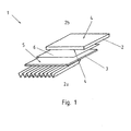
- FIG. 1 shows a compound 1 of a thermoelectric element 2 with a heat exchanger 3.
- the thermoelectric element 2 has on the outside ceramic carrier layers 4. With reference to the image plane, the underside of the thermoelectric element 2 forms a hot side 2a, the upper side of the thermoelectric element 2 forms a cold side 2b.
- the heat exchanger 3 is formed with a heat exchanger 5 wall.
- the heat exchanger wall 5 adjoins the hot side 2a of the thermoelectric element 2.
- a heat conducting means 6 is arranged between the heat exchanger wall 5 and the ceramic carrier layer 4 of the hot side 2a.
- the heat conducting means 6 connects the ceramic carrier layer 4 and the heat exchanger wall 5 cohesively. It forms a homogeneous heat conduction layer. Via the heat conduction layer, a heat flow can pass from the heat exchanger 3 into the thermoelectric element 2.
- the heat conducting means 6 preferably has the alloying elements gallium (Ga), indium (In) and tin (Sn).
- the alloy thus prepared enters into contact with the heat exchanger wall 5 and with the ceramic carrier layer 4.
- the heat exchanger wall 5 may be formed as a metallic carrier substrate or as austenitic stainless steel alloy.
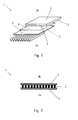
- FIG. 2 shows a sectional view through a thermoelectric generator 7.
- thermoelectric elements 2 are connected in parallel or connected in series.
- the elements connected in this way are bounded by two ceramic carrier layers 4. Between the ceramic carrier layers 4 creates a temperature difference.
- thermoelectric generator 7 On one side of the thermoelectric generator 7, a hot side 2a is produced by the application during operation, and a cold side 2b is formed on the side opposite the hot side 2a.
Abstract
Description
Die vorliegende Erfindung betrifft eine Verbindung zwischen einem thermoelektrischen Element und einem Wärmetauscher, wobei das thermoelektrische Element außenseitig eine Keramikträgerschicht aufweist und der Wärmetauscher eine Wärmetauscherwandung aufweist.The present invention relates to a connection between a thermoelectric element and a heat exchanger, wherein the thermoelectric element has a ceramic carrier layer on the outside and the heat exchanger has a heat exchanger wall.
Aus dem Stand der Technik sind Abgaswärmerückgewinnungssysteme bekannt. Hierbei werden thermoelektrische Generatoreneinheiten in einem Abgasweg eines Verbrennungsmotors angeordnet, um Energie aus der von Abgasen mitgeführten Abgaswärme zurück zu gewinnen.Exhaust heat recovery systems are known in the art. In this case, thermoelectric generator units are arranged in an exhaust path of an internal combustion engine in order to recover energy from the exhaust gas entrained by exhaust gases.
Bei den aus dem Stand der Technik bekannten Verfahren werden Thermoelemente in einem Abgasdurchlass angeordnet. Durch den Abgasstrom und die Verbindung des Abgasrohres zur Umgebung entsteht eine Temperaturdifferenz. Thermoelektrische Elemente wandeln mithilfe des Seebeck-Effekts die vorliegende Temperaturdifferenz direkt in elektrische Energie um.In the methods known from the prior art thermocouples are arranged in an exhaust gas passage. Due to the exhaust gas flow and the connection of the exhaust pipe to the environment creates a temperature difference. Thermoelectric elements convert using the Seebeck effect converts the temperature difference directly into electrical energy.
Damit an dem thermoelektrischen Element eine Temperaturdifferenz auftreten kann, verfügt dieses über eine Heiß- und über eine Kaltseite. Um einen entsprechenden Temperaturgradienten im Betrieb des thermoelektrischen Elements halten zu können, ist eine entsprechende Dicke der einzelnen Elemente notwendig. Im Aufbau wird daher meistens eine Dünnschichttechnologie oder eine Folientechnik eingesetzt, die jedoch in einem Abgasstrang, in dem hohe Temperaturdifferenzen herrschen, nicht optimal arbeiten kann.So that a temperature difference can occur at the thermoelectric element, this has a hot and a cold side. In order to maintain a corresponding temperature gradient in the operation of the thermoelectric element, a corresponding thickness of the individual elements is necessary. In the construction, therefore, usually a thin-film technology or a film technology is used, but can not work optimally in an exhaust system in which high temperature differences prevail.
Um einen elektrischen Kurzschluss zu vermeiden und eine entsprechende mechanische Stabilität zu realisieren, wird die Ober- und Unterseite des thermoelektrischen Elements mithilfe von keramischen Platten fixiert. Durch die keramischen Platten werden dann auf der zum Abgasstrang hingewandten Seite eine Heißseite und auf der dem Abgasstrang abgewandten Seite eine Kaltseite gebildet.In order to avoid an electrical short circuit and to achieve a corresponding mechanical stability, the top and bottom of the thermoelectric element is fixed by means of ceramic plates. The ceramic plates then form a hot side on the side facing the exhaust gas line and a cold side on the side facing away from the exhaust gas line.
Bei der Produktion einer Baugruppe mit thermoelektrischen Elementen werden die einzelnen Baugruppen direkt mit der Heiß- bzw. Kaltseite in das oder die umliegenden Bauteile gepresst und verspannt.In the production of a module with thermoelectric elements, the individual modules are pressed and clamped directly with the hot or cold side in the or surrounding components.
Im Bereich der Energierückgewinnung aus einem Abgasstrang im Kraftfahrzeug werden mehrere thermoelektrische Baugruppen miteinander verschaltet. Diese werden gleichmäßig auf eine plane Ebene eines einzelnen Bauteils gebracht. Um entsprechende Wärmeübergänge und gleichmäßige Verpressungen realisieren zu können, weisen die Oberflächen der einzelnen Bauelemente eine Oberflächengüte im Bereich von ca. 20 µm auf. Dadurch entsteht ein hoher Fertigungsaufwand, der mit einem hohen Kostenaufwand verbunden ist.In the field of energy recovery from an exhaust system in the motor vehicle several thermoelectric modules are interconnected. These are placed evenly on a plane of a single component. In order to be able to realize corresponding heat transfers and uniform compressions, the surfaces of the individual components have a surface quality in the range of approximately 20 μm. This creates a high production cost, which is associated with a high cost.
Auf der Seite des thermoelektrischen Generatorenmoduls ist es zusätzlich von Nachteil, dass die keramische Trägerschicht der Heiß- bzw. Kaltseite in Bezug auf die eingesetzte Werkstoffkomponenten eine geforderte Oberflächengüte größtenteils nicht aufweisen kann. Um dem entgegenzuwirken und im Rahmen der Fertigungstolleranzen konstant hohe Wärmeübergänge zu realisieren, werden die einzelnen Baugruppen mit hohem Druck verpresst und anschließend verspannt. Hierbei treten unzulässige Eigenspannungen in den einzelnen Bauteilen, insbesondere in den thermoelektrischen Elementen auf, die die Lebensdauer der Bauelemente entscheidend verringern.On the side of the thermoelectric generator module, it is additionally disadvantageous that the ceramic support layer of the hot or cold side with respect on the material components used can not have a required surface quality for the most part. To counteract this and to realize constant high heat transfer within the scope of the production tolerances, the individual assemblies are pressed together under high pressure and then braced. In this case, impermissible residual stresses occur in the individual components, in particular in the thermoelectric elements, which decisively reduce the service life of the components.
Die Aufgabe der vorliegenden Erfindung ist es daher thermoelektrische Bauelemente mit einem Wärmetauscher zur Verfügung zu stellen, die eine gleichbleibend hohe Fertigungsqualität sowie einen einfachen Fertigungsprozess und einen hohen Wärmeübergang zur Verbesserung des Gesamtwirkungsgrads realisieren.The object of the present invention is therefore to provide thermoelectric components with a heat exchanger which realize a consistently high manufacturing quality as well as a simple production process and a high heat transfer to improve the overall efficiency.
Die vorliegende Aufgabe wird durch eine Verbindung gemäß den Merkmalen des Patentanspruchs 1 gelöst. Daraus ergibt sich, dass zwischen der Keramikträgerschicht und der Wärmetauscherwandung ein Wärmeleitmittel angeordnet ist, welches die Keramikträgerschicht und die Wärmetauscherwandung stoffschlüssig verbindet.The present object is achieved by a compound according to the features of
Vorteilfhafte Ausgestaltungen und Weiterbildungen des grundsätzlichen Erfindungsgedankens sind Gegenstand der abhängigen Ansprüche 2 bis 9.Advantageous embodiments and further developments of the basic concept of the invention are the subject of the
Durch diesen Lösungsansatz müssen thermoelektrische Elemente nicht mehr mit hohen Kräften angepresst werden, in der Folge werden unzulässige Eigenspannungen vermieden.Due to this approach, thermoelectric elements no longer have to be pressed with high forces, as a result of which unacceptable residual stresses are avoided.
Durch die stoffschlüssige Verbindung wird ein gleichbleibend hoher Wärmeübergang zwischen der Keramikträgerschicht und der Wärmetauscherwandung durch das Wärmeleitmittel sichergestellt.The cohesive connection ensures a consistently high heat transfer between the ceramic carrier layer and the heat exchanger wall by the heat conducting means.
Ein weiterer Vorteil des Wärmeleitmittels ist, dass fahrzeugseitige Vibrationen, die durch den Betrieb des Verbrennungsmotors bzw. den Fahrbetrieb über die Straße auf das System übertragen werden, entsprechend gedämpft übertragen werden. Hierdurch erhöht sich ebenfalls die Dauerfestigkeit eines Systems mit thermoelektrischen Elementen.Another advantage of the heat-conducting is that vehicle-side vibrations that are transmitted to the system by the operation of the internal combustion engine or the driving on the road, transmitted in accordance with attenuated become. This also increases the fatigue strength of a system with thermoelectric elements.
Vorzugsweise ist das Wärmeleitmittel als homogene Wärmeleitungsschicht ausgebildet. Hierbei ist unter einer homogenen Wärmeleitungsschicht eine in allen Bereichen der Wärmeleitungsschicht gleichbleibende Molekülstruktur der eingesetzten Werkstoffe zu verstehen. An den Grenzübergängen von Keramikträgerschicht zu Wärmeleitungsschicht und Wärmeleitungsschicht zu Wärmetauscherwandung wird somit ein hoher Wärmeübergangskoeffizient erreicht.Preferably, the heat conduction is formed as a homogeneous heat conduction layer. In this case, a homogeneous heat conduction layer is to be understood as a molecular structure of the materials used which remains constant in all regions of the heat conduction layer. Thus, a high heat transfer coefficient is achieved at the border crossings of the ceramic carrier layer to the heat conduction layer and the heat conduction layer to the heat exchanger wall.
In einer weiteren vorteilhaften Ausbildung weist das Wärmeleitmittel eine Wärmeleitfähigkeit von mehr als 10 W/mK auf. Die hohe Wärmeleitfähigkeit ermöglicht einen guten Wärmeabtransport, so dass während der gesamten Betriebsdauer stets eine Temperaturdifferenz in den thermoelektrischen Bauelementen gegeben ist. Die Temperaturdifferenz wiederum bedingt eine Spannungserzeugung auf Grund des Seebeck-Effekts.In a further advantageous embodiment, the heat-conducting medium has a thermal conductivity of more than 10 W / mK. The high thermal conductivity allows good heat dissipation, so that there is always a temperature difference in the thermoelectric components during the entire operating period. The temperature difference in turn causes a voltage generation due to the Seebeck effect.
Vorzugsweise ist das Wärmeleitmittel als Legierung ausgebildet, die Bestandteile von Gallium (Ga) und Indium (In) aufweist. Gallium und Indium können Verbindungen sowohl mit Edelstahl als auch mit Keramik und zusätzlich auch in sich eingehen. Ein Wärmeleitmittel, dass die zuvor genannten Legierungsbestandteile aufweist, geht in den Grenzzonen der Keramikträgerschicht und der Wärmetauscherwandung Verbindungen ein. Die Verbindungen sind in Form von Brückenbildungen über Sauerstoffatome, mechanischer Retention und Kaltdiffusion ausgebildet. Sie werden sowohl zur Anhaftung in den Grenzzonen als auch zur Wärmeleitung genutzt.Preferably, the heat conducting medium is formed as an alloy comprising constituents of gallium (Ga) and indium (In). Gallium and indium can be combined with both stainless steel and ceramics and also in itself. A thermal conduction agent comprising the aforementioned alloying ingredients enters into the boundary zones of the ceramic carrier layer and the heat exchanger wall. The compounds are in the form of bridge formations via oxygen atoms, mechanical retention and cold diffusion. They are used both for adhesion in the border zones and for heat conduction.
Im Gitter herrscht somit eine Mischbildung aus Atombindungs- und lonenbindungsanteilen und einem geringen metallischen Bindungsanteil.In the lattice, there is thus a mixture of atomic bonding and ion-binding fractions and a small amount of metallic bonding.
Dabei sorgt Indium für eine geringe Oberflächenspannung und somit ein gutes Benetzungsvermögen für andere Metalle, Glas oder Keramikmassen. Es verzerrt die Gitter der Legierung und bewirkt dadurch eine Verbesserung der mechanischen Eigenschaften. Indium bildet ein gelbes Haftoxid, das zum Anhaften keramischer Massen an Metallen beiträgt. Hierbei trägt das Oxidationsverhalten wesentlich zum Metall-Keramik-Verbund bei.Indium ensures a low surface tension and thus a good wetting ability for other metals, glass or ceramic materials. It distorts the lattices of the alloy and thereby improves the mechanical properties. Indium forms a yellow adhesive oxide, which contributes to the adhesion of ceramic materials to metals. Here, the oxidation behavior contributes significantly to the metal-ceramic composite.
Gallium senkt die Schmelztemperatur der Legierung und verbessert so zusätzlich die Fließfähigkeit und das Formfüllvermögen der Legierung.Gallium lowers the melting temperature of the alloy and thus additionally improves the flowability and mold filling capacity of the alloy.
In einer besonders bevorzugten Ausführungsvariante weist die Legierung zusätzlich Zinn (Sn) als Legierungsbestandteil auf. Zinn verringert die Kohlenstoffaufnahme und sorgt dafür, dass die zu verbindenden Stahllegierungen nicht entkohlt werden. Weiterhin fördert Zinn die Haftoxidbildung der Bestandteile Gallium und Indium. Hierdurch wird eine höhere Festigkeit mit den zuvor benannten Legierungsbestandteilen herbeigeführt.In a particularly preferred embodiment, the alloy additionally tin (Sn) as an alloying ingredient. Tin reduces carbon uptake and ensures that the steel alloys to be joined are not decarburized. Furthermore, tin promotes the adhesion oxide formation of the components gallium and indium. As a result, a higher strength is brought about with the aforementioned alloying ingredients.
Die Legierung weist bevorzugt einen Anteil von 60 - 80% Gallium, 10 - 30% Indium und 1 - 20% Zinn auf, sowie weitere Bestandteile von anderen Stoffen, zum Beispiel Wismut oder Antimohn. Die Legierungsbestandteile sind wichtig für die Einstellung einer bestimmten Schmelztemperatur. Die durch die Legierungsbestandteile hergestellten Werkstoffeigenschaften des Wärmeleitmittels müssen ebenfalls unter dem Aspekt der Verarbeitungstemperatur und des Betriebstemperaturbereichs ausgewählt werden. Galinstan oder Natrium werden dabei bevorzugt als Wärmeleitmittel eingesetzt.The alloy preferably has a proportion of 60-80% gallium, 10-30% indium and 1-20% tin, as well as other constituents of other substances, for example bismuth or antimony. The alloying constituents are important for setting a specific melting temperature. The thermal conductivity material properties produced by the alloying ingredients must also be selected from the aspect of processing temperature and operating temperature range. Galinstan or sodium are preferably used as heat transfer agents.
Vorzugsweise ist die Wärmetauscherwandung aus einem metallischen Trägersubstrat ausgebildet.Preferably, the heat exchanger wall is formed from a metallic carrier substrate.
Besonders bevorzugt besteht das Trägersubstrat aus einer austenitischen Edelstahllegierung. Das Abgas eines Fahrzeug weist korrosive Eigenschaften auf und ein breites Spektrum sowohl in seiner Zusammensetzung als auch in seinen Betriebstemperaturen. Ein metallischer Werkstoff, insbesondere eine Edelstahllegierung bietet daher eine besonders gute Schutzwirkung gegen Einflüsse durch das Abgas gepaart mit einer gleichbleibend guten und hohen Wärmeleitfähigkeit. Somit kann während des gesamten Spektrums von möglichen Betriebspunkten ein ausreichender Wärmeübergang aus dem Abgasstrom in das thermoelektrische Element begünstigt werden.Particularly preferably, the carrier substrate consists of an austenitic stainless steel alloy. The exhaust of a vehicle has corrosive properties and a broad spectrum in both composition and operating temperatures. A metallic material, in particular a stainless steel alloy therefore offers a particularly good protective effect against influences by the exhaust gas combined with a consistently good and high Thermal conductivity. Thus, a sufficient heat transfer from the exhaust gas flow into the thermoelectric element can be promoted during the entire spectrum of possible operating points.
In einer weiteren bevorzugten Ausführungsvariante ist das Wärmeleitmittel als Lot ausgebildet. Für die Lötung ist eine entsprechend vollflächig metallisierte Keramikträgerschicht vorteilhaft. Weiterhin ist je nach Anwendungsgebiet der Einsatz verschiedener Lotverbindungen vorstellbar. Zum Beispiel kann ein Hartlot oder ein Weichlot in Bezug auf die jeweilige Einsatztemperatur verwendet werden oder aber auch ein Aktivlot, das bei einer hohen Einsatztemperatur eingesetzt werden kann. Hierbei wäre keine Metallisierung der Keramikträgerschicht zum Eingehen einer stoffschlüssigen Verbindung mit dem Lot notwendig.In a further preferred embodiment, the heat conducting means is formed as solder. For soldering a correspondingly full-surface metallized ceramic carrier layer is advantageous. Furthermore, depending on the field of application, the use of different solder joints is conceivable. For example, a brazing alloy or a soft solder can be used with respect to the respective operating temperature or else an active solder which can be used at a high operating temperature. In this case, no metallization of the ceramic carrier layer for entering into a cohesive connection with the solder would be necessary.
Vorzugsweise ist das thermoelektrische Element als thermoelektrischer Generator ausgebildet. Der Generator besteht dabei aus einer Vielzahl von thermoelektrischen Elementen, die miteinander elektrisch in Reihe oder parallel verbunden sind. Um einen entsprechenden Temperaturgradienten zu erzeugen und im Betrieb halten zu können ist eine entsprechende Dicke der einzelnen Elemente notwendig. Der so aufgebaute thermoelektrische Generator weist an seiner Ober- und Unterseite keramische Trägerplatten auf, die dann eine Heiß- und eine Kaltseite ausbilden. Zwischen der Heiß- und Kaltseite entsteht die Temperaturdifferenz, die wiederum durch den Seebeck-Effekt eine elektrische Spannung erzeugt.Preferably, the thermoelectric element is designed as a thermoelectric generator. The generator consists of a plurality of thermoelectric elements which are electrically connected to each other in series or in parallel. In order to produce a corresponding temperature gradient and to be able to keep in operation, a corresponding thickness of the individual elements is necessary. The thus constructed thermoelectric generator has on its top and bottom ceramic support plates, which then form a hot and a cold side. Between the hot and cold side, the temperature difference arises, which in turn generates an electrical voltage through the Seebeck effect.
Weitere Vorteile, Merkmale, Eigenschaften und Aspekte der vorliegenden Erfindung ergeben sich aus der folgenden Beschreibung, bevorzugte Ausführungsformen anhand der schematischen Zeichnungen. Diese dienen dem einfacheren Verständnis der Erfindung.Further advantages, features, characteristics and aspects of the present invention will become apparent from the following description, preferred embodiments with reference to the schematic drawings. These serve for easier understanding of the invention.
Es zeigen:
Figur 1- eine Prinzipskizze einer Verbindung eines thermoelektrischen Elements mit einem Wärmetauscher und
Figur 2- eine Schnittdarstellung eines thermoelektrischen Generators.
- FIG. 1
- a schematic diagram of a compound of a thermoelectric element with a heat exchanger and
- FIG. 2
- a sectional view of a thermoelectric generator.
In den Figuren werden für gleiche oder ähnliche Teile dieselben Bezugszeichen verwendet, wobei entsprechende oder vergleichbare Vorteile erreicht werden, auch wenn eine wiederholte Beschreibung aus Vereinfachungsgründen entfällt.In the figures, the same reference numerals are used for the same or similar parts, with corresponding or comparable advantages being achieved, even if a repeated description is omitted for reasons of simplification.
Das Wärmeleitmittel 6 weist dabei bevorzugt die Legierungselemente Gallium (Ga), Indium (In) und Zinn (Sn) auf. Die so hergestellte Legierung geht Verbindungen mit der Wärmetauscherwandung 5 und mit der Keramikträgerschicht 4 ein. Die Wärmetauscherwandung 5 kann dabei als metallisches Trägersubstrat bzw. als austenitische Edelstahllegierung ausgebildet sein.The heat conducting means 6 preferably has the alloying elements gallium (Ga), indium (In) and tin (Sn). The alloy thus prepared enters into contact with the
An einer Seite des thermoelektrischen Generators 7 entsteht durch die Applizierung im Betrieb eine Heißseite 2a und an der der Heißseite 2a gegenüberliegenden Seite eine Kaltseite 2b.On one side of the thermoelectric generator 7, a
- 1 - Verbindung1 - connection
- 2 - thermoelektrisches Element2 - thermoelectric element
- 2a - Heißseite2a - hot side
- 2b - Kaltseite2b - cold side
- 3 - Wärmetauscher3 - heat exchanger
- 4 - Keramikträgerschicht4 - ceramic carrier layer
- 5 - Wärmertauscherwandung5 - heat exchanger wall
- 6 - Wärmeleitmittel6 - heat transfer fluid
- 7 - thermoelektrischer Generator7 - thermoelectric generator
Claims (9)
Applications Claiming Priority (1)
| Application Number | Priority Date | Filing Date | Title |
|---|---|---|---|
| DE102009051950A DE102009051950A1 (en) | 2009-11-04 | 2009-11-04 | Connection between a thermoelectric element and a heat exchanger |
Publications (2)
| Publication Number | Publication Date |
|---|---|
| EP2320486A2 true EP2320486A2 (en) | 2011-05-11 |
| EP2320486A3 EP2320486A3 (en) | 2014-07-16 |
Family
ID=43530388
Family Applications (1)
| Application Number | Title | Priority Date | Filing Date |
|---|---|---|---|
| EP10014232.2A Withdrawn EP2320486A3 (en) | 2009-11-04 | 2010-11-03 | Connection between a thermoelectric element and a heat exchanger |
Country Status (2)
| Country | Link |
|---|---|
| EP (1) | EP2320486A3 (en) |
| DE (1) | DE102009051950A1 (en) |
Cited By (3)
| Publication number | Priority date | Publication date | Assignee | Title |
|---|---|---|---|---|
| DE102010054640A1 (en) * | 2010-12-15 | 2012-06-21 | Benteler Automobiltechnik Gmbh | heat exchangers |
| DE102011111954A1 (en) * | 2011-08-30 | 2013-02-28 | Faurecia Emissions Control Technologies, Germany Gmbh | Device for using exhaust gas heat from exhaust gas source in internal combustion engine of motor car, has thermoelectric generator modules which are received in outer housing, and secured on wave-shaped support walls |
| CN111878193A (en) * | 2020-08-26 | 2020-11-03 | 杜慎之 | Heat radiator for engine exhaust system |
Family Cites Families (7)
| Publication number | Priority date | Publication date | Assignee | Title |
|---|---|---|---|---|
| DE19526822C2 (en) * | 1995-07-15 | 1998-07-02 | Euromat Gmbh | Solder alloy, use of the solder alloy and method for joining workpieces by soldering |
| AU7904298A (en) * | 1997-07-15 | 1999-02-10 | Ivo F. Sbalzarini | High efficiency thermoelectric converter and applications thereof |
| US7800194B2 (en) * | 2002-04-23 | 2010-09-21 | Freedman Philip D | Thin film photodetector, method and system |
| US7032389B2 (en) * | 2003-12-12 | 2006-04-25 | Thermoelectric Design, Llc | Thermoelectric heat pump with direct cold sink support |
| JP2009087955A (en) * | 2005-01-12 | 2009-04-23 | Showa Denko Kk | Waste heat recovery system having thermoelectric conversion system |
| DE102005057763A1 (en) * | 2005-12-02 | 2007-06-06 | BSH Bosch und Siemens Hausgeräte GmbH | Thermoelectric module for domestic appliance, has opposing sides of miniature circuit boards connected to heat exchanging plate by adhesive connector |
| DE102007060312B4 (en) * | 2007-08-24 | 2012-12-06 | W.E.T. Automotive Systems Ag | Electrothermal transducer and tempering device |
-
2009
- 2009-11-04 DE DE102009051950A patent/DE102009051950A1/en not_active Withdrawn
-
2010
- 2010-11-03 EP EP10014232.2A patent/EP2320486A3/en not_active Withdrawn
Non-Patent Citations (1)
| Title |
|---|
| None |
Cited By (5)
| Publication number | Priority date | Publication date | Assignee | Title |
|---|---|---|---|---|
| DE102010054640A1 (en) * | 2010-12-15 | 2012-06-21 | Benteler Automobiltechnik Gmbh | heat exchangers |
| DE102011111954A1 (en) * | 2011-08-30 | 2013-02-28 | Faurecia Emissions Control Technologies, Germany Gmbh | Device for using exhaust gas heat from exhaust gas source in internal combustion engine of motor car, has thermoelectric generator modules which are received in outer housing, and secured on wave-shaped support walls |
| DE102011111954B4 (en) * | 2011-08-30 | 2016-02-18 | Faurecia Emissions Control Technologies, Germany Gmbh | Device for using exhaust heat, exhaust module with such a device and method for producing the device |
| US9991435B2 (en) | 2011-08-30 | 2018-06-05 | Faurecia Emissions Control Technologies, Germany Gmbh | Device for exhaust gas heat utilization, exhaust gas module having such a device, and method of manufacturing the device |
| CN111878193A (en) * | 2020-08-26 | 2020-11-03 | 杜慎之 | Heat radiator for engine exhaust system |
Also Published As
| Publication number | Publication date |
|---|---|
| EP2320486A3 (en) | 2014-07-16 |
| DE102009051950A1 (en) | 2011-05-12 |
Similar Documents
| Publication | Publication Date | Title |
|---|---|---|
| EP2530707B1 (en) | Method for making a module and the module | |
| EP0839081B1 (en) | Alloy, in particular a solder alloy, method for joining workpieces by soldering using the solder alloy and use of the alloy for soldering | |
| EP2735034B1 (en) | Thermoelectric module and method for producing a thermoelectric module | |
| DE112014002135T5 (en) | Semiconductor device and method of manufacturing a semiconductor device | |
| DE102013206480A1 (en) | Semiconductor device and method for manufacturing a semiconductor device | |
| DE102013208350A1 (en) | MANUFACTURING PROCESS FOR A COOLER | |
| DE112017000184T5 (en) | solder | |
| DE102011083926A1 (en) | Layer composite of a carrier film and a layer arrangement comprising a sinterable layer of at least one metal powder and a solder layer | |
| DE102010054640A1 (en) | heat exchangers | |
| DE102019106988A1 (en) | BATTERY BAG WITH A LOCALIZED WELDING COMPOUND AND METHOD FOR THE PRODUCTION THEREOF | |
| EP1989741A2 (en) | Method for the production of peltier modules, and peltier module | |
| DE60211235T2 (en) | Substrate plate for semiconductors and for power modules | |
| EP2320486A2 (en) | Connection between a thermoelectric element and a heat exchanger | |
| DE102011010241B4 (en) | Battery cell tab, use of a battery cell tab in a battery, and method of making a dual-coated battery cell tab | |
| DE102010001666A1 (en) | Electrical or electronic composite component e.g. junction FET (JFET) has connection layer and interlayer whose active compound is arranged on attaching layers along opposite side of sinter layers | |
| DE102006011743A1 (en) | Peltier module manufacture method involves connecting Peltier components or chips to contact areas on ceramic substrates by means of terminal surfaces during production process, in which contact areas have metallic or sinter layers | |
| DE102011076774A1 (en) | Semiconductor component for use in e.g. power electronic area, has solderable layers formed at surfaces of carrier and cooling body, respectively, where surfaces of carrier and body face body and carrier, respectively | |
| DE102018104716B3 (en) | Thermoelectric module for power generation and associated manufacturing process | |
| DE102010016367A1 (en) | Brazed article and method of brazing two or more parts | |
| DE102009022877A1 (en) | Electrical assembly comprises cooler structure and electrical component on metal-ceramic substrate having electrical module, where electrical module comprises two metal-ceramic substrates | |
| DE102014206606A1 (en) | Method for mounting an electrical component on a substrate | |
| DE102018119772A1 (en) | Liquid-phase transient binding compositions and power electronics components incorporating the same | |
| WO2019243322A1 (en) | Diode laser arrangement and method for producing a diode laser arrangement | |
| DE102010025311B4 (en) | Method for applying a metallic layer to a ceramic substrate, use of the method and composite material | |
| DE102019217386B4 (en) | Method for producing an electronic assembly and the electronic assembly |
Legal Events
| Date | Code | Title | Description |
|---|---|---|---|
| PUAI | Public reference made under article 153(3) epc to a published international application that has entered the european phase |
Free format text: ORIGINAL CODE: 0009012 |
|
| AK | Designated contracting states |
Kind code of ref document: A2 Designated state(s): AL AT BE BG CH CY CZ DE DK EE ES FI FR GB GR HR HU IE IS IT LI LT LU LV MC MK MT NL NO PL PT RO RS SE SI SK SM TR |
|
| AX | Request for extension of the european patent |
Extension state: BA ME |
|
| PUAL | Search report despatched |
Free format text: ORIGINAL CODE: 0009013 |
|
| AK | Designated contracting states |
Kind code of ref document: A3 Designated state(s): AL AT BE BG CH CY CZ DE DK EE ES FI FR GB GR HR HU IE IS IT LI LT LU LV MC MK MT NL NO PL PT RO RS SE SI SK SM TR |
|
| AX | Request for extension of the european patent |
Extension state: BA ME |
|
| RIC1 | Information provided on ipc code assigned before grant |
Ipc: H01L 35/30 20060101AFI20140610BHEP Ipc: F01N 5/02 20060101ALI20140610BHEP |
|
| STAA | Information on the status of an ep patent application or granted ep patent |
Free format text: STATUS: THE APPLICATION IS DEEMED TO BE WITHDRAWN |
|
| 18D | Application deemed to be withdrawn |
Effective date: 20150117 |