EP2320438A1 - Electromagnetic actuator and electrical contactor comprising such actuator - Google Patents
Electromagnetic actuator and electrical contactor comprising such actuator Download PDFInfo
- Publication number
- EP2320438A1 EP2320438A1 EP10354055A EP10354055A EP2320438A1 EP 2320438 A1 EP2320438 A1 EP 2320438A1 EP 10354055 A EP10354055 A EP 10354055A EP 10354055 A EP10354055 A EP 10354055A EP 2320438 A1 EP2320438 A1 EP 2320438A1
- Authority
- EP
- European Patent Office
- Prior art keywords
- voltage
- holding
- fixed
- control
- current
- Prior art date
- Legal status (The legal status is an assumption and is not a legal conclusion. Google has not performed a legal analysis and makes no representation as to the accuracy of the status listed.)
- Granted
Links
Images


Classifications
-
- H—ELECTRICITY
- H01—ELECTRIC ELEMENTS
- H01F—MAGNETS; INDUCTANCES; TRANSFORMERS; SELECTION OF MATERIALS FOR THEIR MAGNETIC PROPERTIES
- H01F7/00—Magnets
- H01F7/06—Electromagnets; Actuators including electromagnets
- H01F7/08—Electromagnets; Actuators including electromagnets with armatures
- H01F7/18—Circuit arrangements for obtaining desired operating characteristics, e.g. for slow operation, for sequential energisation of windings, for high-speed energisation of windings
- H01F7/1805—Circuit arrangements for holding the operation of electromagnets or for holding the armature in attracted position with reduced energising current
-
- H—ELECTRICITY
- H01—ELECTRIC ELEMENTS
- H01F—MAGNETS; INDUCTANCES; TRANSFORMERS; SELECTION OF MATERIALS FOR THEIR MAGNETIC PROPERTIES
- H01F7/00—Magnets
- H01F7/06—Electromagnets; Actuators including electromagnets
- H01F7/08—Electromagnets; Actuators including electromagnets with armatures
- H01F7/18—Circuit arrangements for obtaining desired operating characteristics, e.g. for slow operation, for sequential energisation of windings, for high-speed energisation of windings
- H01F2007/1888—Circuit arrangements for obtaining desired operating characteristics, e.g. for slow operation, for sequential energisation of windings, for high-speed energisation of windings using pulse width modulation
Abstract
Description
La présente invention se rapporte à un actionneur électromagnétique comprenant un circuit magnétique comportant une culasse magnétique collaborant avec une armature mobile commandée en mouvement entre une position ouverte et une position fermée. Au moins une bobine de commande est destinée à générer un flux magnétique pour déplacer ou maintenir l'armature mobile vis-à-vis de la culasse magnétique. Des moyens de commande sont destinés à fournir à la bobine de commande une tension d'appel pendant une opération de fermeture de l'actionneur, et une tension de maintien pendant une opération de maintien de l'actionneur en position fermée.The present invention relates to an electromagnetic actuator comprising a magnetic circuit comprising a magnetic yoke collaborating with a movable armature controlled movement between an open position and a closed position. At least one control coil is for generating a magnetic flux for moving or holding the moving armature opposite the magnetic yoke. Control means are provided for supplying the control coil with a call voltage during a closing operation of the actuator, and a holding voltage during a holding operation of the actuator in the closed position.
L'invention est aussi relative à un appareil électrique interrupteur de type contacteur comportant un actionneur électromagnétique.The invention also relates to a switch-type electrical switch device comprising an electromagnetic actuator.
Le fonctionnement d'un actionneur électromagnétique en phase de maintien est généralement lié à des conditions d'utilisation internes dépendant notamment de l'état de vieillissement de l'appareil.The operation of an electromagnetic actuator in the holding phase is generally related to internal conditions of use depending in particular on the state of aging of the apparatus.
En référence aux
Sur la
Sur la
Sur la
Selon le niveau d'usure des contacts fixes et mobiles, les ressorts de pôle 5 seront plus ou moins comprimés et l'effort fourni par l'actionneur 1 sera plus ou moins important. En effet, moins les contacts 20, 21 sont usés, plus les ressorts de pôle 5 sont comprimés et donc plus l'effort fourni par l'actionneur 1 pour comprimer ces ressorts doit être important. Par conséquent, il est possible de corréler le niveau d'usure des contacts avec l'effort fourni par l'actionneur pour comprimer les ressorts de pôle 5.Depending on the level of wear of the fixed and moving contacts, the
L'efficacité énergétique devient une valeur client de plus en plus importante. Lors de l'utilisation d'appareil de commutation type contacteur, la phase de maintien nécessite une énergie afin de maintenir l'appareil dans une position donnée. Le réglage de la valeur du courant est donc primordial. De plus, s'il est mise en oeuvre une stratégie de régulation afin d'optimisé le courant « juste nécessaire », il est important de disposer d'un système offrant une plage de réglage suffisamment précise.Energy efficiency is becoming an increasingly important customer value. When using contactor switching apparatus, the holding phase requires energy to maintain the apparatus in a given position. Setting the current value is therefore essential. Moreover, if a regulation strategy is implemented in order to optimize the "just needed" current, it is important to have a system that offers a sufficiently precise adjustment range.
Le principal problème vient du fait que le dispositif d'alimentation existant doit être utilisé à la fois lors de la phase d'appel et lors de la phase de maintien, et que l'ordre de grandeur des énergies mise en oeuvre est très différent dans ces deux cas. En effet, le besoin en énergie lors des différentes phases de fonctionnement peut présenter des différences notables. A titre d'exemple, l'énergie nécessaire en phase de maintien peut être sensiblement comprise entre 1 et 4 % de l'énergie utile en phase d'appel. Avec de tel dispositif d'alimentation, il est parfois difficile d'avoir un niveau d'alimentation précis en phase de maintien.The main problem is that the existing power supply must be used both during the call phase and during the holding phase, and that the order of magnitude of the energies implemented is very different in these two cases. Indeed, the energy requirement during the different phases of operation can have significant differences. For example, the energy required during the holding phase can be substantially between 1 and 4% of the useful energy in the calling phase. With such a power supply device, it is sometimes difficult to have an accurate power level in the holding phase.
En effet, selon un premier exemple d'application d'un dispositif d'alimentation connu, le courant d'appel maximal est égal à 2A, et le courant de maintien peut être réglé sur une première valeur initiale égale à 80mA. En outre, le réglage du courant de maintien dans la bobine de commande se fait avec un pas de réglage d'une valeur égale à 1% du courant d'appel maximum. Une variation du courant de maintien de plus ou moins 1% correspond alors à une variation de plus ou moins 20mA. Autrement dit, compte tenu de la valeur du pas de réglage (1%), le courant de maintien peut prendre notamment les valeurs suivantes 60mA (80 mA - 20mA) ou 100mA (80mA +20 mA). Ainsi, le pas de réglage de 1% ramené à une valeur du courant de maintien égale à 80mA, fixe le niveau de précision de réglage dudit courant de maintien à ±25% de la valeur initiale fixée. En outre, selon un second exemple d'application, le courant de maintien peut être réglé sur une seconde valeur initiale égale à 20mA (cas d'un contacteur usé). Une variation du courant de maintien de plus ou moins 1% correspond à une variation de plus ou moins 20mA. Autrement dit, compte tenu de la valeur du pas de réglage (1 %), le courant de maintien peut prendre notamment les valeurs suivantes 0mA (20 mA - 20mA) ou 40mA (20mA +20 mA). Ainsi, le pas de réglage de 1% ramené à une valeur d'un courant de maintien égale à 20mA, fixe le niveau de précision de réglage dudit courant de maintien à ±100% de la valeur initiale fixée.Indeed, according to a first example of application of a known power supply device, the maximum inrush current is equal to 2A, and the holding current can be set to a first initial value equal to 80mA. In addition, the setting of the holding current in the control coil is done with a setting step of a value equal to 1% of the maximum inrush current. A variation of the holding current of plus or minus 1% then corresponds to a variation of plus or minus 20mA. In other words, given the value of the setting step (1%), the holding current can take in particular the following values 60mA (80mA - 20mA) or 100mA (80mA + 20mA). Thus, the setting step of 1% reduced to a value of the holding current equal to 80 mA, sets the accuracy level of adjustment of said holding current to ± 25% of the initial value fixed. In addition, according to a second example of application, the holding current can be set to a second initial value equal to 20 mA (in the case of a worn contactor). A variation of the holding current of plus or minus 1% corresponds to a variation of plus or minus 20mA. In other words, given the value of the setting step (1%), the holding current can take in particular the following values 0mA (20 mA - 20mA) or 40mA (20mA + 20 mA). Thus, the setting step of 1% reduced to a value of a holding current equal to 20mA, sets the accuracy level of adjustment of said holding current to ± 100% of the fixed initial value.
Ces niveaux de précision sont relativement faibles et ne sont pas satisfaisants pour certaines applications où le niveau de précision du courant de maintien doit être élevé.These accuracy levels are relatively low and are unsatisfactory for some applications where the accuracy level of the holding current must be high.
Certaines solutions existantes préconisent l'utilisation de deux bobines. Une première bobine est alors dédiée à la phase d'appel et une seconde bobine est alors dédiée à la phase de maintien. Une optimisation de la géométrie des bobinages des bobines d'appel et de maintien permet d'adapter la valeur de puissance consommée respectivement en phase d'appel et en phase de maintien. Cependant, ces solutions présentent l'inconvénient d'un système électronique supplémentaire destiné à la commutation électrique entre le circuit de commande et les bobines utilisée. En outre les systèmes électroniques d'alimentation ne comportent pas obligatoirement des moyens de régulation précis de l'alimentation des bobines, notamment de la bobine de maintien.Some existing solutions recommend the use of two coils. A first coil is then dedicated to the call phase and a second coil is then dedicated to the holding phase. An optimization of the geometry of the windings of the call and hold coils makes it possible to adapt the power value consumed respectively in the call phase and in the hold phase. However, these solutions have the disadvantage of an additional electronic system for electrical switching between the control circuit and the coils used. In addition, the electronic power supply systems do not necessarily include means for precisely regulating the supply of the coils, in particular of the holding coil.
D'autres solutions peuvent utiliser des solutions électroniques sophistiquées afin d'obtenir une précision de régulation de courant en phase de maintien. Ces solutions mettant en oeuvre des composants de grande précision sont couteuses. De plus, ces solutions, utilisant généralement une technologie à base de modulation d'amplitude de type PWM, peuvent entrainer la production de perturbations électromagnétiques et être la source de rayonnement de type CEM.Other solutions may use sophisticated electronic solutions to achieve current regulation accuracy in the hold phase. These solutions using high precision components are expensive. In addition, these solutions, generally using a PWM type of amplitude modulation based technology, can cause the production of electromagnetic disturbances and be the source of CEM type radiation.
L'invention vise donc à remédier aux inconvénients de l'état de la technique, de manière à proposer un appareil électrique interrupteur dont le fonctionnement peut être optimisé pour réduire sa consommation d'énergie.The invention therefore aims to overcome the disadvantages of the state of the art, so as to provide an electrical switch device whose operation can be optimized to reduce its power consumption.
Les moyens de commande de l'actionneur électromagnétique selon l'invention comportent des moyens de régulation de tension de maintien comprenant un premier abaisseur de tension de la tension d'appel pour fournir une tension intermédiaire inférieure et proportionnelle à la tension d'appel. Lesdits moyens de régulation de tension de maintien comprennent un second abaisseur de tension de la tension intermédiaire pour fournir une tension de maintien inférieure et proportionnelle à la tension intermédiaire.The control means of the electromagnetic actuator according to the invention comprise means for regulating the holding voltage comprising a first voltage step down of the call voltage to provide a lower intermediate voltage and proportional to the call voltage. The said holding voltage regulating means comprise a second voltage step of the intermediate voltage for providing a lower holding voltage proportional to the intermediate voltage.
Selon un premier mode de développement de l'invention, le premier abaisseur de tension est destiné à générer une tension intermédiaire fixe, et le second abaisseur de tension est destiné à générer une tension de maintien variable proportionnelle à la tension intermédiaire fixe.According to a first development mode of the invention, the first voltage step is intended to generate a fixed intermediate voltage, and the second voltage step is intended to generate a variable sustain voltage proportional to the fixed intermediate voltage.
De préférence, le second abaisseur de tension comporte un moyen pour moduler la tension intermédiaire fixe selon une modulation d'impulsion en largeur de type PWM.Preferably, the second voltage step-down comprises means for modulating the fixed intermediate voltage according to PWM-type pulse width modulation.
Selon un premier mode de développement de l'invention, le premier abaisseur de tension est destiné à générer une tension intermédiaire variable, et le second abaisseur de tension est destiné à générer une tension de maintien fixe et proportionnelle à ladite tension intermédiaire variable.According to a first mode of development of the invention, the first voltage step-down is intended to generate a variable intermediate voltage, and the second voltage step-down is intended to generate a fixed holding voltage proportional to said variable intermediate voltage.
De préférence, le premier abaisseur de tension comporte un moyen pour moduler la tension d'appel selon une modulation d'impulsion en largeur de type PWM.Preferably, the first voltage step-down comprises means for modulating the call voltage according to PWM-type pulse width modulation.
Selon un premier mode de développement de l'invention, le premier abaisseur de tension est destiné à générer une tension intermédiaire variable, et le second abaisseur de tension est destiné à générer une tension de maintien variable proportionnelle à ladite tension intermédiaire variable.According to a first mode of development of the invention, the first voltage step is intended to generate a variable intermediate voltage, and the second voltage step is intended to generate a variable sustain voltage proportional to said variable intermediate voltage.
De préférence, le premier abaisseur de tension comporte un moyen pour moduler la tension d'appel selon une modulation d'impulsion en largeur de type PWM et le second abaisseur de tension comporte un moyen pour moduler la tension intermédiaire variable selon une modulation d'impulsion en largeur de type PWM.Preferably, the first voltage step-down comprises means for modulating the call voltage according to PWM-type pulse width modulation and the second voltage step-down device comprises means for modulating the variable intermediate voltage according to pulse modulation. in width of PWM type.
De préférence, les moyens de commande comportent des moyens de mesure du courant de commande dans la bobine d'actionnement et des moyens de détermination d'un niveau d'usure des contacts fixes et mobiles à partir du courant de commande lors de la séparation de l'armature mobile par rapport à la culasse fixe.Preferably, the control means comprise means for measuring the control current in the actuating coil and means for determining a wear level of the fixed and moving contacts from the control current during the separation of the moving armature relative to the fixed yoke.
Avantageusement, les moyens de commande comportent des moyens pour déterminer, en fonction du niveau d'usure des contacts, un courant de commande optimal pour le maintien de l'armature mobile en position fermée, les moyens de régulation commandant une tension de maintien fournie à la bobine de commande.Advantageously, the control means comprise means for determining, as a function of the wear level of the contacts, an optimum control current for holding the moving armature in the closed position, the regulation means controlling a holding voltage supplied to the control coil.
Appareil électrique interrupteur de type contacteur selon l'invention comporte un organe mobile apte à se déplacer entre un état ouvert et un état fermé, ledit organe portant au moins un contact mobile par rapport à un contact fixe pour commander un circuit électrique.Switching type electric switch apparatus according to the invention comprises a movable member able to move between an open state and a closed state, said member carrying at least one moving contact with respect to a fixed contact for controlling an electric circuit.
D'autres avantages et caractéristiques ressortiront plus clairement de la description qui va suivre d'un mode particulier de réalisation de l'invention, donné à titre d'exemple non limitatif, et représenté aux dessins annexés sur lesquels :
- ● les
figures 1A, 1B et 1C illustrent schématiquement le principe connu de fonctionnement d'un appareil électrique interrupteur de type contacteur ; - ● la
figure 2 montre schématiquement le profil d'effort suivi par l'actionneur d'un appareil électrique interrupteur de type contacteur ; - ● la
figure 3 représente un schéma de principe des moyens de commande d'un actionneur selon un premier mode préférentiel de réalisation de l'invention ; - ● la
figure 4 représente un schéma fonctionnel des moyens de commande selon lafigure 3 ; - ● la
figure 5 représente un schéma de principe des moyens de commande d'un actionneur selon un seconde mode préférentiel de réalisation de l'invention ; - ● la
figure 6 représente un schéma fonctionnel des moyens de commande selon lafigure 5 ; - • la
figure 7 représente un schéma de principe des moyens de commande d'un actionneur selon un troisième mode préférentiel de réalisation de l'invention ; - • la
figure 8 représente un schéma fonctionnel des moyens de commande selon lafigure 7 ; - • la
figure 9 représente les courbes de courant et de tension de maintien fournies par les moyens de commande d'un actionneur de type connu ; - • la
figure 10 représente les courbes de courant et de tension de maintien fournies par les moyens de commande d'un actionneur selon les modes de réalisation de l'invention.
- ● the
FIGS. 1A, 1B and 1C schematically illustrate the known principle of operation of a switch-type electrical switch-type apparatus; - ● the
figure 2 shows schematically the force profile followed by the actuator of a switch-type electrical switch-type apparatus; - ● the
figure 3 represents a block diagram of the control means of an actuator according to a first preferred embodiment of the invention; - ● the
figure 4 represents a block diagram of the control means according to thefigure 3 ; - ● the
figure 5 represents a block diagram of the control means of an actuator according to a second preferred embodiment of the invention; - ● the
figure 6 represents a block diagram of the control means according to thefigure 5 ; - • the
figure 7 represents a block diagram of the control means of an actuator according to a third preferred embodiment of the invention; - • the
figure 8 represents a block diagram of the control means according to thefigure 7 ; - • the
figure 9 represents the current and sustain voltage curves provided by the control means of an actuator of known type; - • the
figure 10 represents the current and holding voltage curves provided by the control means of an actuator according to the embodiments of the invention.
Selon un mode de réalisation de l'invention, l'actionneur électromagnétique 100 comprend un circuit magnétique 1 comportant une culasse magnétique 10 collaborant avec une armature mobile 11 commandée en mouvement entre une position ouverte et une position fermée. L'actionneur électromagnétique 100 comprend au moins une bobine de commande 3 destinée à générer un flux magnétique pour déplacer ou maintenir l'armature mobile 11 vis-à-vis de la culasse magnétique 10.According to one embodiment of the invention, the
Selon un mode particulier de développement de l'invention, la culasse magnétique 10 comporte de préférence une section en forme de E comportant deux branches externes, au moins une branche centrale, et une armature transverse solidarisée à une première extrémité des branches externes et centrale. L'armature mobile 11 est placée en vis-à-vis des seconds extrémités des branches externes et se déplace en translation. La bobine de commande 3 comportant un axe longitudinal sensiblement confondu avec celui de la branche centrale de la culasse magnétique 10 en forme de E. En effet, ladite bobine de commande 3 est enroulée sur la branche centrale de la culasse magnétique 10. En outre, un ressort de rappel 4 est positionné entre la culasse magnétique 10 et l'armature mobile 11 pour déplacer l'armature mobile 11 de sa position fermée vers sa position ouverte.According to a particular embodiment of the invention, the
A titre d'exemple, l'actionneur selon l'invention peut-être destiné à un appareil électrique interrupteur de type contacteur comportant un ou plusieurs pôles électriques (par exemple trois pôles pour un contacteur tripolaire). Tel que représenté sur les
Sur la
Sur la
Sur la
Selon un autre mode de développement non représenté, l'armature mobile comporte une armature transverse portée de manière à pivoter sur une branche centrale du circuit magnétique en forme de E entre deux positions stables. Chaque position stable de l'armature correspond à un état électrique ouvert ou fermé de contacts électrique du contacteur.According to another embodiment not shown, the movable armature comprises a transverse armature carried to pivot on a central branch of the E-shaped magnetic circuit between two stable positions. Each stable position of the armature corresponds to an open or closed electrical state of electrical contacts of the contactor.
L'actionneur électromagnétique 100 comprend des moyens de commande 2 destinés à générer une tension au bornes de la bobine de commande 3 pour fournir un courant de commande i(t) à ladite bobine.The
Les moyens de commande 2 sont destinés à fournir une tension d'appel U à la bobine de commande 3 pendant une opération de fermeture de l'actionneur. A titre d'exemple d'application, la tension d'appel U est égale à la tension continue d'un bus fixe d'alimentation (Direct Current Bus). La tension d'appel est égale à 320V. Les moyens de commande 2 sont aussi destinés à fournir une tension de maintien %u à la bobine de commande 3 pendant une opération de maintien de l'actionneur 100 en position fermée.The control means 2 are intended to supply a call voltage U to the
Les moyens de commande 2 selon les modes préférentiels de réalisation comportent des moyens de régulation 50 de la tension de maintien. Les moyens de régulation comprennent un premier abaisseur de tension 51, 54, 56 de la tension d'appel U pour fournir une première tension intermédiaire d'alimentation. La tension intermédiaire d'alimentation est inférieure et proportionnelle à la tension d'appel U. Les moyens de régulation 50 comportent en outre un second abaisseur de tension 52, 55, 57 de la tension intermédiaire pour fournir une tension de maintien %u. La tension de maintien est inférieure et proportionnelle à la tension intermédiaire d'alimentation. La tension de maintien est appliquée au bornes de la bobine de commande 3.The control means 2 according to the preferred embodiments comprise means 50 for regulating the holding voltage. The regulating means comprise a first voltage step-
De préférence, un dispositif de roue libre D2 est présent en parallèle de la bobine de commande 3 afin d'éviter les surtensions aux bornes des commutateurs et de permettre la continuité de courant dans ladite bobine.Preferably, a freewheel device D2 is present in parallel with the
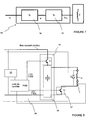
Selon un premier mode préférentiel de réalisation de l'invention tel que représenté sur les
En phase d'appel, les moyens de commande 2 comportent une unité de contrôle (Control unit) pilotant un premier interrupteur T1 placé en série avec la bobine de commande 3. L'unité de contrôle place ledit premier interrupteur en position conductrice. L'unité de contrôle (Control unit) pilote un second interrupteur T2 connecté entre la bobine de commande 3 et les moyens de régulation 50. Le second interrupteur T2 est placé en position ouverte. Le courant dans la bobine de commande 3 est alors maximal. A titre d'exemple, la phase d'appel dure environ 50 ms. A titre d'exemple de réalisation les premier et second interrupteurs T1, T2 peuvent être des transistors.In the call phase, the control means 2 comprise a control unit (control unit) controlling a first switch T1 placed in series with the
En phase de maintien, l'unité de contrôle (Control unit) ouvre le premier interrupteur T1 et applique au second interrupteur T2 un signal modulé de type PWM. La phase de maintien commence après la phase d'appel. Le premier abaisseur de tension 51 (fixed supply) fournit une tension intermédiaire fixe qui est appliquée alors à travers le second interrupteur T2 et la diode D1 dans la bobine de commande 3. La modulation de la commande de type PWM appliquée au second interrupteur T2 permet de faire varier la valeur moyenne du courant dans la bobine de commande 3.In the holding phase, the control unit (Control unit) opens the first switch T1 and applies to the second switch T2 PWM modulated signal. The maintenance phase begins after the call phase. The first voltage down regulator 51 (fixed supply) provides a fixed intermediate voltage which is then applied through the second switch T2 and the diode D1 in the
La diode D1 permet d'utiliser un second interrupteur T2 à faible tension et de le protéger de la tension d'appel U fournie par le premier interrupteur T1 pendant la phase d'appel.The diode D1 makes it possible to use a second low-voltage switch T2 and to protect it from the call voltage U supplied by the first switch T1 during the calling phase.
L'amplitude du courant de maintien d'un contacteur peut fortement varier en fonction de différents paramètres et notamment de l'état d'usure du contacteur. Le courant de maintien dans la bobine de commande 3 peut varier d'un facteur 1 à 4. A titre d'exemple d'application, le courant de maintien varie entre 20mA et 80mA alors que le courant d'appel maximal est de l'ordre de 2A.The amplitude of the holding current of a contactor can vary greatly depending on various parameters and in particular the state of wear of the contactor. The holding current in the
Selon un exemple d'application du premier mode de réalisation, le premier abaisseur de tension 51 fixe une première valeur de courant intermédiaire égale à 100mA, soit 5% de 2A. Le second abaisseur de tension 52 fixe le courant de maintien à une première valeur initiale égale à 80mA (80%). Une variation du courant de maintien de plus ou moins 1% correspond à une variation de plus ou moins 1 mA. Autrement dit, compte tenu de la valeur du pas de réglage (1%), le courant de maintien peut prendre notamment les valeurs suivantes 79mA (80mA - 1 mA) ou 81 (80mA +1 mA). Ainsi, le pas de réglage de 1 % ramené à une valeur du courant de maintien égal à 80mA, fixe le niveau de précision de réglage dudit courant de maintien à ±1,25% de la valeur initiale fixée. Selon un second exemple d'application, le courant de maintien peut être réglé sur une seconde valeur initiale égale à 20mA (cas d'un contacteur usé). Une variation du courant de maintien de plus ou moins 1% correspond à une variation de courant de maintien de plus ou moins 1mA. Autrement dit, compte tenu de la valeur du pas de réglage (1%), le courant de maintien peut prendre notamment les valeurs suivantes 19mA (20 mA - 1 mA) ou 21 mA (20mA +1 mA). Ainsi, le pas de réglage de 1% ramené à la valeur d'un courant de maintien égal à 20mA, fixe le niveau de précision de réglage dudit courant de maintien à ±5% de la valeur initiale fixée. Ces niveaux de précision sont supérieurs à ceux obtenus avec des moyens d'alimentations connus.According to an exemplary application of the first embodiment, the
Selon un second mode préférentiel de réalisation de l'invention tel que représenté sur les
En phase d'appel, les moyens de commande 2 comportent une unité de contrôle (Control unit) pilotant un premier interrupteur T1 de telle sorte qu'il soit en position conductrice. L'unité de contrôle place un second interrupteur T2 en position ouverte. Le courant dans la bobine de commande 3 est alors maximal. A titre d'exemple, la phase d'appel dure environ 50 ms. A titre d'exemple de réalisation, les premier et second interrupteurs T1, T2 peuvent être des transistors.In the call phase, the control means 2 comprise a control unit (control unit) driving a first switch T1 so that it is in the conductive position. The control unit places a second switch T2 in the open position. The current in the
En phase de maintien, l'unité de contrôle (Control unit) commande l'ouverture du premier interrupteur T1 et applique au second interrupteur T2 un signal modulé de type PWM. La phase de maintien commence après la phase d'appel. Grâce à la commande de type PWM appliquée au second interrupteur T2, la tension d'appel U, de préférence égale à celle du bus fixe (Direct Current Bus), est modulée. Le second abaisseur de tension 55 comporte un diviseur de tension (fixed divisor) qui réduit la tension modulée pour fournir une tension de maintien %u à la bobine de commande 3. La tension de maintien est appliquée à la bobine de commande 3 à travers la diode D1. La modulation de la commande de PWM appliquée au second interrupteur T2 permet de faire varier la valeur moyenne du courant dans la bobine de commande 3.In the holding phase, the control unit controls the opening of the first switch T1 and applies to the second switch T2 a PWM modulated signal. The maintenance phase begins after the call phase. Thanks to the PWM type control applied to the second switch T2, the call voltage U, preferably equal to that of the fixed bus (Direct Current Bus), is modulated. The second voltage step-down 55 has a fixed divisor which reduces the modulated voltage to provide a hold voltage% u to the
La diode D1 permet de protéger la sortie du réducteur de tension fixe (fixed divisor) de la tension d'appel fournie par l'interrupteur T1 pendant la phase d'appel.The diode D1 makes it possible to protect the fixed divisor output from the call voltage supplied by the switch T1 during the call phase.
Selon un exemple d'application du second mode de réalisation, le premier abaisseur de tension 54 variable fournit une première valeur de courant intermédiaire égale à 1,6A, soit 80% de 2A. Le second abaisseur de tension 55 fixe le courant de maintien à une première valeur initiale égale à 80mA (5%). Une variation du courant de maintien de plus ou moins 1% correspond à une variation de plus ou moins 1 mA. Autrement dit, compte tenu de la valeur du pas de réglage (1%), le courant de maintien peut prendre notamment les valeurs suivantes 79mA (80mA - 1 mA) ou 81 (80mA +1 mA). Ainsi, le pas de réglage de 1 % ramené à une valeur du courant de maintien égal à 80mA, fixe le niveau de précision de réglage dudit courant de maintien à ±1,25% de la valeur initiale fixée. Selon un second exemple d'application, le premier abaisseur de tension 54 variable fournit une première valeur de courant intermédiaire égale à 0,4A, soit 20% de 2A. Le second abaisseur de tension 55 fixe le courant de maintien à une seconde valeur initiale égale à 20mA (cas d'un contacteur usé). Une variation du courant de maintien de plus ou moins 1% correspond à une variation de courant de maintien de plus ou moins 1mA. Autrement dit, compte tenu de la valeur du pas de réglage (1%), le courant de maintien peut prendre notamment les valeurs suivantes 19mA (20 mA - 1 mA) ou 21 mA (20mA +1 mA). Ainsi, le pas de réglage de 1% ramené à la valeur d'un courant de maintien égal à 20mA, fixe le niveau de précision de réglage dudit courant de maintien à ±5% de la valeur initiale fixée. Ces niveaux de précision sont supérieurs à ceux obtenus avec des moyens d'alimentations connus.According to an exemplary application of the second embodiment, the first
Selon un troisième mode préférentiel de réalisation de l'invention tel que représenté sur les
En phase d'appel, les moyens de commande 2 comportent une unité de contrôle (Control unit) pilotant les premier et second interrupteurs T1 et T2 de telle sorte qu'ils soient toujours en position conductrice. Le courant d'appel dans la bobine de commande 3 est alors maximal. A titre d'exemple, la phase d'appel dure environ 50 ms.In the call phase, the control means 2 comprise a control unit (control unit) controlling the first and second switches T1 and T2 so that they are always in the conductive position. The inrush current in the
En phase de maintien, l'unité de contrôle (Control unit) applique une modulation d'impulsion de type PWM différente à chacun des interrupteurs T1 et T2. La phase de maintien commence après la phase d'appel.In the hold phase, the control unit applies a different PWM pulse modulation to each of the switches T1 and T2. The maintenance phase begins after the call phase.
Le premier abaisseur de tension 56 est piloté par l'unité de contrôle. La tension appliquée par l'interrupteur T1 à partir du bus fixe (Direct Current Bus) en entrée du moyen de lissage est de type PWM. Le moyen de lissage 58 le transforme en une tension équivalente continue. Cette tension équivalente continue est ensuite modulée par le second abaisseur de tension par l'application d'une commande PWM sur l'interrupteur T2. Cette tension modulée permet de faire varier la valeur moyenne du courant dans la bobine de commande 3.The first voltage step-down 56 is controlled by the control unit. The voltage applied by the switch T1 from the fixed bus (Direct Current Bus) at the input of the smoothing means is of the PWM type. The smoothing means 58 transforms it into a continuous equivalent voltage. This continuous equivalent voltage is then modulated by the second voltage step by the application of a PWM command on the switch T2. This modulated voltage makes it possible to vary the value average of the current in the
Selon un premier exemple d'application du troisième mode de réalisation, le premier abaisseur de tension fixe une première valeur de courant intermédiaire égale à 100mA, soit 5% de 2A. Le second abaisseur de tension fixe le courant de maintien à une première valeur initiale égale à 80mA (80%). Une variation du courant de maintien de plus ou moins 1% correspond à une variation de plus ou moins 1mA. Autrement dit, compte tenu de la valeur du pas de réglage égale à 1%, le courant de maintien peut prendre notamment les valeurs suivantes 79mA (80mA - 1 mA) ou 81 (80mA +1 mA). Ainsi, le pas de réglage de 1% ramené à une valeur du courant de maintien égal à 80mA, fixe le niveau de précision de réglage dudit courant de maintien à ±1,25% de la valeur initiale fixée.According to a first example of application of the third embodiment, the first voltage step set a first intermediate current value equal to 100mA, ie 5% of 2A. The second voltage buckener sets the holding current to a first initial value of 80mA (80%). A variation of the holding current of plus or minus 1% corresponds to a variation of plus or minus 1mA. In other words, given the value of the setting step equal to 1%, the holding current can take in particular the following values 79mA (80mA - 1 mA) or 81 (80mA +1 mA). Thus, the setting step of 1% reduced to a value of the holding current equal to 80 mA, sets the accuracy level of adjustment of said holding current to ± 1.25% of the fixed initial value.
En outre, selon un second exemple d'application, le courant de maintien peut être réglé sur une seconde valeur initiale égale à 20mA (cas d'un contacteur usé). Selon cet exemple, le premier abaisseur de tension fixe alors une première valeur de courant intermédiaire égale à 40mA (2% de 2A) et le second abaisseur de tension fixe une seconde valeur initiale de courant de maintien égale à 20mA (50%). Une variation du courant de maintien de plus ou moins 1% correspond à une variation de plus ou moins 0,4mA. Autrement dit, compte tenu de la valeur du pas de réglage égale à 1 %, le courant de maintien peut prendre notamment les valeurs suivantes 19,6mA (20 mA - 0,4mA) ou 20,4mA (20mA +0,4mA). Ainsi, le pas de réglage de 1% ramené à la valeur d'un courant de maintien égal à 20mA, fixe le niveau de précision de réglage dudit courant de maintien à ±2% de la valeur initiale fixée.In addition, according to a second example of application, the holding current can be set to a second initial value equal to 20 mA (in the case of a worn contactor). According to this example, the first voltage step then sets a first intermediate current value equal to 40mA (2% of 2A) and the second voltage step-down secures a second initial holding current value equal to 20mA (50%). A variation of the holding current of plus or minus 1% corresponds to a variation of plus or minus 0.4mA. In other words, given the value of the setting step equal to 1%, the holding current can take in particular the following values 19.6mA (20 mA - 0.4mA) or 20.4mA (20mA + 0.4mA). Thus, the setting step of 1% reduced to the value of a holding current equal to 20 mA, sets the precision level of adjustment of said holding current to ± 2% of the initial value fixed.
Ces niveaux de précision sont supérieurs à ceux obtenus avec des moyens d'alimentations connus.These levels of precision are higher than those obtained with known feed means.
Selon le niveau d'usure des contacts fixes et mobiles, les ressorts de pôle 5 seront plus ou moins comprimés et l'effort fourni par l'actionneur 1 sera plus ou moins important. En effet, moins les contacts 20, 21 sont usés, plus les ressorts de pôle 5 sont comprimés et donc plus l'effort fourni par l'actionneur 1 pour comprimer ces ressorts doit être important. Par conséquent, il est possible de corréler le niveau d'usure des contacts avec l'effort fourni par l'actionneur pour comprimer les ressorts de pôle 5. La
Selon l'invention, le courant de commande qui est injecté dans la bobine de commande 3 lorsque l'armature mobile 11 se sépare de la culasse fixe 10 est donc représentatif de l'effort minimal fourni par l'actionneur 1 pour maintenir l'armature mobile 11 en position fermée et lutter contre les ressorts de pôle 5. Le courant de commande mesuré à ce moment précis peut donc être traité pour détecter l'usure des contacts ou pour optimiser le fonctionnement de l'appareil.According to the invention, the control current which is injected into the
Un moyen de mesure du courant 7 peut être ajouté aux différents modes préférentiels de réalisation afin de permettre une régulation en boucle fermé plus précise des courants traversant la bobine de commande 3. Les moyens de commande 2 comportent des moyens de mesure 7 du courant de commande i1 dans la bobine de commande 3. Comme décrits dans la demande de brevet de la demanderesse ayant pour titre « Appareil électrique interrupteur à fonctionnement optimisé », les moyens de commande 2 comportent des moyens de détermination d'un niveau d'usure des contacts fixes et mobiles à partir du courant de commande i1 lors de la séparation de l'armature mobile 11 par rapport à la culasse fixe 10. Pour déterminer le niveau d'usure des contacts, le courant i1 qui est mesuré par les moyens de mesure 7 pourra par exemple être comparé par les moyens de commande 2 à différents seuils prédéterminés enregistrés dans l'appareil pour en déduire un niveau d'usure des contacts ou comparé au courant mesuré lors de l'opération précédente afin de suivre son évolution. Il est également possible de convertir le courant mesuré i1 en pourcentage d'usure et de comparer ce pourcentage avec différents seuils. D'autres modes de traitement peuvent bien entendu être envisagés.Current measuring means 7 may be added to the various preferred embodiments to allow more precise closed-loop regulation of the currents flowing through the
Selon l'invention, grâce à la mesure du courant par les moyens de mesure 7 lors de la séparation de l'armature mobile 11 par rapport à la culasse fixe 10, les moyens de commande 2 peuvent également déterminer un courant de commande optimal de maintien à appliquer à l'actionneur 1. Habituellement, le courant de maintien appliqué à l'actionneur 1 est choisi suffisamment important pour que l'armature mobile 11 puisse rester en position fermée quel que soit le nombre d'additifs optionnels ajouté sur l'appareil, l'intensité des chocs ou vibrations subis par l'appareil ou l'usure de l'appareil. Ce courant est donc très souvent choisi plus important que nécessaire pour pouvoir tenir compte de ces différentes situations.According to the invention, by measuring the current by the measuring means 7 during the separation of the moving
Le courant mesuré i1 lors de la séparation de l'armature mobile 11 par rapport à la culasse fixe 10 peut donc être traité pour réajuster le courant de maintien et déterminer un courant de maintien optimal qui soit adapté à l'environnement et à la configuration de l'appareil. Le courant mesuré lors de la séparation de l'armature mobile 11 est par exemple augmenté d'un pourcentage déterminé permettant de s'assurer qu'il est suffisant pour le maintien de l'armature mobile 11 en position fermée dans son environnement et dans sa configuration. La détermination du courant de maintien optimal pourra être effectuée à intervalles réguliers pour tenir compte d'éventuels ajouts d'additifs ou de changement d'environnement. Cette fonctionnalité peut être prévue seule dans l'appareil électrique ou mise en oeuvre en complément de la détection d'usure des contacts. Elle permet notamment d'optimiser la consommation d'énergie de l'appareil en injectant un courant de commande juste nécessaire pour le maintien de l'armature mobile 11 en position de fermeture.The current measured i1 during the separation of the moving
Les moyens de régulation 50 selon les modes de réalisation de l'invention sont aptes à commander avec précision une tension de maintien %u fournie à la bobine de commande 3.The regulation means 50 according to the embodiments of the invention are able to precisely control a holding voltage% u supplied to the
Ladite demande de brevet de la demanderesse ayant pour titre « Appareil électrique interrupteur à fonctionnement optimisé » décrit en outre un procédé de commande comportant les étapes suivantes de :
- détection de la séparation de l'armature mobile 11 par rapport à la culasse fixe 10,
- mesure du courant de commande i(t) traversant la bobine de commande 3 lors de la séparation de l'armature mobile 11 par rapport à la culasse fixe 10,
- traitement du courant de commande mesuré i1 en vue de commander l'appareil ou d'effectuer un diagnostic de l'appareil.
- detecting the separation of the moving
armature 11 with respect to the fixedyoke 10, - measuring the control current i (t) passing through the
control coil 3 during the separation of themobile armature 11 with respect to the fixedyoke 10, - processing of the measured control current i1 in order to control the apparatus or to make a diagnosis of the apparatus.
L'actionneur selon les modes de réalisation de l'invention est particulièrement efficace en terme de réduction des perturbations électromagnétique de type CEM.The actuator according to the embodiments of the invention is particularly effective in terms of reducing electromagnetic disturbances of the EMC type.
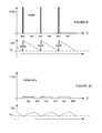
De préférence, l'utilisation de moyen de commande apte à moduler la tension appliquée à la bobine de commande 3 selon une modulation d'impulsion en largeur de type PWM tend à générer des perturbations de type CEM. Comme représenté sur la
Pendant la phase de maintien, le réglage de la modulation de type PWM est obligatoirement faible afin de générer un courant faible dans la bobine de commande 3. La tension appliquée à la bobine peut s'exprimer avec la formule suivante : 
Avec L l'inductance de la bobine de commande 3, U la tension appliquée aux bornes de ladite bobine, R la résistance de ladite bobineWith L the inductance of the
Ainsi, la variation instantanée du courant électrique pendant des temps très courts (di/dt) peut s'exprimer avec la formule suivante : 
Pendant la phase de maintien, la valeur du produit de la résistance par le courant RI est très faible comparé à la tension U appliquée à la bobine de commande 3. En effet, à titre d'exemple d'application, si la tension d'appel est égale à 340 Volts (U = 340V) et si le réglage de la modulation de type PWM est égal à 2%, le produit de résistance par le courant RI est égal à 6,8 Volts (RI = 2% x U).During the holding phase, the value of the product of the resistance by the current RI is very small compared to the voltage U applied to the
Dans une application de type connue, le terme RI est alors négligeable devant celui de U et le rapport di/dt peut s'exprimer avec la formule suivante : 
Soit, à titre d'exemple : 
Dans une application selon un mode de réalisation de l'invention tel que représenté sur la 
soit 
soit 
is
is
En conclusion, pour une même bobine de commande 3, en comparant les rapports di/dt obtenus dans une application connue et dans une application selon un des modes de réalisation de l'invention, on observe une très forte réduction, notamment une réduction de l'émission CEM d'une valeur égale à 65 (340 / 5,2 = 65).In conclusion, for the
Claims (10)
l'actionneur en position fermée;
the actuator in the closed position;
Priority Applications (1)
| Application Number | Priority Date | Filing Date | Title |
|---|---|---|---|
| PL10354055T PL2320438T3 (en) | 2009-11-06 | 2010-09-30 | Electromagnetic actuator and electrical contactor comprising such actuator |
Applications Claiming Priority (1)
| Application Number | Priority Date | Filing Date | Title |
|---|---|---|---|
| FR0905335A FR2952469A1 (en) | 2009-11-06 | 2009-11-06 | ELECTROMAGNETIC ACTUATOR AND ELECTRICAL CONTACTOR COMPRISING SUCH ACTUATOR. |
Publications (2)
| Publication Number | Publication Date |
|---|---|
| EP2320438A1 true EP2320438A1 (en) | 2011-05-11 |
| EP2320438B1 EP2320438B1 (en) | 2012-05-23 |
Family
ID=42138930
Family Applications (1)
| Application Number | Title | Priority Date | Filing Date |
|---|---|---|---|
| EP10354055A Not-in-force EP2320438B1 (en) | 2009-11-06 | 2010-09-30 | Electromagnetic actuator and electrical contactor comprising such actuator |
Country Status (5)
| Country | Link |
|---|---|
| EP (1) | EP2320438B1 (en) |
| CN (1) | CN102054627B (en) |
| ES (1) | ES2384782T3 (en) |
| FR (1) | FR2952469A1 (en) |
| PL (1) | PL2320438T3 (en) |
Cited By (1)
| Publication number | Priority date | Publication date | Assignee | Title |
|---|---|---|---|---|
| US9786457B2 (en) | 2015-01-14 | 2017-10-10 | General Electric Company | Systems and methods for freewheel contactor circuits |
Families Citing this family (2)
| Publication number | Priority date | Publication date | Assignee | Title |
|---|---|---|---|---|
| FR2983629B1 (en) * | 2011-12-02 | 2013-11-22 | Schneider Electric Ind Sas | METHOD FOR EVALUATING THE TEMPERATURE OF AN ELECTROMAGNETIC CONTACTOR AND CONTACTOR FOR CARRYING OUT SAID METHOD |
| DE102012218988A1 (en) * | 2012-10-18 | 2014-04-24 | Robert Bosch Gmbh | Control circuit for at least one contactor and a method for operating at least one contactor |
Citations (6)
| Publication number | Priority date | Publication date | Assignee | Title |
|---|---|---|---|---|
| US3660730A (en) * | 1970-12-16 | 1972-05-02 | Design Elements Inc | Solenoid drive circuit |
| FR2568715A1 (en) * | 1984-08-03 | 1986-02-07 | Telemecanique Electrique | DEVICE FOR CONTROLLING AN ELECTROMAGNET COIL AND ELECTRIC SWITCHING APPARATUS PROVIDED WITH SUCH A DEVICE |
| US5422780A (en) * | 1992-12-22 | 1995-06-06 | The Lee Company | Solenoid drive circuit |
| DE19719602A1 (en) * | 1997-05-09 | 1998-11-12 | Fahrzeugklimaregelung Gmbh | Electronic control circuit |
| EP1009003A1 (en) * | 1998-12-07 | 2000-06-14 | Schneider Electric Industries SA | Control device for an electromagnet, with a power supply powered by the holding current of the electromagnet |
| EP2019396A1 (en) * | 2007-07-23 | 2009-01-28 | Schneider Electric Industries SAS | Electromagnetic actuator with at least two coils |
Family Cites Families (2)
| Publication number | Priority date | Publication date | Assignee | Title |
|---|---|---|---|---|
| CN2052932U (en) * | 1989-09-05 | 1990-02-14 | 张凡 | Magnet holding traction electromagnet and controlled circuit thereof |
| CN101546644A (en) * | 2008-03-26 | 2009-09-30 | 杨泰和 | Drive circuit for full-voltage starting and reduced-voltage maintenance of electric excitation loads |
-
2009
- 2009-11-06 FR FR0905335A patent/FR2952469A1/en active Pending
-
2010
- 2010-09-30 ES ES10354055T patent/ES2384782T3/en active Active
- 2010-09-30 PL PL10354055T patent/PL2320438T3/en unknown
- 2010-09-30 EP EP10354055A patent/EP2320438B1/en not_active Not-in-force
- 2010-11-08 CN CN201010543553.3A patent/CN102054627B/en not_active Expired - Fee Related
Patent Citations (6)
| Publication number | Priority date | Publication date | Assignee | Title |
|---|---|---|---|---|
| US3660730A (en) * | 1970-12-16 | 1972-05-02 | Design Elements Inc | Solenoid drive circuit |
| FR2568715A1 (en) * | 1984-08-03 | 1986-02-07 | Telemecanique Electrique | DEVICE FOR CONTROLLING AN ELECTROMAGNET COIL AND ELECTRIC SWITCHING APPARATUS PROVIDED WITH SUCH A DEVICE |
| US5422780A (en) * | 1992-12-22 | 1995-06-06 | The Lee Company | Solenoid drive circuit |
| DE19719602A1 (en) * | 1997-05-09 | 1998-11-12 | Fahrzeugklimaregelung Gmbh | Electronic control circuit |
| EP1009003A1 (en) * | 1998-12-07 | 2000-06-14 | Schneider Electric Industries SA | Control device for an electromagnet, with a power supply powered by the holding current of the electromagnet |
| EP2019396A1 (en) * | 2007-07-23 | 2009-01-28 | Schneider Electric Industries SAS | Electromagnetic actuator with at least two coils |
Cited By (1)
| Publication number | Priority date | Publication date | Assignee | Title |
|---|---|---|---|---|
| US9786457B2 (en) | 2015-01-14 | 2017-10-10 | General Electric Company | Systems and methods for freewheel contactor circuits |
Also Published As
| Publication number | Publication date |
|---|---|
| CN102054627B (en) | 2015-02-11 |
| ES2384782T3 (en) | 2012-07-12 |
| EP2320438B1 (en) | 2012-05-23 |
| PL2320438T3 (en) | 2012-10-31 |
| FR2952469A1 (en) | 2011-05-13 |
| CN102054627A (en) | 2011-05-11 |
Similar Documents
| Publication | Publication Date | Title |
|---|---|---|
| EP3105845B1 (en) | Dc voltage supply system configured to precharge a smoothing capacitor before supplying a load | |
| EP1009006B1 (en) | Standard control device for an electromagnet for opening or closing a circuit breaker | |
| EP2794342B1 (en) | Method for monitoring and optimising the operation of a charging terminal for an electric vehicle and charging terminal for implementing said method | |
| EP2320438B1 (en) | Electromagnetic actuator and electrical contactor comprising such actuator | |
| FR2568715A1 (en) | DEVICE FOR CONTROLLING AN ELECTROMAGNET COIL AND ELECTRIC SWITCHING APPARATUS PROVIDED WITH SUCH A DEVICE | |
| EP3288059B1 (en) | Commandable trip unit for an electrical circuit breaker | |
| EP2466607A1 (en) | Electromagnetic actuator with at least two coils | |
| EP3087647B1 (en) | Power controller with linear control of current peak limitation and with short-circuit protection | |
| FR2891094A1 (en) | Battery charging method, involves tracking maximum power point of source by indirectly measuring consumed power and modulating duty factor of input stage based on measurement of consumed power | |
| FR2786915A1 (en) | DEVICE FOR CONTROLLING AN ELECTROMAGNET, WITH DETECTION OF AN UNSUITABLE MOVEMENT OF THE MOBILE CORE OF THE ELECTROMAGNET | |
| EP2503575A1 (en) | Method and device for diagnosing an actuator and actuator comprising such a device | |
| CA2342716C (en) | Electrical circuit for transmitting condition information, namely from a unit of railway rolling stock, and electrical system containing the aforesaid circuit | |
| WO2014167089A1 (en) | Electrical contactor and method for controlling an electromagnetic coil in such a contactor | |
| EP3291271B1 (en) | Control method for an actuating device, related actuating device and switching device | |
| EP0720193A1 (en) | Electric control for opening and closing a switch or a circuit breaker | |
| EP3381100B1 (en) | Method and device for switching on a power transformer | |
| EP4036950B1 (en) | Electromagnetic actuator and method of controlling an electromagnetic actuator | |
| EP2458720B1 (en) | Power converter with a controlled current source and connected in single-phase mode | |
| FR3004030A1 (en) | MOTOR CONTROL DEVICE AND POWER ASSISTED STEERING APPARATUS COMPRISING THE ENGINE CONTROLLER | |
| FR2803956A1 (en) | Supply of actuating winding on power contactor, uses control of DC -DC converter connected between DC supply and coil to regulate current in coil | |
| WO2004051686A1 (en) | Electromagnetic relay control | |
| EP3391521B1 (en) | Improved recharging device for recharging electrical equipment, in particular an electric vehicle | |
| FR2704699A1 (en) | Method and device for producing a high voltage, especially for electrostatic application of a coating product | |
| EP2696501A1 (en) | Method for controlling an electromagnetic contactor and electromagnetic contactor implementing such a method | |
| WO2010084253A1 (en) | Method and device for the high energy yield charge-test of an equipment |
Legal Events
| Date | Code | Title | Description |
|---|---|---|---|
| PUAI | Public reference made under article 153(3) epc to a published international application that has entered the european phase |
Free format text: ORIGINAL CODE: 0009012 |
|
| AK | Designated contracting states |
Kind code of ref document: A1 Designated state(s): AL AT BE BG CH CY CZ DE DK EE ES FI FR GB GR HR HU IE IS IT LI LT LU LV MC MK MT NL NO PL PT RO SE SI SK SM TR |
|
| AX | Request for extension of the european patent |
Extension state: BA ME RS |
|
| 17P | Request for examination filed |
Effective date: 20111026 |
|
| GRAP | Despatch of communication of intention to grant a patent |
Free format text: ORIGINAL CODE: EPIDOSNIGR1 |
|
| GRAS | Grant fee paid |
Free format text: ORIGINAL CODE: EPIDOSNIGR3 |
|
| GRAA | (expected) grant |
Free format text: ORIGINAL CODE: 0009210 |
|
| AK | Designated contracting states |
Kind code of ref document: B1 Designated state(s): AL AT BE BG CH CY CZ DE DK EE ES FI FR GB GR HR HU IE IS IT LI LT LU LV MC MK MT NL NO PL PT RO SE SI SK SM TR |
|
| REG | Reference to a national code |
Ref country code: GB Ref legal event code: FG4D Free format text: NOT ENGLISH |
|
| REG | Reference to a national code |
Ref country code: CH Ref legal event code: EP |
|
| REG | Reference to a national code |
Ref country code: AT Ref legal event code: REF Ref document number: 559408 Country of ref document: AT Kind code of ref document: T Effective date: 20120615 |
|
| REG | Reference to a national code |
Ref country code: IE Ref legal event code: FG4D Free format text: LANGUAGE OF EP DOCUMENT: FRENCH |
|
| REG | Reference to a national code |
Ref country code: ES Ref legal event code: FG2A Ref document number: 2384782 Country of ref document: ES Kind code of ref document: T3 Effective date: 20120712 |
|
| REG | Reference to a national code |
Ref country code: DE Ref legal event code: R096 Ref document number: 602010001703 Country of ref document: DE Effective date: 20120719 |
|
| REG | Reference to a national code |
Ref country code: SE Ref legal event code: TRGR |
|
| REG | Reference to a national code |
Ref country code: NL Ref legal event code: VDEP Effective date: 20120523 |
|
| REG | Reference to a national code |
Ref country code: LT Ref legal event code: MG4D Effective date: 20120523 |
|
| PG25 | Lapsed in a contracting state [announced via postgrant information from national office to epo] |
Ref country code: FI Free format text: LAPSE BECAUSE OF FAILURE TO SUBMIT A TRANSLATION OF THE DESCRIPTION OR TO PAY THE FEE WITHIN THE PRESCRIBED TIME-LIMIT Effective date: 20120523 Ref country code: LT Free format text: LAPSE BECAUSE OF FAILURE TO SUBMIT A TRANSLATION OF THE DESCRIPTION OR TO PAY THE FEE WITHIN THE PRESCRIBED TIME-LIMIT Effective date: 20120523 Ref country code: CY Free format text: LAPSE BECAUSE OF FAILURE TO SUBMIT A TRANSLATION OF THE DESCRIPTION OR TO PAY THE FEE WITHIN THE PRESCRIBED TIME-LIMIT Effective date: 20120523 Ref country code: NO Free format text: LAPSE BECAUSE OF FAILURE TO SUBMIT A TRANSLATION OF THE DESCRIPTION OR TO PAY THE FEE WITHIN THE PRESCRIBED TIME-LIMIT Effective date: 20120823 Ref country code: IS Free format text: LAPSE BECAUSE OF FAILURE TO SUBMIT A TRANSLATION OF THE DESCRIPTION OR TO PAY THE FEE WITHIN THE PRESCRIBED TIME-LIMIT Effective date: 20120923 |
|
| REG | Reference to a national code |
Ref country code: PL Ref legal event code: T3 |
|
| REG | Reference to a national code |
Ref country code: AT Ref legal event code: MK05 Ref document number: 559408 Country of ref document: AT Kind code of ref document: T Effective date: 20120523 |
|
| PG25 | Lapsed in a contracting state [announced via postgrant information from national office to epo] |
Ref country code: GR Free format text: LAPSE BECAUSE OF FAILURE TO SUBMIT A TRANSLATION OF THE DESCRIPTION OR TO PAY THE FEE WITHIN THE PRESCRIBED TIME-LIMIT Effective date: 20120824 Ref country code: PT Free format text: LAPSE BECAUSE OF FAILURE TO SUBMIT A TRANSLATION OF THE DESCRIPTION OR TO PAY THE FEE WITHIN THE PRESCRIBED TIME-LIMIT Effective date: 20120924 Ref country code: SI Free format text: LAPSE BECAUSE OF FAILURE TO SUBMIT A TRANSLATION OF THE DESCRIPTION OR TO PAY THE FEE WITHIN THE PRESCRIBED TIME-LIMIT Effective date: 20120523 Ref country code: HR Free format text: LAPSE BECAUSE OF FAILURE TO SUBMIT A TRANSLATION OF THE DESCRIPTION OR TO PAY THE FEE WITHIN THE PRESCRIBED TIME-LIMIT Effective date: 20120523 Ref country code: LV Free format text: LAPSE BECAUSE OF FAILURE TO SUBMIT A TRANSLATION OF THE DESCRIPTION OR TO PAY THE FEE WITHIN THE PRESCRIBED TIME-LIMIT Effective date: 20120523 |
|
| PG25 | Lapsed in a contracting state [announced via postgrant information from national office to epo] |
Ref country code: NL Free format text: LAPSE BECAUSE OF FAILURE TO SUBMIT A TRANSLATION OF THE DESCRIPTION OR TO PAY THE FEE WITHIN THE PRESCRIBED TIME-LIMIT Effective date: 20120523 Ref country code: AT Free format text: LAPSE BECAUSE OF FAILURE TO SUBMIT A TRANSLATION OF THE DESCRIPTION OR TO PAY THE FEE WITHIN THE PRESCRIBED TIME-LIMIT Effective date: 20120523 Ref country code: RO Free format text: LAPSE BECAUSE OF FAILURE TO SUBMIT A TRANSLATION OF THE DESCRIPTION OR TO PAY THE FEE WITHIN THE PRESCRIBED TIME-LIMIT Effective date: 20120523 Ref country code: DK Free format text: LAPSE BECAUSE OF FAILURE TO SUBMIT A TRANSLATION OF THE DESCRIPTION OR TO PAY THE FEE WITHIN THE PRESCRIBED TIME-LIMIT Effective date: 20120523 Ref country code: EE Free format text: LAPSE BECAUSE OF FAILURE TO SUBMIT A TRANSLATION OF THE DESCRIPTION OR TO PAY THE FEE WITHIN THE PRESCRIBED TIME-LIMIT Effective date: 20120523 Ref country code: SK Free format text: LAPSE BECAUSE OF FAILURE TO SUBMIT A TRANSLATION OF THE DESCRIPTION OR TO PAY THE FEE WITHIN THE PRESCRIBED TIME-LIMIT Effective date: 20120523 Ref country code: CZ Free format text: LAPSE BECAUSE OF FAILURE TO SUBMIT A TRANSLATION OF THE DESCRIPTION OR TO PAY THE FEE WITHIN THE PRESCRIBED TIME-LIMIT Effective date: 20120523 |
|
| PLBE | No opposition filed within time limit |
Free format text: ORIGINAL CODE: 0009261 |
|
| STAA | Information on the status of an ep patent application or granted ep patent |
Free format text: STATUS: NO OPPOSITION FILED WITHIN TIME LIMIT |
|
| BERE | Be: lapsed |
Owner name: SCHNEIDER ELECTRIC INDUSTRIES SAS Effective date: 20120930 |
|
| PG25 | Lapsed in a contracting state [announced via postgrant information from national office to epo] |
Ref country code: MC Free format text: LAPSE BECAUSE OF NON-PAYMENT OF DUE FEES Effective date: 20120930 |
|
| 26N | No opposition filed |
Effective date: 20130226 |
|
| REG | Reference to a national code |
Ref country code: DE Ref legal event code: R097 Ref document number: 602010001703 Country of ref document: DE Effective date: 20130226 |
|
| REG | Reference to a national code |
Ref country code: IE Ref legal event code: MM4A |
|
| PG25 | Lapsed in a contracting state [announced via postgrant information from national office to epo] |
Ref country code: IE Free format text: LAPSE BECAUSE OF NON-PAYMENT OF DUE FEES Effective date: 20120930 Ref country code: BE Free format text: LAPSE BECAUSE OF NON-PAYMENT OF DUE FEES Effective date: 20120930 Ref country code: BG Free format text: LAPSE BECAUSE OF FAILURE TO SUBMIT A TRANSLATION OF THE DESCRIPTION OR TO PAY THE FEE WITHIN THE PRESCRIBED TIME-LIMIT Effective date: 20120823 |
|
| PG25 | Lapsed in a contracting state [announced via postgrant information from national office to epo] |
Ref country code: MT Free format text: LAPSE BECAUSE OF FAILURE TO SUBMIT A TRANSLATION OF THE DESCRIPTION OR TO PAY THE FEE WITHIN THE PRESCRIBED TIME-LIMIT Effective date: 20120523 Ref country code: AL Free format text: LAPSE BECAUSE OF FAILURE TO SUBMIT A TRANSLATION OF THE DESCRIPTION OR TO PAY THE FEE WITHIN THE PRESCRIBED TIME-LIMIT Effective date: 20120523 |
|
| PG25 | Lapsed in a contracting state [announced via postgrant information from national office to epo] |
Ref country code: TR Free format text: LAPSE BECAUSE OF FAILURE TO SUBMIT A TRANSLATION OF THE DESCRIPTION OR TO PAY THE FEE WITHIN THE PRESCRIBED TIME-LIMIT Effective date: 20120523 |
|
| PG25 | Lapsed in a contracting state [announced via postgrant information from national office to epo] |
Ref country code: LU Free format text: LAPSE BECAUSE OF NON-PAYMENT OF DUE FEES Effective date: 20120930 Ref country code: SM Free format text: LAPSE BECAUSE OF FAILURE TO SUBMIT A TRANSLATION OF THE DESCRIPTION OR TO PAY THE FEE WITHIN THE PRESCRIBED TIME-LIMIT Effective date: 20120523 |
|
| PG25 | Lapsed in a contracting state [announced via postgrant information from national office to epo] |
Ref country code: HU Free format text: LAPSE BECAUSE OF FAILURE TO SUBMIT A TRANSLATION OF THE DESCRIPTION OR TO PAY THE FEE WITHIN THE PRESCRIBED TIME-LIMIT Effective date: 20100930 |
|
| REG | Reference to a national code |
Ref country code: CH Ref legal event code: PL |
|
| PG25 | Lapsed in a contracting state [announced via postgrant information from national office to epo] |
Ref country code: CH Free format text: LAPSE BECAUSE OF NON-PAYMENT OF DUE FEES Effective date: 20140930 Ref country code: LI Free format text: LAPSE BECAUSE OF NON-PAYMENT OF DUE FEES Effective date: 20140930 Ref country code: MK Free format text: LAPSE BECAUSE OF FAILURE TO SUBMIT A TRANSLATION OF THE DESCRIPTION OR TO PAY THE FEE WITHIN THE PRESCRIBED TIME-LIMIT Effective date: 20120523 |
|
| REG | Reference to a national code |
Ref country code: FR Ref legal event code: PLFP Year of fee payment: 7 |
|
| REG | Reference to a national code |
Ref country code: FR Ref legal event code: PLFP Year of fee payment: 8 |
|
| REG | Reference to a national code |
Ref country code: FR Ref legal event code: PLFP Year of fee payment: 9 |
|
| PGFP | Annual fee paid to national office [announced via postgrant information from national office to epo] |
Ref country code: FR Payment date: 20180924 Year of fee payment: 9 Ref country code: IT Payment date: 20180919 Year of fee payment: 9 Ref country code: DE Payment date: 20180921 Year of fee payment: 9 |
|
| PGFP | Annual fee paid to national office [announced via postgrant information from national office to epo] |
Ref country code: SE Payment date: 20180910 Year of fee payment: 9 Ref country code: PL Payment date: 20180712 Year of fee payment: 9 Ref country code: GB Payment date: 20180926 Year of fee payment: 9 |
|
| PGFP | Annual fee paid to national office [announced via postgrant information from national office to epo] |
Ref country code: ES Payment date: 20181001 Year of fee payment: 9 |
|
| REG | Reference to a national code |
Ref country code: DE Ref legal event code: R119 Ref document number: 602010001703 Country of ref document: DE |
|
| PG25 | Lapsed in a contracting state [announced via postgrant information from national office to epo] |
Ref country code: DE Free format text: LAPSE BECAUSE OF NON-PAYMENT OF DUE FEES Effective date: 20200401 |
|
| PG25 | Lapsed in a contracting state [announced via postgrant information from national office to epo] |
Ref country code: IT Free format text: LAPSE BECAUSE OF NON-PAYMENT OF DUE FEES Effective date: 20190930 Ref country code: SE Free format text: LAPSE BECAUSE OF NON-PAYMENT OF DUE FEES Effective date: 20191001 |
|
| GBPC | Gb: european patent ceased through non-payment of renewal fee |
Effective date: 20190930 |
|
| PG25 | Lapsed in a contracting state [announced via postgrant information from national office to epo] |
Ref country code: GB Free format text: LAPSE BECAUSE OF NON-PAYMENT OF DUE FEES Effective date: 20190930 Ref country code: FR Free format text: LAPSE BECAUSE OF NON-PAYMENT OF DUE FEES Effective date: 20190930 |
|
| REG | Reference to a national code |
Ref country code: ES Ref legal event code: FD2A Effective date: 20210202 |
|
| PG25 | Lapsed in a contracting state [announced via postgrant information from national office to epo] |
Ref country code: ES Free format text: LAPSE BECAUSE OF NON-PAYMENT OF DUE FEES Effective date: 20191001 |
|
| PG25 | Lapsed in a contracting state [announced via postgrant information from national office to epo] |
Ref country code: PL Free format text: LAPSE BECAUSE OF NON-PAYMENT OF DUE FEES Effective date: 20190930 |