EP2320004B1 - Profilmodul zur Herstellung einer Dachkonstruktion - Google Patents
Profilmodul zur Herstellung einer Dachkonstruktion Download PDFInfo
- Publication number
- EP2320004B1 EP2320004B1 EP20090013994 EP09013994A EP2320004B1 EP 2320004 B1 EP2320004 B1 EP 2320004B1 EP 20090013994 EP20090013994 EP 20090013994 EP 09013994 A EP09013994 A EP 09013994A EP 2320004 B1 EP2320004 B1 EP 2320004B1
- Authority
- EP
- European Patent Office
- Prior art keywords
- profile
- roof construction
- sliding element
- construction according
- guiding profile
- Prior art date
- Legal status (The legal status is an assumption and is not a legal conclusion. Google has not performed a legal analysis and makes no representation as to the accuracy of the status listed.)
- Active
Links
Images
Classifications
-
- E—FIXED CONSTRUCTIONS
- E04—BUILDING
- E04D—ROOF COVERINGS; SKY-LIGHTS; GUTTERS; ROOF-WORKING TOOLS
- E04D12/00—Non-structural supports for roofing materials, e.g. battens, boards
- E04D12/004—Battens
- E04D12/006—Batten-supporting means
-
- E—FIXED CONSTRUCTIONS
- E04—BUILDING
- E04D—ROOF COVERINGS; SKY-LIGHTS; GUTTERS; ROOF-WORKING TOOLS
- E04D3/00—Roof covering by making use of flat or curved slabs or stiff sheets
- E04D3/36—Connecting; Fastening
- E04D3/3605—Connecting; Fastening of roof covering supported directly by the roof structure
- E04D3/3606—Connecting; Fastening of roof covering supported directly by the roof structure the fastening means being screws or nails
-
- E—FIXED CONSTRUCTIONS
- E04—BUILDING
- E04D—ROOF COVERINGS; SKY-LIGHTS; GUTTERS; ROOF-WORKING TOOLS
- E04D3/00—Roof covering by making use of flat or curved slabs or stiff sheets
- E04D3/36—Connecting; Fastening
- E04D3/361—Connecting; Fastening by specially-profiled marginal portions of the slabs or sheets
- E04D2003/3615—Separate fastening elements fixed to the roof structure and consisting of parts permitting relative movement to each other, e.g. for thermal expansion
Definitions
- the invention relates to a roof construction according to the preamble of patent claim 1.
- roof construction For roofing example of terraces, it is known to use profile or Sprossenkonstrutationen which record plate elements. Such a roof construction is carried out regularly using rafters which are spaced from each other, and on which spaced slats are mounted in the transverse direction. As roof battens often called profile rungs are used, on which preferably made of thermoplastic material plate elements are attached. Roof structures of the aforementioned type are for example from the FR 1.452.957 or the US 6,082,070 known, in US 6,082,070 a roof construction according to the preamble of claim 1 is disclosed.
- thermoplastic elements made of thermoplastic material deform under heat, which can lead to disturbing noise developments. These noise developments are due in particular to relative movements between the battens or profiles and Plattenelernenten due to the material expansions of the plate elements.
- the guide profile has on the outside on two opposite sides in each case an undercut, in which engages the carriage member. As a result, a guide of the carriage member is achieved on the guide profile.
- the guide profile on its side facing the carriage element top at least one opening.
- This opening is preferably designed as a slot which extends in the longitudinal direction over the entire guide profile.
- the carriage module preferably has a shoulder which projects through the opening of the guide profile.
- the bushings are arranged one above the other, at an angle to one another in the carriage element.
- the bushings are preferably arranged orthogonal to each other. This allows a connection of rafters and slats on a carriage element. Trained as a guide profile rafters and slats are fixed in the carriage member vertically to each other. However, there are degrees of freedom in the horizontal direction which allow movements due to thermal expansion of plate members secured to the carriage member.
- the rafters comprise at least partially two longitudinally superimposed guide profiles, wherein a second guide profile is connected to at least one floating on a first guide profile slide element.
- the selected as an embodiment profile module 1 consists essentially of a guide profile 2, on which a plurality of carriage elements 3 are arranged floating.
- a "floating storage” is to be understood below a movable in the horizontal and vertical direction storage.
- the guide profile 2 is formed in the embodiment substantially as a C-profile. On its upper side 21, a longitudinally continuous gap-like opening 22 is introduced into the guide profile 2.
- the opening 22 serves for the passage of a shoulder 32 of the carriage elements 3.
- the bottom side 23 of the guide profile 3 is designed to extend on both longitudinal sides of the guide profile 2 projecting outwards, so that together with an attached carriage element 3 is formed substantially a rectangular cross-section.
- the carriage elements 3 2 bores 25 are introduced for the implementation of fastening screws 4 in the bottom side 23 of the guide profile.
- the carriage element 3 is displaceable on the guide profile 2 in the longitudinal direction as well as in the transverse direction on the guide profile, so that a floating mounting of the carriage element 3 on the guide profile 2 is achieved.
- the guide profile 2 is formed in the form of a C-profile, wherein two webs 27 are formed parallel to each other at the bottom side 23 thereof in the middle. Between the webs 27 bores 25 are introduced to perform a fastening screw 4 in the bottom side 23.
- the carriage element 3 is in accordance with the embodiment FIG. 2 formed largely in the manner of a C-profile. In the middle of its closed bottom side 31 a shoulder 36 is formed in the direction of the guide profile 3, which passes through the opening 22 of the guide profile 2.
- a bore 37 is introduced for passing a screw 41 for fixing a plate member.
- indentations 38 are provided in the carriage member 3 in the longitudinal direction.
- the recesses 38 cause a spacing of the male plate member, as in the embodiment according to FIG. 1 caused by the intermediate wall 32.
- the guide profile 3 has a substantially circular cross-section, wherein on its side facing the carriage member 3, an opening 22 is introduced in the form of a continuous longitudinal slot. At its opposite side of the opening 22 are on the Guide profile 2 spaced from each other two webs 27 integrally formed. Between the webs 27 holes 25 are introduced for the implementation of mounting screws.
- the carriage element 3 has in the embodiment according to FIG. 3 also a circular cross section, in which a slot-like opening 39 is introduced.
- the inner diameter of the carriage member 3 is greater than the outer diameter of the guide profile 3, wherein the distance of the slot-like opening 39 is greater than the outer dimension of the spaced integrally formed on the guide profile 2 webs 27.
- a shoulder 36 is formed, which engages in the opening 22 of the guide profile 2.
- the shoulder 36 is provided with a bore 37 for receiving a screw 41 for fixing a plate member 5.
- the carriage element 3 is substantially cuboid.
- the bushings 30 serve to receive two guide profiles 2, which in the embodiment according to FIG. 4 are formed as tubular profiles with circular cross-section.
- the outer diameter of the guide profiles 2 is smaller than the inner diameter of the passages 30 of the carriage element 3.
- the embodiment according to FIG. 4 assumes the bottom guide profile 2 arranged the function of raftering a roof construction.
Landscapes
- Engineering & Computer Science (AREA)
- Architecture (AREA)
- Civil Engineering (AREA)
- Structural Engineering (AREA)
- Mechanical Engineering (AREA)
- Roof Covering Using Slabs Or Stiff Sheets (AREA)
Description
- Die Erfindung betrifft eine Dachkonstruktion nach dem Oberbegriff des Patentanspruchs 1.
- Zur Überdachung beispielsweise von Terrassen ist es bekannt, Profil- bzw. Sprossenkonstruktionen einzusetzen, welche Plattenelemente aufnehmen. Eine solche Dachkonstruktion erfolgt regelmäßig unter Einsatz von Sparren, welche beabstandet zueinander angeordnet sind, und auf denen beabstandet zueinander Dachlatten in Querrichtung befestigt sind. Als Dachlatten kommen häufig so genannte Profilsprossen zum Einsatz, auf denen vorzugsweise aus thermoplastischem Kunststoff hergestellte Plattenelemente befestigt werden. Dachkonstruktionen der vorgenannten Art sind beispielsweise aus der
FR 1.452.957 US 6,082,070 bekannt, wobei inUS 6 082 070 eine Dachkonstruktion gemäß dem Oberbegriff des Anspruchs 1 offenbart ist. - Nachteilig an den vorbekannten Konstruktionen ist, dass sich die aus thermoplastischem Kunststoff bestehenden Plattenelemente unter Wärmeeinwirkungen verformen, wobei es zu störenden Geräuschentwicklungen kommen kann. Diese Geräuschentwicklungen sind insbesondere auf Relativbewegungen zwischen den Dachlatten bzw. Profilen und Plattenelernenten auf Grund der Materialausdehnungen der Plattenelemente zurückzuführen.
- Hier will die Erfindung Abhilfe schaffen. Der Erfindung liegt die Aufgabe zu Grunde, eine Dachkonstruktion zu schaffen, bei der einer durch thermische Verformung bedingten Geräuschentwicklung entgegengewirkt ist. Gemäß der Erfindung wird diese Aufgabe durch die Merkmale des Patentanspruchs 1 gelöst.
- Mit der Erfindung ist eine Dachkonstruktion geschaffen, bei dem einer durch thermische Verformung bedingten Geräuschentwicklung entgegengewirkt ist. Die schwimmend auf dem Führungsprofil angeordneten Schlittenelemente dienen der Befestigung der Plattenelemente. Durch die schwimmende Verbindung der Plattenelemente mit dem Führungsprofil über die Schlittenelemente werden Geräuschentwicklungen auf Grund von thermischen Verformungen der Plattenelemente vermieden. Durch den Einsatz der erfindungsgemäßen Profilmodule als Latten zur Aufnahme von Plattenelementen sind diese auf dem Sparren schwimmend gelagert, so dass im Falle einer Verformung von Plattenelementen auf Grund thermischer Einwirkung eine Geräuschentwicklung vermieden ist.
- Das Führungsprofil weist außen an zwei gegenüberliegenden Seiten jeweils einen Hinterschnitt auf, in den das Schlittenelement eingreift. Hierdurch ist eine Führung des Schlittenelements an dem Führungsprofil erzielt.
- In Ausgestaltung der Erfindung weist das Führungsprofil an seiner dem Schlittenelement zugewandten Oberseite wenigstens eine Öffnung auf. Diese Öffnung ist bevorzugt als Schlitz ausgeführt, welcher sich in Längsrichtung über das gesamte Führungsprofil erstreckt. Bevorzugt weist das Schlittenmodul dabei einen Absatz auf, der durch die Öffnung des Führungsprofils hindurchragt. Hierdurch ist eine Führung des Schlittenmoduls auf dem Führungsprofil bewirkt.
- In Weiterbildung der Erfindung ist in dem Absatz eine Bohrung zum Einbringen einer Schraube eingebracht. Hierdurch ist eine Befestigung eines Plattenelements auf dem Schlittenmodul ermöglicht.
- In weiterer Ausgestaltung der Erfindung ist das Schlittenelement als C-Profilteil ausgebildet, wobei die freien Kanten des C-Profils jeweils in einem Hinterschnitt des Schlittenelements eingreift. Solche Profilteile sind leicht herstellbar und lassen sich gut als Schlittenelemente verwenden.
- In weiterer Ausgestaltung der Erfindung weist das Schlittenelement zwei Durchführungen auf, durch die jeweils eine Führungsprofil bewegbar geführt ist. Hierdurch ist eine relative Fixierung zweier Führungsprofile zueinander ermöglicht.
- In Weiterbildung der Erfindung sind die Durchführungen übereinander, winklig zueinander in dem Schlittenelement angeordnet. Dabei sind die Durchführungen bevorzugt orthogonal zueinander angeordnet. Hierdurch ist eine Verbindung von Sparren und Latten über ein Schlittenelement ermöglicht. Die als Führungsprofil ausgebildeten Sparren und Latten sind in dem Schlittenelement vertikal zueinander fixiert. Gleichwohl sind in horizontaler Richtung Freiheitsgrade vorhanden, welche Bewegungen auf Grund thermischer Ausdehnung von an dem Schlittenelement befestigten Plattenelementen ermöglichen.
- In Weiterbildung der Erfindung sind auch die Sparren zumindest teilweise Profilmodule nach der vorliegenden Erfindung. Hierdurch sind zusätzlich Geräuschentwicklungen vermieden, welche durch unterschiedliche Ausdehnungen von Sparren und Latten auf Grund thermischer Einwirkungen entstehen können.
- In weiterer Ausgestaltung der Erfindung umfassen die Sparren zumindest teilweise zwei in Längsrichtung übereinander angeordnete Führungsprofile, wobei ein zweites Führungsprofil mit wenigstens einem auf einem ersten Führungsprofil schwimmend gelagerten Schlittenelement verbunden ist. Hierdurch ist die maximale freitragende Länge des Sparrens erhöht.
- Andere Weiterbildungen und Ausgestaltungen der Erfindung sind in den übrigen Unteransprüchen angegeben. Ein Ausführungsbeispiel der Erfindung ist in den Zeichnungen dargestellt und wird nachfolgend im Einzelnen beschrieben. Es zeigen:
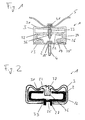
- Figur 1
- die schematische Darstellung eines Profilmoduls mit befestigtem Plattenelement im Schnitt;
- Figur 2
- die schematische Darstellung eines Profilmoduls in einer weiteren Ausführungsform im Schnitt;
- Figur 3
- die schematische Darstellung eines Profilmoduls in einer dritten Ausführungsform im Schnitt und
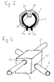
- Figur 4
- die schematische Darstellung eines Profilmoduls mit zwei orthogo- nal zueinander, übereinander durchgeführten Führungsprofilen.
- Das als Ausführungsbeispiel gewählte Profilmodul 1 besteht im Wesentlichen aus einem Führungsprofil 2, auf dem mehrere Schlittenelemente 3 schwimmend angeordnet sind. Unter einer "schwimmenden Lagerung" ist nachfolgend eine in horizontaler und vertikaler Richtung bewegliche Lagerung zu verstehen.
- Das Führungsprofil 2 ist im Ausführungsbeispiel im Wesentlichen als C-Profil ausgebildet. An seiner Oberseite 21 ist in das Führungsprofil 2 eine in Längsrichtung durchgehende spaltartige Öffnung 22 eingebracht. Die Öffnung 22 dient dem Durchtritt eines Absatzes 32 der Schlittenelemente 3. Im Ausführungsbeispiel gemäß
Figur 1 sind im Übergang zu seiner der Oberseite 21 gegenüberliegend angeordneten Bodenseite 23 gegenüberliegend Hinterschnitte 24 zum Eingriff von Schlittenelementen 3 vorgesehen. Die Bodenseite 23 des Führungsprofils 3 ist zu beiden Längsseiten des Führungsprofils 2 verlängert nach außen überstehend ausgebildet, so dass zusammen mit einem aufgesetzten Schlittenelement 3 im Wesentlichen ein Rechteckquerschnitt gebildet ist. Die Schlittenelemente 3 sind in der Bodenseite 23 des Führungsprofils 2 Bohrungen 25 zur Durchführung von Befestigungsschrauben 4 eingebracht. - Das Schlittenelement 3 ist im Ausführungsbeispiel im Wesentlichen in Art eines C-Profils ausgebildet. Dabei ist parallel zu seiner dem Führungsprofil 2 abgewandten Bodenseite 31 eine Zwischenwand 32 angeformt. Mittig sind Bodenseite 31 und Zwischenwand 32 über zwei parallel zueinander angeordnete Stege 33 verbunden, zwischen denen eine Bohrung 34 zur Einbringung einer Schraube 41 eingebracht ist. Die Schraube 41 dient der Befestigung eines Plattenelements 5 auf dem Schlittenelement 3. Das Schlittenelement 3 ist derart ausgebildet, dass der Abstand seiner Seitenwände 34 größer ist als der Außenabstand der Seitenwände 26 des Führungsprofils 2. Im montierten Zustand greifen die freien Stege 35 des C-profilartigen Schlittenelements 3 in die Hinterschnitte 24 des Führungsprofils 2 ein. Dabei ist das Schlittenelement 3 auf dem Führungsprofil 2 sowohl in Längs- als auch in Querrichtung auf dem Führungsprofil verschiebbar, so dass eine schwimmende Lagerung des Schlittenelements 3 auf dem Führungsprofil 2 erzielt ist.
Im Ausführungsbeispiel gemäßFigur 2 ist das Führungsprofil 2 in Form eines C-Profils ausgebildet, wobei mittig an dessen Bodenseite 23 parallel zueinander zwei Stege 27 angeformt sind. Zwischen den Stegen 27 sind in Bodenseite 23 Bohrungen 25 zur Durchführung einer Befestigungsschraube 4 eingebracht. Auch das Schlittenelement 3 ist im Ausführungsbeispiel gemäßFigur 2 weitgehend in Art eines C-Profils ausgebildet. Mittig seiner geschlossenen Bodenseite 31 ist in Richtung des Führungsprofils 3 ein Absatz 36 eingeformt, der durch die Öffnung 22 des Führungsprofils 2 hindurchtritt. In dem Absatz 36 ist eine Bohrung 37 zur Durchführung einer Schraube 41 zur Befestigung eines Plattenelements eingebracht. Beidseitig des Absatzes 36 sind in das Schlittenelement 3 in Längsrichtung Einbuchtungen 38 vorgesehen. Die Einbuchtungen 38 bewirken eine Beabstandung des aufzunehmenden Plattenelements, wie sie im Ausführungsbeispiel gemäßFigur 1 durch die Zwischenwand 32 bewirkt ist. - Im Ausführungsbeispiel gemäß
Figur 3 weist das Führungsprofil 3 im Wesentlichen einen Kreisquerschnitt auf, wobei an seiner dem Schlittenelement 3 zugewandten Seite eine Öffnung 22 in Form eines durchgehenden Längsschlitzes eingebracht ist. An seiner der Öffnung 22 gegenüberliegenden Seite sind an dem Führungsprofil 2 beabstandet zueinander zwei Stege 27 angeformt. Zwischen den Stegen 27 sind Bohrungen 25 zur Durchführungen von Befestigungsschrauben eingebracht. Das Schlittenelement 3 weist im Ausführungsbeispiel gemäßFigur 3 ebenfalls einen Kreisquerschnitt auf, in den eine schlitzartige Öffnung 39 eingebracht ist. der Innendurchmesser des Schlittenelements 3 ist dabei größer als der Außendurchmesser des Führungsprofils 3, wobei der Abstand der schlitzartigen Öffnung 39 größer ist, als das Außenmaß der beabstandet an dem Führungsprofil 2 angeformten Stege 27. An seiner der Öffnung 39 gegenüberliegenden Oberseite ist an dem Schlittenelement 3 ein Absatz 36 angeformt, der in die Öffnung 22 des Führungsprofils 2 eingreift. Der Absatz 36 ist mit einer Bohrung 37 zur Aufnahme einer Schraube 41 zur Befestigung eines Plattenelements 5 versehen. - Im Ausführungsbeispiel gemäß
Figur 4 ist das Schlittenelement 3 im Wesentlichen quaderförmig ausgebildet. In das Schlittenelement 3 sind orthogonal zueinander in vertikaler Richtung beabstandet zwei Durchführungen 30 mit kreisrundem Querschnitt eingebracht. Die Durchführungen 30 dienen der Aufnahme von zwei Führungsprofilen 2, welche im Ausführungsbeispiel gemäßFigur 4 als Rohrprofile mit Kreisquerschnitt ausgebildet sind. Der Außendurchmesser der Führungsprofile 2 ist dabei kleiner als der Innendurchmesser der Durchführungen 30 des Schlittenelements 3. Im Ausführungsbeispiel gemäßFigur 4 übernimmt das zu unterst angeordnete Führungsprofil 2 die Funktion des Sparrens einer Dachkonstruktion. Die orthogonal zu diesem Führungsprofil 2 angeordnete Führungsprofil 2' übernimmt die Funktion der Latte. Mit Hilfe des Schlittenelements gemäßFigur 4 ist eine schwimmende Verbindung von Sparren und Latte in einer Dachkonstruktion ermöglicht. Das - nicht dargestellte - Plattenelement wird hier auf den Schlittenelementen 3 befestigt. Durch die schwimmende Verbindung der Profile 2, 2' mit Sparren- bzw. Lattenfunktion sind Geräuschentwicklungen auf Grund von Verformungen der auf den Schwimmelementen 3 befestigten Plattenelemente durch thermische Einwirkung vermieden.
Claims (11)
- Dachkonstruktion, umfassend beabstandet zueinander angeordnete Sparren, auf denen quer zu diesen beabstandet zueinander Latten zur Aufnahme von Plattenelementen befestigt sind, wobei die Latten zumindest teilweise Profilmodule (1) sind, umfassend ein Führungsprofil (2), das von wenigstens einem Schlittenelement (3) zumindest teilweise umschlossen ist, wobei das Schlittenelement (3) auf dem Führungsprofil (2) in wenigstens zwei Richtungen bewegbar ist dadurch gekennzeichnet, dass des Schlittenelement (3) der Befestigung der Plattenelemente auf dem Führungsprofil (2) dient, und das Führungsprofil (2) außen an zwei gegenüberliegenden Seiten jeweils einen Hinterschnitt (24) aufweist, in den das Schlittenelement (3) eingreift.
- Dachkonstruktion nach Anspruch 1 dadurch gekennzeichnet, dass das Führungsprofil (2) an seiner dem Schlittenelement (3) zugewandten Oberseite (21) wenigstens eine Öffnung (22) aufweist.
- Dachkonstruktion nach Anspruch 2, dadurch gekennzeichnet, dass die Öffnung (22) als Schlitz ausgeführt ist, welcher sich in Längsrichtung über das gesamte Führungsprofil (2) erstreckt.
- Dachkonstruktion nach Anspruch 2 oder 3, dadurch gekennzeichnet, dass das Schlittenelement (3) einen Absatz (36) aufweist, der durch die Öffnung (22) des Führungsprofils (2) hindurchragt.
- Dachkonstruktion nach Anspruch 4, dadurch gekennzeichnet, dass in dem Absatz (36) eine Bohrung (37) zum Einbringen einer Schraube (4) eingebracht ist.
- Dachkonstruktion nach einem der vorgenannten Ansprüche, dadurch gekennzeichnet, dass das Schlittenelement (3) als C-Profilteil ausgebildet ist, wobei die freien Kanten (35) des C-Profils jeweils in einen Hinterschnitt (24) des Führungsprofils (2) eingreift.
- Dachkonstruktion nach Anspruch 1, dadurch gekennzeichnet, dass das Schlittenelement (3) zwei Durchführungen (30) aufweist, durch die jeweils ein Führungsprofil (2') bewegbar geführt ist.
- Dachkonstruktion nach Anspruch 7, dadurch gekennzeichnet, dass die Durchführungen (30) übereinander, winklig zueinander in dem Schlittenelement (3) angeordnet sind.
- Dachkonstruktion nach Anspruch 8, dadurch gekennzeichnet, dass die Durchführungen (30) orthogonal zueinander angeordnet sind.
- Dachkonstruktion nach Anspruch 1, dadurch gekennzeichnet, dass die Sparren zumindest teilweise Profilmodule (1) sind, umfassend ein Führungsprofil (2), das von wenigstens einem Schlittenelement (3) zumindest teilweise umschlossen ist, wobei das Schlittenelement (3) auf dem Führungsprofil (2) in wenigstens zwei Richtungen bewegbar ist.
- Dachkonstruktion nach Anspruch 1, dadurch gekennzeichnet, dass die Sparren zumindest teilweise zwei in Längsrichtung übereinander angeordnete Führungsprofile (2) umfassen, wobei ein zweites Führungsprofil (2) mit wenigstens einem auf einem ersten Führungsprofil (2) schwimmend gelagerten Schlittenelement (3) verbunden ist.
Priority Applications (1)
| Application Number | Priority Date | Filing Date | Title |
|---|---|---|---|
| EP20090013994 EP2320004B1 (de) | 2009-11-07 | 2009-11-07 | Profilmodul zur Herstellung einer Dachkonstruktion |
Applications Claiming Priority (1)
| Application Number | Priority Date | Filing Date | Title |
|---|---|---|---|
| EP20090013994 EP2320004B1 (de) | 2009-11-07 | 2009-11-07 | Profilmodul zur Herstellung einer Dachkonstruktion |
Publications (2)
| Publication Number | Publication Date |
|---|---|
| EP2320004A1 EP2320004A1 (de) | 2011-05-11 |
| EP2320004B1 true EP2320004B1 (de) | 2012-05-30 |
Family
ID=41718924
Family Applications (1)
| Application Number | Title | Priority Date | Filing Date |
|---|---|---|---|
| EP20090013994 Active EP2320004B1 (de) | 2009-11-07 | 2009-11-07 | Profilmodul zur Herstellung einer Dachkonstruktion |
Country Status (1)
| Country | Link |
|---|---|
| EP (1) | EP2320004B1 (de) |
Family Cites Families (4)
| Publication number | Priority date | Publication date | Assignee | Title |
|---|---|---|---|---|
| US714101A (en) * | 1902-09-22 | 1902-11-18 | Florance Meredith David | Scaffolding. |
| FR1452957A (fr) | 1965-09-24 | 1966-04-15 | Perfectionnements à la fixation de plaques sur des supports | |
| DE3342731A1 (de) * | 1983-11-25 | 1985-06-05 | SFS Fritz Haas GmbH & Co KG, 6370 Oberursel | Fassaden- und dach-unterkonstruktion |
| US6082070A (en) | 1998-10-30 | 2000-07-04 | Jen; Michael T. | Easy-to-assembly patio construction |
-
2009
- 2009-11-07 EP EP20090013994 patent/EP2320004B1/de active Active
Also Published As
| Publication number | Publication date |
|---|---|
| EP2320004A1 (de) | 2011-05-11 |
Similar Documents
| Publication | Publication Date | Title |
|---|---|---|
| DE60314459T2 (de) | Bauelement für die mantelbetonbauweise | |
| EP3315874B1 (de) | Geteilt ausgebildeter dachhaken für hohe belastungen | |
| DE102012007535A1 (de) | Verbindungselement zum Verbinden eines ersten Bauteils eines Gestells einer Photovoltaik- und/oder Solarthermieanlage mit einem zweiten Bauteil und Gestell einer Photovoltalk- und/oder Solarthermieanlage | |
| EP3715561B1 (de) | Überdachungssystem sowie trägermodul hierfür | |
| DE102010010249A1 (de) | Solarmodulanordnung | |
| AT509484B1 (de) | Haltevorrichtung zum verbinden von profilen zu einem flächigen wandelement | |
| EP2320004B1 (de) | Profilmodul zur Herstellung einer Dachkonstruktion | |
| EP2290169B1 (de) | Profilmodul zur Herstellung einer Dachkonstruktion | |
| DE69005395T2 (de) | Bausystem. | |
| EP0960985A2 (de) | I-förmiger Träger für Gebäudekonstruktionen | |
| EP2853670B1 (de) | Laufschiene für eine Schiebetür | |
| DE202022103790U1 (de) | Gebäudedeckenraster-Trockenaufhängungsstruktur | |
| EP2423405B1 (de) | Stehfalzeindeckung | |
| DE102014104542A1 (de) | Befestigungsvorrichtung für Trockenbauwände | |
| DE102017120676B4 (de) | Deckenverkleidungssystem | |
| AT508759A4 (de) | Bauelement für wand- und deckensysteme | |
| DE102020125702B4 (de) | Belag für den Außenbereich | |
| EP2388485B1 (de) | Führungsschienensegment | |
| DE10200251A1 (de) | Schalungsbauteil und Sturzkasten | |
| EP3617415B1 (de) | Durchstanzbewehrungselement und bauwerk mit einer platte mit einem durchstanzbewehrungselement | |
| DE102006012276A1 (de) | Befestigungsvorrichtung für Solarmodule mit einem Dachhaken | |
| DE2928751A1 (de) | Traggeruest fuer ein zelt o.dgl. | |
| EP4585382A1 (de) | Vorfertigungsvorrichtung zur vorfertigung von holzbau-fertigbauteilen | |
| DE202010014962U1 (de) | Profilmodul zur Herstellung einer Dachkonstruktion | |
| DE102006012254A1 (de) | Befestigungsvorrichtung für Solarmodule mit einem Grundträger |
Legal Events
| Date | Code | Title | Description |
|---|---|---|---|
| PUAI | Public reference made under article 153(3) epc to a published international application that has entered the european phase |
Free format text: ORIGINAL CODE: 0009012 |
|
| AK | Designated contracting states |
Kind code of ref document: A1 Designated state(s): AT BE BG CH CY CZ DE DK EE ES FI FR GB GR HR HU IE IS IT LI LT LU LV MC MK MT NL NO PL PT RO SE SI SK SM TR |
|
| AX | Request for extension of the european patent |
Extension state: AL BA RS |
|
| 17P | Request for examination filed |
Effective date: 20111107 |
|
| GRAP | Despatch of communication of intention to grant a patent |
Free format text: ORIGINAL CODE: EPIDOSNIGR1 |
|
| GRAS | Grant fee paid |
Free format text: ORIGINAL CODE: EPIDOSNIGR3 |
|
| GRAA | (expected) grant |
Free format text: ORIGINAL CODE: 0009210 |
|
| AK | Designated contracting states |
Kind code of ref document: B1 Designated state(s): AT BE BG CH CY CZ DE DK EE ES FI FR GB GR HR HU IE IS IT LI LT LU LV MC MK MT NL NO PL PT RO SE SI SK SM TR |
|
| REG | Reference to a national code |
Ref country code: GB Ref legal event code: FG4D Free format text: NOT ENGLISH |
|
| REG | Reference to a national code |
Ref country code: CH Ref legal event code: EP |
|
| REG | Reference to a national code |
Ref country code: AT Ref legal event code: REF Ref document number: 560156 Country of ref document: AT Kind code of ref document: T Effective date: 20120615 |
|
| REG | Reference to a national code |
Ref country code: IE Ref legal event code: FG4D Free format text: LANGUAGE OF EP DOCUMENT: GERMAN |
|
| REG | Reference to a national code |
Ref country code: DE Ref legal event code: R096 Ref document number: 502009003655 Country of ref document: DE Effective date: 20120726 |
|
| REG | Reference to a national code |
Ref country code: NL Ref legal event code: VDEP Effective date: 20120530 |
|
| REG | Reference to a national code |
Ref country code: LT Ref legal event code: MG4D Effective date: 20120530 |
|
| PG25 | Lapsed in a contracting state [announced via postgrant information from national office to epo] |
Ref country code: LT Free format text: LAPSE BECAUSE OF FAILURE TO SUBMIT A TRANSLATION OF THE DESCRIPTION OR TO PAY THE FEE WITHIN THE PRESCRIBED TIME-LIMIT Effective date: 20120530 Ref country code: SE Free format text: LAPSE BECAUSE OF FAILURE TO SUBMIT A TRANSLATION OF THE DESCRIPTION OR TO PAY THE FEE WITHIN THE PRESCRIBED TIME-LIMIT Effective date: 20120530 Ref country code: NO Free format text: LAPSE BECAUSE OF FAILURE TO SUBMIT A TRANSLATION OF THE DESCRIPTION OR TO PAY THE FEE WITHIN THE PRESCRIBED TIME-LIMIT Effective date: 20120830 Ref country code: CY Free format text: LAPSE BECAUSE OF FAILURE TO SUBMIT A TRANSLATION OF THE DESCRIPTION OR TO PAY THE FEE WITHIN THE PRESCRIBED TIME-LIMIT Effective date: 20120530 Ref country code: FI Free format text: LAPSE BECAUSE OF FAILURE TO SUBMIT A TRANSLATION OF THE DESCRIPTION OR TO PAY THE FEE WITHIN THE PRESCRIBED TIME-LIMIT Effective date: 20120530 Ref country code: IS Free format text: LAPSE BECAUSE OF FAILURE TO SUBMIT A TRANSLATION OF THE DESCRIPTION OR TO PAY THE FEE WITHIN THE PRESCRIBED TIME-LIMIT Effective date: 20120930 |
|
| PG25 | Lapsed in a contracting state [announced via postgrant information from national office to epo] |
Ref country code: SI Free format text: LAPSE BECAUSE OF FAILURE TO SUBMIT A TRANSLATION OF THE DESCRIPTION OR TO PAY THE FEE WITHIN THE PRESCRIBED TIME-LIMIT Effective date: 20120530 Ref country code: HR Free format text: LAPSE BECAUSE OF FAILURE TO SUBMIT A TRANSLATION OF THE DESCRIPTION OR TO PAY THE FEE WITHIN THE PRESCRIBED TIME-LIMIT Effective date: 20120530 Ref country code: GR Free format text: LAPSE BECAUSE OF FAILURE TO SUBMIT A TRANSLATION OF THE DESCRIPTION OR TO PAY THE FEE WITHIN THE PRESCRIBED TIME-LIMIT Effective date: 20120831 Ref country code: LV Free format text: LAPSE BECAUSE OF FAILURE TO SUBMIT A TRANSLATION OF THE DESCRIPTION OR TO PAY THE FEE WITHIN THE PRESCRIBED TIME-LIMIT Effective date: 20120530 |
|
| PG25 | Lapsed in a contracting state [announced via postgrant information from national office to epo] |
Ref country code: DK Free format text: LAPSE BECAUSE OF FAILURE TO SUBMIT A TRANSLATION OF THE DESCRIPTION OR TO PAY THE FEE WITHIN THE PRESCRIBED TIME-LIMIT Effective date: 20120530 Ref country code: NL Free format text: LAPSE BECAUSE OF FAILURE TO SUBMIT A TRANSLATION OF THE DESCRIPTION OR TO PAY THE FEE WITHIN THE PRESCRIBED TIME-LIMIT Effective date: 20120530 Ref country code: EE Free format text: LAPSE BECAUSE OF FAILURE TO SUBMIT A TRANSLATION OF THE DESCRIPTION OR TO PAY THE FEE WITHIN THE PRESCRIBED TIME-LIMIT Effective date: 20120530 Ref country code: RO Free format text: LAPSE BECAUSE OF FAILURE TO SUBMIT A TRANSLATION OF THE DESCRIPTION OR TO PAY THE FEE WITHIN THE PRESCRIBED TIME-LIMIT Effective date: 20120530 Ref country code: CZ Free format text: LAPSE BECAUSE OF FAILURE TO SUBMIT A TRANSLATION OF THE DESCRIPTION OR TO PAY THE FEE WITHIN THE PRESCRIBED TIME-LIMIT Effective date: 20120530 Ref country code: SK Free format text: LAPSE BECAUSE OF FAILURE TO SUBMIT A TRANSLATION OF THE DESCRIPTION OR TO PAY THE FEE WITHIN THE PRESCRIBED TIME-LIMIT Effective date: 20120530 |
|
| PG25 | Lapsed in a contracting state [announced via postgrant information from national office to epo] |
Ref country code: PT Free format text: LAPSE BECAUSE OF FAILURE TO SUBMIT A TRANSLATION OF THE DESCRIPTION OR TO PAY THE FEE WITHIN THE PRESCRIBED TIME-LIMIT Effective date: 20121001 Ref country code: IT Free format text: LAPSE BECAUSE OF FAILURE TO SUBMIT A TRANSLATION OF THE DESCRIPTION OR TO PAY THE FEE WITHIN THE PRESCRIBED TIME-LIMIT Effective date: 20120530 Ref country code: PL Free format text: LAPSE BECAUSE OF FAILURE TO SUBMIT A TRANSLATION OF THE DESCRIPTION OR TO PAY THE FEE WITHIN THE PRESCRIBED TIME-LIMIT Effective date: 20120530 |
|
| PLBE | No opposition filed within time limit |
Free format text: ORIGINAL CODE: 0009261 |
|
| STAA | Information on the status of an ep patent application or granted ep patent |
Free format text: STATUS: NO OPPOSITION FILED WITHIN TIME LIMIT |
|
| PG25 | Lapsed in a contracting state [announced via postgrant information from national office to epo] |
Ref country code: ES Free format text: LAPSE BECAUSE OF FAILURE TO SUBMIT A TRANSLATION OF THE DESCRIPTION OR TO PAY THE FEE WITHIN THE PRESCRIBED TIME-LIMIT Effective date: 20120910 |
|
| 26N | No opposition filed |
Effective date: 20130301 |
|
| BERE | Be: lapsed |
Owner name: FRIEDRICH VON LIEN A.G. Effective date: 20121130 |
|
| REG | Reference to a national code |
Ref country code: DE Ref legal event code: R097 Ref document number: 502009003655 Country of ref document: DE Effective date: 20130301 |
|
| PG25 | Lapsed in a contracting state [announced via postgrant information from national office to epo] |
Ref country code: BG Free format text: LAPSE BECAUSE OF FAILURE TO SUBMIT A TRANSLATION OF THE DESCRIPTION OR TO PAY THE FEE WITHIN THE PRESCRIBED TIME-LIMIT Effective date: 20120830 |
|
| REG | Reference to a national code |
Ref country code: IE Ref legal event code: MM4A |
|
| REG | Reference to a national code |
Ref country code: FR Ref legal event code: ST Effective date: 20130731 |
|
| PG25 | Lapsed in a contracting state [announced via postgrant information from national office to epo] |
Ref country code: BE Free format text: LAPSE BECAUSE OF NON-PAYMENT OF DUE FEES Effective date: 20121130 |
|
| PG25 | Lapsed in a contracting state [announced via postgrant information from national office to epo] |
Ref country code: IE Free format text: LAPSE BECAUSE OF NON-PAYMENT OF DUE FEES Effective date: 20121107 |
|
| PG25 | Lapsed in a contracting state [announced via postgrant information from national office to epo] |
Ref country code: MT Free format text: LAPSE BECAUSE OF FAILURE TO SUBMIT A TRANSLATION OF THE DESCRIPTION OR TO PAY THE FEE WITHIN THE PRESCRIBED TIME-LIMIT Effective date: 20120530 Ref country code: FR Free format text: LAPSE BECAUSE OF NON-PAYMENT OF DUE FEES Effective date: 20121130 |
|
| PG25 | Lapsed in a contracting state [announced via postgrant information from national office to epo] |
Ref country code: MC Free format text: LAPSE BECAUSE OF NON-PAYMENT OF DUE FEES Effective date: 20121130 Ref country code: TR Free format text: LAPSE BECAUSE OF FAILURE TO SUBMIT A TRANSLATION OF THE DESCRIPTION OR TO PAY THE FEE WITHIN THE PRESCRIBED TIME-LIMIT Effective date: 20120530 |
|
| PG25 | Lapsed in a contracting state [announced via postgrant information from national office to epo] |
Ref country code: SM Free format text: LAPSE BECAUSE OF FAILURE TO SUBMIT A TRANSLATION OF THE DESCRIPTION OR TO PAY THE FEE WITHIN THE PRESCRIBED TIME-LIMIT Effective date: 20120530 Ref country code: LU Free format text: LAPSE BECAUSE OF NON-PAYMENT OF DUE FEES Effective date: 20121107 |
|
| REG | Reference to a national code |
Ref country code: CH Ref legal event code: PL |
|
| GBPC | Gb: european patent ceased through non-payment of renewal fee |
Effective date: 20131107 |
|
| PG25 | Lapsed in a contracting state [announced via postgrant information from national office to epo] |
Ref country code: CH Free format text: LAPSE BECAUSE OF NON-PAYMENT OF DUE FEES Effective date: 20131130 Ref country code: HU Free format text: LAPSE BECAUSE OF FAILURE TO SUBMIT A TRANSLATION OF THE DESCRIPTION OR TO PAY THE FEE WITHIN THE PRESCRIBED TIME-LIMIT Effective date: 20091107 Ref country code: LI Free format text: LAPSE BECAUSE OF NON-PAYMENT OF DUE FEES Effective date: 20131130 |
|
| PG25 | Lapsed in a contracting state [announced via postgrant information from national office to epo] |
Ref country code: GB Free format text: LAPSE BECAUSE OF NON-PAYMENT OF DUE FEES Effective date: 20131107 |
|
| PG25 | Lapsed in a contracting state [announced via postgrant information from national office to epo] |
Ref country code: MK Free format text: LAPSE BECAUSE OF FAILURE TO SUBMIT A TRANSLATION OF THE DESCRIPTION OR TO PAY THE FEE WITHIN THE PRESCRIBED TIME-LIMIT Effective date: 20120530 |
|
| REG | Reference to a national code |
Ref country code: AT Ref legal event code: MM01 Ref document number: 560156 Country of ref document: AT Kind code of ref document: T Effective date: 20141107 |
|
| PG25 | Lapsed in a contracting state [announced via postgrant information from national office to epo] |
Ref country code: AT Free format text: LAPSE BECAUSE OF NON-PAYMENT OF DUE FEES Effective date: 20141107 |
|
| PGFP | Annual fee paid to national office [announced via postgrant information from national office to epo] |
Ref country code: DE Payment date: 20251024 Year of fee payment: 17 |