EP2319790A1 - Dispositif d'enroulement à commande manuelle - Google Patents
Dispositif d'enroulement à commande manuelle Download PDFInfo
- Publication number
- EP2319790A1 EP2319790A1 EP10354057A EP10354057A EP2319790A1 EP 2319790 A1 EP2319790 A1 EP 2319790A1 EP 10354057 A EP10354057 A EP 10354057A EP 10354057 A EP10354057 A EP 10354057A EP 2319790 A1 EP2319790 A1 EP 2319790A1
- Authority
- EP
- European Patent Office
- Prior art keywords
- rotation
- drum
- axis
- winding device
- operating handle
- Prior art date
- Legal status (The legal status is an assumption and is not a legal conclusion. Google has not performed a legal analysis and makes no representation as to the accuracy of the status listed.)
- Granted
Links
Images


Classifications
-
- B—PERFORMING OPERATIONS; TRANSPORTING
- B65—CONVEYING; PACKING; STORING; HANDLING THIN OR FILAMENTARY MATERIAL
- B65H—HANDLING THIN OR FILAMENTARY MATERIAL, e.g. SHEETS, WEBS, CABLES
- B65H75/00—Storing webs, tapes, or filamentary material, e.g. on reels
- B65H75/02—Cores, formers, supports, or holders for coiled, wound, or folded material, e.g. reels, spindles, bobbins, cop tubes, cans, mandrels or chucks
- B65H75/34—Cores, formers, supports, or holders for coiled, wound, or folded material, e.g. reels, spindles, bobbins, cop tubes, cans, mandrels or chucks specially adapted or mounted for storing and repeatedly paying-out and re-storing lengths of material provided for particular purposes, e.g. anchored hoses, power cables
- B65H75/38—Cores, formers, supports, or holders for coiled, wound, or folded material, e.g. reels, spindles, bobbins, cop tubes, cans, mandrels or chucks specially adapted or mounted for storing and repeatedly paying-out and re-storing lengths of material provided for particular purposes, e.g. anchored hoses, power cables involving the use of a core or former internal to, and supporting, a stored package of material
- B65H75/44—Constructional details
- B65H75/4481—Arrangements or adaptations for driving the reel or the material
- B65H75/4492—Manual drives
-
- B—PERFORMING OPERATIONS; TRANSPORTING
- B65—CONVEYING; PACKING; STORING; HANDLING THIN OR FILAMENTARY MATERIAL
- B65H—HANDLING THIN OR FILAMENTARY MATERIAL, e.g. SHEETS, WEBS, CABLES
- B65H75/00—Storing webs, tapes, or filamentary material, e.g. on reels
- B65H75/02—Cores, formers, supports, or holders for coiled, wound, or folded material, e.g. reels, spindles, bobbins, cop tubes, cans, mandrels or chucks
- B65H75/34—Cores, formers, supports, or holders for coiled, wound, or folded material, e.g. reels, spindles, bobbins, cop tubes, cans, mandrels or chucks specially adapted or mounted for storing and repeatedly paying-out and re-storing lengths of material provided for particular purposes, e.g. anchored hoses, power cables
- B65H75/38—Cores, formers, supports, or holders for coiled, wound, or folded material, e.g. reels, spindles, bobbins, cop tubes, cans, mandrels or chucks specially adapted or mounted for storing and repeatedly paying-out and re-storing lengths of material provided for particular purposes, e.g. anchored hoses, power cables involving the use of a core or former internal to, and supporting, a stored package of material
- B65H75/40—Cores, formers, supports, or holders for coiled, wound, or folded material, e.g. reels, spindles, bobbins, cop tubes, cans, mandrels or chucks specially adapted or mounted for storing and repeatedly paying-out and re-storing lengths of material provided for particular purposes, e.g. anchored hoses, power cables involving the use of a core or former internal to, and supporting, a stored package of material mobile or transportable
-
- B—PERFORMING OPERATIONS; TRANSPORTING
- B65—CONVEYING; PACKING; STORING; HANDLING THIN OR FILAMENTARY MATERIAL
- B65H—HANDLING THIN OR FILAMENTARY MATERIAL, e.g. SHEETS, WEBS, CABLES
- B65H75/00—Storing webs, tapes, or filamentary material, e.g. on reels
- B65H75/02—Cores, formers, supports, or holders for coiled, wound, or folded material, e.g. reels, spindles, bobbins, cop tubes, cans, mandrels or chucks
- B65H75/34—Cores, formers, supports, or holders for coiled, wound, or folded material, e.g. reels, spindles, bobbins, cop tubes, cans, mandrels or chucks specially adapted or mounted for storing and repeatedly paying-out and re-storing lengths of material provided for particular purposes, e.g. anchored hoses, power cables
- B65H75/38—Cores, formers, supports, or holders for coiled, wound, or folded material, e.g. reels, spindles, bobbins, cop tubes, cans, mandrels or chucks specially adapted or mounted for storing and repeatedly paying-out and re-storing lengths of material provided for particular purposes, e.g. anchored hoses, power cables involving the use of a core or former internal to, and supporting, a stored package of material
- B65H75/44—Constructional details
- B65H75/4457—Arrangements of the frame or housing
- B65H75/4468—Tubular frame
Definitions
- the invention relates to a manually operated winding device comprising an operating handle rotatably mounted about a first axis of rotation integral with a frame.
- a drum is rotated by said handle through a drive mechanism including latching means having a rotatable ratchet.
- Said rocker is intended to cooperate with a toothed pinion attached to the drum to drive it in rotation by oscillation of the operating handle.
- Said pinion and said drum are mounted in rotation about a second axis of rotation integral with the frame.
- the use of a drum for winding a material such as electric cable or pipe is widespread.
- the drum is generally mounted on an axis of rotation fixed to a base or a frame.
- a first solution consists in equipping the manual winder with elastic return means. These elastic return means are armed when the cable is unrolled from the drum.
- a click system prevents the cable wraps inadvertently under the effect of the elastic means.
- the reel further comprises unlocking means of the click system allowing the controlled winding of the wire on the drum.
- This type of retractor is generally fixed on a support so that the user can pull the cable by exerting a force sufficient to oppose that of the elastic means. This type of reel thus has the disadvantage of being non-transportable easily and being relatively heavy.
- this solution is used for short cable length.
- a second solution is to manually actuate the rotation of the drum to wind the cable on the drum.
- the drum generally comprises a more or less ergonomic handle attached directly to a face of said drum. The user activates manually and directly the rotation of the drum about its axis of rotation via the handle.
- the handle being preferably placed on the periphery of the drum, this forces the user to perform hand and arm rotation movements.
- This second solution is particularly used when the manual winder is transportable.
- the invention therefore aims to overcome the drawbacks of the state of the art, so as to provide a manually controlled winding device comprising reliable and effective winding means.
- the drive mechanism comprises means for intermediate drive of the rotary ratchet rocker, said intermediate means being rotatably mounted about a third axis of fixed rotation and being rotated by the operating handle.
- the rotating ratchet rocker is rotatably mounted about a fourth movable axis of rotation and is integral with the intermediate drive means.
- the four axes of rotation are parallel, the first, second and third axes of rotation being arranged in the same plane and the third axis of rotation being placed between two others.
- the relative position of the fourth axis of rotation with respect to the first, second and third axes of rotation determines a rotational ratio between the angle of rotation of the operating handle and the rotation angle of the drum.
- the rotation ratio is greater than 1 if the distance between the first and fourth axis of rotation is greater than the distance between the first and second axes of rotation, the distance between the second and third axes of rotation being fixed.
- the operating handle comprises a guide pin that can move in a guide aperture integral with the frame, the guide opening extends in a circular arc having the center of the first axis of rotation.
- the guide opening is positioned in a support flange integral with the frame.
- the operating handle comprises a telescopic arm, the guide pin being carried on a movable section of the telescopic arm and being guided in translation in a locking position to block the rotation of said handle and the drum.
- the guide opening extends from one end of the arc in a radial direction towards the first axis of rotation.
- the operating handle comprises disengaging means for releasing the rotary ratchet of the toothed pinion so that the operating handle no longer rotates the drum.
- the rotary ratchet rocker has a return spring whose one end is secured to the intermediate drive means and the other end of the rotary ratchet rocker, the return spring being intended to push the ratchet rocker rotatable to the toothed pinion so as to engage a tooth of said pinion when the operating handle oscillates from a first to a second position.
- the manually-operated winding device of a roll-up element comprises a drum 1 rotatably mounted on a frame 5.
- the drum 1 is rotatably mounted about a second axis of rotation Z2 secured to the frame 5.
- the frame 5 is constituted by a folded tube comprising at least one seating area, a fixing zone of the drum 1 and an attachment zone.
- the seating area is intended to rest on the ground and comprises at least two support surfaces spaced apart from each other and interconnected by a section of tube; said tube section connecting the bearing surfaces not in contact with the ground when the winding device is set. This specific bending of the tube at the bearing surfaces makes it possible to guarantee good stability of the winding device when the latter is placed on a non-planar surface.
- the drum attachment zone allows a nesting of said drum 1.
- the second axis of rotation Z2 is materialized either by an independent axis fixed on the bent tube of the frame, or by a portion of the bent tube. In the second case, the drum may comprise in its center an oblong hole 55 to allow its mounting.
- the attachment zone 300 has the shape of a handle allowing the transport of the winding device.
- the folded tube has the originality of rising to the operating handle 2 on the central axis of the drum. This folding creates a transport handle.
- the transport handles and maneuver 2 are then placed vertically above the winding device during maneuvers.
- the winding device comprises an operating handle 2 rotatably mounted about a first fixed axis of rotation Z1.
- the drum 1 is actuated in rotation by said handle via a drive mechanism.
- Said first axis of rotation is integral with the frame 5.
- said first axis can be secured to the frame 5 by means of a flange 6.
- Said drive mechanism comprises latching means comprising a pinion gear 31 secured directly or indirectly to the drum 1.
- Said pinion has teeth 36 distributed on a radial face of the drum 1.
- Said pinion and the drum are mounted in rotation about the second axis of rotation Z2 integral with the frame 5.
- the toothed pinion 31 is directly attached to the drum 1.
- the drum is made of molded plastic and the teeth 36 are molded concomitantly with the drum and therefore part of the drum 1.
- the latching means further comprise a rotary ratchet rocker 32 intended to cooperate with the pinion gear 31 to drive it in rotation by oscillation of the operating handle 2 between a first and a second operating position.
- the drive mechanism comprises intermediate drive means 34 of the rotary ratchet rocker 32.
- Said intermediate drive means 34 are rotatably mounted about a third axis of rotation Z3 fixed and are rotated by the handle maneuver 2.
- the rotary ratchet rocker 32 is secured to the rotary intermediate drive means 34.
- Said rocker is then rotated at least partially around a fourth axis of rotation Z4 mobile.
- the rotary ratchet rocker 32 comprises a first notch intended to collaborate with teeth 36 of the pinion gear.
- the rotary ratchet rocker 32 has a return spring 33, one end of which is integral with the intermediate drive means 34 and the other of the rotary ratchet rocker 32.
- the return spring 33 is intended to push the rocker to rotary ratchet 32 towards the toothed pinion 31 so as to engage a tooth 36 of said pinion 31 when the operating handle 2 oscillates from a first to a second operating position.
- the first, second and third axes of rotation Z1, Z2, Z3 are arranged in the same plane and the third axis of rotation Z3 is preferably placed between two other axes.
- the four axes of rotation Z1, Z2, Z3, Z4 are advantageously parallel.
- the third axis of rotation Z3 is separated from the second axis of rotation Z2 by a distance Z1Z2.
- the relative position of the fourth axis of rotation Z4 vis-à-vis the first, second and third axes of rotation Z1, Z2, Z3 determines a rotational ratio R between the angle of rotation of the operating handle 2 and the rotation angle of the drum 1.
- the rotational ratio R is greater than one (R> 1) if the distance Z1 Z4 between the first and fourth axes of rotation is greater than the distance Z1Z2 between the first and second axes of rotation , the length of the ratchet rocker being fixed and the distance between the second and third axes of rotation Z2 and Z3 being fixed. The movement of the operating handle 2 is then multiplied.
- the rotational ratio R is less than one (R ⁇ 1) if the distance Z1Z4 between the first and fourth axes of rotation is smaller than the distance Z1Z2 between the first and second axes of rotation. The movement of the operating handle is then under-multiplied.
- the operation of the manually operated winding device is as follows.
- the drum 1 is then rotated. Due to the inertia of the drum and the fact that it is freely mounted on the second axis of rotation Z2, this rotational movement continues at the end of the first movement of the handle.
- the drum is already rotating.
- a first actuation phase if the movement of the operating handle 2 is regular then an acceleration of the rotation of the drum 1 is observed and thereby an increase in the rotational ratio R.
- a second phase if the movement of the operating handle 2 is regular then the rotational speed of the drum has a tendency to stabilize substantially.
- said rocker and said teeth have specific shapes and specially studied.
- optimal operation is achieved by minimizing the distance between the second and third axis of rotation Z2Z3. Reducing said distance makes it possible to avoid a deceleration at the end of the movement and consequently a tactile sensation of relaxation of the motor.
- the operating handle 2 comprises a guide pin 21 for limiting the rotational travel of the operating handle 2 between the first and second operating position.
- This lug is positioned in a guide opening 61.
- Said guide opening is integral with the frame and is preferably positioned in a support flange 6 secured to the frame 5.
- the guide opening 61 extends in a circular arc having for center the first axis of rotation Z1. Said pin can then move in a rotational movement between the first and the second operating position. At each operating position, said lug is abutting against the ends of the guide opening 61.
- the size of the circular arc conditions the amplitude of the movement of the operating handle 2.
- the arc of circle is equal to 60 °.
- the operating handle 2 comprises a telescopic arm, the guide pin 21 being carried on a movable portion of the telescopic arm 22.
- the guide opening 61 extends from one end of the telescopic arm 22. arc in a radial direction relative to the first axis of rotation Z1. The axial displacement of the movable section towards said axis of rotation causes the displacement of the guide pin in the guide opening 61 to a locking position.
- the guide pin 21 is then guided in translation in the locking position.
- a locking pin 25 positioned on the movable portion of the telescopic arm 22 is placed between two locking tabs 38 to block any movement of said handle 2 and the drum 1.
- the drum preferably comprises a plurality of locking tabs 38 arranged uniformly on a circle having as a center the second axis of rotation Z2.
- the device comprises disengagement means 100 for releasing the rotary ratchet rocker 32 of the toothed pinion 31.
- the actuation of the disengagement means 100 prevents the drum from rotating between the second and first positions. operating by the operating handle 2.
- the winding device comprises a hooking system to ensure a stable position of the winding device on a support such as including the bars 570 of a scale.
- said system comprises a first element having a hooking zone 580 of a bar 570.
- the hooking zone 580 is preferably delimited by an upper stop 540 and a lower stop 530.
- said stops 540 530 are projecting from the tube constituting the frame 5 of the winding device.
- the space separating the two stops 530, 540 is substantially equal to the section of a bar 570 scale.
- Said hooking system comprises a second element 520 allowing a locking of the winding device on the support, in particular on the bar 570.
- the second element comprises a retractable elastic arm projecting relative to the first element so that it retracts when the winding device comes picking the bar 570 and that it folds behind said bar to ensure a secure hooking.
- the center of gravity of the winding device is advantageously placed so that an area of the frame 5 of the winding device can rest on the back of the ladder in a stable position.
Landscapes
- Storing, Repeated Paying-Out, And Re-Storing Of Elongated Articles (AREA)
- Operating, Guiding And Securing Of Roll- Type Closing Members (AREA)
Abstract
Description
- L'invention est relative à un dispositif d'enroulement à commande manuelle comprenant une poignée de manoeuvre montée en rotation autour d'un premier axe de rotation solidaire d'un bâti. Un tambour est actionné en rotation par ladite poignée par l'intermédiaire d'un mécanisme d'entrainement comprenant des moyens d'encliquetage ayant un basculeur à cliquet rotatif. Ledit basculeur est destiné à coopérer avec un pignon denté assujetti au tambour pour l'entrainer en rotation par oscillation de la poignée de manoeuvre. Ledit pignon et ledit tambour sont montés en rotation autour d'un second axe de rotation solidaire du bâti.
- L'utilisation d'un tambour pour enrouler un matériau tel que du câble électrique ou du tuyau est largement répandue. Le tambour est généralement monté sur un axe de rotation fixé à un socle ou un bâti.
- Lorsque le tambour est à commande manuelle, le déroulement ou dévidage du câble se fait généralement en tirant directement sur le câble. En outre, concernant l'enroulement du câble sur le tambour, plusieurs solutions connues s'offrent à l'utilisateur.
- Une première solution consiste à équiper l'enrouleur manuel de moyens élastiques de rappel. Ces moyens élastiques de rappel sont armés lorsque le câble est déroulé du tambour. Un système à cliquer permet d'éviter que le câble s'enroule malencontreusement sous l'effet des moyens élastiques. L'enrouleur comporte en outre des moyens de déverrouillage du système à cliquer autorisant l'enroulement contrôlé du fil sur le tambour. Ce type d'enrouleur est généralement fixé sur un support afin que l'utilisateur puisse tirer le câble en exerçant une force suffisante pour s'opposer à celle des moyens élastiques. Ce type d'enrouleur présente ainsi l'inconvénient d'être non transportable facilement et d'être relativement lourd. En outre, de part la limite élastique du ressort et de l'encombrement du système, cette solution est utilisée pour de faible longueur de câble.
- Une seconde solution consiste à actionner manuellement la rotation du tambour pour enrouler le câble sur le tambour. Le tambour comporte généralement une poignée plus ou moins ergonomique fixée directement sur une face dudit tambour. L'utilisateur actionne entraine manuellement et directement la rotation du tambour autour de son axe de rotation via la poignée. La poignée étant placée de préférence sur la périphérie du tambour, cela oblige l'utilisateur a effectué des mouvements de rotation de main et du bras. Cette seconde solution est particulière utilisé lorsque l'enrouleur manuel est transportable.
- D'autres solutions existent pour résoudre les problématiques d'enroulement mais elles sont peu robustes vis-à-vis des conditions d'utilisations difficiles car elles sont réalisées avec des mécanismes sensibles. La corde collecte la poussière est coince rapidement le mécanisme.
- L'invention vise donc à remédier aux inconvénients de l'état de la technique, de manière à proposer un dispositif d'enroulement à commande manuelle comportant des moyens d'enroulement fiables et efficaces.
- Le mécanisme d'entrainement selon l'invention comporte des moyens d'entrainement intermédiaires du basculeur à cliquet rotatif, lesdits moyens intermédiaires étant montés en rotation autour d'un troisième axe de rotation fixe et étant entrainés en rotation par la poignée de manoeuvre. Le basculeur à cliquet rotatif est monté en rotation autour d'un quatrième axe de rotation mobile et étant solidaire des moyens d'entrainement intermédiaires. Les quatre axes de rotation sont parallèles, les premier, second et troisième axes de rotation étant disposés dans un même plan et le troisième axe de rotation étant placé entre deux autres. La position relative du quatrième axe de rotation vis-à-vis des premier, second et troisième axes de rotation détermine un rapport de rotation entre l'angle de rotation de la poignée de manoeuvre et l'angle de rotation du tambour.
- Selon un mode de développement de l'invention, le rapport de rotation est supérieur à 1 si la distance entre le premier et quatrième axe de rotation est supérieure à la distance entre les premier et second axes de rotation, la distance entre les second et troisième axes de rotations étant fixes.
- Avantageusement, la poignée de manoeuvre comporte un ergot de guidage pouvant se déplacer dans une ouverture de guidage solidaire du bâti, l'ouverture de guidage s'étend selon un arc de cercle ayant pour centre le premier axe de rotation.
- De préférence, l'ouverture de guidage est positionnée dans un flasque de support solidaire du bâti.
- Selon un mode particulier de réalisation, la poignée de manoeuvre comporte un bras télescopique, l'ergot de guidage étant porté sur un tronçon mobile du bras télescopique et étant guidée en translation dans une position de verrouillage pour bloquer la rotation de la dite poignée et du tambour.
- Avantageusement, l'ouverture de guidage s'étend depuis une extrémité de l'arc de cercle selon une direction radiale en direction du premier axe de rotation.
- De préférence, la poignée de manoeuvre comporte des moyens de débrayage destinés à libérer le basculeur à cliquet rotatif du pignon denté de manière à ce que la poignée de manoeuvre n'entraine plus en rotation le tambour.
- De préférence, le basculeur à cliquet rotatif présente un ressort de rappel dont l'une des extrémités est solidaire des moyens d'entrainement intermédiaires et l'autre extrémité du basculeur à cliquet rotatif, le ressort de rappel étant destiné à pousser le basculeur à cliquet rotatif vers le pignon denté de manière à engrener une dent dudit pignon lorsque la poignée de manoeuvre oscille d'une première vers une seconde position.
- D'autres avantages et caractéristiques ressortiront plus clairement de la description qui va suivre d'un mode particulier de réalisation de l'invention, donné à titre d'exemple non limitatif, et représenté aux dessins annexés sur lesquels :
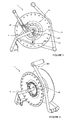
- La
figure 1 représente une vue de coté d'un dispositif d'enroulement à commande manuelle selon un mode préférentiel de réalisation de l'invention ; - La
figure 2 représente une vue en perspective du dispositif d'enroulement à commande manuelle selon lafigure 1 ; - Les
figures 3 et 4 représentent des vues éclatées en perspective de moyens d'entrainement du dispositif d'enroulement selon lafigure 1 ; - Les
figures 5 et 6 représentent des vues en perspective d'un dispositif d'enroulement selon un mode préférentiel de réalisation de l'invention ; - La
figure 7 représente un vue d'un dispositif d'enroulement selon l'invention positionné sur un support. - Selon un mode de réalisation de l'invention, le dispositif d'enroulement à commande manuelle d'un élément enroulable comporte un tambour 1 monté en rotation sur un bâti 5. Le tambour 1 est monté en rotation autour d'un second axe de rotation Z2 solidaire du bâti 5.
- Selon un mode particulier de réalisation tel que représenté sur les
figures 1 et 2 , le bâti 5 est constitué un tube plié comportant au moins une zone d'assise, une zone de fixation du tambour 1 et une zone d'accrochage. La zone d'assise est destinée à reposer sur le sol et comporte au moins deux surfaces d'appui distantes l'une de l'autre et reliées entre elles par une section de tube ; ladite section de tube reliant les surfaces d'appui n'étant pas au contact du sol lorsque le dispositif d'enroulement est posé. Ce pliage spécifique du tube au niveau des surfaces d'appui permet de garantir une bonne stabilité du dispositif d'enroulement lorsque ce dernier est placé sur une surface non plane. La zone de fixation du tambour autorise un emboitement dudit tambour 1. Le second axe de rotation Z2 est matérialisé soit par un axe indépendant fixé sur le tube plié du bâti, soit par une partie du tube plié. Dans le second cas, le tambour peut comporter en son centre un trou oblong 55 pour autoriser son montage. - La zone d'accrochage 300 présente la forme d'une poignée autorisant le transport du dispositif d'enroulement. Selon un mode de développement de l'invention tel que représenté sur les
figures 1 et 2 , le tube plié présente l'originalité de remontée vers la poignée de manoeuvre 2 sur l'axe médian du tambour. Ce pliage permet de créer une poignée de transport. Les poignées de transport et de manoeuvre 2 sont alors placées à l'aplomb du dispositif d'enroulement lors des manoeuvres. - Le dispositif d'enroulement comprend une poignée de manoeuvre 2 montée en rotation autour d'un premier axe de rotation Z1 fixe. Le tambour 1 est actionné en rotation par ladite poignée par l'intermédiaire d'un mécanisme d'entrainement. Ledit premier axe de rotation est solidaire du bâti 5. Selon un mode particulier de réalisation, ledit premier axe peut être solidaire du bâti 5 par l'intermédiaire d'un flasque 6.
- Ledit mécanisme d'entrainement comprend des moyens d'encliquetage comportant un pignon denté 31 assujetti directement ou indirectement au tambour 1. Ledit pignon comporte des dents 36 réparties sur une face radiale du tambour 1. Ledit pignon et le tambour sont montés en rotation autour du second axe de rotation Z2 solidaire du bâti 5.
- Selon un mode particulier de réalisation de l'invention représenté sur la
figure 1 , le pignon denté 31 est assujetti directement au tambour 1. En pratique, le tambour est réalisé en plastique moulé et les dents 36 sont moulées concomitamment avec le tambour et fond donc partie du tambour 1. - Les moyens d'encliquetage comportent en outre un basculeur à cliquet rotatif 32 destiné à coopérer avec le pignon denté 31 pour l'entrainer en rotation par oscillation de la poignée de manoeuvre 2 entre une première et une seconde position de fonctionnement.
- Selon un mode préférentiel de réalisation de l'invention tel que représenté sur les
figures 1 ,3 et 4 , le mécanisme d'entrainement comporte des moyens d'entrainement intermédiaires 34 du basculeur à cliquet rotatif 32. Lesdits moyens d'entrainement intermédiaires 34 sont montés en rotation autour d'un troisième axe de rotation Z3 fixe et sont entrainés en rotation par la poignée de manoeuvre 2. Le basculeur à cliquet rotatif 32 est solidaire des moyens d'entrainement intermédiaires rotatif 34. Ledit basculeur est alors monté en rotation au moins partielle autour d'un quatrième axe de rotation Z4 mobile. - Le basculeur à cliquet rotatif 32 comporte un premier cran destiné à collaborer avec des dents 36 du pignon denté. Le basculeur à cliquet rotatif 32 présente un ressort de rappel 33 dont l'une des extrémités est solidaire des moyens d'entrainement intermédiaires 34 et l'autre du basculeur à cliquet rotatif 32. Le ressort de rappel 33 est destiné à pousser le basculeur à cliquet rotatif 32 vers le pignon denté 31 de manière à engrener une dent 36 dudit pignon 31 lorsque la poignée de manoeuvre 2 oscille d'une première vers une seconde position de fonctionnement.
- Les premier, second et troisième axes de rotation Z1, Z2, Z3 sont disposés dans un même plan et le troisième axe de rotation Z3 est de préférence placé entre deux autres axes. Les quatre axes de rotation Z1, Z2, Z3, Z4 sont avantageusement parallèles.
- Selon un mode préférentiel de réalisation de l'invention, le troisième axe de rotation Z3 est séparé du second axe de rotation Z2 par une distance Z1Z2. En outre, la position relative du quatrième axe de rotation Z4 vis-à-vis des premier, second et troisième axes de rotation Z1, Z2, Z3 détermine un rapport de rotation R entre l'angle de rotation de la poignée de manoeuvre 2 et l'angle de rotation du tambour 1. Le rapport de rotation R est supérieur à un (R>1) si la distance Z1 Z4 entre le premier et quatrième axe de rotation est supérieure à la distance Z1Z2 entre les premier et second axes de rotation, la longueur du basculeur à cliquet étant fixe et la distance entre les second et troisième axes de rotations Z2 et Z3 étant fixes. Le mouvement de la poignée de manoeuvre 2 est alors démultiplié.
- Inversement, le rapport de rotation R est inférieur à un (R<1) si la distance Z1Z4 entre le premier et quatrième axe de rotation est inférieure à la distance Z1Z2 entre les premier et second axes de rotation. Le mouvement de la poignée de manoeuvre est alors sousmultiplié.
- Le fonctionnement du dispositif d'enroulement à commande manuelle est le suivant. Lorsque la poignée de manoeuvre 2 est actionnée une première fois et se déplace de la première à la seconde position de fonctionnement, le tambour 1 est alors entrainé en rotation. Du fait de l'inertie du tambour et du fait qu'il soit monté librement sur le second axe de rotation Z2, ce mouvement de rotation se poursuit à la fin de la première course de déplacement de la poignée. Lorsque la poignée de manoeuvre 2 débute un deuxième déplacement entre la première position et la seconde position, le tambour est déjà en rotation. Ainsi, dans une première phase d'actionnement, si le mouvement de la poignée de manoeuvre 2 est régulier alors on observe une accélération de la rotation du tambour 1 et de ce fait une augmentation du rapport de rotation R. Dans une seconde phase, si le mouvement de la poignée de manoeuvre 2 est régulier alors la vitesse de rotation du tambour a sensiblement tendance à se stabiliser.
- Afin d'assurer le fonctionnement d'autoriser un glissement optimal du basculeur à cliquet 32 sur les dents 36 en fin de course, ledit basculeur et lesdites dents possèdent des formes spécifiques et spécialement étudiées.
- Dans un mode de réalisation non limitatif, un fonctionnement optimal est obtenu en réduisant au maximum la distance entre le second et troisième axe de rotation Z2Z3. Le fait de réduire ladite distance permet d'éviter une décélération en fin de mouvement et par conséquence une sensation tactile de relâchement de la motricité.
- Selon un mode particulier de réalisation tel que représenté sur la
figure 3 , la poignée de manoeuvre 2 comporte un ergot de guidage 21 destiné à limiter la course en rotation de la poignée de manoeuvre 2 entre la première et seconde position de fonctionnement. Cet ergot est positionné dans une ouverture de guidage 61. Ladite ouverture de guidage est solidaire du bâti et est de préférence positionnée dans un flasque de support 6 solidaire du bâti 5. L'ouverture de guidage 61 s'étend selon un arc de cercle ayant pour centre le premier axe de rotation Z1. Ledit ergot peut alors se déplacer dans un mouvement de rotation entre la première et la seconde position de fonctionnement. A chaque position de fonctionnent, ledit ergot est en buter contre les extrémités de l'ouverture de guidage 61. La taille de l'arc de cercle conditionne l'amplitude du mouvement de la poignée de manoeuvre 2. A titre d'exemple de réalisation, l'arc de cercle est égal à 60°. - Selon une variante de réalisation, la poignée de manoeuvre 2 comporte un bras télescopique, l'ergot de guidage 21 étant porté sur un tronçon mobile du bras télescopique 22. En outre, l'ouverture de guidage 61 s'étend depuis une extrémité de l'arc de cercle selon une direction radiale par rapport au premier axe de rotation Z1. Le déplacement axial du tronçon mobile en direction dudit axe de rotation entraine le déplacement de l'ergot de guidage dans l'ouverture de guidage 61 vers une position de verrouillage. L'ergot de guidage 21 est alors guidé en translation dans la position de verrouillage. Concomitamment, un ergot de blocage 25 positionné sur le tronçon mobile du bras télescopique 22 se place entre deux taquets de blocage 38 pour bloquer tout mouvement de la dite poignée 2 et du tambour 1. Comme représenté sur la
figure 3 , le tambour comporte de préférence plusieurs taquets de blocage 38 disposés uniformément sur un cercle ayant pour centre le second axe de rotation Z2. - Selon un mode particulier de réalisation, le dispositif comporte des moyens de débrayage 100 destinés à libérer le basculeur à cliquet rotatif 32 du pignon denté 31. L'actionnement des moyens de débrayage 100 interdit la mise en rotation du tambour entre la seconde et première position de fonctionnement par la poignée de manoeuvre 2.
- Selon un mode particulier de réalisation, le dispositif d'enroulement comporte un système de crochetage pour assurer une position stable du dispositif d'enroulement sur un support tel que notamment des barreaux 570 d'une échelle. Comme représenté sur les
figures 6 et7 , ledit système comporte un premier élément ayant une zone de crochetage 580 d'un barreau 570. La zone de crochetage 580 est de préférence délimitée par une butée haute 540 et une butée basse 530. A titre d'exemple de réalisation, lesdites butées 540, 530 sont placées en saillie du tube constituant le bâti 5 du dispositif d'enroulement. L'espace séparant les deux butées 530, 540 est sensiblement égale à la section d'un barreau 570 d'échelle. Ledit système de crochetage comporte un second élément 520 autorisant un verrouillage du dispositif d'enroulement sur le support, notamment sur le barreau 570. A titre d'exemple de réalisation, le second élément comporte un bras élastique escamotable placé en saillie par rapport au premier élément de manière à ce qu'il s'escamote lorsque le dispositif d'enroulement vient crocheter le barreau 570 et qu'il se rabatte derrière ledit barreau pour assurer un accrochage sécurisé. Enfin le centre de gravité du dispositif d'enroulement est avantageusement placé de manière à ce qu'une zone du bâti 5 du dispositif d'enroulement puisse reposer sur le verso de l'échelle dans une position stable.
Claims (8)
- Dispositif d'enroulement à commande manuelle comprenant :- une poignée de manoeuvre (2) montée en rotation autour d'un premier axe de rotation (Z1) solidaire d'un bâti (5),- un tambour (1) actionné en rotation par ladite poignée par l'intermédiaire d'un mécanisme d'entrainement-comprenant des moyens d'encliquetage ayant un basculeur à cliquet rotatif (32) destiné à coopérer avec un pignon denté (31) assujetti au tambour (1) pour l'entrainer en rotation par oscillation de la poignée de manoeuvre (2), ledit pignon et ledit tambour étant montés en rotation autour d'un second axe de rotation (Z2) solidaire du bâti (5),
caractérisé en ce que le mécanisme d'entrainement comporte des moyens d'entrainement intermédiaires (34) du basculeur à cliquet rotatif (32), lesdits moyens intermédiaires étant montés en rotation autour d'un troisième axe de rotation (Z3) fixe et étant entrainés en rotation par la poignée de manoeuvre,- le basculeur à cliquet rotatif (32) étant monté en rotation autour d'un quatrième axe de rotation (Z4) mobile et étant solidaire des moyens d'entrainement intermédiaires (34),- les quatre axes de rotation (Z1, Z2, Z3, Z4) étant parallèles, les premier, second et troisième axes de rotation (Z1, Z2, Z3) étant disposés dans un même plan et le troisième axe de rotation (Z3) étant placé entre deux autres,- la position relative du quatrième axe de rotation (Z4) vis-à-vis des premier, second et troisième axes de rotation (Z1, Z2, Z3) déterminant un rapport de rotation (R) entre l'angle de rotation de la poignée de manoeuvre (2) et l'angle de rotation du tambour (1). - Dispositif d'enroulement à commande manuelle selon la revendication 1, caractérisé en ce que le rapport de rotation (R) est supérieur à 1 si la distance (Z1Z4) entre le premier et quatrième axe de rotation est supérieure à la distance (Z1Z2) entre les premier et second axes de rotation, la distance entre les second et troisième axes de rotations (Z2) et (Z3) étant fixes.
- Dispositif d'enroulement à commande manuelle selon la revendication 1 ou 2, caractérisé en ce que la poignée de manoeuvre (2) comporte un ergot de guidage (21) pouvant se déplacer dans une ouverture de guidage (61) solidaire du bâti (5), l'ouverture de guidage (61) s'étend selon un arc de cercle ayant pour centre le premier axe de rotation (Z1).
- Dispositif d'enroulement à commande manuelle selon la revendication 3, caractérisé en ce que l'ouverture de guidage (61) est positionnée dans un flasque de support (6) solidaire du bâti (5),
- Dispositif d'enroulement à commande manuelle selon la revendication 3 ou 4, caractérisé en ce que la poignée de manoeuvre (2) comporte un bras télescopique (22), l'ergot de guidage (21) étant porté sur un tronçon mobile du bras télescopique (22) et étant guidée en translation dans une position de verrouillage pour bloquer la rotation de la dite poignée (2) et du tambour (1).
- Dispositif d'enroulement à commande manuelle selon la revendication 5, caractérisé en ce que l'ouverture de guidage (61) s'étend depuis une extrémité de l'arc de cercle selon une direction radiale en direction du premier axe de rotation (Z1).
- Dispositif d'enroulement à commande manuelle selon l'une des revendications précédentes, caractérisé en ce que la poignée de manoeuvre (2) comporte des moyens de débrayage (100) destinés à libérer le basculeur à cliquet rotatif (32) du pignon denté (31) de manière à ce que la poignée de manoeuvre (2) n'entraine plus en rotation le tambour (1).
- Dispositif d'enroulement à commande manuelle selon l'une des revendications précédentes, caractérisé en ce que le basculeur à cliquet rotatif (32) présente un ressort de rappel (33) dont l'une des extrémités est solidaire des moyens d'entrainement intermédiaires (34) et l'autre du basculeur à cliquet rotatif (32), le ressort de rappel (33) étant destiné à pousser le basculeur à cliquet rotatif (32) vers le pignon denté (31) de manière à engrener une dent dudit pignon lorsque la poignée de manoeuvre oscille d'une première vers une seconde position.
Applications Claiming Priority (1)
| Application Number | Priority Date | Filing Date | Title |
|---|---|---|---|
| FR0905302A FR2952045B1 (fr) | 2009-11-05 | 2009-11-05 | Dispositif d'enroulement a commande manuelle |
Publications (2)
| Publication Number | Publication Date |
|---|---|
| EP2319790A1 true EP2319790A1 (fr) | 2011-05-11 |
| EP2319790B1 EP2319790B1 (fr) | 2013-08-07 |
Family
ID=42262416
Family Applications (1)
| Application Number | Title | Priority Date | Filing Date |
|---|---|---|---|
| EP20100354057 Active EP2319790B1 (fr) | 2009-11-05 | 2010-10-01 | Dispositif d'enroulement à commande manuelle |
Country Status (3)
| Country | Link |
|---|---|
| EP (1) | EP2319790B1 (fr) |
| ES (1) | ES2428850T3 (fr) |
| FR (1) | FR2952045B1 (fr) |
Cited By (1)
| Publication number | Priority date | Publication date | Assignee | Title |
|---|---|---|---|---|
| CN107381253A (zh) * | 2017-08-10 | 2017-11-24 | 国网湖北省电力公司武汉市江夏区供电公司 | 一种移动电源自动收线器 |
Citations (7)
| Publication number | Priority date | Publication date | Assignee | Title |
|---|---|---|---|---|
| GB191422190A (en) * | 1914-11-07 | 1915-08-12 | Tom Bass O'brien | A New or Improved Machine for Hauling, Lifting and other analogous purposes. |
| US2363138A (en) * | 1943-07-15 | 1944-11-21 | Schuler Engineering Company | Reversible hand-operated windlass |
| US2755035A (en) * | 1954-05-14 | 1956-07-17 | Harry H Moulder | Combined hose reel and sprinkler |
| US4045001A (en) * | 1975-07-10 | 1977-08-30 | Harvey Jr Thomas G | Pumping ratchet winch |
| JP2002338096A (ja) * | 2001-05-16 | 2002-11-27 | Ntn Corp | 巻き取りユニット |
| WO2005035416A1 (fr) * | 2003-10-09 | 2005-04-21 | Great Stuff, Inc. | Ensemble de manivelles pour une bobine |
| US20070272787A1 (en) * | 2006-05-09 | 2007-11-29 | Huang Jian | Hose/cable reeler |
-
2009
- 2009-11-05 FR FR0905302A patent/FR2952045B1/fr not_active Expired - Fee Related
-
2010
- 2010-10-01 EP EP20100354057 patent/EP2319790B1/fr active Active
- 2010-10-01 ES ES10354057T patent/ES2428850T3/es active Active
Patent Citations (7)
| Publication number | Priority date | Publication date | Assignee | Title |
|---|---|---|---|---|
| GB191422190A (en) * | 1914-11-07 | 1915-08-12 | Tom Bass O'brien | A New or Improved Machine for Hauling, Lifting and other analogous purposes. |
| US2363138A (en) * | 1943-07-15 | 1944-11-21 | Schuler Engineering Company | Reversible hand-operated windlass |
| US2755035A (en) * | 1954-05-14 | 1956-07-17 | Harry H Moulder | Combined hose reel and sprinkler |
| US4045001A (en) * | 1975-07-10 | 1977-08-30 | Harvey Jr Thomas G | Pumping ratchet winch |
| JP2002338096A (ja) * | 2001-05-16 | 2002-11-27 | Ntn Corp | 巻き取りユニット |
| WO2005035416A1 (fr) * | 2003-10-09 | 2005-04-21 | Great Stuff, Inc. | Ensemble de manivelles pour une bobine |
| US20070272787A1 (en) * | 2006-05-09 | 2007-11-29 | Huang Jian | Hose/cable reeler |
Cited By (1)
| Publication number | Priority date | Publication date | Assignee | Title |
|---|---|---|---|---|
| CN107381253A (zh) * | 2017-08-10 | 2017-11-24 | 国网湖北省电力公司武汉市江夏区供电公司 | 一种移动电源自动收线器 |
Also Published As
| Publication number | Publication date |
|---|---|
| EP2319790B1 (fr) | 2013-08-07 |
| FR2952045A1 (fr) | 2011-05-06 |
| FR2952045B1 (fr) | 2011-11-11 |
| ES2428850T3 (es) | 2013-11-11 |
Similar Documents
| Publication | Publication Date | Title |
|---|---|---|
| EP2191870B1 (fr) | Dispositif bloqueur à came pour l'assurage sur corde fixe | |
| EP2616616B1 (fr) | Poignee d'ouvrant de vehicule comprenant une masse inertielle et un fusible | |
| EP2965647B1 (fr) | Dispositif d'enroulement et de blocage à cliquet d'un lacet de serrage | |
| EP2735341A2 (fr) | Appareil de sécurité sur corde à verrouillage sous charge | |
| FR2598831A1 (fr) | Mecanisme d'articulation autobloquant commande en position an gulaire pas a pas par des mouvements de pompage d'un levier d'actionnement | |
| FR3095022A1 (fr) | Système de freinage ainsi que procédé et dispositif pour déployer un corps creux de forme allongée enroulé | |
| EP2930130B1 (fr) | Dispositif de cale d'immobilisation de vehicule | |
| FR2689472A1 (fr) | Enrouleur de ceinture de sécurité. | |
| EP2319790B1 (fr) | Dispositif d'enroulement à commande manuelle | |
| FR2701917A1 (fr) | Dispositif à deux organes de commande pour dérailleur de cycle. | |
| FR2794960A1 (fr) | Batteur-mixeur electrique a main comportant un dispositif de securite | |
| EP0089879B1 (fr) | Enrouleur pour ceinture de sécurite à verrouillage et déverrouillage rapide et bruit de fonctionnement réduit | |
| EP2551152B1 (fr) | Dispositif d'enroulement à commande manuelle d'un élément enroulable, tel qu'une bâche. | |
| EP1201951A1 (fr) | Volet roulant à dispositif de manoeuvre à commande par rotation et limiteur de couple à ressort hélicoidal | |
| EP3755864B1 (fr) | Système d'entrainement en rotation d'un organe d'enroulement | |
| EP4306745B1 (fr) | Chariot de support pour système de recouvrement de bassin | |
| EP3562741B1 (fr) | Dispositif d'entrainement | |
| FR2615151A1 (fr) | Dispositif de retraction-enroulement pour ceinture de securite | |
| FR2478471A1 (fr) | Dispositif enrouleur-derouleur d'une sangle, en particulier d'une ceinture de securite | |
| FR2813299A1 (fr) | Treuil pour une roue de secours d'un vehicule | |
| EP3797836A1 (fr) | Dispositif antichute, de preference a rappel automatique | |
| WO2008025810A1 (fr) | Dispositif pour annuler la torsion d'un lien entre une extremite fixe et une extremite tournante | |
| FR2631374A1 (fr) | Store a enroulement, notamment pour baies en forme de parallelogramme | |
| FR2809694A1 (fr) | Mecanisme d'escamotage d'un brin boucle de ceinture de securite | |
| WO2014060708A1 (fr) | Dispositif pour recouvrir et decouvrir une surface par un element de couverture enroulable |
Legal Events
| Date | Code | Title | Description |
|---|---|---|---|
| PUAI | Public reference made under article 153(3) epc to a published international application that has entered the european phase |
Free format text: ORIGINAL CODE: 0009012 |
|
| AK | Designated contracting states |
Kind code of ref document: A1 Designated state(s): AL AT BE BG CH CY CZ DE DK EE ES FI FR GB GR HR HU IE IS IT LI LT LU LV MC MK MT NL NO PL PT RO RS SE SI SK SM TR |
|
| AX | Request for extension of the european patent |
Extension state: BA ME |
|
| 17P | Request for examination filed |
Effective date: 20111026 |
|
| RIC1 | Information provided on ipc code assigned before grant |
Ipc: B65H 75/40 20060101AFI20120830BHEP Ipc: B65H 75/44 20060101ALI20120830BHEP |
|
| GRAP | Despatch of communication of intention to grant a patent |
Free format text: ORIGINAL CODE: EPIDOSNIGR1 |
|
| RIN1 | Information on inventor provided before grant (corrected) |
Inventor name: PERRIN, ALAIN |
|
| GRAJ | Information related to disapproval of communication of intention to grant by the applicant or resumption of examination proceedings by the epo deleted |
Free format text: ORIGINAL CODE: EPIDOSDIGR1 |
|
| GRAP | Despatch of communication of intention to grant a patent |
Free format text: ORIGINAL CODE: EPIDOSNIGR1 |
|
| INTG | Intention to grant announced |
Effective date: 20130412 |
|
| GRAS | Grant fee paid |
Free format text: ORIGINAL CODE: EPIDOSNIGR3 |
|
| GRAA | (expected) grant |
Free format text: ORIGINAL CODE: 0009210 |
|
| AK | Designated contracting states |
Kind code of ref document: B1 Designated state(s): AL AT BE BG CH CY CZ DE DK EE ES FI FR GB GR HR HU IE IS IT LI LT LU LV MC MK MT NL NO PL PT RO RS SE SI SK SM TR |
|
| REG | Reference to a national code |
Ref country code: GB Ref legal event code: FG4D Free format text: NOT ENGLISH |
|
| REG | Reference to a national code |
Ref country code: AT Ref legal event code: REF Ref document number: 625669 Country of ref document: AT Kind code of ref document: T Effective date: 20130815 Ref country code: CH Ref legal event code: EP |
|
| REG | Reference to a national code |
Ref country code: IE Ref legal event code: FG4D Free format text: LANGUAGE OF EP DOCUMENT: FRENCH |
|
| REG | Reference to a national code |
Ref country code: DE Ref legal event code: R096 Ref document number: 602010009185 Country of ref document: DE Effective date: 20131002 |
|
| REG | Reference to a national code |
Ref country code: ES Ref legal event code: FG2A Ref document number: 2428850 Country of ref document: ES Kind code of ref document: T3 Effective date: 20131111 |
|
| REG | Reference to a national code |
Ref country code: AT Ref legal event code: MK05 Ref document number: 625669 Country of ref document: AT Kind code of ref document: T Effective date: 20130807 |
|
| REG | Reference to a national code |
Ref country code: NL Ref legal event code: VDEP Effective date: 20130807 |
|
| REG | Reference to a national code |
Ref country code: LT Ref legal event code: MG4D |
|
| PG25 | Lapsed in a contracting state [announced via postgrant information from national office to epo] |
Ref country code: HR Free format text: LAPSE BECAUSE OF FAILURE TO SUBMIT A TRANSLATION OF THE DESCRIPTION OR TO PAY THE FEE WITHIN THE PRESCRIBED TIME-LIMIT Effective date: 20130807 Ref country code: SE Free format text: LAPSE BECAUSE OF FAILURE TO SUBMIT A TRANSLATION OF THE DESCRIPTION OR TO PAY THE FEE WITHIN THE PRESCRIBED TIME-LIMIT Effective date: 20130807 Ref country code: IS Free format text: LAPSE BECAUSE OF FAILURE TO SUBMIT A TRANSLATION OF THE DESCRIPTION OR TO PAY THE FEE WITHIN THE PRESCRIBED TIME-LIMIT Effective date: 20131207 Ref country code: NO Free format text: LAPSE BECAUSE OF FAILURE TO SUBMIT A TRANSLATION OF THE DESCRIPTION OR TO PAY THE FEE WITHIN THE PRESCRIBED TIME-LIMIT Effective date: 20131107 Ref country code: AT Free format text: LAPSE BECAUSE OF FAILURE TO SUBMIT A TRANSLATION OF THE DESCRIPTION OR TO PAY THE FEE WITHIN THE PRESCRIBED TIME-LIMIT Effective date: 20130807 Ref country code: LT Free format text: LAPSE BECAUSE OF FAILURE TO SUBMIT A TRANSLATION OF THE DESCRIPTION OR TO PAY THE FEE WITHIN THE PRESCRIBED TIME-LIMIT Effective date: 20130807 Ref country code: PT Free format text: LAPSE BECAUSE OF FAILURE TO SUBMIT A TRANSLATION OF THE DESCRIPTION OR TO PAY THE FEE WITHIN THE PRESCRIBED TIME-LIMIT Effective date: 20131209 Ref country code: CY Free format text: LAPSE BECAUSE OF FAILURE TO SUBMIT A TRANSLATION OF THE DESCRIPTION OR TO PAY THE FEE WITHIN THE PRESCRIBED TIME-LIMIT Effective date: 20130717 |
|
| PG25 | Lapsed in a contracting state [announced via postgrant information from national office to epo] |
Ref country code: LV Free format text: LAPSE BECAUSE OF FAILURE TO SUBMIT A TRANSLATION OF THE DESCRIPTION OR TO PAY THE FEE WITHIN THE PRESCRIBED TIME-LIMIT Effective date: 20130807 Ref country code: PL Free format text: LAPSE BECAUSE OF FAILURE TO SUBMIT A TRANSLATION OF THE DESCRIPTION OR TO PAY THE FEE WITHIN THE PRESCRIBED TIME-LIMIT Effective date: 20130807 Ref country code: NL Free format text: LAPSE BECAUSE OF FAILURE TO SUBMIT A TRANSLATION OF THE DESCRIPTION OR TO PAY THE FEE WITHIN THE PRESCRIBED TIME-LIMIT Effective date: 20130807 Ref country code: FI Free format text: LAPSE BECAUSE OF FAILURE TO SUBMIT A TRANSLATION OF THE DESCRIPTION OR TO PAY THE FEE WITHIN THE PRESCRIBED TIME-LIMIT Effective date: 20130807 Ref country code: GR Free format text: LAPSE BECAUSE OF FAILURE TO SUBMIT A TRANSLATION OF THE DESCRIPTION OR TO PAY THE FEE WITHIN THE PRESCRIBED TIME-LIMIT Effective date: 20131108 Ref country code: SI Free format text: LAPSE BECAUSE OF FAILURE TO SUBMIT A TRANSLATION OF THE DESCRIPTION OR TO PAY THE FEE WITHIN THE PRESCRIBED TIME-LIMIT Effective date: 20130807 |
|
| PG25 | Lapsed in a contracting state [announced via postgrant information from national office to epo] |
Ref country code: CY Free format text: LAPSE BECAUSE OF FAILURE TO SUBMIT A TRANSLATION OF THE DESCRIPTION OR TO PAY THE FEE WITHIN THE PRESCRIBED TIME-LIMIT Effective date: 20130807 |
|
| BERE | Be: lapsed |
Owner name: SCHNEIDER ELECTRIC INDUSTRIES SAS Effective date: 20131031 |
|
| PG25 | Lapsed in a contracting state [announced via postgrant information from national office to epo] |
Ref country code: RO Free format text: LAPSE BECAUSE OF FAILURE TO SUBMIT A TRANSLATION OF THE DESCRIPTION OR TO PAY THE FEE WITHIN THE PRESCRIBED TIME-LIMIT Effective date: 20130807 Ref country code: DK Free format text: LAPSE BECAUSE OF FAILURE TO SUBMIT A TRANSLATION OF THE DESCRIPTION OR TO PAY THE FEE WITHIN THE PRESCRIBED TIME-LIMIT Effective date: 20130807 Ref country code: CZ Free format text: LAPSE BECAUSE OF FAILURE TO SUBMIT A TRANSLATION OF THE DESCRIPTION OR TO PAY THE FEE WITHIN THE PRESCRIBED TIME-LIMIT Effective date: 20130807 Ref country code: EE Free format text: LAPSE BECAUSE OF FAILURE TO SUBMIT A TRANSLATION OF THE DESCRIPTION OR TO PAY THE FEE WITHIN THE PRESCRIBED TIME-LIMIT Effective date: 20130807 Ref country code: SK Free format text: LAPSE BECAUSE OF FAILURE TO SUBMIT A TRANSLATION OF THE DESCRIPTION OR TO PAY THE FEE WITHIN THE PRESCRIBED TIME-LIMIT Effective date: 20130807 |
|
| PG25 | Lapsed in a contracting state [announced via postgrant information from national office to epo] |
Ref country code: MC Free format text: LAPSE BECAUSE OF FAILURE TO SUBMIT A TRANSLATION OF THE DESCRIPTION OR TO PAY THE FEE WITHIN THE PRESCRIBED TIME-LIMIT Effective date: 20130807 |
|
| PLBE | No opposition filed within time limit |
Free format text: ORIGINAL CODE: 0009261 |
|
| STAA | Information on the status of an ep patent application or granted ep patent |
Free format text: STATUS: NO OPPOSITION FILED WITHIN TIME LIMIT |
|
| 26N | No opposition filed |
Effective date: 20140508 |
|
| REG | Reference to a national code |
Ref country code: IE Ref legal event code: MM4A |
|
| REG | Reference to a national code |
Ref country code: DE Ref legal event code: R097 Ref document number: 602010009185 Country of ref document: DE Effective date: 20140508 |
|
| PG25 | Lapsed in a contracting state [announced via postgrant information from national office to epo] |
Ref country code: BE Free format text: LAPSE BECAUSE OF NON-PAYMENT OF DUE FEES Effective date: 20131031 |
|
| PG25 | Lapsed in a contracting state [announced via postgrant information from national office to epo] |
Ref country code: IE Free format text: LAPSE BECAUSE OF NON-PAYMENT OF DUE FEES Effective date: 20131001 |
|
| PG25 | Lapsed in a contracting state [announced via postgrant information from national office to epo] |
Ref country code: SM Free format text: LAPSE BECAUSE OF FAILURE TO SUBMIT A TRANSLATION OF THE DESCRIPTION OR TO PAY THE FEE WITHIN THE PRESCRIBED TIME-LIMIT Effective date: 20130807 |
|
| REG | Reference to a national code |
Ref country code: CH Ref legal event code: PL |
|
| PG25 | Lapsed in a contracting state [announced via postgrant information from national office to epo] |
Ref country code: TR Free format text: LAPSE BECAUSE OF FAILURE TO SUBMIT A TRANSLATION OF THE DESCRIPTION OR TO PAY THE FEE WITHIN THE PRESCRIBED TIME-LIMIT Effective date: 20130807 |
|
| PG25 | Lapsed in a contracting state [announced via postgrant information from national office to epo] |
Ref country code: LU Free format text: LAPSE BECAUSE OF NON-PAYMENT OF DUE FEES Effective date: 20131001 Ref country code: HU Free format text: LAPSE BECAUSE OF FAILURE TO SUBMIT A TRANSLATION OF THE DESCRIPTION OR TO PAY THE FEE WITHIN THE PRESCRIBED TIME-LIMIT; INVALID AB INITIO Effective date: 20101001 Ref country code: MK Free format text: LAPSE BECAUSE OF FAILURE TO SUBMIT A TRANSLATION OF THE DESCRIPTION OR TO PAY THE FEE WITHIN THE PRESCRIBED TIME-LIMIT Effective date: 20130807 Ref country code: BG Free format text: LAPSE BECAUSE OF FAILURE TO SUBMIT A TRANSLATION OF THE DESCRIPTION OR TO PAY THE FEE WITHIN THE PRESCRIBED TIME-LIMIT Effective date: 20130807 Ref country code: LI Free format text: LAPSE BECAUSE OF NON-PAYMENT OF DUE FEES Effective date: 20141031 Ref country code: CH Free format text: LAPSE BECAUSE OF NON-PAYMENT OF DUE FEES Effective date: 20141031 Ref country code: RS Free format text: LAPSE BECAUSE OF FAILURE TO SUBMIT A TRANSLATION OF THE DESCRIPTION OR TO PAY THE FEE WITHIN THE PRESCRIBED TIME-LIMIT Effective date: 20131107 |
|
| PG25 | Lapsed in a contracting state [announced via postgrant information from national office to epo] |
Ref country code: MT Free format text: LAPSE BECAUSE OF FAILURE TO SUBMIT A TRANSLATION OF THE DESCRIPTION OR TO PAY THE FEE WITHIN THE PRESCRIBED TIME-LIMIT Effective date: 20130807 |
|
| REG | Reference to a national code |
Ref country code: FR Ref legal event code: PLFP Year of fee payment: 7 |
|
| REG | Reference to a national code |
Ref country code: FR Ref legal event code: PLFP Year of fee payment: 8 |
|
| REG | Reference to a national code |
Ref country code: FR Ref legal event code: PLFP Year of fee payment: 9 |
|
| PG25 | Lapsed in a contracting state [announced via postgrant information from national office to epo] |
Ref country code: AL Free format text: LAPSE BECAUSE OF FAILURE TO SUBMIT A TRANSLATION OF THE DESCRIPTION OR TO PAY THE FEE WITHIN THE PRESCRIBED TIME-LIMIT Effective date: 20130807 |
|
| PGFP | Annual fee paid to national office [announced via postgrant information from national office to epo] |
Ref country code: DE Payment date: 20241029 Year of fee payment: 15 |
|
| PGFP | Annual fee paid to national office [announced via postgrant information from national office to epo] |
Ref country code: GB Payment date: 20241022 Year of fee payment: 15 |
|
| PGFP | Annual fee paid to national office [announced via postgrant information from national office to epo] |
Ref country code: FR Payment date: 20241025 Year of fee payment: 15 |
|
| PGFP | Annual fee paid to national office [announced via postgrant information from national office to epo] |
Ref country code: IT Payment date: 20241022 Year of fee payment: 15 Ref country code: ES Payment date: 20241118 Year of fee payment: 15 |