EP2319786A1 - Sheet hold back device and sheet stacking system - Google Patents
Sheet hold back device and sheet stacking system Download PDFInfo
- Publication number
- EP2319786A1 EP2319786A1 EP09809727A EP09809727A EP2319786A1 EP 2319786 A1 EP2319786 A1 EP 2319786A1 EP 09809727 A EP09809727 A EP 09809727A EP 09809727 A EP09809727 A EP 09809727A EP 2319786 A1 EP2319786 A1 EP 2319786A1
- Authority
- EP
- European Patent Office
- Prior art keywords
- sheet material
- sheet
- unit
- transport direction
- hold
- Prior art date
- Legal status (The legal status is an assumption and is not a legal conclusion. Google has not performed a legal analysis and makes no representation as to the accuracy of the status listed.)
- Granted
Links
Images





Classifications
-
- B—PERFORMING OPERATIONS; TRANSPORTING
- B65—CONVEYING; PACKING; STORING; HANDLING THIN OR FILAMENTARY MATERIAL
- B65H—HANDLING THIN OR FILAMENTARY MATERIAL, e.g. SHEETS, WEBS, CABLES
- B65H33/00—Forming counted batches in delivery pile or stream of articles
- B65H33/12—Forming counted batches in delivery pile or stream of articles by creating gaps in the stream
-
- B—PERFORMING OPERATIONS; TRANSPORTING
- B65—CONVEYING; PACKING; STORING; HANDLING THIN OR FILAMENTARY MATERIAL
- B65H—HANDLING THIN OR FILAMENTARY MATERIAL, e.g. SHEETS, WEBS, CABLES
- B65H29/00—Delivering or advancing articles from machines; Advancing articles to or into piles
- B65H29/66—Advancing articles in overlapping streams
-
- B—PERFORMING OPERATIONS; TRANSPORTING
- B65—CONVEYING; PACKING; STORING; HANDLING THIN OR FILAMENTARY MATERIAL
- B65H—HANDLING THIN OR FILAMENTARY MATERIAL, e.g. SHEETS, WEBS, CABLES
- B65H29/00—Delivering or advancing articles from machines; Advancing articles to or into piles
- B65H29/66—Advancing articles in overlapping streams
- B65H29/6654—Advancing articles in overlapping streams changing the overlapping figure
- B65H29/6663—Advancing articles in overlapping streams changing the overlapping figure reversing the overlapping figure
-
- B—PERFORMING OPERATIONS; TRANSPORTING
- B65—CONVEYING; PACKING; STORING; HANDLING THIN OR FILAMENTARY MATERIAL
- B65H—HANDLING THIN OR FILAMENTARY MATERIAL, e.g. SHEETS, WEBS, CABLES
- B65H2301/00—Handling processes for sheets or webs
- B65H2301/40—Type of handling process
- B65H2301/42—Piling, depiling, handling piles
- B65H2301/421—Forming a pile
- B65H2301/4213—Forming a pile of a limited number of articles, e.g. buffering, forming bundles
-
- B—PERFORMING OPERATIONS; TRANSPORTING
- B65—CONVEYING; PACKING; STORING; HANDLING THIN OR FILAMENTARY MATERIAL
- B65H—HANDLING THIN OR FILAMENTARY MATERIAL, e.g. SHEETS, WEBS, CABLES
- B65H2301/00—Handling processes for sheets or webs
- B65H2301/40—Type of handling process
- B65H2301/42—Piling, depiling, handling piles
- B65H2301/421—Forming a pile
- B65H2301/4214—Forming a pile of articles on edge
- B65H2301/42146—Forming a pile of articles on edge by introducing articles from above
-
- B—PERFORMING OPERATIONS; TRANSPORTING
- B65—CONVEYING; PACKING; STORING; HANDLING THIN OR FILAMENTARY MATERIAL
- B65H—HANDLING THIN OR FILAMENTARY MATERIAL, e.g. SHEETS, WEBS, CABLES
- B65H2404/00—Parts for transporting or guiding the handled material
- B65H2404/30—Chains
Definitions
- the present invention relates to a sheet material hold-back device and a sheet material stacking system constructed by adopting this sheet material hold-back device.
- a sheet material stacking device that mechanically performs processings for arranging printed sheets (such as leaflets, which may be one sheet or a "fold section” formed by folding back a sheet two or more folds) printed by a rotary press in a superimposed fashion with directions of the sheets made uniform and for stacking the printed sheets into a pillar shape as well as, depending on situations, a processing for binding a pillar-shaped stacked bunch by a binding tie (a bunch of this type will be referred to as "stacked bunch” hereinafter, and a target such as printed sheets or a fold section that can be formed into a stacked bunch will be referred to as "sheet material”, hereinafter).
- printed sheets such as leaflets, which may be one sheet or a "fold section” formed by folding back a sheet two or more folds
- a so-called vertical sheet material stacking device includes an attitude converter unit introducing each sheet material in a flat attitude downstream from one end side thereof and converting the flat attitude into an upright attitude, and a table surface waiting for sheets at a lower position of this attitude converter unit and sequentially stacking sheet materials (W) sequentially in order of arrival in a tandem state while supporting the sheet materials (W) in a standing attitude.
- sheet materials fed from the rotary press or the like are in a scale state in which a downstream-side sheet material in a transport direction is located upward and an upstream-side sheet material therein is located downward in an overlap relation.
- the sheet material arriving onto the table surface needs to be located on a rearmost end surface with respect to a stacked bunch of sheet materials in the process of being stacked on the table surface.
- sheet material hold-back the space formed between the sheet materials that are being transported.
- the sheet material hold-back device is disposed at a position at which the sheet materials are still in the scale state (that is, a position upstream of the position at which the sheet materials are caused to take a vertical U-turn) .
- the reasons are as follows.
- By disposing the sheet material hold-back device at such a position it is possible to attain advantages including facilitating a sheet material hold-back operation, ensuring the operation, and simplifying a device configuration. Nevertheless, this disadvantageously causes the following problems.
- the sheet material hold-back spaces are transported at a long transport distance since the spaces are formed until the sheet materials actually arrive onto the table surface for stacking. In particular, this transport route includes the route where the sheet materials take a vertical U-turn. As a result, the following problems occur.
- the sheet material hold-back spaces are irregular in longer and shorter sides and positional deviation in transport direction with respect to sheet materials located in front or and in rear of each sheet material hold-back space, turns (such as curls or folding rucks) or the like occurs. These problems result in occurrence of paper jam of sheet materials on the table surface or the like.
- the present invention has been achieved in view of the above-stated situations. It is an object of the present invention to provide a sheet material hold-back device and a sheet material stacking system capable of ensuring forming sheet material hold-back spaces in a device that holds back spaces halfway along transport of sheet materials.
- a sheet material hold-back device includes: a sheet transport unit transporting a sheet material in an inverse-scale state in which a downstream side in a transport direction is downward and an upstream side in the transport direction is upward in an overlap relation; a sheet material hold-back start unit causing a stopper stopping a downstream-side tip end portion of the sheet material to protrude onto a transport surface of the sheet transport unit or to sink down the transport surface; and a subsequent sheet aligning unit provided at an upstream position of the sheet material hold-back start unit, and raising a sheet support base supporting the sheet material to be equal to or higher than the transport surface of the sheet transport unit or lowering the sheet support base to be equal to or lower than the transport surface of the sheet transport unit.
- the sheet material hold-back device forms sheet material hold-back spaces with respect to a sheet material in an inverse-scale state (a sheet material for which a downstream side in a transport direction is downward and for which an upstream side in the transport direction is upward in an overlap relation). That is, the sheet material hold-back device according to the present invention is disposed at a position just before a sheet material stacking device starts stacking sheet materials on a table surface (which position corresponds to a position halfway along a vertical U-turn in the case where the sheet materials are made to take the vertical U-turn according to a conventional technique).
- the sheet material hold-back spaces can arrive onto the table surface for stacking right after formation of the sheet material hold-back spaces, making it possible to ensure a short transport distance. Therefore, it is possible to solve the problems such as occurrence of irregularity of the sheet material hold-back spaces in longer and shorter side directions and that of positional deviation in the transport direction and turns (such as curls or folding rucks) to the sheet materials located in front of and in rear of each sheet material hold-back space.
- the stopper is provided with a hook portion protruding to cover up upward of the sheet material in a state of stopping the downstream-side tip end portion of the sheet material, and is provided with a clamp member to be vertically movable, the clamp member raising the sheet material from below toward this hook portion and turning the sheet material into a clamp state. That is, if the clamp member is raised by the clamp member, the sheet material stopped by protruding the stopper can float in a state in which the stopped sheet material does not receive transport driving from the sheet transport unit. Furthermore, since the sheet material raised by the clamp member is clamped between the hook portion of the stopper and the clamp member, it is possible to ensure stopping a transport state of the sheet material. As a result, it is possible to ensure forming the sheet material hold-back spaces.
- the clamp member may be made to be vertically movable together with the sheet support base of the subsequent sheet aligning unit by being connected to the sheet support base. It is preferable to do so because it is possible to dispense with a mechanism for vertically moving the clamp member. It is, therefore, possible to realize such advantages as simplifying a structure and making it unnecessary to exert control.
- the sheet material hold-back start unit is provided with an ejection-prompting unit applying a ground pressure to a preceding sheet material in the overlap relation downstream-side of the sheet material stopped by the stopper by pressing from top down or attraction from below, the ground pressure being for grounding the preceding sheet material on the sheet transport unit.
- the subsequent sheet aligning unit may be configured to cause the sheet support base to move upward so as to reach a plurality of sheet materials while sequentially delaying timings of supporting the sheet materials from the downstream side to the upstream side in the transport direction.
- the sheet materials supported by the sheet support bases float from the sheet transport unit at staggered timings, respectively. While narrowing sheet pitches by these staggered timings, the sheet materials are turned into an aligned state in order on the support bases. Subsequently, therefore, the sheet materials restarting to be transported by causing the sheet material hold-back start unit to move down the stopper are fed onto the table surface for stacking while being aligned in order and stacking operation is performed without disturbance.
- the subsequent sheet aligning unit may be configured to include a plurality of sheet support bases arranged along the transport direction, and the sheet support bases are movable upward while sequentially delaying these sheet support bases from the downstream side to the upstream side.
- a sheet stabilizer unit is provided upward of the subsequent sheet aligning unit, the sheet stabilizer unit presses down a sheet pressing member toward an upper surface of the sheet material raised by the sheet support base or raising and separating the sheet pressing member. By doing so, it is possible to prevent positional deviation from occurring to the sheet materials supported on the sheet support base of the subsequent sheet aligning unit, thereby further facilitating aligning the sheet materials in order.
- the sheet stabilizer unit causes the sheet pressing member to perform a pressing operation so as to reach a plurality of sheet materials while sequentially delaying timings of pressing down the sheet materials from the downstream side to the upstream side in the transport direction.
- the sheet materials pressed down by the sheet pressing member are pressed down on the sheet support base of the subsequent sheet aligning unit at staggered timings, and this timing deviation enables the pressing timings to match to the timings of supporting the sheet materials on the sheet support base. That is, it is possible to prevent the sheet pressing member from pressing down a sheet material that is not supported yet on the sheet support base to cause positional deviation.
- the sheet pressing member can be formed into a form long along the transport direction.
- a downstream side of this sheet pressing member in the transport direction is held by a downstream-side elevator tool via a downstream-side junction unit
- an upstream side of this sheet pressing member in the transport direction is held by an upstream-side elevator tool via an upstream-side junction unit
- the timings at which the sheet pressing member presses down the sheet materials are delayed from the downstream side to the upstream side by causing the downstream-side elevator tool to move downward earlier and the upstream-side elevator tool to move downward later than the downstream-side elevator tool.
- a sheet material stacking system includes: a top-bottom inverter unit turning a sheet material that is being transported in a scale state in which a downstream side in a transport direction is upward and an upstream side is downward in an overlap relation upside down, thereby turning the sheet material into an inverse-scale state in which the downstream side in the transport direction is downward and the upstream side in the transport direction is upward in the overlap relation; a sheet material hold-back unit generating sheet material hold-back spaces along the transport direction with respect to the sheet material turned into the inverse-scale state by this top-bottom inverter unit at predetermined intervals; an attitude converter unit introducing the sheet material passed through this sheet material hold-back unit to a downward flow from one end side of the sheet material, and converting an attitude of the sheet material into an upright attitude; and a table surface waiting for the sheet material at a
- sheet material hold-back device in the device generating intervals ("sheet material hold-back spaces") halfway along transportation of sheet materials, it is ensured that the sheet material hold-back spaces can be formed.
- Figs. 1 to 8 show a sheet material hold-back device 1 according to one embodiment of the present invention
- Figs. 9 and 10 show a sheet material stacking system 2 constructed while adopting this sheet material hold-back device 1.
- this sheet material stacking system 2 includes a top-bottom inverter unit 6a, a sheet material hold-back unit 7, an attitude converter unit 8, and a table surface 9.
- the sheet material hold-back unit 7 installs therein the sheet material hold-back device 1 according to the present invention.
- the top-bottom inverter unit 6a is a unit turns a transport state of sheet materials W into an inverse-scale state.
- the inverse-scale state means a transport state in which a downstream-side sheet material in a transport direction is downward in an overlap relation and an upstream-side sheet material therein is upward in the overlap relation (see Fig. 10 ).
- sheet materials W are transported in a scale state in which the downstream-side sheet material in the transport direction is upward and the upstream-side sheet material therein is downward in the overlap relation.
- the top-bottom inverter unit 6a converts this scale state into the inverse-scale state in which top and bottom of the sheet materials W are inverted (the sheet materials W are turned upside down).
- the sheet material hold-back unit 7 generates sheet material hold-back spaces along the transport direction for the sheet materials W set in the inverse-scale state at predetermined intervals.
- the attitude converter unit 8 introduces the sheet materials W in a flat attitude from one end side of the sheet materials W to a downstream-side flow, converts the attitude of the sheet materials W into an upright state, and supplies the sheet materials W onto the generally horizontal table surface 9. Therefore, on this table surface 9, the sheet materials W set in the upright attitude are sequentially stacked in a state in which the sheet materials W are superimposed in a vertically aligned fashion (in a pillar-shape fallen sideways) . As stated above, the sheet materials W are turned into the inverse-scale state by being via the top-bottom inverter unit 6a. Therefore, the sheet materials W supplied onto the table surface 9 are located on a rearmost end surface of a bunch P of stacked sheets (“stacked bunch P") that are being stacked on the table surface 9.
- Fig. 9 shows that a binding processing unit 10 that binds a binding tie around the stacked bunch P is provided downstream-side (on a secondary side) of the table surface 9.
- the attitude converter unit 8 and the table surface 9 as well as the binding processing unit 10 depending on situations can be collectively referred to as "sheet material stacking device".
- sheet material stacking device a primary conveyor 5 that horizontally feeds sheet materials W such as printed sheets (such as leaflets, which may be one sheet or a "fold section" completed by folding back a sheet) fed from a rotary press or the like is arranged upstream of this sheet material stacking system 2, and a secondary conveyor 6 arranged to be subsequent to this primary conveyor 5 loads the sheet materials W into the system.
- a transport surface of the primary conveyor 5 is set to almost equal to a waist position of an operator since the operator carries out an operation for removing wastes (defectives) to which a printing defect, a break, a ruck or the like occurs from among the sheet materials W that are being transported or extracting samples on the primary conveyor 5.
- the sheet materials W on this primary conveyor 5 are in the scale state.
- the secondary conveyor 6 is provided mainly for temporarily raising the sheet materials W up to a higher position as a preliminary preparation for feeding the sheet materials W to the attitude converter unit 8. At the same time, the secondary conveyor 6 functions to apply torsion to the sheet materials W that are being transported to turn the sheet materials W upside down. A portion that turns the sheet materials W upside down is the top-bottom inverter unit 6a.
- the top-bottom inverter unit 6a exemplarily shown in Fig. 10 is designed to apply torsion to the sheet materials W while curving the transport direction leftward.
- the top-bottom inverter unit 6a can be designed to apply torsion to the sheet materials W while linearly transporting the sheet materials W (to arrange the primary conveyor 5, the secondary conveyor 6, and the table surface 9 in a line).
- the sheet material hold-back device 1 includes a sheet transport unit 15, a sheet material hold-back start unit 16 provided in the sheet transport unit 15, a subsequent sheet aligning unit 17 provided at an upstream position of this sheet material hold-back start unit 16, and a sheet stabilizer unit 18 provided upward of this subsequent sheet aligning unit 17.
- the sheet material hold-back device 1 is adopted as the sheet material hold-back unit 7 arranged on a higher-position route 6b directed from the top-bottom inverter unit 6a to the attitude converter unit 8 in the sheet material stacking system 2.
- the sheet transport unit 15 includes a plurality of (two in an example of Fig. 5 ) endless belts 19 put up in parallel with an interval formed at a center therebetween.
- Route width guides 20 restricting the transport direction of the sheet materials W are provided outward of a width direction of these endless belts 19.
- the route width guides 20 are configured to wiggle to expand or contract in the width direction synchronously in response to driving of a width-narrowing driving unit 21, thereby ensuring transporting the sheet materials W straight.
- the sheet material hold-back start unit 16 includes a stopper 22 stopping downstream-side tip ends of the sheet materials W and a stopper driving unit 23 vertically moving this stopper 22.
- the sheet material hold-back start unit 16 also includes a clamp member 24 provided to operate according to movement of the stopper 22, and an ejection-prompting unit 25 provided at a location just downstream-side of the stopper 22 and the clamp member 24.
- the stopper 22 is provided between the two endless belts 19 of the sheet transport unit 15 and below transport surfaces (surfaces supporting the sheet materials W) of the endless belts 19, and provided swingably with a swing spindle 27 provided to be orthogonal to a direction that is a horizontal direction and that is the transport direction of the sheet transport unit 15 used as a fulcrum.
- the stopper 22 swings with the swing spindle 27 used as a fulcrum, whereby a tip end portion of the stopper 22 protrudes upward of the transport surface of the sheet transport unit 15 to make it possible to stop the downstream-side tip end portion of the sheet materials W or sinks down the transport surface thereof not to cause an obstruction to transportation of the sheet materials W.
- This stopper 22 is provided with a hook portion 28 (see Fig. 6 ) protruding to cover up the sheet materials W when the downstream-side tip end portion of the sheet materials W are stopped. That is, this hook portion 28 is provided in a state of bending toward an upstream side of the sheet transport unit 15 from the tip end portion of the stopper 22 protruding upward of the transport surface of the sheet transport unit 15.
- the stopper driving unit 23 is, for example, an air cylinder and drives the stopper 22 to swing about the swing spindle 27, thereby protruding the tip end of the stopper 22 (portion thereof on which the hook portion 28 is provided) onto the transport surface of the sheet transport unit 15 or sinking the tip end of the stopper 22 down the transport surface thereof.
- a motor driving mechanism (of a linear expansion type or a rotational operation type) can be used as the stopper driving mechanism 23 in place of the air cylinder.
- the clamp member 24 is arranged to be located right under the hook portion 28 of the stopper 22 when this stopper 22 protrudes onto the transport surface of the sheet transport unit 15. This clamp member 24 is coupled to a first sheet support base 35a of the subsequent sheet aligning unit 17 to be described later and vertically moves along (integrally) with vertical movement of this first sheet support base 35a.
- While vertical movement of the clamp member 24 includes an upward movement and a downward movement, the clamp member 24 raises one sheet material W on the sheet transport unit 15 from below when the clamp member 24 makes an upward movement. Due to this, the raised sheet material W is clamped between the clamp member 24 and the hook portion 28 of the stopper 22 and fixed immovably simultaneously with disabling transport driving by the sheet transport unit 15.
- the ejection-prompting unit 25 applies a ground pressure for grounding a sheet material W on the sheet transport unit 15 to a preceding sheet material W overlapping with the sheet material W stopped by the stopper 22 downstream-side of the stopped sheet material W.
- the present embodiment shows a rotatable pressure roller 30 that is provided above the sheet transport unit 15 and that can apply a pressing force onto a sheet material W on the sheet transport unit 15 from top down.
- the pressure roller 30 is supported by a swing arm 32 vertically swingable with a pivot 31 used as a fulcrum.
- the pressure roller 30 is driven onto the sheet material W transported onto the sheet transport unit 15 (see Fig. 7 ) and applies a downward pressing force deriving from a self load to this sheet material W.
- a suction unit including a suction port directing upward can be provided below the sheet transport unit 15, attracts the sheet material W on the sheet transport unit 15, and apply a downward attraction force onto the sheet material W (ground pressure for grounding the sheet material W onto the sheet transport unit 15).
- the subsequent sheet aligning unit 17 includes sheet support bases 35 and support base driving units 36 vertically moving the respective sheet support bases 35.
- a plurality of (six in an example shown in the drawings) quadrangularly prismatic sheet support bases 35 is aligned along the transport direction of the sheet transport unit 15. That is, quadrangularly prismatic members are the respective sheet support bases 35.
- the sheet support base 35a provided at a most downstream position in the transport direction (a rightmost position in Figs. 1 to 3 ) will be referred to as "first sheet support base 35a" followed by "second sheet support base 35b", "third sheet support base 35c” ... to "sixth sheet support base 35f" in an upward direction.
- the clamp member 24 is fixed to an upper end portion of the first sheet support base 35a. Furthermore, the first to sixth sheet support bases 35a to 35f are arranged so that upper end portions of adjacent sheet support bases are connected by connection links 38, respectively, and a belt covering member 39 is covered up onto upper portions of these connection links 38. It is to be noted that at least a connection hole 40 on one end of each connection link 38 is formed into an elongated hole so that the first to sixth sheet support bases 35a to 35f can vertically move independently of one another.
- Fig. 1 shows a state in which all of the first to sixth sheet support bases 35a to 35f is located downward.
- connection positions at which the first to sixth sheet support bases 35a to 35f are connected to the respective connection links 38 are set so that all the connection links 38 are identical in height and horizontal, and so that upper end surfaces of the first to sixth sheet support bases 35a to 35f are flush with upper surfaces of all the connection links 38.
- the upper end surfaces thereof are flush with the upper surfaces of the connection links 38 connecting the adjacent sheet support bases as long as the adjacent sheet support bases rise together with one another.
- the belt covering member 39 is formed out of, for example, a plurality of chains coupled in a width direction, and is highly vertically flexible in a longitudinal direction but non-flexible in the width direction.
- a material of the belt covering member 39 is not limited to chains but a leather or rubber belt or the like can be used as the material of the belt covering member 39. However, the material needs to have an upper surface excellent in smoothness, slidable performance, abrasiveness and the like since this belt covering members 39 raises the sheet materials W using the upper surface thereof.
- One end portion (right side in Fig. 1 or the like in an example of the drawings) of the belt covering member 39 is connected to the clamp member 24 provided on the upper end portion of the first sheet support base 35a.
- the other end portion (left side in Fig. 1 or the like in the example of the drawings) of the belt covering member 39 is held by a fixed support pillar 43 at a height slightly smaller than that of the transport surface of the sheet transport unit 15 and is urged by a spring 44 to be pulled obliquely downward.
- the belt covering member 39 Since the belt covering member 39 is urged to be pulled by this spring 44, the belt covering member 39 can be feely moved and vertically moved along the transport direction while following vertical movements of the first to sixth sheet support bases 35a to 35f.
- the belt covering member 39 is thereby designed to take measures not to apply unnecessary tension to the belt covering member 39 following the vertical movements of the first to sixth sheet support bases 35a to 35f and to be able to subsequently constantly maintain states of contact between the upper end portions of respective connection links 38 and those of the first to sixth sheet support bases 35a to 35f.
- the support base driving units 36 are, for example, air cylinders or the like and disposed on a floor 45 fixed to a device frame side.
- the support base driving units 36 are provided to correspond to the first to sixth sheet support bases 35a to 35f, respectively and can vertically move directly and independently of one another.
- the upper ends of the first to sixth sheet support bases 35a to 35f (which ends correspond to the upper surface of this belt covering member 39 since the belt covering member 39 is adopted in the present embodiment; in sum, the upper ends correspond to a surface supporting the sheet materials W, which applies hereafter) are moved upward to be equal to or higher than the transport surface of the sheet transport unit 15 or moved downward to be equal to or lower than the transport surface thereof.
- motor driving mechanisms (of a linear expansion type or a rotational operation type) can be adopted in place of the air cylinders as the respective support base driving units 36.
- the support base driving units 36 operate to raise the first to sixth sheet support bases 35a to 35f sequentially in a staggered fashion from downstream side to upstream side of the transport direction. Timings of supporting the sheet materials W are thereby delayed sequentially from downstream side to upstream side of the transport direction.
- the sheet stabilizer unit 18 includes a sheet pressing member 47 and downstream-side and upstream-side elevator tools 48 and 49 for vertically moving this sheet pressing member 47.
- the sheet pressing member 47 is formed as a long and thin plate along the transport direction. Furthermore, a downstream end portion of the sheet pressing member 47 is bent upward at a slight angle (about 2° to 3°) .
- a downstream-side junction unit 50 is provided to be closer to a downstream side and an upstream-side junction 51 is provided to be closer to an upstream side in the transport direction on an upper surface of the sheet pressing member 47.
- These joint units 50 and 51 are provided swingably with swing spindles 50a and 51a provided in a horizontal direction to be orthogonal to the transport direction of the sheet transport unit 15 used as fulcrums, respectively.
- the downstream-side elevator tool 48 is, for example, an air cylinder, and disposed on a lifter 55 fixed to the device frame side, with a rod 48a performing an elevating operation coupled to the downstream-side joint unit 50 of the sheet pressing member 47 via a lifting shaft 56.
- the upstream-side elevator tool 49 is similarly an air cylinder or the like, the upstream-side elevator tool 49 configured so that an upper cylinder 57 and a lower cylinder 58 are coupled in reverse directions with respect to each other is used.
- a rod 57a performing an elevating operation on the upper cylinder 57 is coupled to a support bracket 60 provided on the lifter 55, and a rod 58a performing an elevating operation on the lower cylinder 58 is coupled to the upstream-side joint unit 51 of the sheet pressing member 47 via a lifting shaft 61.
- a slider 62 vertically movable with the support bracket 60 used as a guide while being engaged with this support bracket 60 is provided on the upper cylinder 57.
- the upper cylinder 57 and the lower cylinder 58 vertically move in fewer elevating operation strokes than those of the downstream-side elevator tool 48. Furthermore, the elevating operation strokes of the upper cylinder 57 and the lower cylinder 58 are set so that a sum of the elevating operation strokes of the upper and lower cylinders 57 and 58 is almost equal to those of the downstream-side elevator tool 48. Moreover, one of the cylinders (upper cylinder 57 in the present embodiment) is configured to vertically move synchronously with the downstream-side elevator tool 48.
- the sheet pressing member 47 turns into a state in which the downstream-side tip end portion (portion bent at 2° to 3°) abuts on the sheet materials W raised by the first sheet support base 35a of the subsequent sheet aligning unit 17. Furthermore, from this state, only the lower cylinder 58 of the upstream-side elevator tool 49 moves downward and the sheet pressing member 47 turns into a generally horizontal state at a downward position. As a result, the sheet pressing member 47 turns into a state in which almost entirety of the sheet pressing member 47 presses down the sheet materials W raised by the first to sixth sheet support bases 35a to 35f of the subsequent sheet aligning unit 17.
- a timing at which the downstream-side elevator tool 48 moves downward is set earlier than a timing at which the upstream-side elevator tool 49 (lower cylinder 58) moves downward.
- the sheet pressing member 47 performs a pressing operation for pressing down a plurality of sheet materials W at subsequently staggered timings of pressing down the sheet materials W from downstream-side to upstream-side of the transport direction.
- Fig. 8 is a time chart showing an operation state of the sheet material hold-back device 1 according to the present invention.
- the stopper driving unit 23 of the sheet material hold-back start unit 16 first drives the stopper 22 to protrude onto the sheet transport unit 15. Accordingly, a sheet material W on the sheet transport unit 15 is stopped at this stopper 22 and stopped by this stopper 22.
- the pressing roller 30 of the ejection-prompting unit 25 applies the ground pressure for grounding a sheet material W on the sheet transport unit 15 to the sheet material W (preceding sheet material W) that is not stopped by the stopper 22 and transported just in front (downstream-side) of the stopped sheet material W.
- this preceding sheet material W more strongly receives transport driving from the sheet transport unit 15 than frictional resistance between the preceding sheet material W and the sheet material W stopped by the stopper 22 and it is ensured that this preceding sheet material W is fed out from the sheet material hold-back device 1 (fed out to the attitude converter unit 8). That is, from this point on, sheet material hold-back spaces start to be formed.
- the support base driving units 36 of the subsequent sheet aligning unit 17 start predetermined operation to initially raise the first sheet support base 35a. Since the clamp member 24 rises together with rising of the first sheet support base 35a, the sheet material W stopped by the stopper 22 is raised up by the clamp member 24 and floats in a state in which the stopped sheet material W does not receive transport driving from the sheet transport unit 15.
- this sheet material W is clamped between the hook portion 28 of the stopper 22 and the clamp member 24, thereby ensuring a transport stop state of the sheet material W without positional deviation or the like.
- the downstream-side elevator tool 48 moves downward at the same timing of rising of the first sheet support base 35a and the clamp member 24 in the sheet stabilizer unit 18.
- the upper cylinder 57 of the upstream-side elevator tool 49 moves downward.
- the sheet pressing member 47 moves downward to turn into the inclined state in which the downstream-side end portion thereof is at the lower position and presses the sheet material W raised by the first sheet support base 35a as shown in Fig. 2 .
- the second to sixth sheet support bases 35b to 35f are sequentially raised from downstream side to upstream side.
- the lower cylinder 58 of the upstream-side elevator tool 49 operates to move downward according to rising of the fifth sheet support base 35e to turn the sheet pressing member 47 into a generally horizontal state at the downward position.
- the sheet pressing member 47 thereby turns into a state in which almost entirety of the sheet pressing member 47 presses down the sheet materials W raised by the first to sixth sheet support bases 35a to 35f of the subsequent sheet aligning unit 17.
- the sheet materials W put between and held by the first to sixth sheet support bases 35a to 35f of the subsequent sheet aligning unit 17 and the sheet pressing member 47 of the sheet stabilizer unit 18 stop to be transported while being aligned in order at certain pitches due to timing deviations generated in holding timings.
- the stopper 22 is caused to sink down the transport surface of the sheet transport unit 15, the first to sixth sheet support bases 35a to 35f are simultaneously moved downward, and the downstream-side elevator tool 48 and the upstream-side elevator tool 49 (upper cylinder 57 and lower cylinder 58) of the sheet stabilizer unit 18 are further raised simultaneously.
- the sheet materials W are returned onto the sheet transport unit 15 and restart to be transported. Accordingly, the sheet materials W are fed onto the table surface for stacking while being aligned in order and stacking operation is performed without disturbance. As a result, it is possible to ensure forming sheet material hold-back spaces each having a predetermined length.
- the sheet material hold-back device 1 forms sheet material hold-back spaces with respect to sheet materials W in the scale state. Therefore, the sheet material hold-back spaces can arrive onto the table surface 9 (see Figs. 9 and 10 ) for stacking right after formation, making it possible to ensure a short transport distance.
- the present invention is not limited to the above-stated embodiment but can be appropriately changed according to embodiments.
- the number of disposed sheet support bases 35 is not limited to a specific number.
- the manner of carrying out the sheet material hold-back device 1 according to the present invention is not limited to that as the sheet material hold-back unit 7 of the sheet material stacking system 2.
- the present invention is applicable to a stacking system for printed sheets printed by a rotary press.
Landscapes
- Engineering & Computer Science (AREA)
- Mechanical Engineering (AREA)
- Pile Receivers (AREA)
- Special Conveying (AREA)
- Feeding Of Articles By Means Other Than Belts Or Rollers (AREA)
- Registering Or Overturning Sheets (AREA)
- Treatment Of Fiber Materials (AREA)
Abstract
Description
- The present invention relates to a sheet material hold-back device and a sheet material stacking system constructed by adopting this sheet material hold-back device.
- There is well known a sheet material stacking device that mechanically performs processings for arranging printed sheets (such as leaflets, which may be one sheet or a "fold section" formed by folding back a sheet two or more folds) printed by a rotary press in a superimposed fashion with directions of the sheets made uniform and for stacking the printed sheets into a pillar shape as well as, depending on situations, a processing for binding a pillar-shaped stacked bunch by a binding tie (a bunch of this type will be referred to as "stacked bunch" hereinafter, and a target such as printed sheets or a fold section that can be formed into a stacked bunch will be referred to as "sheet material", hereinafter).
Among sheet material stacking devices of this type, a so-called vertical sheet material stacking device includes an attitude converter unit introducing each sheet material in a flat attitude downstream from one end side thereof and converting the flat attitude into an upright attitude, and a table surface waiting for sheets at a lower position of this attitude converter unit and sequentially stacking sheet materials (W) sequentially in order of arrival in a tandem state while supporting the sheet materials (W) in a standing attitude. - Meanwhile, in many cases, sheet materials fed from the rotary press or the like are in a scale state in which a downstream-side sheet material in a transport direction is located upward and an upstream-side sheet material therein is located downward in an overlap relation. On the other hand, the sheet material arriving onto the table surface needs to be located on a rearmost end surface with respect to a stacked bunch of sheet materials in the process of being stacked on the table surface. To this end, before the sheet materials arrive at the attitude converter unit, it is required to turn the sheet materials upside down into the so-called scale state in which the downstream-side sheet material in the transport direction and the upstream-side sheet material therein are located upward and downward in the overlap relation, respectively.
In the conventional sheet material stacking device, therefore, a carry-in route of sheet materials from the rotary press or the like is temporarily introduced to a lower side of this sheet material stacking device and passed through downward of the device, caused to take a vertical U-turn so that the sheet materials turn a backward somersault thereafter, and reaches the attitude converter unit (see, for example,patent literature 1 or the like). - Furthermore, whenever the number of sheet materials stacked on the table surface reaches the number corresponding to a stacked bunch, it is necessary to perform an operation for feeding the sheet materials to a position where this stacked bunch is bound by a binding tie. To secure this operation time, it is necessary to break a flow of sheet materials that are being transported at certain intervals (which means to provide a space between two sheet materials, this interval will be referred to as " sheet material hold-back", and the space formed between the sheet materials that are being transported will be referred to as "sheet material hold-back space", hereinafter).
There is conventionally known a sheet material hold-back device pressing an upper surface of sheet materials while extending a transport belt transporting sheet materials in a scale state (that is, a transporting device disposed at an upstream position of a position at which the sheet materials take a vertical U-turn) downstream-side according to a sheet material hold-back timing (see, for example,patent literature 2 or the like). - Moreover, there is known a sheet material hold-back device temporarily interrupting transport driving so as to temporarily float sheet materials from a transport belt, and rotating (or backward moving) a free roller upstream-side on an upper surface-side of the sheet materials (see, for example, patent literature 3 or the like).
-
- Patent literature 1: Japanese Unexamined Patent Publication No.
2000-118511 - Patent literature 2: Japanese Unexamined Patent Publication No.
60-83895 - Patent literature 3: Japanese Utility Model Publication(KOKOKU) No.
8-5179 - Conventionally, the sheet material hold-back device is disposed at a position at which the sheet materials are still in the scale state (that is, a position upstream of the position at which the sheet materials are caused to take a vertical U-turn) . The reasons are as follows. By disposing the sheet material hold-back device at such a position, it is possible to attain advantages including facilitating a sheet material hold-back operation, ensuring the operation, and simplifying a device configuration.
Nevertheless, this disadvantageously causes the following problems. The sheet material hold-back spaces are transported at a long transport distance since the spaces are formed until the sheet materials actually arrive onto the table surface for stacking. In particular, this transport route includes the route where the sheet materials take a vertical U-turn.
As a result, the following problems occur. The sheet material hold-back spaces are irregular in longer and shorter sides and positional deviation in transport direction with respect to sheet materials located in front or and in rear of each sheet material hold-back space, turns (such as curls or folding rucks) or the like occurs. These problems result in occurrence of paper jam of sheet materials on the table surface or the like. - The present invention has been achieved in view of the above-stated situations. It is an object of the present invention to provide a sheet material hold-back device and a sheet material stacking system capable of ensuring forming sheet material hold-back spaces in a device that holds back spaces halfway along transport of sheet materials.
- To attain the object, the present invention takes the following measures.
That is, a sheet material hold-back device according to the present invention includes: a sheet transport unit transporting a sheet material in an inverse-scale state in which a downstream side in a transport direction is downward and an upstream side in the transport direction is upward in an overlap relation; a sheet material hold-back start unit causing a stopper stopping a downstream-side tip end portion of the sheet material to protrude onto a transport surface of the sheet transport unit or to sink down the transport surface; and a subsequent sheet aligning unit provided at an upstream position of the sheet material hold-back start unit, and raising a sheet support base supporting the sheet material to be equal to or higher than the transport surface of the sheet transport unit or lowering the sheet support base to be equal to or lower than the transport surface of the sheet transport unit. - In this way, the sheet material hold-back device according to the present invention forms sheet material hold-back spaces with respect to a sheet material in an inverse-scale state (a sheet material for which a downstream side in a transport direction is downward and for which an upstream side in the transport direction is upward in an overlap relation). That is, the sheet material hold-back device according to the present invention is disposed at a position just before a sheet material stacking device starts stacking sheet materials on a table surface (which position corresponds to a position halfway along a vertical U-turn in the case where the sheet materials are made to take the vertical U-turn according to a conventional technique).
Due to this, the sheet material hold-back spaces can arrive onto the table surface for stacking right after formation of the sheet material hold-back spaces, making it possible to ensure a short transport distance. Therefore, it is possible to solve the problems such as occurrence of irregularity of the sheet material hold-back spaces in longer and shorter side directions and that of positional deviation in the transport direction and turns (such as curls or folding rucks) to the sheet materials located in front of and in rear of each sheet material hold-back space. - Preferably, in the sheet material hold-back start unit, the stopper is provided with a hook portion protruding to cover up upward of the sheet material in a state of stopping the downstream-side tip end portion of the sheet material, and is provided with a clamp member to be vertically movable, the clamp member raising the sheet material from below toward this hook portion and turning the sheet material into a clamp state.
That is, if the clamp member is raised by the clamp member, the sheet material stopped by protruding the stopper can float in a state in which the stopped sheet material does not receive transport driving from the sheet transport unit. Furthermore, since the sheet material raised by the clamp member is clamped between the hook portion of the stopper and the clamp member, it is possible to ensure stopping a transport state of the sheet material. As a result, it is possible to ensure forming the sheet material hold-back spaces. - The clamp member may be made to be vertically movable together with the sheet support base of the subsequent sheet aligning unit by being connected to the sheet support base.
It is preferable to do so because it is possible to dispense with a mechanism for vertically moving the clamp member. It is, therefore, possible to realize such advantages as simplifying a structure and making it unnecessary to exert control.
Preferably, the sheet material hold-back start unit is provided with an ejection-prompting unit applying a ground pressure to a preceding sheet material in the overlap relation downstream-side of the sheet material stopped by the stopper by pressing from top down or attraction from below, the ground pressure being for grounding the preceding sheet material on the sheet transport unit. - Accordingly, this preceding sheet material more strongly receives transport driving from the sheet transport unit than frictional resistance between the preceding sheet material and the sheet material stopped by the stopper and it is possible to ensure that the preceding sheet material is fed out. As a result, it is possible to ensure forming the sheet material hold-back spaces.
The subsequent sheet aligning unit may be configured to cause the sheet support base to move upward so as to reach a plurality of sheet materials while sequentially delaying timings of supporting the sheet materials from the downstream side to the upstream side in the transport direction. - By doing so, the sheet materials supported by the sheet support bases float from the sheet transport unit at staggered timings, respectively. While narrowing sheet pitches by these staggered timings, the sheet materials are turned into an aligned state in order on the support bases.
Subsequently, therefore, the sheet materials restarting to be transported by causing the sheet material hold-back start unit to move down the stopper are fed onto the table surface for stacking while being aligned in order and stacking operation is performed without disturbance.
The subsequent sheet aligning unit may be configured to include a plurality of sheet support bases arranged along the transport direction, and the sheet support bases are movable upward while sequentially delaying these sheet support bases from the downstream side to the upstream side. - To adopt such a structure is structurally simple and contributes to making control or the like easier to exert.
Preferably, a sheet stabilizer unit is provided upward of the subsequent sheet aligning unit, the sheet stabilizer unit presses down a sheet pressing member toward an upper surface of the sheet material raised by the sheet support base or raising and separating the sheet pressing member.
By doing so, it is possible to prevent positional deviation from occurring to the sheet materials supported on the sheet support base of the subsequent sheet aligning unit, thereby further facilitating aligning the sheet materials in order. - Preferably, the sheet stabilizer unit causes the sheet pressing member to perform a pressing operation so as to reach a plurality of sheet materials while sequentially delaying timings of pressing down the sheet materials from the downstream side to the upstream side in the transport direction.
By doing so, the sheet materials pressed down by the sheet pressing member are pressed down on the sheet support base of the subsequent sheet aligning unit at staggered timings, and this timing deviation enables the pressing timings to match to the timings of supporting the sheet materials on the sheet support base. That is, it is possible to prevent the sheet pressing member from pressing down a sheet material that is not supported yet on the sheet support base to cause positional deviation. - In the sheet stabilizer unit, the sheet pressing member can be formed into a form long along the transport direction.
In this case, it is preferable that a downstream side of this sheet pressing member in the transport direction is held by a downstream-side elevator tool via a downstream-side junction unit, an upstream side of this sheet pressing member in the transport direction is held by an upstream-side elevator tool via an upstream-side junction unit, and the timings at which the sheet pressing member presses down the sheet materials are delayed from the downstream side to the upstream side by causing the downstream-side elevator tool to move downward earlier and the upstream-side elevator tool to move downward later than the downstream-side elevator tool. - By doing so, it is possible to simply carry out the sheet material hold-back device as a structure for causing deviations in timings of pressing down sheet materials onto the sheet support base.
Meanwhile, a sheet material stacking system according to the present invention includes: a top-bottom inverter unit turning a sheet material that is being transported in a scale state in which a downstream side in a transport direction is upward and an upstream side is downward in an overlap relation upside down, thereby turning the sheet material into an inverse-scale state in which the downstream side in the transport direction is downward and the upstream side in the transport direction is upward in the overlap relation; a sheet material hold-back unit generating sheet material hold-back spaces along the transport direction with respect to the sheet material turned into the inverse-scale state by this top-bottom inverter unit at predetermined intervals; an attitude converter unit introducing the sheet material passed through this sheet material hold-back unit to a downward flow from one end side of the sheet material, and converting an attitude of the sheet material into an upright attitude; and a table surface waiting for the sheet material at a lower position of this attitude converter unit, and stacking sheet materials (W) sequentially in order of arrival in a tandem state while supporting the sheet materials (W) in a standing attitude, wherein the sheet material hold-back device according to the present invention is disposed as the sheet material hold-back unit. - In the sheet material hold-back device and the sheet material stacking system according to the present invention, in the device generating intervals ("sheet material hold-back spaces") halfway along transportation of sheet materials, it is ensured that the sheet material hold-back spaces can be formed.
-
- [
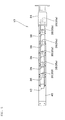
Fig. 1] Fig. 1 is a side view showing a sheet material hold-back device according an embodiment of the present invention. - [
Fig. 2] Fig. 2 is a side view showing an operation state fromFig. 1 . - [
Fig. 3] Fig. 3 is a side view showing an operation state fromFig. 2 . - [
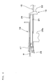
Fig. 4] Fig. 4 is a perspective view taken along a line A-A ofFig. 9 . - [
Fig. 5] Fig. 5 is a perspective view taken along a line B-B ofFig. 1 . - [
Fig. 6] Fig. 6 is an enlarged view of part C shown inFig. 2 . - [
Fig. 7] Fig. 7 is an enlarged view of part D shown inFig. 2 . - [
Fig. 8] Fig. 8 is a time chart showing an operation state of the sheet material hold-back device. - [
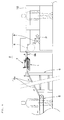
Fig. 9] Fig. 9 is a side view showing a sheet material stacking system. - [
Fig. 10] Fig. 10 is a perspective view for describing to help understand a transport state of sheet materials in the sheet material stacking system. - Embodiments of the present invention will be described hereinafter based on the drawings.
Figs. 1 to 8 show a sheet material hold-back device 1 according to one embodiment of the present invention, andFigs. 9 and10 show a sheetmaterial stacking system 2 constructed while adopting this sheet material hold-back device 1. - As shown in
Figs. 9 and10 , this sheetmaterial stacking system 2 includes a top-bottom inverter unit 6a, a sheet material hold-backunit 7, anattitude converter unit 8, and atable surface 9. Among these constituent elements, the sheet material hold-backunit 7 installs therein the sheet material hold-back device 1 according to the present invention. - The top-
bottom inverter unit 6a is a unit turns a transport state of sheet materials W into an inverse-scale state. The inverse-scale state means a transport state in which a downstream-side sheet material in a transport direction is downward in an overlap relation and an upstream-side sheet material therein is upward in the overlap relation (seeFig. 10 ).
On the upstream side (primary side) of this top-bottom inverter unit 6a, sheet materials W are transported in a scale state in which the downstream-side sheet material in the transport direction is upward and the upstream-side sheet material therein is downward in the overlap relation. The top-bottom inverter unit 6a converts this scale state into the inverse-scale state in which top and bottom of the sheet materials W are inverted (the sheet materials W are turned upside down). - The sheet material hold-back
unit 7 generates sheet material hold-back spaces along the transport direction for the sheet materials W set in the inverse-scale state at predetermined intervals. Theattitude converter unit 8 introduces the sheet materials W in a flat attitude from one end side of the sheet materials W to a downstream-side flow, converts the attitude of the sheet materials W into an upright state, and supplies the sheet materials W onto the generallyhorizontal table surface 9.
Therefore, on thistable surface 9, the sheet materials W set in the upright attitude are sequentially stacked in a state in which the sheet materials W are superimposed in a vertically aligned fashion (in a pillar-shape fallen sideways) . As stated above, the sheet materials W are turned into the inverse-scale state by being via the top-bottom inverter unit 6a. Therefore, the sheet materials W supplied onto thetable surface 9 are located on a rearmost end surface of a bunch P of stacked sheets ("stacked bunch P") that are being stacked on thetable surface 9. -
Fig. 9 shows that abinding processing unit 10 that binds a binding tie around the stacked bunch P is provided downstream-side (on a secondary side) of thetable surface 9. Theattitude converter unit 8 and thetable surface 9 as well as the bindingprocessing unit 10 depending on situations can be collectively referred to as "sheet material stacking device".
It is to be noted that aprimary conveyor 5 that horizontally feeds sheet materials W such as printed sheets (such as leaflets, which may be one sheet or a "fold section" completed by folding back a sheet) fed from a rotary press or the like is arranged upstream of this sheetmaterial stacking system 2, and asecondary conveyor 6 arranged to be subsequent to thisprimary conveyor 5 loads the sheet materials W into the system. - A transport surface of the
primary conveyor 5 is set to almost equal to a waist position of an operator since the operator carries out an operation for removing wastes (defectives) to which a printing defect, a break, a ruck or the like occurs from among the sheet materials W that are being transported or extracting samples on theprimary conveyor 5. The sheet materials W on thisprimary conveyor 5 are in the scale state.
Thesecondary conveyor 6 is provided mainly for temporarily raising the sheet materials W up to a higher position as a preliminary preparation for feeding the sheet materials W to theattitude converter unit 8. At the same time, thesecondary conveyor 6 functions to apply torsion to the sheet materials W that are being transported to turn the sheet materials W upside down. A portion that turns the sheet materials W upside down is the top-bottom inverter unit 6a. - The top-
bottom inverter unit 6a exemplarily shown inFig. 10 is designed to apply torsion to the sheet materials W while curving the transport direction leftward. Alternatively, the top-bottom inverter unit 6a can be designed to apply torsion to the sheet materials W while linearly transporting the sheet materials W (to arrange theprimary conveyor 5, thesecondary conveyor 6, and thetable surface 9 in a line). - As shown in
Figs. 1 to 7 , the sheet material hold-back device 1 includes asheet transport unit 15, a sheet material hold-back start unit 16 provided in thesheet transport unit 15, a subsequentsheet aligning unit 17 provided at an upstream position of this sheet material hold-back start unit 16, and asheet stabilizer unit 18 provided upward of this subsequentsheet aligning unit 17. - As stated above, the sheet material hold-
back device 1 according to the present embodiment is adopted as the sheet material hold-backunit 7 arranged on a higher-position route 6b directed from the top-bottom inverter unit 6a to theattitude converter unit 8 in the sheetmaterial stacking system 2. This is because the sheet materials W on this higher-position route 6b are in the inverse-scale state. Therefore, this higher-position route 6b will be described hereinafter while being referred to as "sheet transport unit 15".
As shown inFig. 4 , thesheet transport unit 15 includes a plurality of (two in an example ofFig. 5 )endless belts 19 put up in parallel with an interval formed at a center therebetween. Route width guides 20 restricting the transport direction of the sheet materials W are provided outward of a width direction of theseendless belts 19. The route width guides 20 are configured to wiggle to expand or contract in the width direction synchronously in response to driving of a width-narrowingdriving unit 21, thereby ensuring transporting the sheet materials W straight. - As shown in
Figs. 1 to 3 , the sheet material hold-back start unit 16 includes astopper 22 stopping downstream-side tip ends of the sheet materials W and astopper driving unit 23 vertically moving thisstopper 22. The sheet material hold-back start unit 16 also includes aclamp member 24 provided to operate according to movement of thestopper 22, and an ejection-promptingunit 25 provided at a location just downstream-side of thestopper 22 and theclamp member 24.
Thestopper 22 is provided between the twoendless belts 19 of thesheet transport unit 15 and below transport surfaces (surfaces supporting the sheet materials W) of theendless belts 19, and provided swingably with aswing spindle 27 provided to be orthogonal to a direction that is a horizontal direction and that is the transport direction of thesheet transport unit 15 used as a fulcrum. - The
stopper 22 swings with theswing spindle 27 used as a fulcrum, whereby a tip end portion of thestopper 22 protrudes upward of the transport surface of thesheet transport unit 15 to make it possible to stop the downstream-side tip end portion of the sheet materials W or sinks down the transport surface thereof not to cause an obstruction to transportation of the sheet materials W.
Thisstopper 22 is provided with a hook portion 28 (seeFig. 6 ) protruding to cover up the sheet materials W when the downstream-side tip end portion of the sheet materials W are stopped. That is, thishook portion 28 is provided in a state of bending toward an upstream side of thesheet transport unit 15 from the tip end portion of thestopper 22 protruding upward of the transport surface of thesheet transport unit 15. - The
stopper driving unit 23 is, for example, an air cylinder and drives thestopper 22 to swing about theswing spindle 27, thereby protruding the tip end of the stopper 22 (portion thereof on which thehook portion 28 is provided) onto the transport surface of thesheet transport unit 15 or sinking the tip end of thestopper 22 down the transport surface thereof. Alternatively, a motor driving mechanism (of a linear expansion type or a rotational operation type) can be used as thestopper driving mechanism 23 in place of the air cylinder.
Theclamp member 24 is arranged to be located right under thehook portion 28 of thestopper 22 when thisstopper 22 protrudes onto the transport surface of thesheet transport unit 15. Thisclamp member 24 is coupled to a firstsheet support base 35a of the subsequentsheet aligning unit 17 to be described later and vertically moves along (integrally) with vertical movement of this firstsheet support base 35a. - While vertical movement of the
clamp member 24 includes an upward movement and a downward movement, theclamp member 24 raises one sheet material W on thesheet transport unit 15 from below when theclamp member 24 makes an upward movement. Due to this, the raised sheet material W is clamped between theclamp member 24 and thehook portion 28 of thestopper 22 and fixed immovably simultaneously with disabling transport driving by thesheet transport unit 15.
The ejection-promptingunit 25 applies a ground pressure for grounding a sheet material W on thesheet transport unit 15 to a preceding sheet material W overlapping with the sheet material W stopped by thestopper 22 downstream-side of the stopped sheet material W. - The present embodiment shows a
rotatable pressure roller 30 that is provided above thesheet transport unit 15 and that can apply a pressing force onto a sheet material W on thesheet transport unit 15 from top down. Thepressure roller 30 is supported by aswing arm 32 vertically swingable with apivot 31 used as a fulcrum. Thepressure roller 30 is driven onto the sheet material W transported onto the sheet transport unit 15 (seeFig. 7 ) and applies a downward pressing force deriving from a self load to this sheet material W.
Alternatively, a suction unit including a suction port directing upward can be provided below thesheet transport unit 15, attracts the sheet material W on thesheet transport unit 15, and apply a downward attraction force onto the sheet material W (ground pressure for grounding the sheet material W onto the sheet transport unit 15). - The subsequent
sheet aligning unit 17 includes sheet support bases 35 and supportbase driving units 36 vertically moving the respective sheet support bases 35.
In the present embodiment, a plurality of (six in an example shown in the drawings) quadrangularly prismatic sheet support bases 35 is aligned along the transport direction of thesheet transport unit 15. That is, quadrangularly prismatic members are the respective sheet support bases 35. For sake of description, thesheet support base 35a provided at a most downstream position in the transport direction (a rightmost position inFigs. 1 to 3 ) will be referred to as "firstsheet support base 35a" followed by "secondsheet support base 35b", "thirdsheet support base 35c" ... to "sixthsheet support base 35f" in an upward direction. - As stated above, the
clamp member 24 is fixed to an upper end portion of the firstsheet support base 35a.
Furthermore, the first to sixth sheet support bases 35a to 35f are arranged so that upper end portions of adjacent sheet support bases are connected byconnection links 38, respectively, and abelt covering member 39 is covered up onto upper portions of these connection links 38. It is to be noted that at least aconnection hole 40 on one end of eachconnection link 38 is formed into an elongated hole so that the first to sixth sheet support bases 35a to 35f can vertically move independently of one another. -
Fig. 1 shows a state in which all of the first to sixth sheet support bases 35a to 35f is located downward. In these situations, connection positions at which the first to sixth sheet support bases 35a to 35f are connected to therespective connection links 38 are set so that all the connection links 38 are identical in height and horizontal, and so that upper end surfaces of the first to sixth sheet support bases 35a to 35f are flush with upper surfaces of all the connection links 38.
Needless to say, even when the first to sixth sheet support bases 35a to 35f start rising (seeFigs. 2 and3 ), the upper end surfaces thereof are flush with the upper surfaces of the connection links 38 connecting the adjacent sheet support bases as long as the adjacent sheet support bases rise together with one another. - The
belt covering member 39 is formed out of, for example, a plurality of chains coupled in a width direction, and is highly vertically flexible in a longitudinal direction but non-flexible in the width direction. A material of thebelt covering member 39 is not limited to chains but a leather or rubber belt or the like can be used as the material of thebelt covering member 39. However, the material needs to have an upper surface excellent in smoothness, slidable performance, abrasiveness and the like since thisbelt covering members 39 raises the sheet materials W using the upper surface thereof.
One end portion (right side inFig. 1 or the like in an example of the drawings) of thebelt covering member 39 is connected to theclamp member 24 provided on the upper end portion of the firstsheet support base 35a. Further, the other end portion (left side inFig. 1 or the like in the example of the drawings) of thebelt covering member 39 is held by a fixedsupport pillar 43 at a height slightly smaller than that of the transport surface of thesheet transport unit 15 and is urged by aspring 44 to be pulled obliquely downward. - Since the
belt covering member 39 is urged to be pulled by thisspring 44, thebelt covering member 39 can be feely moved and vertically moved along the transport direction while following vertical movements of the first to sixth sheet support bases 35a to 35f. Thebelt covering member 39 is thereby designed to take measures not to apply unnecessary tension to thebelt covering member 39 following the vertical movements of the first to sixth sheet support bases 35a to 35f and to be able to subsequently constantly maintain states of contact between the upper end portions ofrespective connection links 38 and those of the first to sixth sheet support bases 35a to 35f.
The supportbase driving units 36 are, for example, air cylinders or the like and disposed on afloor 45 fixed to a device frame side. The supportbase driving units 36 are provided to correspond to the first to sixth sheet support bases 35a to 35f, respectively and can vertically move directly and independently of one another. - By vertical movements of these support
base driving units 36, the upper ends of the first to sixth sheet support bases 35a to 35f (which ends correspond to the upper surface of thisbelt covering member 39 since thebelt covering member 39 is adopted in the present embodiment; in sum, the upper ends correspond to a surface supporting the sheet materials W, which applies hereafter) are moved upward to be equal to or higher than the transport surface of thesheet transport unit 15 or moved downward to be equal to or lower than the transport surface thereof. Alternatively, motor driving mechanisms (of a linear expansion type or a rotational operation type) can be adopted in place of the air cylinders as the respective supportbase driving units 36.
The supportbase driving units 36 operate to raise the first to sixth sheet support bases 35a to 35f sequentially in a staggered fashion from downstream side to upstream side of the transport direction. Timings of supporting the sheet materials W are thereby delayed sequentially from downstream side to upstream side of the transport direction. - Due to this, the sheet materials W supported by the first to sixth sheet support bases 35a to 35f float from the
sheet transport unit 15 at staggered timings, respectively. While narrowing sheet pitches by these staggered timings, the sheet materials W are turned into an aligned state in order on the first tosixth support bases 35a to 35f.
Thesheet stabilizer unit 18 includes asheet pressing member 47 and downstream-side and upstream-side elevator tools sheet pressing member 47.
In the present embodiment, it is shown that thesheet pressing member 47 is formed as a long and thin plate along the transport direction. Furthermore, a downstream end portion of thesheet pressing member 47 is bent upward at a slight angle (about 2° to 3°) . - A downstream-
side junction unit 50 is provided to be closer to a downstream side and an upstream-side junction 51 is provided to be closer to an upstream side in the transport direction on an upper surface of thesheet pressing member 47. Thesejoint units swing spindles sheet transport unit 15 used as fulcrums, respectively.
The downstream-side elevator tool 48 is, for example, an air cylinder, and disposed on alifter 55 fixed to the device frame side, with arod 48a performing an elevating operation coupled to the downstream-sidejoint unit 50 of thesheet pressing member 47 via a liftingshaft 56. - While the upstream-
side elevator tool 49 is similarly an air cylinder or the like, the upstream-side elevator tool 49 configured so that anupper cylinder 57 and alower cylinder 58 are coupled in reverse directions with respect to each other is used.
Arod 57a performing an elevating operation on theupper cylinder 57 is coupled to asupport bracket 60 provided on thelifter 55, and arod 58a performing an elevating operation on thelower cylinder 58 is coupled to the upstream-sidejoint unit 51 of thesheet pressing member 47 via a liftingshaft 61. Furthermore, aslider 62 vertically movable with thesupport bracket 60 used as a guide while being engaged with thissupport bracket 60 is provided on theupper cylinder 57. - The
upper cylinder 57 and thelower cylinder 58 vertically move in fewer elevating operation strokes than those of the downstream-side elevator tool 48. Furthermore, the elevating operation strokes of theupper cylinder 57 and thelower cylinder 58 are set so that a sum of the elevating operation strokes of the upper andlower cylinders side elevator tool 48. Moreover, one of the cylinders (upper cylinder 57 in the present embodiment) is configured to vertically move synchronously with the downstream-side elevator tool 48.
That is, when the downstream-side elevator tool 48 moves downward, theupper cylinder 57 of the upstream-side elevator tool 49 also moves downward and thesheet pressing member 47 moves downward in an inclined state in which a side held by the downstream-side elevator tool 48 in more elevating operation strokes (downstream-side end portion) of thesheet pressing member 47 is at a lower position (seeFig. 2 ). - As a result, the
sheet pressing member 47 turns into a state in which the downstream-side tip end portion (portion bent at 2° to 3°) abuts on the sheet materials W raised by the firstsheet support base 35a of the subsequentsheet aligning unit 17.
Furthermore, from this state, only thelower cylinder 58 of the upstream-side elevator tool 49 moves downward and thesheet pressing member 47 turns into a generally horizontal state at a downward position. As a result, thesheet pressing member 47 turns into a state in which almost entirety of thesheet pressing member 47 presses down the sheet materials W raised by the first to sixth sheet support bases 35a to 35f of the subsequentsheet aligning unit 17. - In this way, in the present embodiment, a timing at which the downstream-
side elevator tool 48 moves downward is set earlier than a timing at which the upstream-side elevator tool 49 (lower cylinder 58) moves downward. By so setting, thesheet pressing member 47 performs a pressing operation for pressing down a plurality of sheet materials W at subsequently staggered timings of pressing down the sheet materials W from downstream-side to upstream-side of the transport direction. -
Fig. 8 is a time chart showing an operation state of the sheet material hold-back device 1 according to the present invention. - In a state in which the
sheet transport unit 15 is transporting sheet materials W into the sheet material hold-back device 1, when a sheet material stacking system 2-side (a sensor provided in theattitude converter unit 8, thetable surface 9 or the like) transmits a signal instructing the sheet material hold-back device 1 to operate to the sheet material hold-back device 1, thestopper driving unit 23 of the sheet material hold-back start unit 16 first drives thestopper 22 to protrude onto thesheet transport unit 15. Accordingly, a sheet material W on thesheet transport unit 15 is stopped at thisstopper 22 and stopped by thisstopper 22. Thepressing roller 30 of the ejection-promptingunit 25 applies the ground pressure for grounding a sheet material W on thesheet transport unit 15 to the sheet material W (preceding sheet material W) that is not stopped by thestopper 22 and transported just in front (downstream-side) of the stopped sheet material W. - Accordingly, this preceding sheet material W more strongly receives transport driving from the
sheet transport unit 15 than frictional resistance between the preceding sheet material W and the sheet material W stopped by thestopper 22 and it is ensured that this preceding sheet material W is fed out from the sheet material hold-back device 1 (fed out to the attitude converter unit 8). That is, from this point on, sheet material hold-back spaces start to be formed.
Next, the supportbase driving units 36 of the subsequentsheet aligning unit 17 start predetermined operation to initially raise the firstsheet support base 35a. Since theclamp member 24 rises together with rising of the firstsheet support base 35a, the sheet material W stopped by thestopper 22 is raised up by theclamp member 24 and floats in a state in which the stopped sheet material W does not receive transport driving from thesheet transport unit 15. - At the same time, this sheet material W is clamped between the
hook portion 28 of thestopper 22 and theclamp member 24, thereby ensuring a transport stop state of the sheet material W without positional deviation or the like.
Furthermore, when the firstsheet support base 35a and theclamp member 24 rise, the downstream-side elevator tool 48 moves downward at the same timing of rising of the firstsheet support base 35a and theclamp member 24 in thesheet stabilizer unit 18. At the same time, theupper cylinder 57 of the upstream-side elevator tool 49 moves downward. As a result, thesheet pressing member 47 moves downward to turn into the inclined state in which the downstream-side end portion thereof is at the lower position and presses the sheet material W raised by the firstsheet support base 35a as shown inFig. 2 . - Thereafter, in the subsequent
sheet aligning unit 17, the second to sixth sheet support bases 35b to 35f are sequentially raised from downstream side to upstream side.
In this process, in thesheet stabilizer unit 18, thelower cylinder 58 of the upstream-side elevator tool 49 operates to move downward according to rising of the fifthsheet support base 35e to turn thesheet pressing member 47 into a generally horizontal state at the downward position. As shown inFig. 3 , thesheet pressing member 47 thereby turns into a state in which almost entirety of thesheet pressing member 47 presses down the sheet materials W raised by the first to sixth sheet support bases 35a to 35f of the subsequentsheet aligning unit 17. - As a consequence, the sheet materials W put between and held by the first to sixth sheet support bases 35a to 35f of the subsequent
sheet aligning unit 17 and thesheet pressing member 47 of thesheet stabilizer unit 18 stop to be transported while being aligned in order at certain pitches due to timing deviations generated in holding timings.
At a next timing after the sixthsheet support base 35f rises, thestopper 22 is caused to sink down the transport surface of thesheet transport unit 15, the first to sixth sheet support bases 35a to 35f are simultaneously moved downward, and the downstream-side elevator tool 48 and the upstream-side elevator tool 49 (upper cylinder 57 and lower cylinder 58) of thesheet stabilizer unit 18 are further raised simultaneously. - By doing so, the sheet materials W are returned onto the
sheet transport unit 15 and restart to be transported. Accordingly, the sheet materials W are fed onto the table surface for stacking while being aligned in order and stacking operation is performed without disturbance. As a result, it is possible to ensure forming sheet material hold-back spaces each having a predetermined length. - As obvious from what has been described in detail so far, the sheet material hold-
back device 1 according to the present invention forms sheet material hold-back spaces with respect to sheet materials W in the scale state. Therefore, the sheet material hold-back spaces can arrive onto the table surface 9 (seeFigs. 9 and10 ) for stacking right after formation, making it possible to ensure a short transport distance. - Therefore, it is possible to solve the problems such as occurrence of irregularity of the sheet material hold-back spaces in longer and shorter side directions and that of positional deviation in the transport direction and turns (such as curls or folding rucks) to the sheet materials W located in front of and in rear of each sheet material hold-back space.
Meanwhile, the present invention is not limited to the above-stated embodiment but can be appropriately changed according to embodiments.
For example, in the subsequentsheet aligning unit 17, the number of disposed sheet support bases 35 is not limited to a specific number. Furthermore, it is possible to dispense with thebelt covering member 39. - The manner of carrying out the sheet material hold-
back device 1 according to the present invention is not limited to that as the sheet material hold-backunit 7 of the sheetmaterial stacking system 2. - The present invention is applicable to a stacking system for printed sheets printed by a rotary press.
-
- 1
- Sheet material hold-back device
- 6a
- Top-bottom inverter unit
- 7
- Sheet material hold-back unit
- 8
- Attitude converter unit
- 9
- Table surface
- 15
- Sheet transport unit
- 16
- Sheet material hold-back start unit
- 17
- Subsequent sheet aligning unit
- 18
- Sheet stabilizer unit
- 22
- Stopper
- 24
- Clamp member
- 25
- Ejection-prompting unit
- 28
- Hook portion
- 35
- Sheet support base
- 35a
- to 35f First to sixth sheet support bases
- 47
- Sheet pressing member
- 48
- Downstream-side elevator tool
- 49
- Upstream-side elevator tool
- 50
- Downstream-side joint unit
- 51
- Upstream-side joint unit
- W
- Sheet material
Claims (20)
- A sheet material hold-back device comprising:a sheet transport unit (15) transporting a sheet material (W) in an inverse-scale state in which a downstream side in a transport direction is downward and an upstream side in the transport direction is upward in an overlap relation;a sheet material hold-back start unit (16) causing a stopper (22) stopping a downstream-side tip end portion of the sheet material (W) to protrude onto a transport surface of said sheet transport unit (15) or to sink down the transport surface; anda subsequent sheet aligning unit (17) provided at an upstream position of the sheet material hold-back start unit (16), and raising a sheet support base (35) supporting the sheet material (W) to be equal to or higher than the transport surface of the sheet transport unit (15) or lowering the sheet support base (35) to be equal to or lower than the transport surface of the sheet transport unit (15).
- The sheet material hold-back device according to claim 1, wherein
in said sheet material hold-back start unit (16), the stopper (22) is provided with a hook portion (28) protruding to cover up upward of the sheet material (W) in a state of stopping the downstream-side tip end portion of the sheet material (W), and is provided with a clamp member (24) to be vertically movable, the clamp member (24) raising the sheet material (W) from below toward this hook portion (28) and turning the sheet material (W) into a clamp state. - The sheet material hold-back device according to claim 2, wherein
said clamp member (24) is made to be vertically movable together with the sheet support base (35) of the subsequent sheet aligning unit (17) by being connected to the sheet support base (35). - The sheet material hold-back device according to claim 1, wherein
said sheet material hold-back start unit (16) is provided with an ejection-prompting unit (25) applying a ground pressure to a preceding sheet material (W) in the overlap relation downstream-side of the sheet material (W) stopped by the stopper (22) by pressing from top down or attraction from below, the ground pressure being for grounding the preceding sheet material (W) on the sheet transport unit (15). - The sheet material hold-back device according to claim 1, wherein
said subsequent sheet aligning unit (17) causes the sheet support base (35) to move upward so as to reach a plurality of sheet materials (W) while sequentially delaying timings of supporting the sheet materials (W) from the downstream side to the upstream side in the transport direction. - The sheet material hold-back device according to claim 5, wherein
said subsequent sheet aligning unit (17) includes a plurality of sheet support bases (35a to 35f) arranged along the transport direction, and the sheet support bases (35a to 35f) are movable upward while sequentially delaying these sheet support bases (35a to 35f) from the downstream side to the upstream side. - The sheet material hold-back device according to claim 1, wherein
a sheet stabilizer unit (18) is provided upward of said subsequent sheet aligning unit (17), the sheet stabilizer unit (18) presses down a sheet pressing member (47) toward an upper surface of the sheet material (W) raised by the sheet support base (35) or raising and separating the sheet pressing member (47). - The sheet material hold-back device according to claim 7, wherein
said sheet stabilizer unit (18) causes the sheet pressing member (47) to perform a pressing operation so as to reach a plurality of sheet materials (W) while sequentially delaying timings of pressing down the sheet materials (W) from the downstream side to the upstream side in the transport direction. - The sheet material hold-back device according to claim 8, wherein
in said sheet stabilizer unit (18), the sheet pressing member (47) is formed into a form long along the transport direction, a downstream side of this sheet pressing member (47) in the transport direction is held by a downstream-side elevator tool (48) via a downstream-side junction unit (50), an upstream side of this sheet pressing member (47) in the transport direction is held by an upstream-side elevator tool (49) via an upstream-side junction unit (51), and the timings at which the sheet pressing member (47) presses down the sheet materials (W) are delayed from the downstream side to the upstream side by causing the downstream-side elevator tool (48) to move downward earlier and the upstream-side elevator tool (49) to move downward later than the downstream-side elevator tool (48). - A sheet material hold-back device comprising:a sheet transport unit (15) transporting a sheet material (W) in an inverse-scale state in which a downstream side in a transport direction is downward and an upstream side in the transport direction is upward in an overlap relation;a sheet material hold-back start unit (16) causing a stopper (22) stopping a downstream-side tip end portion of the sheet material (W) to protrude onto a transport surface of said sheet transport unit (15) or to sink down the transport surface; anda subsequent sheet aligning unit (17) provided at an upstream position of the sheet material hold-back start unit (16), and raising a sheet support base (35) supporting the sheet material (W) to be equal to or higher than the transport surface of the sheet transport unit (15) or lowering the sheet support base (35) to be equal to or lower than the transport surface of the sheet transport unit (15), whereinin said sheet material hold-back start unit (16), the stopper (22) is provided with a hook portion (28) protruding to cover up upward of the sheet material (W) in a state of stopping the downstream-side tip end portion of the sheet material (W), and is provided with a clamp member (24) to be vertically movable, the clamp member (24) raising the sheet material (W) from below toward this hook portion (28) and turning the sheet material (W) into a clamp state,said clamp member (24) is made to be vertically movable together with the sheet support base (35) of the subsequent sheet aligning unit (17) by being connected to the sheet support base (35),said sheet material hold-back start unit (16) is provided with an ejection-prompting unit (25) applying a ground pressure to a preceding sheet material (W) in the overlap relation downstream-side of the sheet material (W) stopped by the stopper (22) by pressing from top down or attraction from below, the ground pressure being for grounding the preceding sheet material (W) on the sheet transport unit (15),said subsequent sheet aligning unit (17) is configured to cause the sheet support base (35) to move upward so as to reach a plurality of sheet materials (W) while sequentially delaying timings of supporting the sheet materials (W) from the downstream side to the upstream side in the transport direction,said subsequent sheet aligning unit (17) further includes a plurality of sheet support bases (35a to 35f) arranged along the transport direction, and the sheet support bases (35a to 35f) are movable upward while sequentially delaying these sheet support bases (35a to 35f) from the downstream side to the upstream side,a sheet stabilizer unit (18) is provided upward of said subsequent sheet aligning unit (17), the sheet stabilizer unit (18) presses down a sheet pressing member (47) toward an upper surface of the sheet material (W) raised by the sheet support base (35) or raising and separating the sheet pressing member (47),said sheet stabilizer unit (18) is configured to cause the sheet pressing member (47) to perform a pressing operation so as to reach a plurality of sheet materials (W) while sequentially delaying timings of pressing down the sheet materials (W) from the downstream side to the upstream side in the transport direction, andbesides, in said sheet stabilizer unit (18), the sheet pressing member (47) is formed into a form long along the transport direction, a downstream side of this sheet pressing member (47) in the transport direction is held by a downstream-side elevator tool (48) via a downstream-side junction unit (50), an upstream side of this sheet pressing member (47) in the transport direction is held by an upstream-side elevator tool (49) via an upstream-side junction unit (51), and the sheet pressing member (47) is configured so that the timings at which the sheet pressing member (47) presses down the sheet materials (W) are delayed from the downstream side to the upstream side by causing the downstream-side elevator tool (48) to move downward earlier and the upstream-side elevator tool (49) to move downward later than the downstream-side elevator tool (48).
- A sheet material stacking system comprising:a top-bottom inverter unit (6a) turning a sheet material (W) that is being transported in a scale state in which a downstream side in a transport direction is upward in an overlap relation and an upstream side is downward in the overlap relation upside down, thereby inverting the scale state of the sheet material (W) into an inverse-scale state in which the downstream side in the transport direction is downward in the overlap relation and the upstream side in the transport direction is upward in the overlap relation;a sheet material hold-back unit (7) generating sheet material hold-back spaces along the transport direction with respect to the sheet material (W) turned into the inverse-scale state by this top-bottom inverter unit (6a) at predetermined intervals;an attitude converter unit (8) introducing the sheet material (W) passed through this sheet material hold-back unit (7) to a downward flow from one end side of the sheet material (W), and converting an attitude of the sheet material (W) into an upright attitude; anda table surface (9) waiting for the sheet material (W) at a lower position of this attitude converter unit (8), and stacking sheet materials (W) sequentially in order of arrival in a tandem state while supporting the sheet materials (W) in a standing attitude, whereina sheet material hold-back device (1) according to claim 1 is disposed in said sheet material hold-back unit (7).
- A sheet material stacking system comprising:a top-bottom inverter unit (6a) turning a sheet material (W) that is being transported in a scale state in which a downstream side in a transport direction is upward in an overlap relation and an upstream side is downward in the overlap relation upside down, thereby inverting the scale state of the sheet material (W) into an inverse-scale state in which the downstream side in the transport direction is downward and the upstream side in the transport direction is upward in the overlap relation;a sheet material hold-back unit (7) generating sheet material hold-back spaces along the transport direction with respect to the sheet material (W) turned into the inverse-scale state by this top-bottom inverter unit (6a) at predetermined intervals;an attitude converter unit (8) introducing the sheet material (W) passed through this sheet material hold-back unit (7) to a downward flow from one end side of the sheet material (W), and converting an attitude of the sheet material (W) into an upright attitude; anda table surface (9) waiting for the sheet material (W) at a lower position of this attitude converter unit (8), and stacking sheet materials (W) sequentially in order of arrival in a tandem state while supporting the sheet materials (W) in a standing attitude, whereina sheet material hold-back device (1) according to claim 2 is disposed in said sheet material hold-back unit (7).
- A sheet material stacking system comprising:a top-bottom inverter unit (6a) turning a sheet material (W) that is being transported in a scale state in which a downstream side in a transport direction is upward in an overlap relation and an upstream side is downward in the overlap relation upside down, thereby inverting the scale state of the sheet material (W) into an inverse-scale state in which the downstream side in the transport direction is downward in the overlap relation and the upstream side in the transport direction is upward in the overlap relation;a sheet material hold-back unit (7) generating sheet material hold-back spaces along the transport direction with respect to the sheet material (W) turned into the inverse-scale state by this top-bottom inverter unit (6a) at predetermined intervals;an attitude converter unit (8) introducing the sheet material (W) passed through this sheet material hold-back unit (7) to a downward flow from one end side of the sheet material (W), and converting an attitude of the sheet material (W) into an upright attitude; anda table surface (9) waiting for the sheet material (W) at a lower position of this attitude converter unit (8), and stacking sheet materials (W) sequentially in order of arrival in a tandem state while supporting the sheet materials (W) in a standing attitude, whereina sheet material hold-back device (1) according to claim 3 is disposed in said sheet material hold-back unit (7).
- A sheet material stacking system comprising:a top-bottom inverter unit (6a) turning a sheet material (W) that is being transported in a scale state in which a downstream side in a transport direction is upward in an overlap relation and an upstream side is downward in the overlap relation upside down, thereby inverting the scale state of the sheet material (W) into an inverse-scale state in which the downstream side in the transport direction is downward in the overlap relation and the upstream side in the transport direction is upward in the overlap relation;a sheet material hold-back unit (7) generating sheet material hold-back spaces along the transport direction with respect to the sheet material (W) turned into the inverse-scale state by this top-bottom inverter unit (6a) at predetermined intervals;an attitude converter unit (8) introducing the sheet material (W) passed through this sheet material hold-back unit (7) to a downward flow from one end side of the sheet material (W), and converting an attitude of the sheet material (W) into an upright attitude; anda table surface (9) waiting for the sheet material (W) at a lower position of this attitude converter unit (8), and stacking sheet materials (W) sequentially in order of arrival in a tandem state while supporting the sheet materials (W) in a standing attitude, whereina sheet material hold-back device (1) according to claim 4 is disposed in said sheet material hold-back unit (7).
- A sheet material stacking system comprising:a top-bottom inverter unit (6a) turning a sheet material (W) that is being transported in a scale state in which a downstream side in a transport direction is upward in an overlap relation and an upstream side is downward in the overlap relation upside down, thereby inverting the scale state of the sheet material (W) into an inverse-scale state in which the downstream side in the transport direction is downward in the overlap relation and the upstream side in the transport direction is upward in the overlap relation;a sheet material hold-back unit (7) generating sheet material hold-back spaces along the transport direction with respect to the sheet material (W) turned into the inverse-scale state by this top-bottom inverter unit (6a) at predetermined intervals;an attitude converter unit (8) introducing the sheet material (W) passed through this sheet material hold-back unit (7) to a downward flow from one end side of the sheet material (W), and converting an attitude of the sheet material (W) into an upright attitude; anda table surface (9) waiting for the sheet material (W) at a lower position of this attitude converter unit (8), and stacking sheet materials (W) sequentially in order of arrival in a tandem state while supporting the sheet materials (W) in a standing attitude, whereina sheet material hold-back device (1) according to claim 5 is disposed in said sheet material hold-back unit (7).
- A sheet material stacking system comprising:a top-bottom inverter unit (6a) turning a sheet material (W) that is being transported in a scale state in which a downstream side in a transport direction is upward in an overlap relation and an upstream side is downward in the overlap relation upside down, thereby inverting the scale state of the sheet material (W) into an inverse-scale state in which the downstream side in the transport direction is downward in the overlap relation and the upstream side in the transport direction is upward in the overlap relation;a sheet material hold-back unit (7) generating sheet material hold-back spaces along the transport direction with respect to the sheet material (W) turned into the inverse-scale state by this top-bottom inverter unit (6a) at predetermined intervals;an attitude converter unit (8) introducing the sheet material (W) passed through this sheet material hold-back unit (7) to a downward flow from one end side of the sheet material (W), and converting an attitude of the sheet material (W) into an upright attitude; anda table surface (9) waiting for the sheet material (W) at a lower position of this attitude converter unit (8), and stacking sheet materials (W) sequentially in order of arrival in a tandem state while supporting the sheet materials (W) in a standing attitude, whereina sheet material hold-back device (1) according to claim 6 is disposed in said sheet material hold-back unit (7).
- A sheet material stacking system comprising:a top-bottom inverter unit (6a) turning a sheet material (W) that is being transported in a scale state in which a downstream side in a transport direction is upward in an overlap relation and an upstream side is downward in the overlap relation upside down, thereby inverting the scale state of the sheet material (W) into an inverse-scale state in which the downstream side in the transport direction is downward in the overlap relation and the upstream side in the transport direction is upward in the overlap relation;a sheet material hold-back unit (7) generating sheet material hold-back spaces along the transport direction with respect to the sheet material (W) turned into the inverse-scale state by this top-bottom inverter unit (6a) at predetermined intervals;an attitude converter unit (8) introducing the sheet material (W) passed through this sheet material hold-back unit (7) to a downward flow from one end side of the sheet material (W), and converting an attitude of the sheet material (W) into an upright attitude; anda table surface (9) waiting for the sheet material (W) at a lower position of this attitude converter unit (8), and stacking sheet materials (W) sequentially in order of arrival in a tandem state while supporting the sheet materials (W) in a standing attitude, whereina sheet material hold-back device (1) according to claim 7 is disposed in said sheet material hold-back unit (7).
- A sheet material stacking system comprising:a top-bottom inverter unit (6a) turning a sheet material (W) that is being transported in a scale state in which a downstream side in a transport direction is upward in an overlap relation and an upstream side is downward in the overlap relation upside down, thereby inverting the scale state of the sheet material (W) into an inverse-scale state in which the downstream side in the transport direction is downward in the overlap relation and the upstream side in the transport direction is upward in the overlap relation;a sheet material hold-back unit (7) generating sheet material hold-back spaces along the transport direction with respect to the sheet material (W) turned into the inverse-scale state by this top-bottom inverter unit (6a) at predetermined intervals;an attitude converter unit (8) introducing the sheet material (W) passed through this sheet material hold-back unit (7) to a downward flow from one end side of the sheet material (W), and converting an attitude of the sheet material (W) into an upright attitude; anda table surface (9) waiting for the sheet material (W) at a lower position of this attitude converter unit (8), and stacking sheet materials (W) sequentially in order of arrival in a tandem state while supporting the sheet materials (W) in a standing attitude, whereina sheet material hold-back device (1) according to claim 8 is disposed in said sheet material hold-back unit (7).
- A sheet material stacking system comprising:a top-bottom inverter unit (6a) turning a sheet material (W) that is being transported in a scale state in which a downstream side in a transport direction is upward in an overlap relation and an upstream side is downward in the overlap relation upside down, thereby inverting the scale state of the sheet material (W) into an inverse-scale state in which the downstream side in the transport direction is downward in the overlap relation and the upstream side in the transport direction is upward in the overlap relation;a sheet material hold-back unit (7) generating sheet material hold-back spaces along the transport direction with respect to the sheet material (W) turned into the inverse-scale state by this top-bottom inverter unit (6a) at predetermined intervals;an attitude converter unit (8) introducing the sheet material (W) passed through this sheet material hold-back unit (7) to a downward flow from one end side of the sheet material (W), and converting an attitude of the sheet material (W) into an upright attitude; anda table surface (9) waiting for the sheet material (W) at a lower position of this attitude converter unit (8), and stacking sheet materials (W) sequentially in order of arrival in a tandem state while supporting the sheet materials (W) in a standing attitude, whereina sheet material hold-back device (1) according to claim 9 is disposed in said sheet material hold-back unit (7).
- A sheet material stacking system comprising:a top-bottom inverter unit (6a) turning a sheet material (W) that is being transported in a scale state in which a downstream side in a transport direction is upward in an overlap relation and an upstream side is downward in the overlap relation upside down, thereby inverting the scale state of the sheet material (W) into an inverse-scale state in which the downstream side in the transport direction is downward in the overlap relation and the upstream side in the transport direction is upward in the overlap relation;a sheet material hold-back unit (7) generating sheet material hold-back spaces along the transport direction with respect to the sheet material (W) turned into the inverse-scale state by this top-bottom inverter unit (6a) at predetermined intervals;an attitude converter unit (8) introducing the sheet material (W) passed through this sheet material hold-back unit (7) to a downward flow from one end side of the sheet material (W), and converting an attitude of the sheet material (W) into an upright attitude; anda table surface (9) waiting for the sheet material (W) at a lower position of this attitude converter unit (8), and stacking sheet materials (W) sequentially in order of arrival in a tandem state while supporting the sheet materials (W) in a standing attitude, whereina sheet material hold-back device (1) according to claim 10 is disposed in said sheet material hold-back unit (7).
Applications Claiming Priority (2)
| Application Number | Priority Date | Filing Date | Title |
|---|---|---|---|
| JP2008221861A JP5122404B2 (en) | 2008-08-29 | 2008-08-29 | Seiko device and sheet material accumulation system |
| PCT/JP2009/063252 WO2010024072A1 (en) | 2008-08-29 | 2009-07-24 | Sheet hold back device and sheet stacking system |
Publications (3)
| Publication Number | Publication Date |
|---|---|
| EP2319786A1 true EP2319786A1 (en) | 2011-05-11 |
| EP2319786A4 EP2319786A4 (en) | 2012-03-14 |
| EP2319786B1 EP2319786B1 (en) | 2013-04-17 |
Family
ID=41721245
Family Applications (1)
| Application Number | Title | Priority Date | Filing Date |
|---|---|---|---|
| EP09809727.2A Not-in-force EP2319786B1 (en) | 2008-08-29 | 2009-07-24 | Sheet hold back device and sheet stacking system |
Country Status (4)
| Country | Link |
|---|---|
| EP (1) | EP2319786B1 (en) |
| JP (1) | JP5122404B2 (en) |
| CN (1) | CN102137805B (en) |
| WO (1) | WO2010024072A1 (en) |
Families Citing this family (4)
| Publication number | Priority date | Publication date | Assignee | Title |
|---|---|---|---|---|
| CN103480994B (en) * | 2013-09-29 | 2015-12-09 | 徐夏秋 | Full-automatic heat exchange plate bonding machine |
| CN110039794B (en) * | 2019-05-10 | 2023-12-05 | 广州明森科技股份有限公司 | A dual-station sheet material laminating device and method |
| CN118848280B (en) * | 2024-08-29 | 2025-07-04 | 广东铭鑫机电装配科技有限公司 | Laser cutting device and method for thin metal sheet |
| CN120921602B (en) * | 2025-10-16 | 2026-01-23 | 万向钱潮股份公司 | A method and system for cooling rubber sheets |
Family Cites Families (13)
| Publication number | Priority date | Publication date | Assignee | Title |
|---|---|---|---|---|
| DE1085409B (en) * | 1957-05-16 | 1960-07-14 | Holweg Const Mec | Device for dispensing, counting and stacking bags into packages and for bundling the stacks of packages |
| BE750684A (en) * | 1970-05-20 | 1970-11-03 | Jager Louis Hermann | DEVICE FOR AMASSING, COUNTING AND STACKING FLAT OBJECTS BROUGHT ONE BY ONE TO THIS DEVICE. |
| US3659699A (en) * | 1970-07-17 | 1972-05-02 | Graphic Engineers Inc | Conveyor mechanism |
| JPS6083895A (en) | 1983-10-14 | 1985-05-13 | 共同印刷株式会社 | Stacker conveyor device with book setting device |
| JP2552490B2 (en) * | 1987-06-15 | 1996-11-13 | 英機 福崎 | Single sheet overlap device |
| JP2729849B2 (en) * | 1990-04-13 | 1998-03-18 | ニチロ工業株式会社 | Printing book cutting device |
| JPH085179A (en) | 1994-06-22 | 1996-01-12 | Toshiba Corp | Stirling refrigerator |
| JP2000118511A (en) | 1998-08-13 | 2000-04-25 | Gunze Ltd | Printing sheet binder |
| JP3586572B2 (en) * | 1998-10-23 | 2004-11-10 | 三菱重工業株式会社 | Sheet feeder |
| JP2001287851A (en) * | 2000-04-04 | 2001-10-16 | Gunze Ltd | Cutting device for sheet |
| JP2006199467A (en) * | 2005-01-21 | 2006-08-03 | Gunze Ltd | Temporarily stopping device for sheet being carried |
| JP4757869B2 (en) * | 2005-04-28 | 2011-08-24 | グンゼ株式会社 | Sheet material conveying apparatus and bookbinding apparatus |
| CN2851198Y (en) * | 2005-09-12 | 2006-12-27 | 上海印钞厂 | Paper sheet expanding device |
-
2008
- 2008-08-29 JP JP2008221861A patent/JP5122404B2/en active Active
-
2009
- 2009-07-24 WO PCT/JP2009/063252 patent/WO2010024072A1/en not_active Ceased
- 2009-07-24 EP EP09809727.2A patent/EP2319786B1/en not_active Not-in-force
- 2009-07-24 CN CN2009801338224A patent/CN102137805B/en not_active Expired - Fee Related
Also Published As
| Publication number | Publication date |
|---|---|
| JP5122404B2 (en) | 2013-01-16 |
| JP2010052929A (en) | 2010-03-11 |
| EP2319786A4 (en) | 2012-03-14 |
| WO2010024072A1 (en) | 2010-03-04 |
| CN102137805A (en) | 2011-07-27 |
| EP2319786B1 (en) | 2013-04-17 |
| CN102137805B (en) | 2013-12-04 |
Similar Documents
| Publication | Publication Date | Title |
|---|---|---|
| KR101144328B1 (en) | Automatic tape attaching apparatus | |
| US20090238672A1 (en) | Infeed station of a stack palletizing system and method for transferring stacks to a gripper with an infeed station of this type | |
| EP2319786B1 (en) | Sheet hold back device and sheet stacking system | |
| AU2007209736A2 (en) | Apparatus for collating flat objects and for conveying the collated objects further | |
| CN104981420A (en) | A printer paper supply device | |
| JP2006124171A (en) | Paper post-processing device | |
| JPH0834079A (en) | Carton aligning and feeding device | |
| KR102313204B1 (en) | Automatic banding device for the packing box of the Box making machine | |
| CN217295178U (en) | Booklet paging device | |
| KR101777393B1 (en) | Aluminum plate cutting apparatus | |
| CN114537804B (en) | Booklet paging device and method | |
| JP5821915B2 (en) | Paper processing apparatus and image forming system | |
| CN101218160B (en) | Sheet stacking device | |
| US7431277B2 (en) | Device for collecting printed sheets in a certain sequence astride and atop one another to form a printed product | |
| JPH10279080A (en) | Stacker of unbound stacked sheets | |
| JP2006124173A (en) | Paper post-processing device | |
| KR200378286Y1 (en) | Device for sorting and piling plate | |
| ITTO20090300A1 (en) | DEVICE FOR FEEDING SHEETS. | |
| JP2008156075A (en) | Paper feed device | |
| JP7432473B2 (en) | Transfer device | |
| CN110104282B (en) | Anti-pedal clamp and anti-pedal mounting equipment | |
| WO2006117930A1 (en) | Sheet material carrying device and printed sheet stacking device | |
| JP7333074B2 (en) | Folding supply device and alignment method | |
| JPH07157119A (en) | Signature feeder | |
| JP2014214016A (en) | Sheet storage device, and post-processor and image forming system using the same |
Legal Events
| Date | Code | Title | Description |
|---|---|---|---|
| PUAI | Public reference made under article 153(3) epc to a published international application that has entered the european phase |
Free format text: ORIGINAL CODE: 0009012 |
|
| 17P | Request for examination filed |
Effective date: 20110224 |
|
| AK | Designated contracting states |
Kind code of ref document: A1 Designated state(s): AT BE BG CH CY CZ DE DK EE ES FI FR GB GR HR HU IE IS IT LI LT LU LV MC MK MT NL NO PL PT RO SE SI SK SM TR |
|
| AX | Request for extension of the european patent |
Extension state: AL BA RS |
|
| DAX | Request for extension of the european patent (deleted) | ||
| A4 | Supplementary search report drawn up and despatched |
Effective date: 20120214 |
|
| RIC1 | Information provided on ipc code assigned before grant |
Ipc: B65H 33/12 20060101ALI20120208BHEP Ipc: B65H 5/24 20060101AFI20120208BHEP Ipc: B65G 47/88 20060101ALI20120208BHEP Ipc: B65H 29/66 20060101ALI20120208BHEP |
|
| REG | Reference to a national code |
Ref country code: DE Ref legal event code: R079 Ref document number: 602009015084 Country of ref document: DE Free format text: PREVIOUS MAIN CLASS: B65H0005240000 Ipc: B65H0029660000 |
|
| GRAP | Despatch of communication of intention to grant a patent |
Free format text: ORIGINAL CODE: EPIDOSNIGR1 |
|
| RIC1 | Information provided on ipc code assigned before grant |
Ipc: B65H 29/66 20060101AFI20121123BHEP Ipc: B65H 33/12 20060101ALI20121123BHEP |
|
| GRAS | Grant fee paid |
Free format text: ORIGINAL CODE: EPIDOSNIGR3 |
|
| GRAA | (expected) grant |
Free format text: ORIGINAL CODE: 0009210 |
|
| AK | Designated contracting states |
Kind code of ref document: B1 Designated state(s): AT BE BG CH CY CZ DE DK EE ES FI FR GB GR HR HU IE IS IT LI LT LU LV MC MK MT NL NO PL PT RO SE SI SK SM TR |
|
| REG | Reference to a national code |
Ref country code: GB Ref legal event code: FG4D |
|
| REG | Reference to a national code |
Ref country code: CH Ref legal event code: EP |
|
| REG | Reference to a national code |
Ref country code: IE Ref legal event code: FG4D |
|
| REG | Reference to a national code |
Ref country code: AT Ref legal event code: REF Ref document number: 607153 Country of ref document: AT Kind code of ref document: T Effective date: 20130515 |
|
| REG | Reference to a national code |
Ref country code: DE Ref legal event code: R096 Ref document number: 602009015084 Country of ref document: DE Effective date: 20130613 |
|
| REG | Reference to a national code |
Ref country code: AT Ref legal event code: MK05 Ref document number: 607153 Country of ref document: AT Kind code of ref document: T Effective date: 20130417 |
|
| REG | Reference to a national code |
Ref country code: LT Ref legal event code: MG4D |
|
| REG | Reference to a national code |
Ref country code: NL Ref legal event code: VDEP Effective date: 20130417 |
|
| PG25 | Lapsed in a contracting state [announced via postgrant information from national office to epo] |
Ref country code: PT Free format text: LAPSE BECAUSE OF FAILURE TO SUBMIT A TRANSLATION OF THE DESCRIPTION OR TO PAY THE FEE WITHIN THE PRESCRIBED TIME-LIMIT Effective date: 20130819 Ref country code: SI Free format text: LAPSE BECAUSE OF FAILURE TO SUBMIT A TRANSLATION OF THE DESCRIPTION OR TO PAY THE FEE WITHIN THE PRESCRIBED TIME-LIMIT Effective date: 20130417 Ref country code: BE Free format text: LAPSE BECAUSE OF FAILURE TO SUBMIT A TRANSLATION OF THE DESCRIPTION OR TO PAY THE FEE WITHIN THE PRESCRIBED TIME-LIMIT Effective date: 20130417 Ref country code: NO Free format text: LAPSE BECAUSE OF FAILURE TO SUBMIT A TRANSLATION OF THE DESCRIPTION OR TO PAY THE FEE WITHIN THE PRESCRIBED TIME-LIMIT Effective date: 20130717 Ref country code: SE Free format text: LAPSE BECAUSE OF FAILURE TO SUBMIT A TRANSLATION OF THE DESCRIPTION OR TO PAY THE FEE WITHIN THE PRESCRIBED TIME-LIMIT Effective date: 20130417 Ref country code: AT Free format text: LAPSE BECAUSE OF FAILURE TO SUBMIT A TRANSLATION OF THE DESCRIPTION OR TO PAY THE FEE WITHIN THE PRESCRIBED TIME-LIMIT Effective date: 20130417 Ref country code: FI Free format text: LAPSE BECAUSE OF FAILURE TO SUBMIT A TRANSLATION OF THE DESCRIPTION OR TO PAY THE FEE WITHIN THE PRESCRIBED TIME-LIMIT Effective date: 20130417 Ref country code: GR Free format text: LAPSE BECAUSE OF FAILURE TO SUBMIT A TRANSLATION OF THE DESCRIPTION OR TO PAY THE FEE WITHIN THE PRESCRIBED TIME-LIMIT Effective date: 20130718 Ref country code: LT Free format text: LAPSE BECAUSE OF FAILURE TO SUBMIT A TRANSLATION OF THE DESCRIPTION OR TO PAY THE FEE WITHIN THE PRESCRIBED TIME-LIMIT Effective date: 20130417 Ref country code: ES Free format text: LAPSE BECAUSE OF FAILURE TO SUBMIT A TRANSLATION OF THE DESCRIPTION OR TO PAY THE FEE WITHIN THE PRESCRIBED TIME-LIMIT Effective date: 20130728 Ref country code: IS Free format text: LAPSE BECAUSE OF FAILURE TO SUBMIT A TRANSLATION OF THE DESCRIPTION OR TO PAY THE FEE WITHIN THE PRESCRIBED TIME-LIMIT Effective date: 20130817 |
|
| PG25 | Lapsed in a contracting state [announced via postgrant information from national office to epo] |
Ref country code: CY Free format text: LAPSE BECAUSE OF FAILURE TO SUBMIT A TRANSLATION OF THE DESCRIPTION OR TO PAY THE FEE WITHIN THE PRESCRIBED TIME-LIMIT Effective date: 20130417 Ref country code: BG Free format text: LAPSE BECAUSE OF FAILURE TO SUBMIT A TRANSLATION OF THE DESCRIPTION OR TO PAY THE FEE WITHIN THE PRESCRIBED TIME-LIMIT Effective date: 20130717 Ref country code: LV Free format text: LAPSE BECAUSE OF FAILURE TO SUBMIT A TRANSLATION OF THE DESCRIPTION OR TO PAY THE FEE WITHIN THE PRESCRIBED TIME-LIMIT Effective date: 20130417 Ref country code: HR Free format text: LAPSE BECAUSE OF FAILURE TO SUBMIT A TRANSLATION OF THE DESCRIPTION OR TO PAY THE FEE WITHIN THE PRESCRIBED TIME-LIMIT Effective date: 20130417 Ref country code: PL Free format text: LAPSE BECAUSE OF FAILURE TO SUBMIT A TRANSLATION OF THE DESCRIPTION OR TO PAY THE FEE WITHIN THE PRESCRIBED TIME-LIMIT Effective date: 20130417 |
|
| PG25 | Lapsed in a contracting state [announced via postgrant information from national office to epo] |
Ref country code: SK Free format text: LAPSE BECAUSE OF FAILURE TO SUBMIT A TRANSLATION OF THE DESCRIPTION OR TO PAY THE FEE WITHIN THE PRESCRIBED TIME-LIMIT Effective date: 20130417 Ref country code: CZ Free format text: LAPSE BECAUSE OF FAILURE TO SUBMIT A TRANSLATION OF THE DESCRIPTION OR TO PAY THE FEE WITHIN THE PRESCRIBED TIME-LIMIT Effective date: 20130417 Ref country code: DK Free format text: LAPSE BECAUSE OF FAILURE TO SUBMIT A TRANSLATION OF THE DESCRIPTION OR TO PAY THE FEE WITHIN THE PRESCRIBED TIME-LIMIT Effective date: 20130417 Ref country code: EE Free format text: LAPSE BECAUSE OF FAILURE TO SUBMIT A TRANSLATION OF THE DESCRIPTION OR TO PAY THE FEE WITHIN THE PRESCRIBED TIME-LIMIT Effective date: 20130417 |
|
| PLBE | No opposition filed within time limit |
Free format text: ORIGINAL CODE: 0009261 |
|
| STAA | Information on the status of an ep patent application or granted ep patent |
Free format text: STATUS: NO OPPOSITION FILED WITHIN TIME LIMIT |
|
| PG25 | Lapsed in a contracting state [announced via postgrant information from national office to epo] |
Ref country code: NL Free format text: LAPSE BECAUSE OF FAILURE TO SUBMIT A TRANSLATION OF THE DESCRIPTION OR TO PAY THE FEE WITHIN THE PRESCRIBED TIME-LIMIT Effective date: 20130417 Ref country code: RO Free format text: LAPSE BECAUSE OF FAILURE TO SUBMIT A TRANSLATION OF THE DESCRIPTION OR TO PAY THE FEE WITHIN THE PRESCRIBED TIME-LIMIT Effective date: 20130417 Ref country code: IT Free format text: LAPSE BECAUSE OF FAILURE TO SUBMIT A TRANSLATION OF THE DESCRIPTION OR TO PAY THE FEE WITHIN THE PRESCRIBED TIME-LIMIT Effective date: 20130417 Ref country code: MC Free format text: LAPSE BECAUSE OF FAILURE TO SUBMIT A TRANSLATION OF THE DESCRIPTION OR TO PAY THE FEE WITHIN THE PRESCRIBED TIME-LIMIT Effective date: 20130417 |
|
| REG | Reference to a national code |
Ref country code: CH Ref legal event code: PL |
|
| 26N | No opposition filed |
Effective date: 20140120 |
|
| GBPC | Gb: european patent ceased through non-payment of renewal fee |
Effective date: 20130724 |
|
| REG | Reference to a national code |
Ref country code: IE Ref legal event code: MM4A |
|
| PG25 | Lapsed in a contracting state [announced via postgrant information from national office to epo] |
Ref country code: LI Free format text: LAPSE BECAUSE OF NON-PAYMENT OF DUE FEES Effective date: 20130731 Ref country code: CH Free format text: LAPSE BECAUSE OF NON-PAYMENT OF DUE FEES Effective date: 20130731 Ref country code: GB Free format text: LAPSE BECAUSE OF NON-PAYMENT OF DUE FEES Effective date: 20130724 |
|
| REG | Reference to a national code |
Ref country code: DE Ref legal event code: R097 Ref document number: 602009015084 Country of ref document: DE Effective date: 20140120 |
|
| PG25 | Lapsed in a contracting state [announced via postgrant information from national office to epo] |
Ref country code: IE Free format text: LAPSE BECAUSE OF NON-PAYMENT OF DUE FEES Effective date: 20130724 |
|
| PG25 | Lapsed in a contracting state [announced via postgrant information from national office to epo] |
Ref country code: SM Free format text: LAPSE BECAUSE OF FAILURE TO SUBMIT A TRANSLATION OF THE DESCRIPTION OR TO PAY THE FEE WITHIN THE PRESCRIBED TIME-LIMIT Effective date: 20130417 |
|
| PG25 | Lapsed in a contracting state [announced via postgrant information from national office to epo] |
Ref country code: MT Free format text: LAPSE BECAUSE OF FAILURE TO SUBMIT A TRANSLATION OF THE DESCRIPTION OR TO PAY THE FEE WITHIN THE PRESCRIBED TIME-LIMIT Effective date: 20130417 Ref country code: TR Free format text: LAPSE BECAUSE OF FAILURE TO SUBMIT A TRANSLATION OF THE DESCRIPTION OR TO PAY THE FEE WITHIN THE PRESCRIBED TIME-LIMIT Effective date: 20130417 |
|
| PG25 | Lapsed in a contracting state [announced via postgrant information from national office to epo] |
Ref country code: LU Free format text: LAPSE BECAUSE OF NON-PAYMENT OF DUE FEES Effective date: 20130724 Ref country code: HU Free format text: LAPSE BECAUSE OF FAILURE TO SUBMIT A TRANSLATION OF THE DESCRIPTION OR TO PAY THE FEE WITHIN THE PRESCRIBED TIME-LIMIT; INVALID AB INITIO Effective date: 20090724 Ref country code: MK Free format text: LAPSE BECAUSE OF FAILURE TO SUBMIT A TRANSLATION OF THE DESCRIPTION OR TO PAY THE FEE WITHIN THE PRESCRIBED TIME-LIMIT Effective date: 20130417 |
|
| REG | Reference to a national code |
Ref country code: FR Ref legal event code: PLFP Year of fee payment: 8 |
|
| REG | Reference to a national code |
Ref country code: FR Ref legal event code: PLFP Year of fee payment: 9 |
|
| REG | Reference to a national code |
Ref country code: FR Ref legal event code: PLFP Year of fee payment: 10 |
|
| PGFP | Annual fee paid to national office [announced via postgrant information from national office to epo] |
Ref country code: FR Payment date: 20180612 Year of fee payment: 10 |
|
| PGFP | Annual fee paid to national office [announced via postgrant information from national office to epo] |
Ref country code: DE Payment date: 20180710 Year of fee payment: 10 |
|
| REG | Reference to a national code |
Ref country code: DE Ref legal event code: R119 Ref document number: 602009015084 Country of ref document: DE |
|
| PG25 | Lapsed in a contracting state [announced via postgrant information from national office to epo] |
Ref country code: DE Free format text: LAPSE BECAUSE OF NON-PAYMENT OF DUE FEES Effective date: 20200201 |
|
| PG25 | Lapsed in a contracting state [announced via postgrant information from national office to epo] |
Ref country code: FR Free format text: LAPSE BECAUSE OF NON-PAYMENT OF DUE FEES Effective date: 20190731 |