EP2319375A1 - System for producing beverages by infusion - Google Patents
System for producing beverages by infusion Download PDFInfo
- Publication number
- EP2319375A1 EP2319375A1 EP10178827A EP10178827A EP2319375A1 EP 2319375 A1 EP2319375 A1 EP 2319375A1 EP 10178827 A EP10178827 A EP 10178827A EP 10178827 A EP10178827 A EP 10178827A EP 2319375 A1 EP2319375 A1 EP 2319375A1
- Authority
- EP
- European Patent Office
- Prior art keywords
- chamber
- upstream
- closure
- package
- pump
- Prior art date
- Legal status (The legal status is an assumption and is not a legal conclusion. Google has not performed a legal analysis and makes no representation as to the accuracy of the status listed.)
- Granted
Links
- 238000001802 infusion Methods 0.000 title claims abstract description 43
- 235000013361 beverage Nutrition 0.000 title claims abstract description 15
- 238000011144 upstream manufacturing Methods 0.000 claims abstract description 96
- 238000004806 packaging method and process Methods 0.000 claims abstract description 58
- 238000000034 method Methods 0.000 claims abstract description 3
- 238000004519 manufacturing process Methods 0.000 claims description 13
- 230000005611 electricity Effects 0.000 claims description 7
- 238000011084 recovery Methods 0.000 claims description 6
- 239000012530 fluid Substances 0.000 claims description 5
- 230000000007 visual effect Effects 0.000 claims description 2
- 238000012856 packing Methods 0.000 claims 1
- 230000005484 gravity Effects 0.000 abstract description 10
- 238000007789 sealing Methods 0.000 abstract description 9
- 230000003750 conditioning effect Effects 0.000 description 11
- 238000013519 translation Methods 0.000 description 8
- XLYOFNOQVPJJNP-UHFFFAOYSA-N water Substances O XLYOFNOQVPJJNP-UHFFFAOYSA-N 0.000 description 7
- 235000013353 coffee beverage Nutrition 0.000 description 6
- 230000000694 effects Effects 0.000 description 5
- 235000021183 entrée Nutrition 0.000 description 5
- 125000006850 spacer group Chemical group 0.000 description 5
- 230000007547 defect Effects 0.000 description 4
- 238000012423 maintenance Methods 0.000 description 4
- 210000000056 organ Anatomy 0.000 description 4
- 241000287107 Passer Species 0.000 description 3
- 230000006835 compression Effects 0.000 description 3
- 238000007906 compression Methods 0.000 description 3
- 238000006073 displacement reaction Methods 0.000 description 3
- 238000002360 preparation method Methods 0.000 description 3
- 238000000926 separation method Methods 0.000 description 3
- 230000007257 malfunction Effects 0.000 description 2
- 239000000463 material Substances 0.000 description 2
- 238000012546 transfer Methods 0.000 description 2
- 241001415961 Gaviidae Species 0.000 description 1
- 241001122767 Theaceae Species 0.000 description 1
- 230000006978 adaptation Effects 0.000 description 1
- XAGFODPZIPBFFR-UHFFFAOYSA-N aluminium Chemical compound [Al] XAGFODPZIPBFFR-UHFFFAOYSA-N 0.000 description 1
- 229910052782 aluminium Inorganic materials 0.000 description 1
- 238000004891 communication Methods 0.000 description 1
- 230000002860 competitive effect Effects 0.000 description 1
- 235000015114 espresso Nutrition 0.000 description 1
- 238000000605 extraction Methods 0.000 description 1
- 235000012171 hot beverage Nutrition 0.000 description 1
- 238000002347 injection Methods 0.000 description 1
- 239000007924 injection Substances 0.000 description 1
- 238000002844 melting Methods 0.000 description 1
- 230000008018 melting Effects 0.000 description 1
- 230000000284 resting effect Effects 0.000 description 1
- 229910001220 stainless steel Inorganic materials 0.000 description 1
- 239000010935 stainless steel Substances 0.000 description 1
Images


Classifications
-
- A—HUMAN NECESSITIES
- A47—FURNITURE; DOMESTIC ARTICLES OR APPLIANCES; COFFEE MILLS; SPICE MILLS; SUCTION CLEANERS IN GENERAL
- A47J—KITCHEN EQUIPMENT; COFFEE MILLS; SPICE MILLS; APPARATUS FOR MAKING BEVERAGES
- A47J31/00—Apparatus for making beverages
- A47J31/40—Beverage-making apparatus with dispensing means for adding a measured quantity of ingredients, e.g. coffee, water, sugar, cocoa, milk, tea
- A47J31/407—Beverage-making apparatus with dispensing means for adding a measured quantity of ingredients, e.g. coffee, water, sugar, cocoa, milk, tea with ingredient-containing cartridges; Cartridge-perforating means
-
- A—HUMAN NECESSITIES
- A47—FURNITURE; DOMESTIC ARTICLES OR APPLIANCES; COFFEE MILLS; SPICE MILLS; SUCTION CLEANERS IN GENERAL
- A47J—KITCHEN EQUIPMENT; COFFEE MILLS; SPICE MILLS; APPARATUS FOR MAKING BEVERAGES
- A47J31/00—Apparatus for making beverages
- A47J31/24—Coffee-making apparatus in which hot water is passed through the filter under pressure, i.e. in which the coffee grounds are extracted under pressure
- A47J31/34—Coffee-making apparatus in which hot water is passed through the filter under pressure, i.e. in which the coffee grounds are extracted under pressure with hot water under liquid pressure
- A47J31/36—Coffee-making apparatus in which hot water is passed through the filter under pressure, i.e. in which the coffee grounds are extracted under pressure with hot water under liquid pressure with mechanical pressure-producing means
- A47J31/3604—Coffee-making apparatus in which hot water is passed through the filter under pressure, i.e. in which the coffee grounds are extracted under pressure with hot water under liquid pressure with mechanical pressure-producing means with a mechanism arranged to move the brewing chamber between loading, infusing and ejecting stations
- A47J31/3623—Cartridges being employed
- A47J31/3633—Means to perform transfer from a loading position to an infusing position
-
- A—HUMAN NECESSITIES
- A47—FURNITURE; DOMESTIC ARTICLES OR APPLIANCES; COFFEE MILLS; SPICE MILLS; SUCTION CLEANERS IN GENERAL
- A47J—KITCHEN EQUIPMENT; COFFEE MILLS; SPICE MILLS; APPARATUS FOR MAKING BEVERAGES
- A47J31/00—Apparatus for making beverages
- A47J31/24—Coffee-making apparatus in which hot water is passed through the filter under pressure, i.e. in which the coffee grounds are extracted under pressure
- A47J31/34—Coffee-making apparatus in which hot water is passed through the filter under pressure, i.e. in which the coffee grounds are extracted under pressure with hot water under liquid pressure
- A47J31/36—Coffee-making apparatus in which hot water is passed through the filter under pressure, i.e. in which the coffee grounds are extracted under pressure with hot water under liquid pressure with mechanical pressure-producing means
- A47J31/3604—Coffee-making apparatus in which hot water is passed through the filter under pressure, i.e. in which the coffee grounds are extracted under pressure with hot water under liquid pressure with mechanical pressure-producing means with a mechanism arranged to move the brewing chamber between loading, infusing and ejecting stations
- A47J31/3623—Cartridges being employed
- A47J31/3638—Means to eject the cartridge after brewing
Definitions
- the present invention relates to a device for producing beverages by infusion of a product contained in a packaging.
- the document WOA9517121 proposes an automatic machine for the infusion of hot drinks comprising an infusion chamber for receiving a package, the chamber having two half-chambers arranged to be mutually distant or close together to respectively close or open the infusion chamber.
- a stirrup is also provided in the lower position of the infusion chamber so as to retain the conditioning or allow its ejection by gravity when the stop is retracted.
- a flap is provided in the upper position of the brewing chamber.
- the invention has a sequential operation. Indeed, for a given position of the upstream closure means, the downstream closure means admit only one position. Conversely, for a given position of the downstream closure means, the upstream closure means admit only one position.
- the relative positioning between the upstream positioning means on the one hand and downstream on the other hand is perfectly controlled.
- the invention improves the reliability of existing machines.
- the invention may also have the additional feature that the closure device is arranged so that the upstream closure means are integral with the downstream closure means.
- the invention thus makes it possible to significantly reduce the number of moving parts relative to one another as well as the complexity of the structure of the system.
- This structure allows a simplification of the kinematics of the organs to pass alternately from the first to the second position. The risks of locking the mechanism, the number of parts involved, the manufacturing cost and the defect rate are therefore substantially reduced.
- a closure device adapted to selectively prevent and allow access to an infusion chamber for receiving a packaging for beverage production comprising upstream closure means for selectively prevent or allow access to the chamber from upstream of the latter and downstream closure means for selectively receive the packaging in the chamber or allow the output of the packaging out of the chamber by gravity, the upstream closure means being secured to the downstream closure means.
- the closure device has the additional feature that it is intended to be moved alternately in at least one given principal direction, in that the upstream closure means and the downstream closure means are arranged in such a way as to present a mutual offset according to this given principal direction.
- Also provided according to the invention is a beverage production machine by infusion of a product contained in a package comprising a system according to any one of the preceding characteristics or a closure device according to any one of the preceding features.
- a method of producing beverage by infusing a product contained in a package using a system according to any one of the preceding features or using a closure device according to any one of previous characteristics, or using a machine according to the preceding characteristic.
- Upstream and downstream portions of space respectively disposed before and after a given point relative to the normal path of a package 1 in the machine during a cycle of preparation of a drink will be described as upstream and downstream.
- the present invention uses packaging of the type presented on the Figures 3 to 12 and described in the document WOA9507041 although this example is not limiting.
- the infused product for example ground coffee
- the present invention is enclosed in an inner volume of the packaging 1 consisting of the assembly of layers joined by their peripheries at a periphery.
- the present invention is usable with various types of packaging. In particular, it does not imply that the periphery of the packaging 1 is rigid.
- the system 10 comprises an infusion chamber 7 intended to receive a packaging 1.
- the chamber 7 comprises two half-chambers arranged to be mutually remote or brought together by an actuator in order respectively to close or open the infusion chamber 7 .
- half-chambers parts will be designated capable of being placed in contact with each other or in contact with a package 1 to form a sealed volume serving as an infusion chamber.
- the invention does not imply in any way that the two half-chambers mutually exhibit any symmetry.
- one of the half chambers hereinafter referred to as the fixed half chamber 22, is integral with a frame 20 of the machine.
- the other half chamber, designated half movable chamber, is carried by a head 41 of cylinder 40 acting as an actuator allowing the mutual approximation and removal of half chambers.
- Each of the half chambers has an end defining a periphery contained in a plane substantially perpendicular to the longitudinal axis 11.
- the direction comprising the axis of translation of the jack 40 will be referred to hereinafter as the longitudinal direction.
- the direction before the direction will be described, along this axis contributing to the mutual approximation of the two half-chambers, and the direction in this axis allowing a mutual distance of the two half-chambers.
- the fixed half-chamber 22 has a water inlet conduit 24 adapted to receive the mouth of a hot water circuit.
- the hot water circuit comprises a tank, a boiler for increasing the temperature of the tank water to a desired temperature for infusion into the chamber 7, and a pump allowing to raise the pressure of the water in the circuit.
- the two half-chambers are held firmly in contact with each other and define a sealed volume for receiving the packaging 1.
- the sealing can be achieved by applying the periphery of the two half-chambers around the perimeter of the packaging 1 which then serves as a seal.
- the seal may also be provided or be reinforced sealing means reported.
- the movable half-chamber 42 includes a drink discharge conduit 45 in fluid communication on the one hand with the interior of the infusion chamber 7 and with a drink outlet on the other hand.
- This exhaust duct 45 is intended to ensure the evacuation of the beverage resulting from the infusion of the packaging 1 to a container such as a coffee cup.
- the system 10 also comprises a closure device 60.
- This closure device 60 comprises downstream closure means 62 as well as upstream closure means 61. It is distinct from each of the half-chambers 22, 42 forming the infusion chamber 7. .
- the downstream closure means 62 are disposed downstream of the infusion chamber 7. They are arranged so as to act as retractable stopping stop for a packaging 1 introduced into the chamber 7.
- downstream closure means 62 ensure the reception of a package 1 introduced into the chamber 7 while the latter is open, and prevent the gravity ejection of this package 1 downstream of the chamber. 7.
- downstream closure means 62 also prohibit any intrusion into the chamber 7 from downstream of the latter.
- the user can not, for example, introduce his fingers into the chamber 7.
- downstream closure means 62 In a retracted position, the downstream closure means 62 do not form a stop for a package 1 introduced into the chamber 7 and thus allow the evacuation of a package 1 during the opening of the chamber 7.
- the upstream closure means 61 are arranged to act as retractable stop stop. They are arranged upstream of the infusion chamber 7.
- the upstream closure means 61 prevent access of a package 1 or any other element in the infusion chamber 7 from upstream of the latter. In this non-retracted position, the upstream closure means 61 also provide reception and participate in keeping in position a package 1 introduced into the system 10.
- the upstream closure means 61 allow the introduction of a package 1 in the chamber 7 from upstream of the latter.
- the system 10 is arranged to pass the closing device 60 alternately from a first position in which the upstream closure means 61 prevent the entry of a package 1 into the chamber 7, and the downstream closure means 62 ensure that no conditioning 1 used remains present in the chamber 7, at a second position in which the upstream closure means 61 allow the entry of a package 1 in the chamber 7 and the downstream closure means 62 allow the reception and maintaining a conditioning 1 in the chamber 7.
- the closing device 60 is arranged in such a way that the position of the upstream closure means 61 conditions the position of the downstream closure means 62, and that the position of the downstream closure means 62 conditions the position of the upstream closure means. 61.
- the downstream closure means 62 admit only one position and vice versa.
- the system therefore has a sequential operation.
- the Applicant has found that in many types of existing systems malfunctions are often due to incorrect relative positioning between the upstream closure means and the downstream closure means.
- the invention makes it possible to significantly reduce the risks of blockage of the system, in particular due to jamming of the packaging between mechanical members.
- the number of interventions to be performed by a user or a repairer is therefore reduced. It also contributes to preserving the integrity of the packaging 1.
- it prevents a packaging introduced into the machine from falling directly into the recovery tank without first being received at the melting chamber.
- the upstream closure means 61 and the downstream closure means 62 are integral. This feature helps to simplify the kinematics, to improve the robustness and to limit the cost price and the rate of defect of the system 10.
- the upstream closure means 61 and downstream 62 are arranged to have a mutual offset in the main direction of movement of the closure device 60.
- the upstream closure means 61 are arranged substantially rearwardly. of the fixed half-chamber 22.
- the upstream closure means 61 are disposed substantially in front of the fixed half-chamber 22.
- the downstream closure means 62 are arranged essentially behind the mobile half-chamber 42 .
- the upstream closing means 61 and downstream 62 have a mutual offset along the longitudinal axis 11.
- the upstream closure means 61 are arranged in front of the downstream closure means 62 along the same axis.
- the system 10 comprises actuating means allowing the alternative passage from the first to the second position. It is the same actuating means that act on both the upstream closure means 61 and the downstream closure means 62.
- a spacer spring 47 tends to push the closing device 60 forwards and to move the closure device 60 away from the head 41 of the jack 40.
- the spacer spring 47 will be dimensioned so that jamming of the packaging 1 between the closure device 60 and another element of the system 10 does not affect the integrity of the packaging 1.
- a spring exerting on the closing device 60 a force of about 1.5 Newton.
- the front end of the shafts 25, 25 is connected to the frame 20 and the rear end of these shafts is connected to the fixed part of the jack 40.
- On each guide axis defined by a shaft 25 are respectively arranged in the longitudinal direction from the front to the rear: the front end of a shaft 25, a slide 69 of the closing device 60, a spacer spring 47, the head 41 of cylinder 40 and finally the rear end of a shaft 25.
- system 10 also comprises securing means for automatically and reversibly fastening the closure device 60 on the head 41 of cylinder 40 when these two elements are sufficiently close.
- the securing means comprise locking means and unlocking means.
- the locking means comprise a notch 91 borne by one end of a pivot and rotatably mounted on the head 41 of the jack 40 along a horizontal axis perpendicular to the longitudinal axis 11.
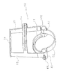
- the locking means also comprise a lug 67 carried by the closure device 60 and apparent on the figure 13 .
- the lug 67 is arranged to engage with the notch 91 when the closure device 60 and the cylinder head 40 are sufficiently close to each other.
- the locking means also comprise a rotation spring 93 tending to engage the notch 91 on the lug 67 and to maintain this cooperation.
- the unlocking means make it possible to separate the cylinder head 40 and the closure device 60.
- they comprise a manually or automatically actuated button 92 and a kinematic assembly making it possible to act on the pivot bearing the notch 91.
- the button 92 When the button 92 is actuated, the pivot rotates about its axis so as to disengage the notch 91 of the lug 67 thus releasing the closure device 60 of the head 41 of the jack 40.
- the closure device 60 When the two half-chambers are remote and the unlocking means are actuated, the closure device 60, under the action of the spacer spring 47 moves forward until it abuts with a seat 21 of stopper carried by the frame 20 substantially at the level of the fixed half-chamber 22.
- the head 41 of the jack 40 is driven in translation forwards until the latter reaches sufficiently close of the closing device 60 so that the notch 91, under the effect of the rotational spring 93, engages the lug 67 of the closure device 60.
- the head 41 of the jack 40 and the closure device 60 are then integral with one another. the other.
- the unlocking device can again be engaged to release the closure device 60 again and give rise to a new cycle.
- the system 10 also comprises guide means 46.
- These guide means 46 have substantially the shape of an elliptical sleeve capable of preventing any significant movement of the package 1 in a horizontal plane, and to allow its vertical movement.
- These guiding means 46 are integral with the head 41 of the jack 40. They are arranged so as to guide the package 1 upstream of the upstream closure means 61. Moreover, they are longitudinally arranged so as to be arranged according to the the opening of the chamber 7 in the first position to allow the introduction of a package 1 in the latter when the upstream closure means 61 are retracted. In the second position, they are arranged to be arranged substantially in front of the chamber 7.
- the guide means 46 contribute to preventing any significant longitudinal translation of the packaging 1. The latter is thus maintained with respect to the opening of the infusion chamber 7 when the means upstream closure 61 are completely retracted.
- the relative movement closing device 60 and guide means 46 thus allows the transfer of the package 1 from the upstream closure means 61 to the chamber 7. By elsewhere, this relative movement makes it possible to protect the integrity of the packaging 1 during this transfer.
- these guiding means 46 make it possible to maintain in position a packaging 1 resting on the upstream closing means 61 so as to facilitate the introduction of this packaging 1 in the chamber 7.
- the guiding means 46 have two grooves substantially parallel and vertical, intended to cooperate with the periphery of the packaging 1 to improve the guidance of the latter.
- the system 10 also comprises a hatch 30 defining an opening disposed upstream of the upstream closing means 61 and upstream of the guiding means 46.
- the opening is arranged longitudinally so as to be located at the right of the upstream closure means 61 when the closure device 60 is disposed in the first position.
- the opening defined by the hatch 30 is accessible by a user and is intended to receive a packaging 1 for its introduction into the system 10.
- the obstruction means 63 comprise an upper stop disposed upstream of the upstream closure means 61, upstream of the guide means 46 and downstream of the opening of the trapdoor 30.
- the upper stop extends from an arm 65 to the other of the closure device 60 and acts as retractable stopper for a packaging 1. It is arranged, along the longitudinal axis 11, substantially to the right of the downstream closure means 62.
- the packaging 1 introduced into the opening of the hatch 30 freely accesses the guide means 46 and comes into abutment on the upstream closure means 61.
- the obstruction means 63 thus prevent a package 1 from being introduced while another package 1 is already present on the upstream closure means 61 or in the chamber 7.
- the obstruction means 63 prevent access to the infusion system 10 which improves the safety of the entire machine. Indeed, in this position a user can not in particular introduce an object or his fingers inside the system 10.
- the closure device 60 is formed of a single piece of material.
- the closure device 60 may for example be made of aluminum, stainless steel or plastic.
- the system 10 comprises a pump for supplying the chamber 7 with fluid. Furthermore, this pump, in the particular example described, also feeds the actuator for closing and opening the chamber 7. In effect, the pump supplies a hydraulic circuit for actuating the jack 40.
- the pump is supplied with electricity by an electric circuit provided with a first and a second switch.
- the first switch closes under the control of a user.
- the control button 92 is linked to the first switch and its actuation closes the first switch.
- the second switch closes when the closure device 60 is disposed in the second position.
- the system 10 comprises servo-control means 80 arranged to serve the operation of the pump as a function of the position of the closure device 60.
- These servocontrol means 80 serve as a second switch and comprise a end of travel switch 81 integral with the frame 20, and a contact finger 68 carried by the closing device 60 and arranged to cooperate with the contactor 81.
- the finger 68 of contact appears on the figure 14 showing in detail the closure device 60.
- the servo means 80 are arranged so that the contactor 81 and the contact finger 68 are in mutual contact when the closure device 60 is disposed in the second position. In this position, the contact finger 68 presses the switch 81 and closes the electrical supply circuit of the pump.
- the pump In this position, the pump is supplied with electricity and can work.
- the circuit When the circuit is open, that is to say when the switch 81 is not pushed by the contact finger 68, the pump can not operate.
- the operation of the pump is subordinated to the proper positioning of the upstream closure means 61 and downstream 62.
- the invention makes it possible to significantly improve the control of the relative position between the upstream closure means 61, the downstream closure means 62, the guide means 46 and the two half-chambers 22, 42.
- the risks of malfunction of the system 1 are therefore substantially reduced.
- the system 10 comprises at the level of the supply circuit of the pump means of alert. These warning means are supplied with electricity when the first switch is closed and the mutual position of the contactor 81 and the contact finger 68 does not allow the supply of the pump.
- the warning means When they are powered, the warning means trigger a visual or audible alert signal, for example, to warn the user that the machine does not operate normally and that an intervention on his part is required.
- This intervention may consist in manually gripping the closing device 60 and returning it to the appropriate position in order to rearm the system 10.
- the latter comprises a gripping element 64 easily accessible by the user by opening an upper cover containing the system 10 for example.
- This gripping element 64 serves as a loop extending in a horizontal plane towards the rear and having two ends respectively connected to one of the arms 65.
- This intervention may also require the removal of a package 1 or any object stuck when it This is the reason for the poor positioning of the pump.
- the system 10 significantly improves security for a user. Indeed, if the upper hatch 30 remains open due to the presence of any obstacle such as particular fingers, the pump does not work and neither the translation of the cylinder 40, nor the injection of water into the chamber 7 born can be engaged. The system therefore has a sequential and conditional operation.
- control means 80 also make it possible to prohibit the operation of the pump, when the presence of an obstacle in the lower part of the system 10 prevents correct positioning of the closure device 60.
- the pump can not operate and the warning means are activated.
- the invention preserves the integrity of a package 1 that would be present in the chamber 7 while the closure device 60 is blocked. Indeed, the actuation of the pump would have the effect of crushing the package 1 and humidify it.
- the system 10 also comprises first stripping means 610 arranged to ensure perfect separation between the packaging 1 and the fixed half chamber 22 after infusion. Indeed, the firm contact between the packaging 1 and the two half-chambers can prevent this packaging 1 is ejected by simply moving away from the fixed half-chamber 22 and by removing the downstream closure means 62.
- These first stripping means 610 have a general shape of edge extending substantially in a form of a crown, this edge being secured to the closure device 60 and disposed at the level of the upstream closure means 61.
- These first stripping means 610 are arranged to come into contact with the around the packaging 1 and to move the latter backwards during the return towards the rear of the closing device 60.
- These first stripping means 610 have a particularly simple structure and contribute to significantly improve the operation of the system 10.
- the system 10 also comprises second stripping means 44 arranged to ensure perfect separation between the mobile half chamber 42 and the package 1 after infusion.
- These second stripping means 44 comprise a stripping shaft 441 mounted to slide longitudinally on the head 41 of jack 40 and whose front end bears a stripping finger 443.
- These second stripping means 44 are arranged in such a way that the stripping spring 442 tends to place the finger 443 in contact with the periphery of a package 1 introduced into the chamber 7 and to move it away from the mobile half-chamber 42.
- the finger 443 is disposed in front of the front end of the mobile half-chamber 42.
- the stripping spring 442 exerts on the package 1 a sufficiently small force not to damage the latter in case of jamming.
- This spring is for example dimensioned so as to exert a force of the order of 0.2 Newton.
- the rear end of the first stripping means 610 is disposed behind the rear end of the fixed half-chamber 22.
- the front end of the second stripping means 44 is disposed in front of the front end of the half moving chamber 42.
- the user introduces a packaging 1 into the opening of the hatch 30.
- This packaging 1 falls by gravity being guided and being maintained in a substantially vertical position by the guide means 46.
- the gravity displacement of this packaging 1 is interrupted by the upstream closing means 61 disposed opposite the opening of the flap 30 and the guide means 46. These upstream closure means 61 prevent the package 1 from accessing the interior of the chamber 7.
- the user actuates the unlocking means via the control button 92.
- These unlocking means make it possible to eliminate the connection between the jack 40 and the closure device 60.
- the latter is then free to slide. to the front under the effect of the spacer spring 47.
- the upstream closing means 61 move forward and the guide means 46 remain fixed, thus the conditioning 1 to the right of the opening of the chamber 7.
- the upstream closure means 61 release the opening of the chamber 7.
- the downstream closure means 62 progressively obstruct the opening of the chamber. room 7 downstream of the latter.
- the jack 40 causes the head 41 of the jack 40 to move forwardly until the two half-chambers form a sealed volume enclosing the package 1.
- the heated water by the boiler and outlet of the tank enters the chamber 7 and closed allowing the infusion of the packaging 1.
- the exhaust pipe 45 carried by the movable half chamber 42 allows the extraction of the drink to the container.
- the notch 91 of the locking means enters into engagement with the lug 67 of the closure device 60 to secure the latter on the head 41 of cylinder 40.
- the head 41 of cylinder 40 under the effect of a return spring acting in compression, initiates its rearward withdrawal driving with it the closing device 60.
- the second means of stripping 44 ensure the separation between the packaging 1 and the mobile half-chamber 42.
- the first stripping means 610 come into contact with the perimeter of the packaging 1 causing the detachment thereof from the fixed half-chamber 22.
- the packaging 1 is located thus arranged between the two half-rooms without being in solidarity with one of them.
- the two half cup-shaped chambers substantially guide the packaging 1 towards the opening of the chamber 7 when they move away from each other.
- the closing device 60 is brought back to the first position: the downstream closure means 62 no longer impede the ejection of the package 1 and the latter can then be discharged to the collection tank of the chamber 7 by gravity.
- the obstructing means 63 leave the opening of the free flap 30 and a new packaging 1 can be inserted into the system 10.
- the invention has a sequential operation that improves the reliability of existing systems, reduce the risk of blockage of the mechanism and preserve the integrity of the packaging.
- the closing device 60 can be arranged to move alternately from the first position to the second position by a movement of rotation and not by a translational movement. This rotation can take place along the longitudinal axis 11, or along a vertical axis or along a horizontal axis perpendicular to the longitudinal axis 11. In each of these cases, it will be ensured that the upstream closing means 61 and the downstream closure means 62 have an appropriate angular offset along the axis of rotation of the closure device 60.
- closure device 60 is arranged to translate in a main direction different from that of the longitudinal axis 11, such as for example a main direction horizontal and perpendicular to the longitudinal axis 11.
- a main direction different from that of the longitudinal axis 11, such as for example a main direction horizontal and perpendicular to the longitudinal axis 11.
- the upstream closing means 61 and downstream 62 of such a device are offset in this main direction.
- the actuation of the movable half-chamber 42 and the closing device 60 is provided by a hydraulic jack 40. In other embodiments, it can be provided to ensure this actuation manually, by means of a lever for example or by means of a motorization for example endless screw or by means of a pneumatic cylinder.
- the opening and closing of the infusion chamber 7 are ensured by the displacement of the two half-chambers.
- the displacement relative to the frame 20 of each of these two half-chambers can be provided either by translation or by rotation.
Landscapes
- Engineering & Computer Science (AREA)
- Food Science & Technology (AREA)
- Mechanical Engineering (AREA)
- Apparatus For Making Beverages (AREA)
- Non-Alcoholic Beverages (AREA)
- Medical Preparation Storing Or Oral Administration Devices (AREA)
- Devices For Dispensing Beverages (AREA)
- Tea And Coffee (AREA)
- Package Closures (AREA)
- Closing Of Containers (AREA)
- Infusion, Injection, And Reservoir Apparatuses (AREA)
- Basic Packing Technique (AREA)
- Processing Of Solid Wastes (AREA)
Abstract
Description
La présente invention concerne un dispositif de production de boissons par infusion d'un produit contenu dans un conditionnement.The present invention relates to a device for producing beverages by infusion of a product contained in a packaging.
Elle trouve plus particulièrement son application dans le domaine des machines à café de type ESPRESSO. Elle pourra également s'appliquer à la production de boissons à partir d'autres matières telles que le thé.It is particularly applicable in the field of ESPRESSO type coffee machines. It may also apply to the production of beverages from other materials such as tea.
De nombreuses machines à café utilisent désormais des conditionnements unitaires et jetables de café moulu. L'utilisateur n'a plus aucun contact direct avec le café moulu, ce qui facilite grandement la manipulation de la mouture et permet la production d'une boisson dans des conditions plus propres.Many coffee machines now use unit and disposable ground coffee packages. The user has no direct contact with the ground coffee, which greatly facilitates the handling of the grind and allows the production of a drink in cleaner conditions.
C'est ainsi que le document
Ce type de machine s'est avéré globalement satisfaisant. Cependant, de part son environnement concurrentiel il doit continuellement faire l'objet d'améliorations. Dans ce cadre, la présente invention vise à améliorer la fiabilité des machines existantes.This type of machine has been generally satisfactory. However, due to its competitive environment, it must continually be improved. In this context, the present invention aims to improve the reliability of existing machines.
Pour atteindre cet objectif, il est prévu selon l'invention un système de production de boisson par infusion d'un produit contenu dans un conditionnement comprenant :
- une chambre d'infusion destinée à recevoir un conditionnement,
- o la chambre comportant deux demi chambres agencées pour être mutuellement éloignées ou rapprochées afin de respectivement fermer ou ouvrir la chambre,
- un dispositif de fermeture comprenant :
- o des moyens de fermeture amont agencés de manière à sélectivement empêcher ou à autoriser l'entrée d'un conditionnement dans la chambre,
- o des moyens de fermeture aval agencés de manière à sélectivement empêcher ou à autoriser la sortie d'un conditionnement hors de la chambre,
- le dispositif de fermeture étant agencé pour passer alternativement :
- o d'une première position dans laquelle :
- les moyens de fermeture amont empêchent l'entrée d'un conditionnement dans la chambre,
- les moyens de fermeture aval autorisent la sortie d'un conditionnement hors de la chambre,
- o à une deuxième position dans laquelle :
- les moyens de fermeture amont autorisent l'entrée d'un conditionnement dans la chambre,
- les moyens de fermeture aval permettent la réception d'un conditionnement introduit dans la chambre et empêchent la sortie de ce dernier hors de la chambre,
le dispositif de fermeture étant agencé de manière à ce que :- la position des moyens de fermeture amont conditionne la position des moyens de fermeture aval,
- la position des moyens de fermeture aval conditionne la position des moyens de fermeture amont.
- o d'une première position dans laquelle :
- an infusion chamber for receiving a package,
- o the chamber comprising two half-chambers arranged to be mutually distant or close together to respectively close or open the chamber,
- a closure device comprising:
- o upstream closure means arranged to selectively prevent or allow entry of a package into the chamber,
- downstream closure means arranged to selectively prevent or allow the exit of a package from the chamber,
- the closing device being arranged to pass alternately:
- o a first position in which:
- the upstream closure means prevent the entry of a packaging into the chamber,
- the downstream closure means allow the output of a package out of the chamber,
- o a second position in which:
- the upstream closure means allow the entry of a packaging into the chamber,
- the downstream closure means allow the reception of a packaging introduced into the chamber and prevent the exit of the latter from the chamber,
the closure device being arranged in such a way that:- the position of the upstream closure means conditions the position of the downstream closure means,
- the position of the downstream closure means conditions the position of the upstream closure means.
- o a first position in which:
Ainsi, l'invention présente un fonctionnement séquentiel. En effet, pour une position donnée des moyens de fermeture amont, les moyens de fermeture aval n'admettent qu'une seule position. Et inversement, pour une position donnée des moyens de fermeture aval, les moyens de fermeture amont n'admettent qu'une seule position. Ainsi, le positionnement relatif entre les moyens de positionnement amont d'une part et aval d'autre part est parfaitement maîtrisé.Thus, the invention has a sequential operation. Indeed, for a given position of the upstream closure means, the downstream closure means admit only one position. Conversely, for a given position of the downstream closure means, the upstream closure means admit only one position. Thus, the relative positioning between the upstream positioning means on the one hand and downstream on the other hand is perfectly controlled.
Or, la demanderesse s'est aperçue que la fiabilité des machines existantes dépend notamment de la maîtrise du positionnement relatif entre les moyens de positionnement amont d'une part et aval d'autre part.However, the Applicant has found that the reliability of existing machines depends in particular on controlling the relative positioning between the upstream positioning means on the one hand and downstream on the other hand.
Ainsi, l'invention permet d'améliorer la fiabilité des machines existantes.Thus, the invention improves the reliability of existing machines.
De manière facultative, l'invention pourra également présenter comme caractéristique additionnelle que le dispositif de fermeture est agencé de manière à ce que les moyens de fermeture amont soient solidaires des moyens de fermeture aval.Optionally, the invention may also have the additional feature that the closure device is arranged so that the upstream closure means are integral with the downstream closure means.
L'invention permet ainsi de diminuer significativement le nombre de pièces mobiles les unes par rapport aux autres ainsi que la complexité de la structure du système. Cette structure permet une simplification de la cinématique des organes permettant de passer alternativement de la première à la deuxième position. Les risques de blocage du mécanisme, le nombre de pièces mis en jeu, le coût de fabrication et le taux de défectuosité sont par conséquent substantiellement réduits.The invention thus makes it possible to significantly reduce the number of moving parts relative to one another as well as the complexity of the structure of the system. This structure allows a simplification of the kinematics of the organs to pass alternately from the first to the second position. The risks of locking the mechanism, the number of parts involved, the manufacturing cost and the defect rate are therefore substantially reduced.
Le système selon l'invention pourra en outre présenter au moins facultativement l'une quelconque des caractéristiques suivantes :
- le système comporte une pompe permettant d'alimenter en fluide la chambre, et/ ou un actionneur permettant de déplacer mutuellement les deux demi chambres et des moyens d'asservissement agencés de manière à asservir le fonctionnement de la pompe et/ou le fonctionnement de l'actionneur en fonction de la position du dispositif de fermeture,
- les moyens de fermeture amont sont agencés de manière à assurer la réception et le maintien d'un conditionnement hors de la chambre dans la première position,
- le dispositif de fermeture est agencé de manière à translater par rapport à un bâti du système pour passer alternativement de la première à la deuxième position,
- le dispositif de fermeture est agencé de manière à tourner par rapport à un bâti du système pour passer alternativement de la première à la deuxième position,
- le système comprend des moyens de guidage agencés de manière à guider le conditionnement en vue de son introduction dans la chambre et à le maintenir au droit de la chambre lors de l'effacement des moyens de fermeture amont,
- le système comprend une trappe définissant une ouverture disposée en amont des moyens de fermeture amont et en ce que le dispositif de fermeture comprend des moyens d'obstruction agencés de manière à laisser libre l'ouverture de la trappe lorsque le dispositif de fermeture est disposé dans la première position et à, obstruer l'ouverture de la trappe lorsque le dispositif de fermeture est disposé dans la deuxième position,
- les moyens de fermeture amont, les moyens de fermeture aval et les moyens d'obstruction sont mutuellement solidaires,
- le dispositif de fermeture est composé d'une pièce unique,
- le système comporte des moyens d'alerte agencés de manière à envoyer un signal d'alerte à un utilisateur lorsque le dispositif de fermeture n'est pas positionné de manière adéquate,
- the system comprises a pump for supplying the chamber with fluid, and / or an actuator for mutually displacing the two half-chambers and the servo-control means arranged in such a way as to control the operation of the pump and / or the operation of the pump. actuator according to the position of the closing device,
- the upstream closing means are arranged so as to ensure the reception and the maintenance of a packaging out of the chamber in the first position,
- the closure device is arranged to translate relative to a frame of the system to pass alternately from the first to the second position,
- the closure device is arranged to rotate relative to a frame of the system to pass alternately from the first to the second position,
- the system comprises guiding means arranged so as to guide the packaging with a view to introducing it into the chamber and keeping it in line with the chamber during the erasing of the upstream closing means,
- the system comprises a hatch defining an opening disposed upstream of the upstream closure means and in that the closing device comprises obstruction means arranged so as to allow the opening of the hatch to be opened when the closure device is disposed in the first position and to obstruct the opening of the hatch when the closing device is arranged in the second position,
- the upstream closure means, the downstream closure means and the obstruction means are mutually integral,
- the closure device is composed of a single piece,
- the system comprises warning means arranged to send an alert signal to a user when the closure device is not positioned adequately,
En outre, il est prévu selon l'invention un dispositif de fermeture apte à sélectivement empêcher et autoriser l'accès à une chambre d'infusion destinée à recevoir un conditionnement pour production de boisson comportant des moyens de fermeture amont destinés à sélectivement empêcher ou autoriser l'accès à la chambre depuis l'amont de cette dernière et des moyens de fermeture aval destinés à sélectivement réceptionner le conditionnement dans la chambre ou à autoriser la sortie du conditionnement hors de la chambre par gravité, les moyens de fermeture amont étant solidaires des moyens de fermeture aval.In addition, there is provided according to the invention a closure device adapted to selectively prevent and allow access to an infusion chamber for receiving a packaging for beverage production comprising upstream closure means for selectively prevent or allow access to the chamber from upstream of the latter and downstream closure means for selectively receive the packaging in the chamber or allow the output of the packaging out of the chamber by gravity, the upstream closure means being secured to the downstream closure means.
Par ailleurs, le dispositif de fermeture présente comme caractéristique additionnelle qu'il est destiné à être déplacer de manière alternative selon au moins une direction principale donnée, en ce que les moyens de fermeture amont et les moyens de fermeture aval sont disposés de manière à présenter un décalage mutuel selon cette direction principale donnée.Moreover, the closure device has the additional feature that it is intended to be moved alternately in at least one given principal direction, in that the upstream closure means and the downstream closure means are arranged in such a way as to present a mutual offset according to this given principal direction.
On prévoit également selon l'invention une machine de production de boisson par infusion d'un produit contenu dans un conditionnement comprenant un système selon l'une quelconque des caractéristiques précédentes ou un dispositif de fermeture selon l'une quelconque des caractéristiques précédentes.Also provided according to the invention is a beverage production machine by infusion of a product contained in a package comprising a system according to any one of the preceding characteristics or a closure device according to any one of the preceding features.
Par ailleurs, il est prévu selon l'invention un procédé de production de boisson par infusion d'un produit contenu dans un conditionnement en utilisant un système selon l'une quelconque des caractéristiques précédentes ou en utilisant un dispositif de fermeture selon l'une quelconque des caractéristiques précédentes, ou encore en utilisant une machine selon la caractéristique précédente.Furthermore, there is provided according to the invention a method of producing beverage by infusing a product contained in a package using a system according to any one of the preceding features or using a closure device according to any one of previous characteristics, or using a machine according to the preceding characteristic.
D'autres caractéristiques, buts et avantages de la présente invention apparaîtront à la lecture de la description détaillée qui va suivre et au regard des dessins annexés donnés à titre d'exemple non limitatif et sur lesquels :
- la
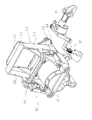
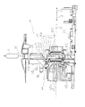
figure 1 est une vue en perspective du coté droit d'un système de production de boissons selon un exemple de réalisation de l'invention, - la
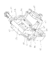
figure 2 est une vue en perspective du coté gauche du système de lafigure 1 , - la
figure 3 est une vue du coté droit du système de lafigure 1 , - la
figure 4 est une vue du coté gauche du système de lafigure 1 , - la
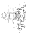
figure 5 est une vue du dessus du système de lafigure 1 , - la
figure 6 est une vue de l'avant du système de lafigure 1 , - les
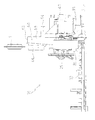
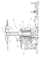
figures 7 à 12 sont des vues en coupe longitudinale du système de lafigure 1 représentant diverses étapes du procédé de production lors du fonctionnement, - les
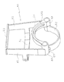
figures 13 et14 sont des vues en perspective respectivement de l'avant et de l'arrière du dispositif de fermeture équipant le système de lafigure 1 .
- the
figure 1 is a perspective view of the right side of a beverage production system according to an exemplary embodiment of the invention, - the
figure 2 is a perspective view of the left side of the system of thefigure 1 , - the
figure 3 is a view of the right side of the system of thefigure 1 , - the
figure 4 is a view on the left side of the system of thefigure 1 , - the
figure 5 is a top view of the system from thefigure 1 , - the
figure 6 is a view from the front of the system thefigure 1 , - the
Figures 7 to 12 are longitudinal sectional views of the system of thefigure 1 representing various stages of the production process during operation, - the
figures 13 and14 are perspective views respectively of the front and the rear of the closing device equipping the system of thefigure 1 .
En référence aux
On qualifiera d'amont et d'aval les portions d'espace respectivement disposées avant et après un point considéré relativement au trajet normal d'un conditionnement 1 dans la machine lors d'un cycle de préparation d'une boisson.Upstream and downstream portions of space respectively disposed before and after a given point relative to the normal path of a
La présente invention utilise des conditionnements du type présentés sur les
Le système 10 selon l'invention comporte une chambre 7 d'infusion destinée à recevoir un conditionnement 1. La chambre 7 comprend deux demi chambres agencées pour être mutuellement éloignées ou rapprochées par un actionneur afin de respectivement fermer ou ouvrir la chambre 7 d'infusion.The
On désignera par demi chambres des pièces aptes à être disposées en contact mutuel ou au contact d'un conditionnement 1 pour former un volume étanche faisant office de chambre 7 d'infusion. L'invention n'implique en aucune manière que les deux demi chambres présentent mutuellement une quelconque symétrie.By half-chambers, parts will be designated capable of being placed in contact with each other or in contact with a
Dans l'exemple de réalisation présenté, l'une des demi chambres, désignée par la suite demi chambre fixe 22, est solidaire d'un bâti 20 de la machine. L'autre demi chambre, désignée demi chambre mobile, est portée par une tête 41 de vérin 40 faisant office d'actionneur autorisant le rapprochement et l'éloignement mutuels des demi chambres. Chacune des demi chambres présente une extrémité définissant un pourtour contenu dans un plan sensiblement perpendiculaire à l'axe longitudinal 11.In the embodiment shown, one of the half chambers, hereinafter referred to as the
On désignera par la suite direction longitudinale la direction comprenant l'axe de translation du vérin 40. On qualifiera de sens avant 12 le sens, selon cet axe contribuant au rapprochement mutuel des deux demi chambres et on qualifiera de sens arrière 13, le sens selon cet axe permettant un éloignement mutuel des deux demi chambres.The direction comprising the axis of translation of the
Dans le cadre de l'exemple de réalisation représenté, la demi chambre fixe 22 présente un conduit d'arrivée 24 d'eau apte à recevoir l'embouchure d'un circuit d'eau chaude. De manière conventionnelle, le circuit d'eau chaude comporte un réservoir, une chaudière permettant d'augmenter la température de l'eau du réservoir jusqu'à une température souhaitée en vue de son infusion dans la chambre 7, ainsi qu'une pompe permettant d'élever la pression de l'eau dans le circuit. Lors de l'infusion, les deux demi chambres sont maintenues fermement au contact l'une de l'autre et délimitent un volume étanche de réception du conditionnement 1. L'étanchéité peut être réalisée par application des pourtours des deux demi chambres sur le pourtour du conditionnement 1 qui fait alors office de joint. L'étanchéité peut également être assurée ou être renforcée des moyens d'étanchéité rapportés.In the context of the embodiment shown, the fixed half-
La demi chambre mobile 42 comporte un conduit d'évacuation 45 de boissons en communication fluidique d'une part avec l'intérieur de la chambre 7 d'infusion et avec une sortie de boisson d'autre part. Ce conduit d'évacuation 45 est destiné à assurer l'évacuation de la boisson résultant de l'infusion du conditionnement 1, vers un contenant tel qu'une tasse à café.The movable half-
Après infusion, lorsque la demi chambre mobile 42 est éloignée de la demi chambre fixe 22, la chambre 7 d'infusion est ouverte, le conditionnement 1 déjà infusé n'est alors plus enserré dans la chambre 7. Ce conditionnement 1 est évacué de la chambre 7 par gravité et tombe dans un bac de récupération.After infusion, when the movable half-
Le système 10 comporte également un dispositif de fermeture 60. Ce dispositif de fermeture 60 comporte des moyens de fermeture aval 62 ainsi que des moyens de fermeture amont 61. Il est distinct de chacune des demi chambres 22, 42 formant la chambre 7 d'infusion.The
Les moyens de fermeture aval 62 sont disposés en aval de la chambre 7 d'infusion. Ils sont agencés de manière à faire office de butée d'arrêt escamotable pour un conditionnement 1 introduit dans la chambre 7.The downstream closure means 62 are disposed downstream of the
Dans une position non escamotée les moyens de fermeture aval 62 assurent la réception d'un conditionnement 1 introduit dans la chambre 7 alors que celle-ci est ouverte, et empêchent l'éjection par gravité de ce conditionnement 1 vers l'aval de la chambre 7.In a non-retracted position, the downstream closure means 62 ensure the reception of a
Dans cette position les moyens de fermeture aval 62 interdisent également toute intrusion dans la chambre 7 depuis l'aval de cette dernière. Ainsi l'utilisateur ne peut pas, par exemple, introduire ses doigts dans la chambre 7.In this position the downstream closure means 62 also prohibit any intrusion into the
Dans une position escamotée, les moyens de fermeture aval 62 ne forment pas une butée d'arrêt pour un conditionnement 1 introduit dans la chambre 7 et permettent donc l'évacuation d'un conditionnement 1 lors de l'ouverture de la chambre 7.In a retracted position, the downstream closure means 62 do not form a stop for a
Les moyens de fermeture amont 61 sont agencés de manière à faire office de butée d'arrêt escamotable. Ils sont disposés en amont de la chambre 7 d'infusion.The upstream closure means 61 are arranged to act as retractable stop stop. They are arranged upstream of the
Dans une position non escamotée les moyens de fermeture amont 61 empêchent l'accès d'un conditionnement 1 ou de tout autre élément dans la chambre 7 d'infusion depuis l'amont de cette dernière. Dans cette position non escamotée les moyens de fermeture amont 61 assurent également la réception et participent au maintien en position d'un conditionnement 1 introduit dans le système 10.In a non-retracted position the upstream closure means 61 prevent access of a
En position escamotée les moyens de fermeture amont 61 autorisent l'introduction d'un conditionnement 1 dans la chambre 7 depuis l'amont de cette dernière.In the retracted position the upstream closure means 61 allow the introduction of a
Le système 10 est agencé de manière à faire passer le dispositif de fermeture 60 alternativement d'une première position dans laquelle les moyens de fermeture amont 61 empêchent l'entrée d'un conditionnement 1 dans la chambre 7, et les moyens de fermeture aval 62 assurent qu'aucun conditionnement 1 usagé ne demeure présent dans la chambre 7, à une deuxième position dans laquelle les moyens de fermeture amont 61 autorisent l'entrée d'un conditionnement 1 dans la chambre 7 et les moyens de fermeture aval 62 permettent la réception et le maintien d'un conditionnement 1 dans la chambre 7.The
Le dispositif de fermeture 60 est agencé de manière à ce que la position des moyens de fermeture amont 61 conditionne la position des moyens de fermeture aval 62, et à ce que la position des moyens de fermeture aval 62 conditionne la position des moyens de fermeture amont 61.The closing
Ainsi, pour une position donnée des moyens de fermeture amont 61, les moyens de fermeture aval 62 n'admettent qu'une seule position et inversement. Le système présente donc un fonctionnement séquentiel.Thus, for a given position of the upstream closure means 61, the downstream closure means 62 admit only one position and vice versa. The system therefore has a sequential operation.
Or, la demanderesse a constaté que dans de nombreux types de systèmes existants les dysfonctionnements sont bien souvent dus à un positionnement relatif incorrect entre les moyens de fermeture amont et les moyens de fermeture aval. Ainsi, l'invention permet de réduire significativement les risques de blocage du système notamment dus au coincement du conditionnement entre des organes mécaniques. Le nombre d'interventions que doit effectuer un utilisateur ou un réparateur est par conséquent réduit. Elle contribue également à préserver l'intégrité du conditionnement 1. Par ailleurs, elle empêche qu'un conditionnement introduit dans la machine ne tombe directement dans le bac de récupération sans avoir été au préalable réceptionné au niveau de la chambre de fusion.However, the Applicant has found that in many types of existing systems malfunctions are often due to incorrect relative positioning between the upstream closure means and the downstream closure means. Thus, the invention makes it possible to significantly reduce the risks of blockage of the system, in particular due to jamming of the packaging between mechanical members. The number of interventions to be performed by a user or a repairer is therefore reduced. It also contributes to preserving the integrity of the
Les moyens de fermeture amont 61 et les moyens de fermeture aval 62 sont solidaires. Cette caractéristique contribue à simplifier la cinématique, à améliorer la robustesse et à limiter le coût de revient et le taux de défectuosité du système 10.The upstream closure means 61 and the downstream closure means 62 are integral. This feature helps to simplify the kinematics, to improve the robustness and to limit the cost price and the rate of defect of the
Les
- deux organes de guidage agencés de manière à guider le dispositif de fermeture 60 dans son déplacement alternatif entre la première et la deuxième position. Chacun des organes de guidage fait office de coulisseau 69 apte à assurer le guidage en translation du dispositif de fermeture 60 selon deux arbres 25, 25 portés par le bâti 20 du système 10 et s'étendant selon deux axes de guidage parallèles à l'axe longitudinal 11,
- deux
bras un coulisseau 69 respectif et dans une direction sensiblement perpendiculaire à l'axe de guidage, - des moyens de fermeture amont 61 agencés de manière à faire office de butée d'arrêt pour
un conditionnement 1 en amont de la chambre 7 lorsque le dispositif de fermeture 60 est disposé dans la première position. De manière avantageuse, les moyens de fermeture amont 61 présentent une forme de portion de couronne dont chacune des extrémités joint l'un desbras - des moyens de fermeture aval 62 agencés de manière à faire office de butée d'arrêt pour
un conditionnement 1 en aval de la chambre 7 lorsque le dispositif de fermeture 60 est disposé dans la deuxième position. De manière avantageuse, les moyens de fermeture aval 62 présentent une forme de portion de couronne dont chacune des extrémités joint l'un des deuxbras
- two guide members arranged to guide the
closing device 60 in its reciprocating movement between the first and the second position. Each of the guiding members acts as aslider 69 capable of guiding theclosing device 60 in translation along twoshafts frame 20 of thesystem 10 and extending along two axes of guide parallel to the axis. longitudinal 11, - two
arms respective slider 69 and in a direction substantially perpendicular to the guide axis, - upstream closure means 61 arranged to serve as a stop for a
conditioning 1 upstream of thechamber 7 when theclosure device 60 is disposed in the first position. Advantageously, the upstream closure means 61 have a crown portion shape, each end of which joins one of thearms - downstream closure means 62 arranged to serve as a stop for a
conditioning 1 downstream of thechamber 7 when theclosure device 60 is disposed in the second position. Advantageously, the downstream closure means 62 have a crown portion shape, each end of which joins one of the twoarms
Par ailleurs, les moyens de fermeture amont 61 et aval 62 sont disposés de manière à présenter un décalage mutuel selon la direction principale de déplacement du dispositif de fermeture 60. Ainsi, dans la deuxième position les moyens de fermeture amont 61 sont disposés sensiblement en arrière de la demi chambre fixe 22. Dans la première position les moyens de fermeture amont 61 sont disposés sensiblement en avant de la demi chambre fixe 22. Dans la première position les moyens de fermeture aval 62 sont disposés essentiellement en arrière de la demi chambre mobile 42.Furthermore, the upstream closure means 61 and downstream 62 are arranged to have a mutual offset in the main direction of movement of the
Les dimensions de ce décalage sont choisies de manière à ce que :
- lorsque le dispositif de fermeture 60 est disposé dans la première position, les moyens de fermeture amont 61 empêchent l'entrée d'un conditionnement 1 dans
la chambre 7, et les moyens de fermeture aval 62 autorisent la sortie d'un conditionnement 1 usagé hors de la chambre 7, - lorsque le dispositif de fermeture 60 est disposé dans la deuxième position les moyens de fermeture amont 61 autorisent l'entrée d'un conditionnement 1 dans
la chambre 7, les moyens de fermeture aval 62 permettent la réception et le maintien d'un conditionnement 1 introduit dans la chambre 7.
- when the
closure device 60 is disposed in the first position, the upstream closure means 61 prevent the entry of apackage 1 into thechamber 7, and the downstream closure means 62 allow the exit of a usedpackage 1 out of frombedroom 7, - when the
closure device 60 is disposed in the second position, the upstream closure means 61 allow the entry of apackage 1 into thechamber 7, the downstream closure means 62 allow the reception and maintenance of apackage 1 introduced in thebedroom 7.
Ainsi dans cet exemple le dispositif de fermeture 60 étant monté coulissant sur l'axe longitudinal 11, les moyens de fermeture amont 61 et aval 62 présentent un décalage mutuel selon l'axe longitudinal 11. Les moyens de fermeture amont 61 sont disposés en avant des moyens de fermeture aval 62 selon ce même axe.Thus in this example the
Le système 10 comporte des moyens d'actionnement permettant le passage alternatif de la première à la deuxième position. Ce sont les mêmes moyens d'actionnement qui agissent à la fois sur les moyens de fermeture amont 61 et sur les moyens de fermeture aval 62.The
Le système 10 permet par conséquent de limiter considérablement les risques de coincement des conditionnements. Notamment, le système 10 empêche :
qu'un conditionnement 1 introduit dans le système 10 ne tombe directement dans le bac de récupération sans avoir subi une infusion. En effet,la chambre 7 d'infusion est soit obstruée en amont par les moyens de fermeture amont 61 soit en aval par les moyens de fermetureaval 62.- que deux conditionnements puissent être simultanément présents dans la chambre 7 d'infusion.
- that a
conditioning 1 introduced into thesystem 10 does not fall directly into the recovery tank without having undergone an infusion. Indeed, theinfusion chamber 7 is either obstructed upstream by the upstream closure means 61 or downstream by the downstream closure means 62. - that two packages can be simultaneously present in the
infusion chamber 7.
Le nombre d'actionneurs étant réduits, la complexité de la structure du système 10 s'en trouve significativement limitée. Cette structure permet une simplification de la cinématique des organes permettant de passer alternativement de la première à la deuxième position. L'encombrement et le nombre de pièces mises en jeu, le coût de fabrication ainsi que le taux de défectuosité sont par conséquent substantiellement réduits.The number of actuators being reduced, the complexity of the structure of the
Les deux arbres 25, 25 sur lesquels coulissent les deux organes de guidage du dispositif de fermeture 60 participent à la liaison glissière de la tête 41 du vérin 40.The two
Un ressort d'écartement 47 tend à pousser le dispositif de fermeture 60 vers l'avant et à écarter le dispositif de fermeture 60 de la tête 41 du vérin 40.A
De manière préférentielle, on dimensionnera le ressort d'écartement 47 de manière à ce qu'un coincement du conditionnement 1 entre le dispositif de fermeture 60 et un autre élément du système 10 ne nuise pas à l'intégrité du conditionnement 1. Ainsi, on choisira par exemple un ressort exerçant sur le dispositif de fermeture 60 une force d'environ 1,5 Newton.Preferably, the
L'extrémité avant des arbres 25, 25 est liée au bâti 20 et l'extrémité arrière de ces arbres est liée à la partie fixe du vérin 40. Sur chaque axe de guidage définit par un arbre 25 sont respectivement disposés selon la direction longitudinale depuis l'avant vers l'arrière : l'extrémité avant d'un arbre 25, un coulisseau 69 du dispositif de fermeture 60, un ressort d'écartement 47, la tête 41 de vérin 40 et enfin l'extrémité arrière d'un arbre 25.The front end of the
Le déplacement vers l'arrière du dispositif de fermeture 60 ainsi que l'enclenchement du déplacement du dispositif de fermeture 60 dans un sens ou dans l'autre seront décrits plus en détail par la suite.The rearward movement of the
Par ailleurs, le système 10 comporte également des moyens de solidarisation permettant de solidariser automatiquement et de manière réversible le dispositif de fermeture 60 sur la tête 41 de vérin 40 lorsque ces deux éléments sont suffisamment proches. Les moyens de solidarisation comprennent des moyens de verrouillage et des moyens de déverrouillage.Furthermore, the
Les moyens de verrouillage comprennent un cran 91 porté par une extrémité d'un pivot et monté à rotation sur la tête 41 de vérin 40 selon un axe horizontal perpendiculaire à l'axe longitudinal 11.The locking means comprise a
Les moyens de verrouillage comprennent également un ergot 67 porté par le dispositif de fermeture 60 et apparent sur la
Par ailleurs, les moyens de verrouillage comprennent également un ressort de rotation 93 tendant à engager le cran 91 sur l'ergot 67 et à maintenir cette coopération. Ainsi, lorsque le dispositif de fermeture 60 est suffisamment proche de la tête 41 de vérin 40, le cran 91 et l'ergot 67 coopèrent pour permettre la solidarisation du dispositif de fermeture 60 sur la tête 41 de vérin 40.Furthermore, the locking means also comprise a
Les moyens de déverrouillage permettent de désolidariser la tête 41 de vérin 40 et le dispositif de fermeture 60. A cet effet, ils comportent un bouton 92 de commande actionné de manière manuelle ou automatique ainsi qu'un ensemble cinématique permettant d'agir sur le pivot portant le cran 91. Lorsque le bouton 92 est actionné, le pivot tourne autour de son axe de manière à dégager le cran 91 de l'ergot 67 libérant ainsi le dispositif de fermeture 60 de la tête 41 du vérin 40.The unlocking means make it possible to separate the
Lorsque les deux demi chambres sont éloignées et que les moyens de déverrouillage sont actionnés, le dispositif de fermeture 60, sous l'action du ressort d'écartement 47 se déplace vers l'avant jusqu'à entrer en butée avec un siège 21 de butée d'arrêt portée par le bâti 20 sensiblement au niveau de la demi chambre fixe 22. Lorsque le vérin 40 est actionné, la tête 41 de vérin 40 est entraînée en translation vers l'avant jusqu'à ce que cette dernière arrive suffisamment près du dispositif de fermeture 60 pour que le cran 91, sous l'effet du ressort de rotation 93, engage l'ergot 67 du dispositif de fermeture 60. La tête 41 de vérin 40 et le dispositif de fermeture 60 sont alors solidaires l'un de l'autre. Lorsque la tête 41 de vérin 40 est ramenée en arrière, la coopération du cran 91 et de l'ergot 67 maintient la solidarisation entre la tête 41 de vérin 40 et le dispositif de fermeture 60, entraînant ce dernier également vers l'arrière. II est à noter que le dimensionnement du ressort de compression disposé entre le dispositif de fermeture 60 et la tête 41 de vérin 40 ne permet pas de rompre cette solidarisation.When the two half-chambers are remote and the unlocking means are actuated, the
Une fois la tête 41 de vérin 40 arrivée en butée sur la partie fixe du vérin 40, le dispositif de déverrouillage peut à nouveau être enclenché pour libérer à nouveau le dispositif de fermeture 60 et donner lieu à un nouveau cycle.Once the
Le système 10 comporte également des moyens de guidage 46. Ces moyens de guidage 46 présentent sensiblement la forme d'un manchon elliptique apte à empêcher tout mouvement significatif du conditionnement 1 dans un plan horizontal, et à autoriser son déplacement vertical. Ces moyens de guidage 46 sont solidaires de la tête 41 de vérin 40. Ils sont agencés de manière à assurer le guidage du conditionnement 1 en amont des moyens de fermeture amont 61. Par ailleurs, ils sont longitudinalement disposés de manière à être disposés au regard de l'ouverture de la chambre 7 dans la première position afin d'autoriser l'introduction d'un conditionnement 1 dans cette dernière lorsque les moyens de fermeture amont 61 sont escamotés. Dans la deuxième position, ils sont agencés de manière à être disposés sensiblement en avant de la chambre 7.The
Par ailleurs, ils sont verticalement disposés de manière à être suffisamment proches des moyens de fermeture amont 61 pour assurer le maintien du conditionnement 1 lorsque ce dernier repose sur les moyens de fermeture amont 61. Ainsi, lorsqu'un conditionnement 1 repose sur les moyens de fermeture amont 61 et que ces derniers translatent vers l'avant, les moyens de guidage 46 contribuent à empêcher toute translation longitudinale significative du conditionnement 1. Ce dernier est donc maintenu au regard de l'ouverture de la chambre 7 d'infusion lorsque les moyens de fermeture amont 61 sont totalement escamotés. Le mouvement relatif dispositif de fermeture 60 et des moyens de guidage 46 permet ainsi le transfert du conditionnement 1 depuis les moyens de fermeture amont 61 à la chambre 7. Par ailleurs, ce mouvement relatif permet de protéger l'intégrité du conditionnement 1 lors de ce transfert.Furthermore, they are vertically arranged so as to be sufficiently close to the upstream closure means 61 to ensure the maintenance of the
En outre, ces moyens de guidage 46 permettent de maintenir en position un conditionnement 1 reposant sur les moyens de fermeture amont 61 de manière à faciliter la mise en place de ce conditionnement 1 dans la chambre 7. Les moyens de guidage 46 présentent deux rainures sensiblement parallèles et verticales, destinées à coopérer avec le pourtour du conditionnement 1 afin d'améliorer le guidage de ce dernier.In addition, these guiding means 46 make it possible to maintain in position a
Le système 10 comprend également une trappe 30 définissant une ouverture disposée en amont des moyens de fermeture amont 61 et en amont des moyens de guidage 46. L'ouverture est disposée longitudinalement de manière à être située au droit des moyens de fermeture amont 61 lorsque le dispositif de fermeture 60 est disposé dans la première position. L'ouverture définit par la trappe 30 est accessible par un utilisateur et est destinée à recevoir un conditionnement 1 pour son introduction dans le système 10.The
Le dispositif de fermeture 60 comporte des moyens d'obstruction 63 agencés de manière à :
- obstruer l'ouverture de la trappe 30 lorsque le dispositif de fermeture 60 est disposé dans la deuxième position,
- laisser libre l'ouverture de la trappe 30 lorsque le dispositif de fermeture 60 est disposé dans la première position.
- obstruct the opening of the
hatch 30 when theclosure device 60 is arranged in the second position, - leave free the opening of the
hatch 30 when theclosure device 60 is disposed in the first position.
Les moyens d'obstruction 63 comprennent une butée supérieure disposée en amont des moyens de fermeture amont 61, en amont des moyens de guidage 46 et en aval de l'ouverture de la trappe 30. La butée supérieure s'étend d'un bras 65 à l'autre du dispositif de fermeture 60 et fait office de butée d'arrêt escamotable pour un conditionnement 1. Elle est disposée, selon l'axe longitudinal 11, sensiblement au droit des moyens de fermeture aval 62.The obstruction means 63 comprise an upper stop disposed upstream of the upstream closure means 61, upstream of the guide means 46 and downstream of the opening of the
Ainsi, lorsque le dispositif de fermeture 60 est disposé dans la première position, le conditionnement 1 introduit dans l'ouverture de la trappe 30 accède librement aux moyens de guidage 46 et arrive en butée sur les moyens de fermeture amont 61.Thus, when the
Lorsque le dispositif de fermeture 60 est disposé dans la deuxième position, l'introduction d'un conditionnement 1 dans l'ouverture de la trappe 30 est stoppée en amont des moyens de guidage 46 par les moyens d'obstruction 63. Ce conditionnement 1 n'accède donc ni aux moyens de fermeture amont 61 ni aux moyens de fermeture aval 62, ni à la chambre 7.When the
Les moyens d'obstruction 63 empêchent ainsi qu'un conditionnement 1 ne soit introduit alors qu'un autre conditionnement 1 est déjà présent sur les moyens de fermeture amont 61 ou dans la chambre 7.The obstruction means 63 thus prevent a
Par ailleurs, lorsque le dispositif de fermeture 60 est dans la deuxième position, les moyens d'obstruction 63 empêchent tout accès au système 10 d'infusion ce qui permet d'améliorer la sécurité de l'ensemble de la machine. En effet, dans cette position un utilisateur ne peut notamment introduire un objet ou ses doigts à l'intérieur du système 10.Furthermore, when the
Avantageusement, le dispositif de fermeture 60 est formé d'une pièce unique venue de matière. Le dispositif de fermeture 60 pourra par exemple être constitué en aluminium, en acier inoxydable ou encore en plastique.Advantageously, the
Comme indiqué précédemment, le système 10 comporte une pompe destinée à alimenter la chambre 7 en fluide. Par ailleurs, cette pompe, dans l'exemple particulier décrit, alimente également l'actionneur permettant de fermer et d'ouvrir la chambre 7. En effet, la pompe alimente un circuit hydraulique d'actionnement du vérin 40.As indicated above, the
La pompe est alimentée en électricité par un circuit électrique muni d'un premier et d'un deuxième interrupteur.The pump is supplied with electricity by an electric circuit provided with a first and a second switch.
Le premier interrupteur se ferme sous la commande d'un utilisateur. Avantageusement, le bouton de commande 92 est lié au premier interrupteur et son actionnement permet de fermer le premier interrupteur.The first switch closes under the control of a user. Advantageously, the
Le deuxième interrupteur se ferme lorsque le dispositif de fermeture 60 est disposé dans la deuxième position. De manière plus précise, le système 10 comporte des moyens d'asservissement 80 agencés de manière à servir le fonctionnement de la pompe en fonction de la position du dispositif de fermeture 60. Ces moyens d'asservissement 80 font office de deuxième interrupteur et comportent un contacteur 81 de fin de course solidaire du bâti 20, ainsi qu'un doigt de contact 68 porté par le dispositif de fermeture 60 et agencé de manière à coopérer avec le contacteur 81. Le doigt 68 de contact apparaît sur la
Ainsi, l'invention permet d'améliorer significativement la maîtrise de la position relative entre les moyens de fermeture amont 61, les moyens de fermeture aval 62, les moyens de guidage 46 et les deux demi chambres 22, 42. Les risques de dysfonctionnement du système 1 sont par conséquent substantiellement réduits.Thus, the invention makes it possible to significantly improve the control of the relative position between the upstream closure means 61, the downstream closure means 62, the guide means 46 and the two half-
Le deuxième interrupteur admet deux positions :
- une position dite de fonctionnement dans laquelle il permet de fermer le circuit de commande de la pompe. Cette position de fonctionnement est obtenue lorsque le dispositif de fermeture 60 est plaqué contre la
demi chambre fixe 22, et que le bouton de commande 92 a été actionné par un utilisateur. - une position dite de non fonctionnement, dans laquelle il permet de fermer un circuit alimentant en électricité des moyens d'alerte.
- a so-called operating position in which it closes the control circuit of the pump. This operating position is obtained when the
closing device 60 is pressed against the fixed half-chamber 22, and thecontrol button 92 has been actuated by a user. - a so-called non-operating position, in which it makes it possible to close a circuit supplying electricity to the warning means.
En effet, le système 10 comporte au niveau du circuit d'alimentation de la pompe des moyens d'alerte. Ces moyens d'alerte sont alimentés en électricité lorsque le premier interrupteur est fermé et que la position mutuelle du contacteur 81 et du doigt de contact 68 ne permet pas l'alimentation de la pompe.Indeed, the
Lorsqu'ils sont alimentés, les moyens d'alerte déclenchent un signal d'alerte visuel ou sonore par exemple, destiné à avertir l'utilisateur que la machine ne fonctionne pas normalement et qu'une intervention de sa part est requise. Cette intervention peut consister à saisir manuellement le dispositif de fermeture 60 et à le ramener dans la position adéquate afin de réarmer le système 10. A cet effet, ce dernier comprend un élément de préhension 64 aisément accessible par l'utilisateur en ouvrant un capot supérieur contenant le système 10 par exemple. Cet élément de préhension 64 fait office de anse s'étendant dans un plan horizontal vers l'arrière et présentant deux extrémités liées respectivement à un des bras 65. Cette intervention peut également nécessiter de retirer un conditionnement 1 ou un objet quelconque coincé lorsque celui-ci est à l'origine du mauvais positionnement de la pompe.When they are powered, the warning means trigger a visual or audible alert signal, for example, to warn the user that the machine does not operate normally and that an intervention on his part is required. This intervention may consist in manually gripping the
Par conséquent, le système 10 permet d'améliorer significativement la sécurité pour un utilisateur. En effet, si la trappe 30 supérieure reste ouverte du fait de la présence d'un obstacle quelconque tel notamment que des doigts, la pompe ne fonctionne pas et ni la translation du vérin 40, ni l'injection d'eau dans la chambre 7 ne peuvent être enclenchées. Le système présente donc un fonctionnement séquentiel et conditionnel.Therefore, the
Par ailleurs, les moyens d'asservissement 80 permettent également d'interdire le fonctionnement de la pompe, lorsque la présence d'un obstacle en partie basse du système 10 empêche un positionnement correct du dispositif de fermeture 60. Ainsi, lorsque le bac de récupération est plein et qu'un conditionnement 1 déjà infusé ne peut être évacué correctement et empêche le fonctionnement adéquat du dispositif de fermeture 60, la pompe ne peut fonctionner et les moyens d'alerte sont activés.Moreover, the control means 80 also make it possible to prohibit the operation of the pump, when the presence of an obstacle in the lower part of the
En outre, l'invention permet de préserver l'intégrité d'un conditionnement 1 qui serait présent dans la chambre 7 alors que le dispositif de fermeture 60 est bloqué. En effet, l'actionnement de la pompe aurait pour effet d'écraser le conditionnement 1 et de l'humidifier.In addition, the invention preserves the integrity of a
Le système 10 comporte également des premiers moyens de dévêtissement 610 agencés de manière à assurer un parfait décollement entre le conditionnement 1 et la demi chambre fixe 22 après infusion. En effet, le contact ferme entre le conditionnement 1 et les deux demi chambres peut empêcher que ce conditionnement 1 soit éjecté par simple éloignement de la demi chambre fixe 22 et par retrait des moyens de fermeture aval 62. Ces premiers moyens de dévêtissement 610 présentent une forme générale d'arête s'étendant sensiblement selon une forme de couronne, cette arête étant solidaire du dispositif de fermeture 60 et disposés au niveau des moyens de fermeture amont 61. Ces premiers moyens de dévêtissement 610 sont agencés de manière à entrer au contact du pourtour du conditionnement 1 et à déplacer ce dernier vers l'arrière lors du retour vers l'arrière du dispositif de fermeture 60. Ces premiers moyens de dévêtissement 610 présentent une structure particulièrement simple et contribuent à améliorer significativement le fonctionnement du système 10.The
Le système 10 comporte également des deuxièmes moyens de dévêtissement 44 agencés de manière à assurer un décollement parfait entre la demi chambre mobile 42 et le conditionnement 1 après infusion. Ces deuxièmes moyens de dévêtissement 44 comprennent un arbre 441 de dévêtissement monté à coulissement longitudinal sur la tête 41 de vérin 40 et dont l'extrémité avant porte un doigt 443 de dévêtissement.The
Un ressort de dévêtissement 442 agissant en compression et disposé sur l'arbre 441 de dévêtissement entre la tête 41 de vérin 40 et le doigt 443. II tend à repousser ce dernier vers l'avant.A stripping spring 442 acting in compression and disposed on the stripping
Ces deuxièmes moyens de dévêtissement 44 sont agencés de manière à ce que le ressort de dévêtissement 442 tende à placer le doigt 443 au contact du pourtour d'un conditionnement 1 introduit dans la chambre 7 et à écarter ce dernier de la demi chambre mobile 42. Lors du dévêtissement, le doigt 443 est disposé en avant de l'extrémité avant de la demi chambre mobile 42.These second stripping
Le ressort de dévêtissement 442 exerce sur le conditionnement 1 un effort suffisamment faible pour ne pas endommager ce dernier en cas de coincement. Ce ressort est par exemple dimensionné de manière à exercer un effort de l'ordre de 0,2 Newton.The stripping spring 442 exerts on the package 1 a sufficiently small force not to damage the latter in case of jamming. This spring is for example dimensioned so as to exert a force of the order of 0.2 Newton.
En référence aux
En début de cycle, la tête 41 de vérin 40 est repoussée en arrière, la demi chambre mobile 42 est alors éloignée de la demi chambre fixe 22 et la chambre 7 est donc dans sa position ouverte. Les moyens de solidarisation 90 assurent un contact ferme entre la tête 41 de vérin 40 et le dispositif de fermeture 60. Ce dernier est donc disposé dans la première position. Ainsi :
- les moyens de fermeture amont 61 empêchent l'accès à la chambre 7 d'infusion depuis la partie amont de cette dernière,
- les moyens de fermeture aval 62 permettent l'éjection par gravité d'un conditionnement 1 déjà infusé et présent dans la chambre 7,
- les moyens d'obstruction 63 laissent libre l'ouverture de la trappe 30,
- les moyens de guidage 46 sont disposés au droit de l'ouverture de la trappe 30.
- the upstream closure means 61 prevent access to the
infusion chamber 7 from the upstream part thereof, - the downstream closure means 62 allow the gravity ejection of a
package 1 already infused and present in thechamber 7, - the obstruction means 63 leave free the opening of the
hatch 30, - the guide means 46 are arranged at the right of the opening of the
hatch 30.
Par ailleurs, l'extrémité arrière des premiers moyens de dévêtissement 610 est disposée en arrière de l'extrémité arrière de la demi chambre fixe 22. L'extrémité avant des deuxièmes moyens de dévêtissement 44 est disposée en avant de l'extrémité avant de la demi chambre mobile 42. Ainsi, aucun conditionnement 1 déjà infusé ne se trouve entre les deux demi chambres.Moreover, the rear end of the first stripping
L'utilisateur introduit un conditionnement 1 dans l'ouverture de la trappe 30. Ce conditionnement 1 tombe par gravité en étant guidé et en étant maintenu en position sensiblement verticale par les moyens de guidage 46. Le déplacement par gravité de ce conditionnement 1 est interrompu par les moyens de fermeture amont 61 disposés au regard de l'ouverture de la trappe 30 et des moyens de guidage 46. Ces moyens de fermeture amont 61 empêchent au conditionnement 1 d'accéder à l'intérieur de la chambre 7.The user introduces a
Dans une étape ultérieure, l'utilisateur actionne les moyens de déverrouillage par l'intermédiaire du bouton de commande 92. Ces moyens de déverrouillage permettent de supprimer la solidarisation entre le vérin 40 et le dispositif de fermeture 60. Ce dernier est alors libre de coulisser vers l'avant sous l'effet du ressort d'écartement 47. Lors de ce déplacement, les moyens de fermeture amont 61 se déplacent vers l'avant et les moyens de guidage 46 restent fixes maintenant ainsi le conditionnement 1 au droit de l'ouverture de la chambre 7. Au fur et à mesure de leur déplacement vers l'avant, les moyens de fermeture amont 61 libèrent l'ouverture de la chambre 7. Par ailleurs, les moyens de fermeture aval 62 obstruent progressivement l'ouverture de la chambre 7 en aval de cette dernière. Lorsque l'ouverture de la chambre 7, dégagée par les moyens de fermeture amont 61 est suffisamment importante, le conditionnement 1 s'introduit par gravité dans la chambre 7 où il est réceptionné par les moyens de fermeture aval 62 formant une butée d'arrêt.In a subsequent step, the user actuates the unlocking means via the
Le déplacement vers l'avant du dispositif de fermeture 60 se poursuit jusqu'à ce que la butée mobile de fin de course 66 portée par ce dernier entre au contact du siège de butée 21 porté par le bâti 20. Dans cette position le dispositif de fermeture 60 est disposé dans la deuxième position. Dans cette position :
- les moyens de fermeture amont 61 permettent l'accès à la chambre 7 d'infusion depuis l'amont de cette dernière,
- les moyens de fermeture aval 62 assurent la réception du conditionnement 1 introduit dans la chambre 7,
- les moyens d'obstruction 63 obstruent l'ouverture de la trappe 30 empêchant ainsi l'introduction de conditionnements ou de tout autre objet à travers cette dernière,
- le contacteur 81 est au contact du doigt 443 et les moyens d'asservissement 80 permettent le fonctionnement de la pompe.
- the upstream closure means 61 allow access to the
infusion chamber 7 from upstream of the latter, - the downstream closure means 62 ensure the reception of the
packaging 1 introduced into thechamber 7, - the obstructing means 63 obstruct the opening of the
hatch 30 thus preventing the introduction of packaging or any other object through the latter, - the
contactor 81 is in contact with thefinger 443 and the servocontrol means 80 allow the operation of the pump.
Le circuit hydraulique du vérin étant alimenté par la pompe, le vérin 40 entraîne le déplacement de la tête 41 de vérin 40 vers l'avant jusqu'à ce que les deux demi chambres forment un volume étanche enserrant le conditionnement 1. L'eau chauffée par la chaudière et issue du réservoir pénètre dans la chambre 7 ainsi fermée permettant l'infusion du conditionnement 1. Le conduit d'évacuation 45 porté par la demi chambre mobile 42 permet l'extraction de la boisson vers le contenant.The hydraulic circuit of the jack being fed by the pump, the
Lorsque la tête 41 de vérin 40 est appliquée fermement contre le pourtour du conditionnement 1 et l'extrémité arrière de la demi chambre fixe 22, le cran 91 des moyens de verrouillage entre en coopération avec l'ergot 67 du dispositif de fermeture 60 de manière à solidariser ce dernier sur la tête 41 de vérin 40.When the head 41 of the
Une fois l'infusion terminée, la tête 41 de vérin 40, sous l'effet d'un ressort de retour agissant en compression, amorce son retrait vers l'arrière entraînant avec elle le dispositif de fermeture 60. Les deuxièmes moyens de dévêtissement 44 assurent le décollement entre le conditionnement 1 et la demi chambre mobile 42.Once the infusion is over, the head 41 of
Au cours de la translation vers l'arrière du dispositif de fermeture 60, les premiers moyens de dévêtissement 610 entrent au contact du pourtour du conditionnement 1 entraînant le décollement de celle-ci par rapport à la demi chambre fixe 22. Le conditionnement 1 se trouve ainsi disposé entre les deux demi chambres sans être pour autant solidaires de l'une d'elles.During the rearward translation of the
Les deux demi chambres en forme de coupelles assurent sensiblement un guidage du conditionnement 1 vers l'ouverture de la chambre 7 lorsqu'elles s'éloignent mutuellement. Le dispositif de fermeture 60 est ramené jusqu'à la première position : les moyens de fermeture aval 62 n'entravent plus l'éjection du conditionnement 1 et ce dernier peut alors être évacué vers le bac de récupération de la chambre 7 par gravité. Par ailleurs, les moyens d'obstruction 63 laissent l'ouverture de la trappe 30 libre et un nouveau conditionnement 1 peut être inséré dans le système 10.The two half cup-shaped chambers substantially guide the
Avantageusement, l'invention présente un fonctionnement séquentiel qui permet d'améliorer la fiabilité des systèmes existants, de limiter les risques de blocage du mécanisme et de préserver l'intégrité du conditionnement.Advantageously, the invention has a sequential operation that improves the reliability of existing systems, reduce the risk of blockage of the mechanism and preserve the integrity of the packaging.
Par ailleurs, elle présente une structure et une cinématique simples. Elle présente un nombre de pièce, un coût de fabrication, un taux de défectuosité et une difficulté d'entretien réduitsIn addition, it has a simple structure and kinematics. It has a reduced workpiece count, manufacturing cost, defect rate and maintenance difficulty
En outre, elle présente un fonctionnement conditionnel, la pompe étant asservie en fonction du positionnement du dispositif de fermeture. La fiabilité du système ainsi que la sécurité des utilisateurs s'en trouvent renforcées et l'intégrité du conditionnement est préservée.In addition, it has a conditional operation, the pump being controlled according to the positioning of the closure device. The reliability of the system and the safety of the users are strengthened and the integrity of the packaging is preserved.
De plus, elle présente une robustesse améliorée et un encombrement réduit.In addition, it has improved robustness and reduced size.
De nombreuses variantes peuvent être apportées au dispositif décrit précédemment sans sortir pour autant du cadre de l'invention.Many variants can be made to the device described above without departing from the scope of the invention.
Notamment, le dispositif de fermeture 60 peut être agencé pour passer alternativement de la première position à la deuxième position par un mouvement de rotation et non pas par un mouvement translation. Cette rotation peut s'effectuer selon l'axe longitudinal 11, ou selon un axe vertical ou encore selon un axe horizontal perpendiculaire à l'axe longitudinal 11. Dans chacun de ces cas, on veillera à ce que les moyens de fermeture amont 61 et les moyens de fermeture aval 62 présentent un décalage angulaire approprié selon l'axe de rotation du dispositif de fermeture 60.In particular, the closing
On pourra également prévoir que le dispositif de fermeture 60 soit agencé de manière à translater suivant une direction principale différente de celle de l'axe longitudinal 11, comme par exemple une direction principale horizontale et perpendiculaire à l'axe longitudinal 11. Pour un tel dispositif de fermeture 60 les moyens de fermeture amont 61 et aval 62 d'un tel dispositif sont décalés selon cette direction principale.It may also be provided that the
Dans l'exemple décrit précédemment, l'actionnement de la demi chambre mobile 42 et du dispositif de fermeture 60 est assuré par un vérin 40 hydraulique. Dans d'autres modes de réalisation, on peut prévoir d'assurer cet actionnement manuellement, au moyen d'un levier par exemple ou au moyen d'une motorisation par exemple à visse sans fin ou encore au moyen d'un vérin pneumatique.In the example described above, the actuation of the movable half-
On pourra également prévoir que l'ouverture et la fermeture de la chambre 7 d'infusion soient assurées par le déplacement des deux demi chambres. Par ailleurs, le déplacement par rapport au bâti 20 de chacune de ces deux demi chambres peut être assuré soit par translation soit par rotation.It may also be provided that the opening and closing of the
L'adaptation du système 10 décrit précédemment à des conditionnements différents de celui représenté sur les figures peut être effectuée aisément en modifiant simplement les dimensions et la configuration des moyens de fermeture amont 61 et aval 62, des moyens de guidage 46, de l'ouverture de la trappe 30 ainsi que des deux demi chambres 22, 42.The adaptation of the
- 1. Conditionnement1. Conditioning
- 10. Système10. System
-
11. Axe longitudinal 1111.
Longitudinal axis 11 - 12. Sens avant12. Meaning before
- 13. Sens arrière13. Backward direction
- 20. Bâti20. Building
- 21. Siège de butée21. Stop seat
- 22. Demi chambre fixe22. Half fixed room
- 24. Conduit d'arrivée24. Arrival duct
- 25. Arbre25. Tree
- 30. Trappe30. Trap
- 40. Vérin40. Cylinder
- 41. Tête de vérin41. Cylinder head
- 42. Demi chambre mobile42. Half moving room
- 44. Deuxièmes moyens de dévêtissement44. Second means of stripping
- 441. Arbre de dévêtissement441. Tree of stripping
- 442. Ressort de dévêtissement442. Wringing spring
- 443. Doigt443. Finger
- 45. Conduit d'évacuation45. Exhaust duct
- 46. Moyens de guidage46. Means of guidance
- 47. Ressort d'écartement47. Spreader spring
- 60. Dispositif de fermeture60. Closure device
- 61. Moyens de fermeture amont61. Means of upstream closure
- 62. Moyens de fermeture aval62. Means of downstream closure
- 63. Moyens d'obstruction63. Means of obstruction
- 64. Elément de préhension64. Gripping element
- 65. Bras65. Bras
- 66. Butée mobile de fin de course66. Moving end stop
- 67. Ergot67. Ergot
- 68. Doigt de contact68. Contact finger
- 69. Coulisseau69. Slider
- 610. Premiers moyens de dévêtissement610. First means of stripping
- 7. Chambre7. Room
- 80. Moyens d'asservissement80. Means of enslavement
- 81. Contacteur81. Contactor
- 90. Moyens de solidarisation90. Means of solidarity
- 91. Cran91. Cran
- 92. Bouton de commande92. Command button
- 93. Ressort de rotation93. Rotation spring
Claims (15)
o la chambre (7) comportant deux demi chambres (22, 42) agencées pour être mutuellement éloignées ou rapprochées afin de respectivement fermer ou ouvrir la chambre (7),
le dispositif de fermeture (60) étant agencé de manière à ce que :
caractérisé en ce qu'il comporte des moyens d'alerte agencés de manière à envoyer un signal d'alerte à un utilisateur lorsque le dispositif de fermeture (60) n'est pas positionné de manière adéquate.
the chamber (7) comprising two half-chambers (22, 42) arranged to be mutually distant or brought closer to respectively close or open the chamber (7),
the closing device (60) being arranged in such a way that:
characterized in that it comprises warning means arranged to send an alert signal to a user when the closure device (60) is not properly positioned.
Applications Claiming Priority (2)
| Application Number | Priority Date | Filing Date | Title |
|---|---|---|---|
| FR0755149A FR2916336A1 (en) | 2007-05-21 | 2007-05-21 | INFUSION BEVERAGE PRODUCTION SYSTEM |
| EP08759728A EP2164370B1 (en) | 2007-05-21 | 2008-05-19 | System for preparing beverages by infusion |
Related Parent Applications (1)
| Application Number | Title | Priority Date | Filing Date |
|---|---|---|---|
| EP08759728.2 Division | 2008-05-19 |
Publications (2)
| Publication Number | Publication Date |
|---|---|
| EP2319375A1 true EP2319375A1 (en) | 2011-05-11 |
| EP2319375B1 EP2319375B1 (en) | 2012-07-04 |
Family
ID=38740173
Family Applications (4)
| Application Number | Title | Priority Date | Filing Date |
|---|---|---|---|
| EP10178824A Active EP2319376B1 (en) | 2007-05-21 | 2008-05-19 | System for producing beverages by infusion |
| EP10178820A Active EP2335530B1 (en) | 2007-05-21 | 2008-05-19 | System for producing beverages by infusion |
| EP10178827A Active EP2319375B1 (en) | 2007-05-21 | 2008-05-19 | System for producing beverages by infusion |
| EP08759728A Active EP2164370B1 (en) | 2007-05-21 | 2008-05-19 | System for preparing beverages by infusion |
Family Applications Before (2)
| Application Number | Title | Priority Date | Filing Date |
|---|---|---|---|
| EP10178824A Active EP2319376B1 (en) | 2007-05-21 | 2008-05-19 | System for producing beverages by infusion |
| EP10178820A Active EP2335530B1 (en) | 2007-05-21 | 2008-05-19 | System for producing beverages by infusion |
Family Applications After (1)
| Application Number | Title | Priority Date | Filing Date |
|---|---|---|---|
| EP08759728A Active EP2164370B1 (en) | 2007-05-21 | 2008-05-19 | System for preparing beverages by infusion |
Country Status (14)
| Country | Link |
|---|---|
| US (1) | US9241593B2 (en) |
| EP (4) | EP2319376B1 (en) |
| CN (1) | CN101677709B (en) |
| AT (1) | ATE486506T1 (en) |
| BR (1) | BRPI0811945A2 (en) |
| CA (1) | CA2686551C (en) |
| DE (1) | DE602008003338D1 (en) |
| ES (2) | ES2356191T3 (en) |
| FR (1) | FR2916336A1 (en) |
| MX (1) | MX2009012574A (en) |
| PL (1) | PL2164370T3 (en) |
| PT (2) | PT2164370E (en) |
| RU (1) | RU2463941C2 (en) |
| WO (1) | WO2008142040A1 (en) |
Families Citing this family (18)
| Publication number | Priority date | Publication date | Assignee | Title |
|---|---|---|---|---|
| IT1392574B1 (en) * | 2008-12-30 | 2012-03-09 | Lavazza Luigi Spa | PODS MACHINE FOR COFFEE PREPARATION AND OTHER HOT DRINKS AND METHOD FOR THE PREPARATION OF PODS MACHINES |
| IT1399732B1 (en) * | 2010-05-04 | 2013-05-03 | Mac Design S R L | POSITIONING GROUP AND EXTRACTION OF PODS DISPOSABLE IN COFFEE MACHINES |
| FR2960401B1 (en) * | 2010-05-25 | 2012-05-25 | Cie Mediterraneenne Des Cafes | INFUSION GROUP FOR BEVERAGE PRODUCTION MACHINE |
| FR2960403B1 (en) | 2010-05-25 | 2013-01-18 | Cie Mediterraneenne Des Cafes | ASSEMBLY FOR INFUSION BEVERAGE PRODUCTION MACHINE |
| FR2960408B1 (en) † | 2010-05-25 | 2013-05-24 | Cie Mediterraneenne Des Cafes | INFUSION BEVERAGE PRODUCTION SYSTEM |
| FR2960399B1 (en) * | 2010-05-25 | 2013-01-11 | Cie Mediterraneenne Des Cafes | DEVICE FOR CLOSING A BREWING CHAMBER FOR A BEVERAGE PREPARATION MACHINE |
| FR2960402B1 (en) | 2010-05-25 | 2013-01-11 | Cie Mediterraneenne Des Cafes | INFUSION BEVERAGE PRODUCTION SYSTEM |
| IT1401270B1 (en) * | 2010-08-09 | 2013-07-18 | Venturelli | AUTOMATIC PODS EJECTOR IN ESPRESSO COFFEE MACHINES |
| ES2633125T3 (en) * | 2010-08-13 | 2017-09-19 | Koninklijke Philips N.V. | Infusion device to prepare a food product |
| RU2013129937A (en) * | 2010-12-01 | 2015-01-10 | Нестек С.А. | DRINKING MACHINE WITH A CAPSULA WITH A SHUTTER |
| ITVR20110179A1 (en) * | 2011-09-19 | 2013-03-20 | Caffita System Spa | INFUSION DEVICE FOR THE PRODUCTION OF DRINKS BY USING CARTRIDGES, WHICH CARTRIDGES OR PODS |
| ITVR20110180A1 (en) | 2011-09-19 | 2013-03-20 | Caffita System Spa | INFUSION DEVICE FOR THE PRODUCTION OF DRINKS BY USING CARTRIDGES, WHICH CAPSULES OR PODS |
| CN104837385A (en) * | 2012-10-09 | 2015-08-12 | 雀巢产品技术援助有限公司 | Beverage machine |
| FR3009181B1 (en) * | 2013-07-30 | 2016-02-26 | Cie Mediterraneenne Des Cafes | INFUSION BEVERAGE PRODUCTION SYSTEM |
| FR3035316B1 (en) | 2015-04-22 | 2017-12-29 | Cie Mediterraneenne Des Cafes | ANCHOR DETECTION SYSTEM FOR INFUSION BEVERAGE PRODUCTION MACHINE |
| ITUB20155069A1 (en) * | 2015-10-22 | 2017-04-22 | Caffitaly System Spa | EQUIPMENT FOR THE PREPARATION OF DRINKS BY MEANS OF HOT WATER IN A CAPSULE CONTAINING A FOOD SUBSTANCE |
| US20170119200A1 (en) * | 2016-01-19 | 2017-05-04 | Anthony David Bressi | Automated beverage and fragrance synthesizers |
| FR3088435B1 (en) | 2018-11-09 | 2020-11-06 | Cie Mediterraneenne Des Cafes | DEVICE AND METHOD FOR DETECTION OF AN ANOMALY IN THE CLOSURE OF AN INFUSION GROUP |
Citations (6)
| Publication number | Priority date | Publication date | Assignee | Title |
|---|---|---|---|---|
| WO1995007041A1 (en) | 1993-09-06 | 1995-03-16 | Compagnie Mediterraneenne Des Cafes | Packaging of ground coffee of the predosed pastille type and espresso coffee machine using such packaging |
| FR2713905A1 (en) * | 1993-12-20 | 1995-06-23 | Cafes Cie Mediterraneenne | Automatic coffee preparation machine |
| WO1995017121A1 (en) | 1993-12-20 | 1995-06-29 | Compagnie Mediterraneenne Des Cafes (S.A.) | Automatic machine for the preparation of hot beverage infusions |
| FR2745995A1 (en) * | 1996-03-18 | 1997-09-19 | Mediterraneenne Cafes | Conversion of coffee machine from vertical to horizontal extraction |
| EP0867142A1 (en) * | 1997-02-18 | 1998-09-30 | Eldom Rothrist Ag | Espresso coffee machine |
| WO2000038558A1 (en) * | 1998-12-24 | 2000-07-06 | Compagnie Mediterraneenne Des Cafes (Societe Anonyme) | Extraction chamber for an automatic machine preparing hot drinks |
Family Cites Families (18)
| Publication number | Priority date | Publication date | Assignee | Title |
|---|---|---|---|---|
| US3587919A (en) * | 1969-01-16 | 1971-06-28 | Rowe International Inc | Cup-positioning assembly |
| PT887036E (en) * | 1997-06-27 | 2001-03-30 | Eldom Rothrist Ag | MACHINE-EXPRESSED OPERATION WITH FILTER CAPSULE |
| CH692444A5 (en) * | 1998-01-26 | 2002-06-28 | Fianara Int Bv | Coffee machine. |
| US6095031A (en) * | 1999-01-08 | 2000-08-01 | Bloomfield Industries Canada Limited | Computer controlled brewing apparatus |
| FR2788955B1 (en) * | 1999-01-28 | 2001-04-06 | Cie Mediterraneenne Des Cafes | DEVICE FOR EXTRACTING COFFEE |
| IT1321007B1 (en) * | 2000-02-07 | 2003-12-18 | Francesco Bonanno | AUTOMATIC GROUP FOR THE EXPLOITATION OF COFFEE AND OTHER BEVERAGES WITH HYDRAULIC DRIVE |
| RU2220640C2 (en) * | 2000-03-15 | 2004-01-10 | Фианара Интернэшнл Б.В. | Apparatus for feeding of packaged doses of coffee powder into cooking unit of coffee machine |
| TR200402491T4 (en) * | 2000-11-28 | 2004-12-21 | Societe Des Produits Nestle S.A. | Filtering device. |
| US7063238B2 (en) * | 2001-06-29 | 2006-06-20 | Robert Hale | Cartridge ejector for a beverage dispensing machine |
| ITMI20011974A1 (en) * | 2001-09-21 | 2003-03-21 | Illycaffe Spa | SYSTEM TO TRANSFER INDIVIDUAL PACKAGES OF COFFEE FROM A CONTAINER TO THE EXTRACTION CHAMBER OF A MACHINE FOR MAKING ESPRESSO COFFEE |
| FR2840176B1 (en) * | 2002-06-03 | 2004-08-06 | Cie Mediterraneenne Des Cafes | DEVICE FOR PRODUCING BEVERAGE BY INFUSION |
| CN1306895C (en) * | 2002-03-01 | 2007-03-28 | 地中海咖啡公司 | Device for production of a drink by infusion |
| FR2856571B1 (en) * | 2003-06-25 | 2005-08-19 | Cie Mediterraneenne Des Cafes | DEVICE FOR PRODUCING INFUSION DRINK |
| US7210401B1 (en) * | 2004-04-20 | 2007-05-01 | Rolfes Patrick J | Single cup pod beverage brewer |
| FR2873011B1 (en) * | 2004-07-16 | 2007-12-14 | Reneka Internat Sarl | PREPARATION GROUP OF AT LEAST ONE EXPRESSO TYPE COFFEE CUP OR OTHER HOT BEVERAGE FROM A PREEMBALLED INDIVIDUAL DOSE CALLED DOSETTE |
| US7219596B2 (en) * | 2004-08-19 | 2007-05-22 | Carrier Commerical Refrigeration, Inc. | Coffee brewer with loading and ejection mechanism for a coffee cartridge |
| DE102004056317A1 (en) * | 2004-11-22 | 2006-05-24 | Schifferle, René | Beverage machine for producing a hot beverage by brewing and extracting substances packaged in a capsule |
| ITFI20070028A1 (en) * | 2007-02-07 | 2008-08-08 | Saeco Ipr Ltd | INFUSION DEVICE FOR THE PREPARATION OF DRINKS FROM SINGLE-DOSE CAPSULES WITH A CAPSULES CENTERING DEVICE. |
-
2007
- 2007-05-21 FR FR0755149A patent/FR2916336A1/en not_active Withdrawn
-
2008
- 2008-05-19 US US12/601,083 patent/US9241593B2/en active Active
- 2008-05-19 WO PCT/EP2008/056101 patent/WO2008142040A1/en active Application Filing
- 2008-05-19 CN CN2008800169281A patent/CN101677709B/en active Active
- 2008-05-19 AT AT08759728T patent/ATE486506T1/en not_active IP Right Cessation
- 2008-05-19 EP EP10178824A patent/EP2319376B1/en active Active
- 2008-05-19 ES ES08759728T patent/ES2356191T3/en active Active
- 2008-05-19 PT PT08759728T patent/PT2164370E/en unknown
- 2008-05-19 PT PT101788248T patent/PT2319376E/en unknown
- 2008-05-19 PL PL08759728T patent/PL2164370T3/en unknown
- 2008-05-19 EP EP10178820A patent/EP2335530B1/en active Active
- 2008-05-19 EP EP10178827A patent/EP2319375B1/en active Active
- 2008-05-19 DE DE602008003338T patent/DE602008003338D1/en active Active
- 2008-05-19 RU RU2009147265/12A patent/RU2463941C2/en not_active IP Right Cessation
- 2008-05-19 CA CA2686551A patent/CA2686551C/en active Active
- 2008-05-19 MX MX2009012574A patent/MX2009012574A/en active IP Right Grant
- 2008-05-19 ES ES10178824T patent/ES2406365T3/en active Active
- 2008-05-19 EP EP08759728A patent/EP2164370B1/en active Active
- 2008-05-19 BR BRPI0811945-7A patent/BRPI0811945A2/en active Search and Examination
Patent Citations (6)
| Publication number | Priority date | Publication date | Assignee | Title |
|---|---|---|---|---|
| WO1995007041A1 (en) | 1993-09-06 | 1995-03-16 | Compagnie Mediterraneenne Des Cafes | Packaging of ground coffee of the predosed pastille type and espresso coffee machine using such packaging |
| FR2713905A1 (en) * | 1993-12-20 | 1995-06-23 | Cafes Cie Mediterraneenne | Automatic coffee preparation machine |
| WO1995017121A1 (en) | 1993-12-20 | 1995-06-29 | Compagnie Mediterraneenne Des Cafes (S.A.) | Automatic machine for the preparation of hot beverage infusions |
| FR2745995A1 (en) * | 1996-03-18 | 1997-09-19 | Mediterraneenne Cafes | Conversion of coffee machine from vertical to horizontal extraction |
| EP0867142A1 (en) * | 1997-02-18 | 1998-09-30 | Eldom Rothrist Ag | Espresso coffee machine |
| WO2000038558A1 (en) * | 1998-12-24 | 2000-07-06 | Compagnie Mediterraneenne Des Cafes (Societe Anonyme) | Extraction chamber for an automatic machine preparing hot drinks |
Also Published As
| Publication number | Publication date |
|---|---|
| EP2164370B1 (en) | 2010-11-03 |
| EP2319375B1 (en) | 2012-07-04 |
| CA2686551A1 (en) | 2008-11-27 |
| MX2009012574A (en) | 2010-04-30 |
| BRPI0811945A2 (en) | 2015-06-23 |
| EP2319376A1 (en) | 2011-05-11 |
| RU2463941C2 (en) | 2012-10-20 |
| WO2008142040A1 (en) | 2008-11-27 |
| CN101677709B (en) | 2011-09-14 |
| EP2335530B1 (en) | 2012-08-22 |
| ATE486506T1 (en) | 2010-11-15 |
| RU2009147265A (en) | 2011-06-27 |
| PT2319376E (en) | 2013-05-16 |
| US20100159108A1 (en) | 2010-06-24 |
| EP2335530A1 (en) | 2011-06-22 |
| ES2406365T3 (en) | 2013-06-06 |
| FR2916336A1 (en) | 2008-11-28 |
| CA2686551C (en) | 2015-12-29 |
| PL2164370T3 (en) | 2011-04-29 |
| US9241593B2 (en) | 2016-01-26 |
| PT2164370E (en) | 2011-02-10 |
| EP2164370A1 (en) | 2010-03-24 |
| DE602008003338D1 (en) | 2010-12-16 |
| ES2356191T3 (en) | 2011-04-05 |
| CN101677709A (en) | 2010-03-24 |
| EP2319376B1 (en) | 2013-02-13 |
Similar Documents
| Publication | Publication Date | Title |
|---|---|---|
| EP2319375B1 (en) | System for producing beverages by infusion | |
| EP1480540B1 (en) | Device for producing beverage by infusion | |
| EP1471815B1 (en) | Device for production of a drink by infusion | |
| EP2043489B1 (en) | Device and process for brewing a drink | |
| EP2020891B1 (en) | Machine for producing espresso-type coffee | |
| EP2575560B1 (en) | System for making beverages by infusing | |
| EP3027093B1 (en) | System for producing beverages by infusion | |
| FR2997607A1 (en) | AUTOMATIC CIGARETTE MACHINE SECURITY SYSTEM ON TABLE | |
| EP3285623B1 (en) | Jam detection system for an infusion beverage production machine | |
| EP2575565B2 (en) | System for making beverages by infusion | |
| WO2011147795A1 (en) | Device for sealing an infusion chamber of a machine for making beverages | |
| FR2836625A1 (en) | Device for producing coffee drinks by infusion comprises chamber receiving doser comprising two parts which can be brought close together or spaced apart to close or open chamber | |
| FR2836624A1 (en) | Device for producing coffee drinks by infusion comprises chamber receiving doser comprising two parts which can be brought close together or spaced apart to close or open chamber |
Legal Events
| Date | Code | Title | Description |
|---|---|---|---|
| PUAI | Public reference made under article 153(3) epc to a published international application that has entered the european phase |
Free format text: ORIGINAL CODE: 0009012 |
|
| AC | Divisional application: reference to earlier application |
Ref document number: 2164370 Country of ref document: EP Kind code of ref document: P |
|
| AK | Designated contracting states |
Kind code of ref document: A1 Designated state(s): AT BE BG CH CY CZ DE DK EE ES FI FR GB GR HR HU IE IS IT LI LT LU LV MC MT NL NO PL PT RO SE SI SK TR |
|
| 17P | Request for examination filed |
Effective date: 20111110 |
|
| GRAP | Despatch of communication of intention to grant a patent |
Free format text: ORIGINAL CODE: EPIDOSNIGR1 |
|
| RIC1 | Information provided on ipc code assigned before grant |
Ipc: A47J 31/36 20060101AFI20111221BHEP Ipc: A47J 31/40 20060101ALI20111221BHEP |
|
| GRAS | Grant fee paid |
Free format text: ORIGINAL CODE: EPIDOSNIGR3 |
|
| GRAA | (expected) grant |
Free format text: ORIGINAL CODE: 0009210 |
|
| AC | Divisional application: reference to earlier application |
Ref document number: 2164370 Country of ref document: EP Kind code of ref document: P |
|
| AK | Designated contracting states |
Kind code of ref document: B1 Designated state(s): AT BE BG CH CY CZ DE DK EE ES FI FR GB GR HR HU IE IS IT LI LT LU LV MC MT NL NO PL PT RO SE SI SK TR |
|
| REG | Reference to a national code |
Ref country code: GB Ref legal event code: FG4D Free format text: NOT ENGLISH |
|
| REG | Reference to a national code |
Ref country code: CH Ref legal event code: EP |
|
| REG | Reference to a national code |
Ref country code: AT Ref legal event code: REF Ref document number: 564787 Country of ref document: AT Kind code of ref document: T Effective date: 20120715 |
|
| REG | Reference to a national code |
Ref country code: IE Ref legal event code: FG4D Free format text: LANGUAGE OF EP DOCUMENT: FRENCH |
|
| REG | Reference to a national code |
Ref country code: DE Ref legal event code: R096 Ref document number: 602008017020 Country of ref document: DE Effective date: 20120830 |
|
| REG | Reference to a national code |
Ref country code: AT Ref legal event code: MK05 Ref document number: 564787 Country of ref document: AT Kind code of ref document: T Effective date: 20120704 |
|
| REG | Reference to a national code |
Ref country code: NL Ref legal event code: VDEP Effective date: 20120704 |
|
| PG25 | Lapsed in a contracting state [announced via postgrant information from national office to epo] |
Ref country code: SI Free format text: LAPSE BECAUSE OF FAILURE TO SUBMIT A TRANSLATION OF THE DESCRIPTION OR TO PAY THE FEE WITHIN THE PRESCRIBED TIME-LIMIT Effective date: 20120704 |
|
| REG | Reference to a national code |
Ref country code: LT Ref legal event code: MG4D Effective date: 20120704 |
|
| PG25 | Lapsed in a contracting state [announced via postgrant information from national office to epo] |
Ref country code: IS Free format text: LAPSE BECAUSE OF FAILURE TO SUBMIT A TRANSLATION OF THE DESCRIPTION OR TO PAY THE FEE WITHIN THE PRESCRIBED TIME-LIMIT Effective date: 20121104 Ref country code: CY Free format text: LAPSE BECAUSE OF FAILURE TO SUBMIT A TRANSLATION OF THE DESCRIPTION OR TO PAY THE FEE WITHIN THE PRESCRIBED TIME-LIMIT Effective date: 20120704 Ref country code: NO Free format text: LAPSE BECAUSE OF FAILURE TO SUBMIT A TRANSLATION OF THE DESCRIPTION OR TO PAY THE FEE WITHIN THE PRESCRIBED TIME-LIMIT Effective date: 20121004 Ref country code: HR Free format text: LAPSE BECAUSE OF FAILURE TO SUBMIT A TRANSLATION OF THE DESCRIPTION OR TO PAY THE FEE WITHIN THE PRESCRIBED TIME-LIMIT Effective date: 20120704 Ref country code: FI Free format text: LAPSE BECAUSE OF FAILURE TO SUBMIT A TRANSLATION OF THE DESCRIPTION OR TO PAY THE FEE WITHIN THE PRESCRIBED TIME-LIMIT Effective date: 20120704 Ref country code: AT Free format text: LAPSE BECAUSE OF FAILURE TO SUBMIT A TRANSLATION OF THE DESCRIPTION OR TO PAY THE FEE WITHIN THE PRESCRIBED TIME-LIMIT Effective date: 20120704 Ref country code: LT Free format text: LAPSE BECAUSE OF FAILURE TO SUBMIT A TRANSLATION OF THE DESCRIPTION OR TO PAY THE FEE WITHIN THE PRESCRIBED TIME-LIMIT Effective date: 20120704 |
|
| PG25 | Lapsed in a contracting state [announced via postgrant information from national office to epo] |
Ref country code: GR Free format text: LAPSE BECAUSE OF FAILURE TO SUBMIT A TRANSLATION OF THE DESCRIPTION OR TO PAY THE FEE WITHIN THE PRESCRIBED TIME-LIMIT Effective date: 20121005 Ref country code: LV Free format text: LAPSE BECAUSE OF FAILURE TO SUBMIT A TRANSLATION OF THE DESCRIPTION OR TO PAY THE FEE WITHIN THE PRESCRIBED TIME-LIMIT Effective date: 20120704 Ref country code: PT Free format text: LAPSE BECAUSE OF FAILURE TO SUBMIT A TRANSLATION OF THE DESCRIPTION OR TO PAY THE FEE WITHIN THE PRESCRIBED TIME-LIMIT Effective date: 20121105 Ref country code: PL Free format text: LAPSE BECAUSE OF FAILURE TO SUBMIT A TRANSLATION OF THE DESCRIPTION OR TO PAY THE FEE WITHIN THE PRESCRIBED TIME-LIMIT Effective date: 20120704 Ref country code: SE Free format text: LAPSE BECAUSE OF FAILURE TO SUBMIT A TRANSLATION OF THE DESCRIPTION OR TO PAY THE FEE WITHIN THE PRESCRIBED TIME-LIMIT Effective date: 20120704 |
|
| PG25 | Lapsed in a contracting state [announced via postgrant information from national office to epo] |
Ref country code: NL Free format text: LAPSE BECAUSE OF FAILURE TO SUBMIT A TRANSLATION OF THE DESCRIPTION OR TO PAY THE FEE WITHIN THE PRESCRIBED TIME-LIMIT Effective date: 20120704 |
|
| PG25 | Lapsed in a contracting state [announced via postgrant information from national office to epo] |
Ref country code: EE Free format text: LAPSE BECAUSE OF FAILURE TO SUBMIT A TRANSLATION OF THE DESCRIPTION OR TO PAY THE FEE WITHIN THE PRESCRIBED TIME-LIMIT Effective date: 20120704 Ref country code: DK Free format text: LAPSE BECAUSE OF FAILURE TO SUBMIT A TRANSLATION OF THE DESCRIPTION OR TO PAY THE FEE WITHIN THE PRESCRIBED TIME-LIMIT Effective date: 20120704 Ref country code: ES Free format text: LAPSE BECAUSE OF FAILURE TO SUBMIT A TRANSLATION OF THE DESCRIPTION OR TO PAY THE FEE WITHIN THE PRESCRIBED TIME-LIMIT Effective date: 20121015 Ref country code: CZ Free format text: LAPSE BECAUSE OF FAILURE TO SUBMIT A TRANSLATION OF THE DESCRIPTION OR TO PAY THE FEE WITHIN THE PRESCRIBED TIME-LIMIT Effective date: 20120704 Ref country code: RO Free format text: LAPSE BECAUSE OF FAILURE TO SUBMIT A TRANSLATION OF THE DESCRIPTION OR TO PAY THE FEE WITHIN THE PRESCRIBED TIME-LIMIT Effective date: 20120704 |
|
| PLBE | No opposition filed within time limit |
Free format text: ORIGINAL CODE: 0009261 |
|
| STAA | Information on the status of an ep patent application or granted ep patent |
Free format text: STATUS: NO OPPOSITION FILED WITHIN TIME LIMIT |
|
| PG25 | Lapsed in a contracting state [announced via postgrant information from national office to epo] |
Ref country code: IT Free format text: LAPSE BECAUSE OF FAILURE TO SUBMIT A TRANSLATION OF THE DESCRIPTION OR TO PAY THE FEE WITHIN THE PRESCRIBED TIME-LIMIT Effective date: 20120704 Ref country code: SK Free format text: LAPSE BECAUSE OF FAILURE TO SUBMIT A TRANSLATION OF THE DESCRIPTION OR TO PAY THE FEE WITHIN THE PRESCRIBED TIME-LIMIT Effective date: 20120704 |
|
| 26N | No opposition filed |
Effective date: 20130405 |
|
| PG25 | Lapsed in a contracting state [announced via postgrant information from national office to epo] |
Ref country code: BG Free format text: LAPSE BECAUSE OF FAILURE TO SUBMIT A TRANSLATION OF THE DESCRIPTION OR TO PAY THE FEE WITHIN THE PRESCRIBED TIME-LIMIT Effective date: 20121004 |
|
| REG | Reference to a national code |
Ref country code: DE Ref legal event code: R097 Ref document number: 602008017020 Country of ref document: DE Effective date: 20130405 |
|
| REG | Reference to a national code |
Ref country code: CH Ref legal event code: NV Representative=s name: P&TS SA, CH |
|
| REG | Reference to a national code |
Ref country code: IE Ref legal event code: MM4A |
|
| PG25 | Lapsed in a contracting state [announced via postgrant information from national office to epo] |
Ref country code: IE Free format text: LAPSE BECAUSE OF NON-PAYMENT OF DUE FEES Effective date: 20130519 |
|
| PG25 | Lapsed in a contracting state [announced via postgrant information from national office to epo] |
Ref country code: MT Free format text: LAPSE BECAUSE OF FAILURE TO SUBMIT A TRANSLATION OF THE DESCRIPTION OR TO PAY THE FEE WITHIN THE PRESCRIBED TIME-LIMIT Effective date: 20120704 |
|
| PG25 | Lapsed in a contracting state [announced via postgrant information from national office to epo] |
Ref country code: TR Free format text: LAPSE BECAUSE OF FAILURE TO SUBMIT A TRANSLATION OF THE DESCRIPTION OR TO PAY THE FEE WITHIN THE PRESCRIBED TIME-LIMIT Effective date: 20120704 |
|
| PG25 | Lapsed in a contracting state [announced via postgrant information from national office to epo] |
Ref country code: HU Free format text: LAPSE BECAUSE OF FAILURE TO SUBMIT A TRANSLATION OF THE DESCRIPTION OR TO PAY THE FEE WITHIN THE PRESCRIBED TIME-LIMIT; INVALID AB INITIO Effective date: 20080519 |
|
| REG | Reference to a national code |
Ref country code: FR Ref legal event code: PLFP Year of fee payment: 9 |
|
| REG | Reference to a national code |
Ref country code: FR Ref legal event code: PLFP Year of fee payment: 10 |
|
| REG | Reference to a national code |
Ref country code: FR Ref legal event code: PLFP Year of fee payment: 11 |
|
| PGFP | Annual fee paid to national office [announced via postgrant information from national office to epo] |
Ref country code: MC Payment date: 20180320 Year of fee payment: 11 |
|
| PGFP | Annual fee paid to national office [announced via postgrant information from national office to epo] |
Ref country code: LU Payment date: 20180416 Year of fee payment: 11 |
|
| PG25 | Lapsed in a contracting state [announced via postgrant information from national office to epo] |
Ref country code: MC Free format text: LAPSE BECAUSE OF NON-PAYMENT OF DUE FEES Effective date: 20190531 |
|
| PG25 | Lapsed in a contracting state [announced via postgrant information from national office to epo] |
Ref country code: LU Free format text: LAPSE BECAUSE OF NON-PAYMENT OF DUE FEES Effective date: 20190519 |
|
| PGFP | Annual fee paid to national office [announced via postgrant information from national office to epo] |
Ref country code: CH Payment date: 20200528 Year of fee payment: 13 Ref country code: DE Payment date: 20200513 Year of fee payment: 13 |
|
| PGFP | Annual fee paid to national office [announced via postgrant information from national office to epo] |
Ref country code: GB Payment date: 20200527 Year of fee payment: 13 Ref country code: BE Payment date: 20200519 Year of fee payment: 13 |
|
| REG | Reference to a national code |
Ref country code: DE Ref legal event code: R119 Ref document number: 602008017020 Country of ref document: DE |
|
| REG | Reference to a national code |
Ref country code: CH Ref legal event code: PL |
|
| GBPC | Gb: european patent ceased through non-payment of renewal fee |
Effective date: 20210519 |
|
| PG25 | Lapsed in a contracting state [announced via postgrant information from national office to epo] |
Ref country code: LI Free format text: LAPSE BECAUSE OF NON-PAYMENT OF DUE FEES Effective date: 20210531 Ref country code: CH Free format text: LAPSE BECAUSE OF NON-PAYMENT OF DUE FEES Effective date: 20210531 |
|
| REG | Reference to a national code |
Ref country code: BE Ref legal event code: MM Effective date: 20210531 |
|
| PG25 | Lapsed in a contracting state [announced via postgrant information from national office to epo] |
Ref country code: GB Free format text: LAPSE BECAUSE OF NON-PAYMENT OF DUE FEES Effective date: 20210519 Ref country code: DE Free format text: LAPSE BECAUSE OF NON-PAYMENT OF DUE FEES Effective date: 20211201 |
|
| PG25 | Lapsed in a contracting state [announced via postgrant information from national office to epo] |
Ref country code: BE Free format text: LAPSE BECAUSE OF NON-PAYMENT OF DUE FEES Effective date: 20210531 |
|
| P01 | Opt-out of the competence of the unified patent court (upc) registered |
Effective date: 20230601 |
|
| PGFP | Annual fee paid to national office [announced via postgrant information from national office to epo] |
Ref country code: FR Payment date: 20240530 Year of fee payment: 17 |