EP2318592B1 - Improved barrier - Google Patents
Improved barrier Download PDFInfo
- Publication number
- EP2318592B1 EP2318592B1 EP09804635.2A EP09804635A EP2318592B1 EP 2318592 B1 EP2318592 B1 EP 2318592B1 EP 09804635 A EP09804635 A EP 09804635A EP 2318592 B1 EP2318592 B1 EP 2318592B1
- Authority
- EP
- European Patent Office
- Prior art keywords
- plug
- panel
- barrier according
- transversal
- foregoing
- Prior art date
- Legal status (The legal status is an assumption and is not a legal conclusion. Google has not performed a legal analysis and makes no representation as to the accuracy of the status listed.)
- Not-in-force
Links
- 230000004888 barrier function Effects 0.000 title claims description 36
- 230000002787 reinforcement Effects 0.000 claims description 6
- 230000002093 peripheral effect Effects 0.000 claims description 4
- 238000003780 insertion Methods 0.000 claims description 3
- 230000037431 insertion Effects 0.000 claims description 3
- 239000000463 material Substances 0.000 claims description 2
- 230000000717 retained effect Effects 0.000 claims description 2
- 239000002184 metal Substances 0.000 description 12
- 229920002943 EPDM rubber Polymers 0.000 description 7
- 239000013013 elastic material Substances 0.000 description 5
- 238000010276 construction Methods 0.000 description 2
- 230000000694 effects Effects 0.000 description 2
- 230000003014 reinforcing effect Effects 0.000 description 2
- 229910000831 Steel Inorganic materials 0.000 description 1
- 238000005266 casting Methods 0.000 description 1
- 229920001971 elastomer Polymers 0.000 description 1
- 238000000465 moulding Methods 0.000 description 1
- 239000010959 steel Substances 0.000 description 1
Images





Classifications
-
- E—FIXED CONSTRUCTIONS
- E01—CONSTRUCTION OF ROADS, RAILWAYS, OR BRIDGES
- E01F—ADDITIONAL WORK, SUCH AS EQUIPPING ROADS OR THE CONSTRUCTION OF PLATFORMS, HELICOPTER LANDING STAGES, SIGNS, SNOW FENCES, OR THE LIKE
- E01F8/00—Arrangements for absorbing or reflecting air-transmitted noise from road or railway traffic
- E01F8/0005—Arrangements for absorbing or reflecting air-transmitted noise from road or railway traffic used in a wall type arrangement
- E01F8/0017—Plate-like elements
-
- E—FIXED CONSTRUCTIONS
- E01—CONSTRUCTION OF ROADS, RAILWAYS, OR BRIDGES
- E01F—ADDITIONAL WORK, SUCH AS EQUIPPING ROADS OR THE CONSTRUCTION OF PLATFORMS, HELICOPTER LANDING STAGES, SIGNS, SNOW FENCES, OR THE LIKE
- E01F8/00—Arrangements for absorbing or reflecting air-transmitted noise from road or railway traffic
- E01F8/0005—Arrangements for absorbing or reflecting air-transmitted noise from road or railway traffic used in a wall type arrangement
- E01F8/0023—Details, e.g. foundations
Definitions
- This invention relates to a barrier used, in particular, in the sector of infrastructures or of constructions in general.
- the barrier can be used in any construction or is preferably erected alongside lines of communication such as roads, motorways and railways, in particular to isolate them acoustically from the surrounding environment.
- Barriers comprising soundproofing panels are known in the prior art in this field.
- the panels are mounted on H profile sections made of metal by inserting a lateral portion of the panel between the flanges of the profile section and fastening it to the profile section using a plug made of an elastic material.
- the plug does not, however, allow fastening if the thickness of the profile sections is much greater than the thickness of the panel the elastic plug is associated with.
- the interposed means for connection to the supporting profile section are in the form of screw fastening means inserted in a bush embedded in the panel.
- the screw holds the panel thanks to a lock nut which, however, abuts directly against the panel concrete, creating an area of excessive stress, with all the problems that this involves, especially when the structure is exposed to states of intense vibration.
- the fastening screw tends to come loose, eventually leading to unwanted slackening of the structure.
- US 5 572 847 A discloses a barrier having the features of the preamble of claim 1.
- the panel can easily be fastened to the profile sections, or supporting means, whatever the geometry of the supporting means themselves.
- operators responsible for mounting the panel on the supporting means can act directly on the interposed means after positioning the panel at the supporting means.
- Figure 1 illustrates a detail of a barrier 11, designed in particular to be erected alongside lines of communication such as railways, roads, motorways and the like.
- the barrier comprises respective panels, of which only a portion, labelled 10, is illustrated in Figure 1 , and means 13 for supporting the panels, comprising preferably an H profile section made of metal and mounted vertically on a respective foundation which is not illustrated in the accompanying drawings and which may be of customary type well known to an expert in the trade.
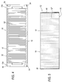
- the panel 10 as may be inferred also from Figure 4 , comprises a panel body 12 which is made mainly of concrete reinforced with metal bars and which has a front face 12' and a rear face 12", illustrated in Figure 5 , where the front face 12' comprises a plurality of protruding surfaces constituting means for providing a soundproofing effect.
- the panel has a top face 16, a bottom face 18 and opposite lateral end portions 12a, 12a extending between corresponding transversal portions, or flanges 13a, 13a of the panel supporting means 13, as illustrated in Figure 1 , where the reference numeral 13b denotes the perpendicular core of the profile section 13, connecting the flanges 13a, 13a.
- interposed means or elements 30 are provided between the panel 10 and an opposite transversal portion 13a of the supporting means 13, said interposed or compensation means 30 extending perpendicularly relative to the front surface 12' of the panel and engage the opposite transversal portion 13a of the supporting means 13, as may be inferred from Figure 1 .
- the interposed means 30 comprise a first plug , or base plug 32 for engaging the respective panel 10 and a second, superposed plug 34 for fastening or connecting to the first plug 32 in order to create a longer perpendicular interposed element 30 suitable for engaging a profile section with a longer than standard perpendicular core 13b.
- this embodiment of the interposed means 30 also comprises a third, superposed plug 36 designed to be placed over the second plug 34 in order to further extend the length of the perpendicular interposed means 30 to engage the respective flange 13a of the profile section.
- Means are advantageously provided for fastening the plug 34 or 36 to the plug 32 or 34 below it, said means being embodied by respective rod-like means, in particular in the form of a plurality of perpendicular screws provided at the corners of the respective plug.
- the plugs are provided with matching sockets or holes, 33', 33", 33 for receiving respective screws or rod-like elements, not illustrated in detail in the drawings.
- the means for fastening the plug below comprise bush means or holes 33 for receiving respective rod-like means or screws which, as illustrated, extend from the body of the plug to provide means for insertion into respective bush means in the plug below.
- the bush means 33 have a first, wide stretch 33a and a second, narrow stretch 33b, having a cylindrical inside surface 33'b constituting means for engaging the circumferential peripheral surface of the fastening rod, and a cylindrical outside surface 33"b designed to engage the wide cylindrical surface of the bush in which it is inserted.
- the perpendicular bushes 33' have a large diameter, like the matching holes 33".
- each plug is made of plastic material by moulding and has a base layer or wall 30a, from which there extends in criss-cross fashion a plurality of lateral and intermediate walls, the peripheral or lateral walls being labelled 30b, and the intermediate walls or ribs being labelled 30c.
- the internal ribs constitute means for reinforcing the structure of the plug.
- the panel 10 has internal reinforcement of steel rods or rod meshing, denoted in its entirety by the reference numeral 18'.
- the reinforcement 18' is embedded in a concrete casting having suitable properties and quadrangular outside profile.
- the panel 10 is provided with a socket or housing 54 for accommodating the base plug 32.
- the socket or housing 54 is in the form of a shaped recess having a perpendicular, or horizontal edge, 54a, on the side of the recess extending towards the median or inner part of the panel, a pair of lateral or perpendicular surfaces 54b and 54c and a rear, or bottom, transversal surface with an end portion 54d leading to the respective upper or lower panel edge 16 or 18, and inclined slightly towards the front of the panel, and a part 54e that is substantially parallel to the front and rear transversal faces of the panel.
- the prismatic plug 32 is inserted into said recess or socket 54 and has a tab 32' protruding perpendicularly from an end wall 30b, said tab being positioned at the respective upper or lower edge 16 or 18 of the panel to be tightened and retained by the panel or other part positioned above or below.
- the shaped part of the front face 12' of the panel 10 occupies a wide central zone of the latter, excluding its peripheral and lateral strips 12a, 12a where the respective housing sockets 54 are located.
- sockets 54 provided at respective lateral, upper and lower zones of the panel 10.
- the interposed means may, depending on requirements, comprise a single plug 32, or any desired number of plugs, even higher than the three plugs 32, 34, 36 illustrated here.
- the plugs 32, 34, 36 may differ in thickness or height, to enable these modular means to be used in a wide range of working conditions.
- the plugs 32, 34, 36 constitute a set of plugs that can be conveniently connected to each other.
- the set of plugs might comprise a larger number of plugs and include plugs of any thickness.
- elastic means or elements 40 are advantageously provided for abutting one face, in particular a rear face 12" of the panel 10, against a facing rear transversal portion or flange 13a of the supporting means 13.
- the elastic abutment means 40 extend perpendicularly to the panel 10 from the transversal face 12" opposite that where the interposed means 30 extend.
- the abutment means 40 extend vertically for substantially the full height of the panel 10 and are located at a respective lateral zone 12a, 12a of the panel 10.
- the abutment means 40 are in the form of a longitudinally hollow element having a flat portion 41 which abuts the rear face 12" of the panel 10, and an arcuate portion 43 which extends from the flat portion 41 and which is designed to engage the respective flange 13a of the means for engaging the panel 10 supporting means.
- the arcuate engagement portion 43 forms, with the flat layer 41, a longitudinal cavity 44, into which a galvanized plate 45 can be conveniently inserted and then pulled out after the concrete has hardened sufficiently, that is to say, removed after the panel 10 has been made.
- the elastic abutment 40 of the panel 10 to the respective supporting profile section 13 comprises panel fastening means, which comprise a respective perpendicular tab 42 that extends from the flat portion 41 of the abutment element 40 and is designed to be inserted into the panel body.
- the tab 42 extends from the centre of the flat layer 41 and has an enlarged, pointed end portion 42a.
- a vertically elongated elastic element comprises a flat layer or surface 141 for abutting the rear face 12" of the panel 10, from which there extends a portion, labelled 143 in its entirety, and which in turn comprises a flat portion 143a for engaging the respective rear flange 13a of the supporting profile section 13, and respective perpendicular portions 143b, 143c for connection to the portion 143 to the base portion 141.
- the second embodiment of the abutment element 140 has a central cavity 144, included between the protruding element 143 and the flat layer 141, but smaller than the one of the first preferred embodiment.
- the perpendicular portions 143b, 143c extending from the engagement layer 140 provide, with the engagement portion 143a, an element for flexibly engaging the respective profile section 13.
- means are provided for engaging the body of the panel 10, which are inserted in the panel body and comprise, in particular a first and a second tab 142a, 142b extending from the lateral ends of the engagement layer 141.
- the lateral insertion tabs 142a, 142b comprise a respective portion 146a, 146b that extends parallel to the rear engagement face of the panel 12".
- the portions 146a, 146b parallel to the rear face 12" of the panel 10 extend towards each other from the perpendicular portions 147a, 147b of the flat layer 141.
- the tabs 146a, 146b are fastened to a plate 148 embedded in the concrete by means of perpendicular rods or screws 149, 149 inserted into the base 141 when the concrete is still fresh.
- both the abutment seals 40, 140 are made of an elastic material, preferably EPDM.
- Figures 17 to 20 illustrate a second embodiment 111 of the barrier which is not part of the invention.
- the panel 10 used in the second embodiment is similar to that of the first preferred embodiment.
- the components of the second embodiment that are similar to those of the first embodiment are denoted by the same reference numerals and for convenience and brevity are not commented again in detail.
- the second embodiment of the barrier comprises adjustable interposed or compensation means in the form of a rod-like element 131 protruding from a bush 132, that is inserted, or embedded, in the panel body, the bush 132 being open at the front end and having a cylindrical inside surface for engaging the outside surface of the rod 131.
- the cylindrical inside surface of the bush 132 giving onto the front surface of the panel is provided with threading that cooperates with a similar threading provided on the outside cylindrical surface of the protruding rod or screw 131.
- the bush 132 is situated and gives onto the flat inside face 54e of the socket 54.
- means are provided for reinforcing the concrete panel and comprising at least one outside layer 118a and an inside layer 118b comprising metal rods or meshing.
- the interposed means advantageously comprise a rod-like element 131, which terminates with an enlarged head 143' forming an abutment shoe having an engagement or contact layer 145 of suitable elastic material.
- the shoe 143' profile is flared towards the free engagement end 145 so as to form a wide engagement surface larger in diameter than the bush and the respective shoe rod.
- the shoe 143' is connected to the rod 131 by an articulated connection comprising hinge means enabling it to be positioned at any desired angle to the rod 131. This avoids unwanted flexural stresses between the shoe, or enlarged head, and the rod.
- the articulated means are not illustrated in detail in the drawings.
- Means might also be provided for locking the rod 131 in the extended engaged condition, said locking means being in particular in the form of a hexagonal nut 158 and comprising a cylindrical inside surface which is threaded and which cooperates with the outside threading of the rod 131. As illustrated, the nut 158 engages a respective washer 159.
- interposed means 130 advantageously comprise a distribution element 133 that is connected to the rod 131 through the lock nut 158 and abutting against the corresponding front face 54e of the panel 10 through respective interposed elastic means 134.
- the interposed means of the second embodiment comprise an elastic plate 134, preferably of EPDM, which engages the front face 54e of the socket 54 and which abuts the quadrangular metal plate 133 upon which the lock nut 158 operates.
- an elastic plate 134 preferably of EPDM, which engages the front face 54e of the socket 54 and which abuts the quadrangular metal plate 133 upon which the lock nut 158 operates.
- the metal plate 133 constitutes means for locking the elastic plate 134 against the front face 54e of the socket 54.
- the EPDM layer 134 and the metal lock plate 133 have holes 133' and 134' in the middle of them through which the rod 131 can pass.
- Figures 21 to 23 illustrate a third embodiment 211 of the barrier, which is not part of the invention.
- the third embodiment of the barrier uses a panel 10 similar to those of the embodiments described above and comprises interposed means or elements 230 similar to those of the second embodiment, including an extension screw 231 that fits into a corresponding threaded bush 132 and a distribution element 133 connected to the rod 131 through the lock nut 158 that abuts against the corresponding front face 54e of the panel 10 through respective interposed elastic means 134.
- the third embodiment differs from the second embodiment in that its interposed means 230 comprise a rod 231 having a large head 243 that is connected as one to, or made as a single part with, the rod 231.
- the EPDM layer 134 and the metal plate 133 have holes in the middle of them through which the rod 231 can pass.
- Figures 24 to 26 illustrate a fourth embodiment 311 of the barrier not part of the invention.
- the fourth embodiment of the barrier uses a panel 10 similar to those of the embodiments described above and comprises interposed means or elements 330 similar to those of the second embodiment, including an extension screw 331 that fits into a corresponding threaded bush 132, the interposed means 330 advantageously comprising a distribution element 333 connected to the rod 331 and abutting against the corresponding front face 54e of the panel 10 through respective interposed elastic means 334a.
- the fourth embodiment differs from the third embodiment in that its interposed means 330 comprise a rod 331 with a wide, thin head 343 which is integral with the rod 331 and which is recessed in a respective outer, or front layer 334b of elastic material preferably on the form of a layer of EPDM.
- the fourth embodiment comprises a metal plate 333 that is thicker than the equivalent metal plate of the second and third embodiments described above, the metal plate 333 being held in place between a first and a second layer 334a, 334b of EPDM.
- transversal strip 334b of the elastic element is placed over the head 343 of the rod 331 or might have a large central cavity allowing the head 343 of the rod 331 to be accommodated under the outside or front face 334'b of the elastic layer 334b.
- the front face 334'b of the elastic layer 334b constitutes means for engaging the opposing transversal flange 13a of the profile section 13.
- the EPDM layer 334a which engages the socket 54, and the metal plate 333 have holes in the middle of them through which the rod or screw 331 can pass.
Landscapes
- Engineering & Computer Science (AREA)
- Architecture (AREA)
- Civil Engineering (AREA)
- Structural Engineering (AREA)
- Life Sciences & Earth Sciences (AREA)
- Sustainable Development (AREA)
- Connection Of Plates (AREA)
- Containers Having Bodies Formed In One Piece (AREA)
- Fencing (AREA)
- Refuge Islands, Traffic Blockers, Or Guard Fence (AREA)
Description
- This invention relates to a barrier used, in particular, in the sector of infrastructures or of constructions in general.
- More specifically, the barrier can be used in any construction or is preferably erected alongside lines of communication such as roads, motorways and railways, in particular to isolate them acoustically from the surrounding environment.
- Barriers comprising soundproofing panels are known in the prior art in this field. The panels are mounted on H profile sections made of metal by inserting a lateral portion of the panel between the flanges of the profile section and fastening it to the profile section using a plug made of an elastic material. The plug does not, however, allow fastening if the thickness of the profile sections is much greater than the thickness of the panel the elastic plug is associated with.
- In other prior art barriers, the interposed means for connection to the supporting profile section are in the form of screw fastening means inserted in a bush embedded in the panel. The screw holds the panel thanks to a lock nut which, however, abuts directly against the panel concrete, creating an area of excessive stress, with all the problems that this involves, especially when the structure is exposed to states of intense vibration. In particular, the fastening screw tends to come loose, eventually leading to unwanted slackening of the structure.
-
US 5 572 847 A discloses a barrier having the features of the preamble of claim 1. - It is provided a barrier according to claim 1.
- The panel can easily be fastened to the profile sections, or supporting means, whatever the geometry of the supporting means themselves.
- Further, operators responsible for mounting the panel on the supporting means can act directly on the interposed means after positioning the panel at the supporting means.
- This greatly facilitates barrier panel erection on site and is well suited to panel supporting means of any size.
- The technical characteristics of the barrier according to the invention are clearly described in the appended claims and the advantages are more apparent from the detailed description which follows, with reference to the accompanying drawings, which illustrate non-limiting examples of embodiments of the invention and in which:
-
Figure 1 is a schematic perspective view of a detail of a first preferred embodiment of the barrier according to the invention, mounting a first preferred embodiment of interposed means for engaging the panel to the respective supporting upright; -
Figure 2 is a schematic perspective view of a detail of apanel 10 with a respective interposed element; -
Figure 3 is an exploded perspective view of the detail ofFigure 2 ; -
Figure 4 is a schematic front view showing only thepanel 10 of the first preferred embodiment; -
Figure 5 is a schematic rear view showing only the panel of the first preferred embodiment of the barrier; -
Figure 6 is a schematic rear view showing the first plug of the first preferred embodiment of the interposed means; -
Figure 7 is schematic cross section through the line A1-A1 ofFigure 6 showing the first plug constituting the first embodiment of the interposed means; -
Figure 8 is a schematic horizontal cross section through the line A-A ofFigure 6 showing the first plug constituting the first preferred embodiment of the interposed means; -
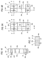
Figures 9A and 9B are schematic rear views respectively showing the second and third plugs of the first preferred embodiment of the interposed means; -
Figure 10 is a schematic cross section through the line B1-B1 ofFigure 9A showing the second plug; -
Figure 11 is a schematic cross section through the line B-B ofFigure 9A showing the second plug; -
Figure 12 is a cross section similar to that ofFigure 10 , through the line B1-B1 ofFigure 9B , showing a third plug of the first preferred embodiment of the interposed means; -
Figure 13 is a cross section similar to that ofFigure 11 , through the line B-B ofFigure 9B , showing the third plug of the first preferred embodiment of the interposed means; -
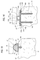
Figure 14 is a vertical cross section of the zone where the interposed means are positioned on the respective panel, showing in particular the internal reinforcement at that zone; -
Figure 15 is a horizontal cross section of a side, rear zone of the panel, in particular illustrating means for abutting or engaging the back of the panel to the transversal flange of the supporting means, said means not being part of the invention; -
Figure 16 shows a second embodiment of the abutment means in a cross section similar to that ofFigure 15 , said embodiment not being part of the invention; -
Figure 17 is a schematic perspective view similar to that ofFigure 1 , showing a second embodiment of the interposed means, this embodiment not being part of the invention; -
Figure 18 is a schematic perspective view similar to that ofFigure 2 , showing a panel mounting the second embodiment of the interposed means, this embodiment not being part of the invention; -
Figure 19 is a schematic exploded perspective view similar to that ofFigure 3 , illustrating the second embodiment of the interposed means between the panel and the supporting profile section, this embodiment not being part of the invention; -
Figure 20 is a vertical cross section similar to that ofFigure 14 , showing the extension zone of the interposed means and, in particular, the shape of the reinforcement at said zone, where the interposed means are housed in the panel, this embodiment not being part of the invention; -
Figures 21 to 23 are views similar to those ofFigures 1, 2 and 3 , illustrating a third embodiment of the barrier mounting a third embodiment of the interposed means, this embodiment not being part of the invention; -
Figures 24, 25 and 26 are views similar to those ofFigures 1, 2 and 3 , illustrating a fourth embodiment of the barrier mounting a fourth embodiment of the interposed means, this embodiment not being part of the invention. -
Figure 1 illustrates a detail of abarrier 11, designed in particular to be erected alongside lines of communication such as railways, roads, motorways and the like. The barrier comprises respective panels, of which only a portion, labelled 10, is illustrated inFigure 1 , and means 13 for supporting the panels, comprising preferably an H profile section made of metal and mounted vertically on a respective foundation which is not illustrated in the accompanying drawings and which may be of customary type well known to an expert in the trade. - The
panel 10, as may be inferred also fromFigure 4 , comprises apanel body 12 which is made mainly of concrete reinforced with metal bars and which has a front face 12' and arear face 12", illustrated inFigure 5 , where the front face 12' comprises a plurality of protruding surfaces constituting means for providing a soundproofing effect. - The panel has a
top face 16, abottom face 18 and oppositelateral end portions flanges Figure 1 , where thereference numeral 13b denotes the perpendicular core of theprofile section 13, connecting theflanges - As illustrated, interposed means or
elements 30 are provided between thepanel 10 and an oppositetransversal portion 13a of the supportingmeans 13, said interposed or compensation means 30 extending perpendicularly relative to the front surface 12' of the panel and engage the oppositetransversal portion 13a of the supportingmeans 13, as may be inferred fromFigure 1 . - According to the invention, the interposed
means 30 comprise a first plug , orbase plug 32 for engaging therespective panel 10 and a second, superposedplug 34 for fastening or connecting to thefirst plug 32 in order to create a longer perpendicular interposedelement 30 suitable for engaging a profile section with a longer than standardperpendicular core 13b. - As illustrated, this embodiment of the interposed
means 30 also comprises a third, superposedplug 36 designed to be placed over thesecond plug 34 in order to further extend the length of the perpendicular interposedmeans 30 to engage therespective flange 13a of the profile section. - It will be understood, however, that the interposed means used for narrower profile sections or thicker panels might comprise only the first and
second plugs - Means are advantageously provided for fastening the
plug plug - As illustrated, the plugs are provided with matching sockets or holes, 33', 33", 33 for receiving respective screws or rod-like elements, not illustrated in detail in the drawings.
- In particular, the means for fastening the plug below comprise bush means or
holes 33 for receiving respective rod-like means or screws which, as illustrated, extend from the body of the plug to provide means for insertion into respective bush means in the plug below. - In particular, as illustrated in the drawings of the
superposed plugs wide stretch 33a and a second,narrow stretch 33b, having a cylindrical inside surface 33'b constituting means for engaging the circumferential peripheral surface of the fastening rod, and a cylindricaloutside surface 33"b designed to engage the wide cylindrical surface of the bush in which it is inserted. - In the
base plug 32, the perpendicular bushes 33' have a large diameter, like the matchingholes 33". - Advantageously, each plug is made of plastic material by moulding and has a base layer or
wall 30a, from which there extends in criss-cross fashion a plurality of lateral and intermediate walls, the peripheral or lateral walls being labelled 30b, and the intermediate walls or ribs being labelled 30c. The internal ribs constitute means for reinforcing the structure of the plug. - As may be inferred in particular from
Figure 14 , thepanel 10 has internal reinforcement of steel rods or rod meshing, denoted in its entirety by the reference numeral 18'. - In particular, as illustrated, there is at least one
outside layer 18a and one insidelayer 18b of reinforcement rods. The reinforcement 18' is embedded in a concrete casting having suitable properties and quadrangular outside profile. - According to the invention, the
panel 10 is provided with a socket orhousing 54 for accommodating thebase plug 32. - The socket or
housing 54 is in the form of a shaped recess having a perpendicular, or horizontal edge, 54a, on the side of the recess extending towards the median or inner part of the panel, a pair of lateral orperpendicular surfaces end portion 54d leading to the respective upper orlower panel edge part 54e that is substantially parallel to the front and rear transversal faces of the panel. - As illustrated, in use, the
prismatic plug 32, is inserted into said recess orsocket 54 and has a tab 32' protruding perpendicularly from anend wall 30b, said tab being positioned at the respective upper orlower edge - As illustrated, the shaped part of the front face 12' of the
panel 10 occupies a wide central zone of the latter, excluding its peripheral andlateral strips respective housing sockets 54 are located. - In particular, there is a plurality of
sockets 54 provided at respective lateral, upper and lower zones of thepanel 10. - In practice, modular interposed means are thus provided. In effect, the interposed means may, depending on requirements, comprise a
single plug 32, or any desired number of plugs, even higher than the threeplugs - Further, as illustrated here, the
plugs - In other terms, the
plugs - As may be inferred in particular from
Figures 5 ,14 and15 , elastic means orelements 40 are advantageously provided for abutting one face, in particular arear face 12" of thepanel 10, against a facing rear transversal portion orflange 13a of the supportingmeans 13. - As illustrated, the elastic abutment means 40 extend perpendicularly to the
panel 10 from thetransversal face 12" opposite that where the interposed means 30 extend. - As illustrated, the abutment means 40 extend vertically for substantially the full height of the
panel 10 and are located at arespective lateral zone panel 10. - As may be well inferred from
Figure 15 , the abutment means 40 are in the form of a longitudinally hollow element having aflat portion 41 which abuts therear face 12" of thepanel 10, and anarcuate portion 43 which extends from theflat portion 41 and which is designed to engage therespective flange 13a of the means for engaging thepanel 10 supporting means. - In particular, the
arcuate engagement portion 43 forms, with theflat layer 41, alongitudinal cavity 44, into which a galvanizedplate 45 can be conveniently inserted and then pulled out after the concrete has hardened sufficiently, that is to say, removed after thepanel 10 has been made. - As illustrated, the
elastic abutment 40 of thepanel 10 to the respective supportingprofile section 13 comprises panel fastening means, which comprise a respectiveperpendicular tab 42 that extends from theflat portion 41 of theabutment element 40 and is designed to be inserted into the panel body. - The
tab 42 extends from the centre of theflat layer 41 and has an enlarged, pointedend portion 42a. - According to a
second embodiment 140 of the rear abutment means or elements, illustrated inFigure 16 , but not part of the invention, a vertically elongated elastic element comprises a flat layer orsurface 141 for abutting therear face 12" of thepanel 10, from which there extends a portion, labelled 143 in its entirety, and which in turn comprises aflat portion 143a for engaging the respectiverear flange 13a of the supportingprofile section 13, and respectiveperpendicular portions portion 143 to thebase portion 141. - Thus, also the second embodiment of the
abutment element 140 has acentral cavity 144, included between theprotruding element 143 and theflat layer 141, but smaller than the one of the first preferred embodiment. - In practice, the
perpendicular portions engagement layer 140 provide, with theengagement portion 143a, an element for flexibly engaging therespective profile section 13. - In the second embodiment, too, means are provided for engaging the body of the
panel 10, which are inserted in the panel body and comprise, in particular a first and asecond tab engagement layer 141. - The
lateral insertion tabs respective portion panel 12". - More specifically, the
portions rear face 12" of thepanel 10 extend towards each other from theperpendicular portions flat layer 141. - The
tabs plate 148 embedded in the concrete by means of perpendicular rods or screws 149, 149 inserted into the base 141 when the concrete is still fresh. - Advantageously, both the abutment seals 40, 140 are made of an elastic material, preferably EPDM.
-
Figures 17 to 20 illustrate asecond embodiment 111 of the barrier which is not part of the invention. - The
panel 10 used in the second embodiment is similar to that of the first preferred embodiment. The components of the second embodiment that are similar to those of the first embodiment are denoted by the same reference numerals and for convenience and brevity are not commented again in detail. - The second embodiment of the barrier comprises adjustable interposed or compensation means in the form of a rod-
like element 131 protruding from abush 132, that is inserted, or embedded, in the panel body, thebush 132 being open at the front end and having a cylindrical inside surface for engaging the outside surface of therod 131. - In particular, the cylindrical inside surface of the
bush 132 giving onto the front surface of the panel is provided with threading that cooperates with a similar threading provided on the outside cylindrical surface of the protruding rod orscrew 131. - Advantageously, the
bush 132 is situated and gives onto the flatinside face 54e of thesocket 54. - In the second embodiment, too, as illustrated in
Figure 20 , means are provided for reinforcing the concrete panel and comprising at least oneoutside layer 118a and aninside layer 118b comprising metal rods or meshing. - In practice, as illustrated, the interposed means advantageously comprise a rod-
like element 131, which terminates with an enlarged head 143' forming an abutment shoe having an engagement orcontact layer 145 of suitable elastic material. - As illustrated, the shoe 143' profile is flared towards the
free engagement end 145 so as to form a wide engagement surface larger in diameter than the bush and the respective shoe rod. - The shoe 143' is connected to the
rod 131 by an articulated connection comprising hinge means enabling it to be positioned at any desired angle to therod 131. This avoids unwanted flexural stresses between the shoe, or enlarged head, and the rod. The articulated means are not illustrated in detail in the drawings. - Means might also be provided for locking the
rod 131 in the extended engaged condition, said locking means being in particular in the form of ahexagonal nut 158 and comprising a cylindrical inside surface which is threaded and which cooperates with the outside threading of therod 131. As illustrated, thenut 158 engages arespective washer 159. - Further, the interposed means 130 advantageously comprise a
distribution element 133 that is connected to therod 131 through thelock nut 158 and abutting against the correspondingfront face 54e of thepanel 10 through respective interposedelastic means 134. - For the purpose, the interposed means of the second embodiment comprise an
elastic plate 134, preferably of EPDM, which engages thefront face 54e of thesocket 54 and which abuts thequadrangular metal plate 133 upon which thelock nut 158 operates. In this way, the stresses are conveniently distributed, avoiding breakage of the concrete and slackening of the connection. - The
metal plate 133 constitutes means for locking theelastic plate 134 against thefront face 54e of thesocket 54. - As illustrated, the
EPDM layer 134 and themetal lock plate 133 have holes 133' and 134' in the middle of them through which therod 131 can pass. -
Figures 21 to 23 illustrate athird embodiment 211 of the barrier, which is not part of the invention. - The third embodiment of the barrier uses a
panel 10 similar to those of the embodiments described above and comprises interposed means orelements 230 similar to those of the second embodiment, including anextension screw 231 that fits into a corresponding threadedbush 132 and adistribution element 133 connected to therod 131 through thelock nut 158 that abuts against the correspondingfront face 54e of thepanel 10 through respective interposedelastic means 134. - In this case, too, the components of the third embodiment that are similar to those of the other embodiments already described are denoted by the same reference numerals and for convenience and brevity are not commented again in detail.
- The third embodiment differs from the second embodiment in that its interposed means 230 comprise a
rod 231 having alarge head 243 that is connected as one to, or made as a single part with, therod 231. - A
cap 245, made of an elastic material, preferably rubber, is also provided for covering thelarge head 243 of thescrew 231. - In the third embodiment, too, the
EPDM layer 134 and themetal plate 133 have holes in the middle of them through which therod 231 can pass. -
Figures 24 to 26 illustrate afourth embodiment 311 of the barrier not part of the invention. - The fourth embodiment of the barrier uses a
panel 10 similar to those of the embodiments described above and comprises interposed means orelements 330 similar to those of the second embodiment, including anextension screw 331 that fits into a corresponding threadedbush 132, the interposed means 330 advantageously comprising adistribution element 333 connected to therod 331 and abutting against the correspondingfront face 54e of thepanel 10 through respective interposedelastic means 334a. - In this case, too, the components of the fourth embodiment that are similar to those of the other embodiments already described are denoted by the same reference numerals and for convenience and brevity are not commented again in detail.
- The fourth embodiment differs from the third embodiment in that its interposed means 330 comprise a
rod 331 with a wide,thin head 343 which is integral with therod 331 and which is recessed in a respective outer, orfront layer 334b of elastic material preferably on the form of a layer of EPDM. - In practice, as illustrated, the fourth embodiment comprises a
metal plate 333 that is thicker than the equivalent metal plate of the second and third embodiments described above, themetal plate 333 being held in place between a first and asecond layer - In particular, there is a single
elastic element 334 with a first and a secondtransversal strip perpendicular portion 334c. - Further, the
transversal strip 334b of the elastic element is placed over thehead 343 of therod 331 or might have a large central cavity allowing thehead 343 of therod 331 to be accommodated under the outside or front face 334'b of theelastic layer 334b. - As illustrated, the front face 334'b of the
elastic layer 334b constitutes means for engaging the opposingtransversal flange 13a of theprofile section 13. - In the fourth embodiment, too, the
EPDM layer 334a, which engages thesocket 54, and themetal plate 333 have holes in the middle of them through which the rod or screw 331 can pass. - The invention described above is susceptible of industrial application and may be modified and adapted in several ways as defined in the appended claims.
Claims (15)
- A barrier (11) comprising respective panels (10) and means (13) for supporting the panels, each panel (10) having a panel body (12) with a top face (16) and a bottom face (18), transversal front (12') and rear (12") faces, and opposite lateral end portions (12a, 12a) extending between corresponding transversal portions (13a, 13a) of the panel supporting means; interposed means (30) being provided between the panel (10) and a transversal portion (13a) of the supporting means (13) facing the panel (10), said interposed means (30) extending perpendicularly to the panel and engaging said transversal portion (13a) of the supporting means (13); the interposed means (30) comprising a first plug (32) for engaging the respective panel (10) and a second, superposed plug (34) placed over the first plug (32); the first plug (32) being accommodated in a corresponding housing (54) in the panel (10) that is recessed relative to a transversal face (12'; 12") of the panel (10); characterized in that the first plug (32) comprises a protruding tab (32') constituting means for fastening the first plug (32) to the panel; the tab (32') protruding perpendicularly to a base wall (30a) and from a peripheral wall (30b) of the first plug and being positioned at the respective top or bottom face (16 or 18) of the panel to be tightened and retained by the panel or other part positioned above or below.
- The barrier according to claim 1, characterized in that the interposed means (30) comprise a third plug (36) for superposing the second plug (34).
- The barrier according to either of the foregoing claims, characterized in that it comprises means for fastening the plug (34; 36) to the plug (32; 34) below it.
- The barrier according to claim 3, characterized in that the means for fastening the plug below (32; 34) comprise respective rod-like means.
- The barrier according to claim 3 or 4, characterized in that the means for fastening the plug below (32; 34) comprise a plurality of perpendicular rods at the corners of the plug.
- The barrier according to any of the foregoing claims from 3 to 5, characterized in that the means for fastening the plug below (32; 34) are in the form of respective screw means.
- The barrier according to any of the foregoing claims from 3 to 6, characterized in that the means for fastening the plug below (32; 34) comprise bush means (33) for receiving respective rod-like means.
- The barrier according to claim 7, characterized in that the bush means (33) extend from the plug body, constituting means for insertion into respective bush means (33) on the plug below (32; 34).
- The barrier according to claim 7 or 8, characterized in that the bush means (33) have a wide first section (33a) for receiving a corresponding bush and a narrower second section (33b), constituting means for engaging the rod.
- The barrier according to any of the foregoing claims, characterized in that each plug (32, 34, 36) is made of a plastic material.
- The barrier according to any of the foregoing claims, characterized in that each plug (32, 34, 36) is in the form of a moulded element.
- The barrier according to any of the foregoing claims, characterized in that each plug (32, 34, 36) has a transversal base wall (30a) and a plurality of perpendicular walls (30b, 30c).
- The barrier according to any of the foregoing claims, characterized in that each plug (32, 34, 36) has a plurality of internal reinforcement ribs (30c).
- The barrier according to any of the foregoing claims, characterized in that the housing (54) is in the form of a shaped recess having a perpendicular, or horizontal edge, (54a), on the side of the recess extending towards the median or inner part of the panel, a pair of lateral or perpendicular surfaces (54b and 54c) and a rear, or bottom, transversal surface with an end portion (54d) leading to the respective upper or lower panel edge (16 or 18), and inclined slightly towards the front of the panel, and a part (54e) that is substantially parallel to the front and rear transversal faces (12', 12") of the panel.
- The barrier according to any of the foregoing claims, characterized in that it comprises elastic abutment means (40) allowing a face, in particular a rear face (12"), of the panel (10) to be placed against an opposing transversal portion (13a) of the supporting means (13).
Applications Claiming Priority (2)
| Application Number | Priority Date | Filing Date | Title |
|---|---|---|---|
| ITBO2008A000517A IT1391533B1 (en) | 2008-08-08 | 2008-08-08 | PERFECT BARRIER. |
| PCT/IB2009/053402 WO2010016013A1 (en) | 2008-08-08 | 2009-08-05 | Improved barrier |
Publications (2)
| Publication Number | Publication Date |
|---|---|
| EP2318592A1 EP2318592A1 (en) | 2011-05-11 |
| EP2318592B1 true EP2318592B1 (en) | 2016-08-03 |
Family
ID=40532513
Family Applications (1)
| Application Number | Title | Priority Date | Filing Date |
|---|---|---|---|
| EP09804635.2A Not-in-force EP2318592B1 (en) | 2008-08-08 | 2009-08-05 | Improved barrier |
Country Status (4)
| Country | Link |
|---|---|
| EP (1) | EP2318592B1 (en) |
| IT (1) | IT1391533B1 (en) |
| RU (1) | RU2514289C2 (en) |
| WO (1) | WO2010016013A1 (en) |
Family Cites Families (9)
| Publication number | Priority date | Publication date | Assignee | Title |
|---|---|---|---|---|
| DE3030931A1 (en) * | 1980-08-16 | 1982-04-01 | Ed. Züblin AG, 7000 Stuttgart | Noise screen wall concrete slab mounting on posts - involves right angled side screw bolts with protruding heads, permitting adjustment |
| DE8524319U1 (en) * | 1985-08-24 | 1985-10-10 | Röhm GmbH, 6100 Darmstadt | Glazing bar |
| US5572847A (en) * | 1992-08-28 | 1996-11-12 | Jte, Inc. | Rapidly erectable, removable, reusable and raisable outdoor acoustical wall system |
| US5467567A (en) * | 1992-12-29 | 1995-11-21 | The Reinforced Earth Company | Spring biased apparatus for maintaining precast panels in a stable removable position in a vertical slot |
| FR2734586B1 (en) * | 1995-05-24 | 1997-07-25 | Hutchinson | ACOUSTIC SCREEN SUPPORT ALONG A VEHICLE TRAVEL PATH |
| AT404147B (en) * | 1996-07-30 | 1998-08-25 | Porr Allg Bauges | SOUND PROTECTIVE WALL FOR INSULATING SOUND EMISSIONS FROM TRANSPORT |
| RU2151839C1 (en) * | 1999-02-24 | 2000-06-27 | Суханов Александр Викторович | Roadside noise shield (versions) |
| DE19934810B4 (en) * | 1999-07-29 | 2005-05-04 | Spig Schutzplanken-Produktions-Gesellschaft Mbh & Co Kg | Noise barrier next to driveways |
| RU49834U1 (en) * | 2004-11-04 | 2005-12-10 | Бонгард Гмбх Унд Ко.Кг | NOISE PROTECTIVE ELEMENT AND NOISE PROTECTIVE SCREEN |
-
2008
- 2008-08-08 IT ITBO2008A000517A patent/IT1391533B1/en active
-
2009
- 2009-08-05 EP EP09804635.2A patent/EP2318592B1/en not_active Not-in-force
- 2009-08-05 RU RU2011126535/03A patent/RU2514289C2/en not_active IP Right Cessation
- 2009-08-05 WO PCT/IB2009/053402 patent/WO2010016013A1/en not_active Ceased
Also Published As
| Publication number | Publication date |
|---|---|
| RU2514289C2 (en) | 2014-04-27 |
| EP2318592A1 (en) | 2011-05-11 |
| ITBO20080517A1 (en) | 2010-02-09 |
| IT1391533B1 (en) | 2012-01-11 |
| WO2010016013A1 (en) | 2010-02-11 |
| RU2011126535A (en) | 2013-01-10 |
Similar Documents
| Publication | Publication Date | Title |
|---|---|---|
| EP0302046B1 (en) | Arrangement for a partition element | |
| CA2204272A1 (en) | Foam block wall and fabrication method | |
| WO2008046177A1 (en) | Wall opening form | |
| CN1283882C (en) | Sound barrier | |
| WO2008092664A2 (en) | Construction element | |
| KR200358585Y1 (en) | A fixing apparatus for building decoration plate stone | |
| US7121045B2 (en) | Pre-hanging clip for pre-hung door | |
| EP2093362B1 (en) | Method and clamping system for the fixation of a hinge or other metal work on profiles for windows and doors | |
| WO2010016013A1 (en) | Improved barrier | |
| EP2321465A1 (en) | Antinoise barrier | |
| US8763317B2 (en) | Concrete roof panel | |
| RU29737U1 (en) | Building module | |
| KR200325599Y1 (en) | Prefabricated building using container box | |
| KR200381862Y1 (en) | Outside Reinforcement Structure of Fabricated Water Tank | |
| KR100769336B1 (en) | Partition panel | |
| KR100437261B1 (en) | steel pipe pile head reinforcement structure | |
| CN1737319A (en) | Door stop type doorframe structure made of synthetic resin material | |
| KR100209170B1 (en) | Structure of the fireproof doors | |
| KR200259836Y1 (en) | The case of a deposit control panel | |
| KR200267890Y1 (en) | Support for a reinforcing member of building forms | |
| WO2008029962A1 (en) | A spacer having an anchor bolt mounting portion thereon | |
| KR200420288Y1 (en) | Composite beam with improved stiffness | |
| CN215718005U (en) | Hinge installation component and engineering machine | |
| KR200322796Y1 (en) | a frame for a window | |
| KR200315814Y1 (en) | Slab support structure of bridge using steel box |
Legal Events
| Date | Code | Title | Description |
|---|---|---|---|
| PUAI | Public reference made under article 153(3) epc to a published international application that has entered the european phase |
Free format text: ORIGINAL CODE: 0009012 |
|
| 17P | Request for examination filed |
Effective date: 20110218 |
|
| AK | Designated contracting states |
Kind code of ref document: A1 Designated state(s): AT BE BG CH CY CZ DE DK EE ES FI FR GB GR HR HU IE IS IT LI LT LU LV MC MK MT NL NO PL PT RO SE SI SK SM TR |
|
| AX | Request for extension of the european patent |
Extension state: AL BA RS |
|
| DAX | Request for extension of the european patent (deleted) | ||
| GRAP | Despatch of communication of intention to grant a patent |
Free format text: ORIGINAL CODE: EPIDOSNIGR1 |
|
| INTG | Intention to grant announced |
Effective date: 20160203 |
|
| GRAS | Grant fee paid |
Free format text: ORIGINAL CODE: EPIDOSNIGR3 |
|
| GRAA | (expected) grant |
Free format text: ORIGINAL CODE: 0009210 |
|
| AK | Designated contracting states |
Kind code of ref document: B1 Designated state(s): AT BE BG CH CY CZ DE DK EE ES FI FR GB GR HR HU IE IS IT LI LT LU LV MC MK MT NL NO PL PT RO SE SI SK SM TR |
|
| REG | Reference to a national code |
Ref country code: GB Ref legal event code: FG4D |
|
| REG | Reference to a national code |
Ref country code: CH Ref legal event code: EP Ref country code: AT Ref legal event code: REF Ref document number: 817428 Country of ref document: AT Kind code of ref document: T Effective date: 20160815 |
|
| REG | Reference to a national code |
Ref country code: IE Ref legal event code: FG4D |
|
| REG | Reference to a national code |
Ref country code: DE Ref legal event code: R096 Ref document number: 602009040133 Country of ref document: DE |
|
| REG | Reference to a national code |
Ref country code: NL Ref legal event code: MP Effective date: 20160803 |
|
| REG | Reference to a national code |
Ref country code: LT Ref legal event code: MG4D |
|
| REG | Reference to a national code |
Ref country code: AT Ref legal event code: MK05 Ref document number: 817428 Country of ref document: AT Kind code of ref document: T Effective date: 20160803 |
|
| PG25 | Lapsed in a contracting state [announced via postgrant information from national office to epo] |
Ref country code: HR Free format text: LAPSE BECAUSE OF FAILURE TO SUBMIT A TRANSLATION OF THE DESCRIPTION OR TO PAY THE FEE WITHIN THE PRESCRIBED TIME-LIMIT Effective date: 20160803 Ref country code: IS Free format text: LAPSE BECAUSE OF FAILURE TO SUBMIT A TRANSLATION OF THE DESCRIPTION OR TO PAY THE FEE WITHIN THE PRESCRIBED TIME-LIMIT Effective date: 20161203 Ref country code: NO Free format text: LAPSE BECAUSE OF FAILURE TO SUBMIT A TRANSLATION OF THE DESCRIPTION OR TO PAY THE FEE WITHIN THE PRESCRIBED TIME-LIMIT Effective date: 20161103 Ref country code: LT Free format text: LAPSE BECAUSE OF FAILURE TO SUBMIT A TRANSLATION OF THE DESCRIPTION OR TO PAY THE FEE WITHIN THE PRESCRIBED TIME-LIMIT Effective date: 20160803 Ref country code: NL Free format text: LAPSE BECAUSE OF FAILURE TO SUBMIT A TRANSLATION OF THE DESCRIPTION OR TO PAY THE FEE WITHIN THE PRESCRIBED TIME-LIMIT Effective date: 20160803 Ref country code: FI Free format text: LAPSE BECAUSE OF FAILURE TO SUBMIT A TRANSLATION OF THE DESCRIPTION OR TO PAY THE FEE WITHIN THE PRESCRIBED TIME-LIMIT Effective date: 20160803 Ref country code: IT Free format text: LAPSE BECAUSE OF FAILURE TO SUBMIT A TRANSLATION OF THE DESCRIPTION OR TO PAY THE FEE WITHIN THE PRESCRIBED TIME-LIMIT Effective date: 20160803 |
|
| PG25 | Lapsed in a contracting state [announced via postgrant information from national office to epo] |
Ref country code: LV Free format text: LAPSE BECAUSE OF FAILURE TO SUBMIT A TRANSLATION OF THE DESCRIPTION OR TO PAY THE FEE WITHIN THE PRESCRIBED TIME-LIMIT Effective date: 20160803 Ref country code: ES Free format text: LAPSE BECAUSE OF FAILURE TO SUBMIT A TRANSLATION OF THE DESCRIPTION OR TO PAY THE FEE WITHIN THE PRESCRIBED TIME-LIMIT Effective date: 20160803 Ref country code: GR Free format text: LAPSE BECAUSE OF FAILURE TO SUBMIT A TRANSLATION OF THE DESCRIPTION OR TO PAY THE FEE WITHIN THE PRESCRIBED TIME-LIMIT Effective date: 20161104 Ref country code: SE Free format text: LAPSE BECAUSE OF FAILURE TO SUBMIT A TRANSLATION OF THE DESCRIPTION OR TO PAY THE FEE WITHIN THE PRESCRIBED TIME-LIMIT Effective date: 20160803 Ref country code: PL Free format text: LAPSE BECAUSE OF FAILURE TO SUBMIT A TRANSLATION OF THE DESCRIPTION OR TO PAY THE FEE WITHIN THE PRESCRIBED TIME-LIMIT Effective date: 20160803 Ref country code: PT Free format text: LAPSE BECAUSE OF FAILURE TO SUBMIT A TRANSLATION OF THE DESCRIPTION OR TO PAY THE FEE WITHIN THE PRESCRIBED TIME-LIMIT Effective date: 20161205 Ref country code: BE Free format text: LAPSE BECAUSE OF NON-PAYMENT OF DUE FEES Effective date: 20160831 Ref country code: AT Free format text: LAPSE BECAUSE OF FAILURE TO SUBMIT A TRANSLATION OF THE DESCRIPTION OR TO PAY THE FEE WITHIN THE PRESCRIBED TIME-LIMIT Effective date: 20160803 |
|
| REG | Reference to a national code |
Ref country code: DE Ref legal event code: R119 Ref document number: 602009040133 Country of ref document: DE |
|
| REG | Reference to a national code |
Ref country code: CH Ref legal event code: PL |
|
| PG25 | Lapsed in a contracting state [announced via postgrant information from national office to epo] |
Ref country code: CH Free format text: LAPSE BECAUSE OF NON-PAYMENT OF DUE FEES Effective date: 20160831 Ref country code: LI Free format text: LAPSE BECAUSE OF NON-PAYMENT OF DUE FEES Effective date: 20160831 Ref country code: EE Free format text: LAPSE BECAUSE OF FAILURE TO SUBMIT A TRANSLATION OF THE DESCRIPTION OR TO PAY THE FEE WITHIN THE PRESCRIBED TIME-LIMIT Effective date: 20160803 Ref country code: RO Free format text: LAPSE BECAUSE OF FAILURE TO SUBMIT A TRANSLATION OF THE DESCRIPTION OR TO PAY THE FEE WITHIN THE PRESCRIBED TIME-LIMIT Effective date: 20160803 |
|
| PG25 | Lapsed in a contracting state [announced via postgrant information from national office to epo] |
Ref country code: CZ Free format text: LAPSE BECAUSE OF FAILURE TO SUBMIT A TRANSLATION OF THE DESCRIPTION OR TO PAY THE FEE WITHIN THE PRESCRIBED TIME-LIMIT Effective date: 20160803 Ref country code: SK Free format text: LAPSE BECAUSE OF FAILURE TO SUBMIT A TRANSLATION OF THE DESCRIPTION OR TO PAY THE FEE WITHIN THE PRESCRIBED TIME-LIMIT Effective date: 20160803 Ref country code: DK Free format text: LAPSE BECAUSE OF FAILURE TO SUBMIT A TRANSLATION OF THE DESCRIPTION OR TO PAY THE FEE WITHIN THE PRESCRIBED TIME-LIMIT Effective date: 20160803 Ref country code: BG Free format text: LAPSE BECAUSE OF FAILURE TO SUBMIT A TRANSLATION OF THE DESCRIPTION OR TO PAY THE FEE WITHIN THE PRESCRIBED TIME-LIMIT Effective date: 20161103 Ref country code: BE Free format text: LAPSE BECAUSE OF FAILURE TO SUBMIT A TRANSLATION OF THE DESCRIPTION OR TO PAY THE FEE WITHIN THE PRESCRIBED TIME-LIMIT Effective date: 20160803 Ref country code: SM Free format text: LAPSE BECAUSE OF FAILURE TO SUBMIT A TRANSLATION OF THE DESCRIPTION OR TO PAY THE FEE WITHIN THE PRESCRIBED TIME-LIMIT Effective date: 20160803 |
|
| REG | Reference to a national code |
Ref country code: IE Ref legal event code: MM4A |
|
| PLBE | No opposition filed within time limit |
Free format text: ORIGINAL CODE: 0009261 |
|
| STAA | Information on the status of an ep patent application or granted ep patent |
Free format text: STATUS: NO OPPOSITION FILED WITHIN TIME LIMIT |
|
| PG25 | Lapsed in a contracting state [announced via postgrant information from national office to epo] |
Ref country code: MC Free format text: LAPSE BECAUSE OF FAILURE TO SUBMIT A TRANSLATION OF THE DESCRIPTION OR TO PAY THE FEE WITHIN THE PRESCRIBED TIME-LIMIT Effective date: 20160803 |
|
| REG | Reference to a national code |
Ref country code: FR Ref legal event code: ST Effective date: 20170602 |
|
| 26N | No opposition filed |
Effective date: 20170504 |
|
| GBPC | Gb: european patent ceased through non-payment of renewal fee |
Effective date: 20161103 |
|
| PG25 | Lapsed in a contracting state [announced via postgrant information from national office to epo] |
Ref country code: FR Free format text: LAPSE BECAUSE OF NON-PAYMENT OF DUE FEES Effective date: 20161003 Ref country code: DE Free format text: LAPSE BECAUSE OF NON-PAYMENT OF DUE FEES Effective date: 20170301 Ref country code: IE Free format text: LAPSE BECAUSE OF NON-PAYMENT OF DUE FEES Effective date: 20160805 |
|
| PG25 | Lapsed in a contracting state [announced via postgrant information from national office to epo] |
Ref country code: SI Free format text: LAPSE BECAUSE OF FAILURE TO SUBMIT A TRANSLATION OF THE DESCRIPTION OR TO PAY THE FEE WITHIN THE PRESCRIBED TIME-LIMIT Effective date: 20160803 Ref country code: LU Free format text: LAPSE BECAUSE OF NON-PAYMENT OF DUE FEES Effective date: 20160805 |
|
| PG25 | Lapsed in a contracting state [announced via postgrant information from national office to epo] |
Ref country code: GB Free format text: LAPSE BECAUSE OF NON-PAYMENT OF DUE FEES Effective date: 20161103 |
|
| PG25 | Lapsed in a contracting state [announced via postgrant information from national office to epo] |
Ref country code: CY Free format text: LAPSE BECAUSE OF FAILURE TO SUBMIT A TRANSLATION OF THE DESCRIPTION OR TO PAY THE FEE WITHIN THE PRESCRIBED TIME-LIMIT Effective date: 20160803 Ref country code: HU Free format text: LAPSE BECAUSE OF FAILURE TO SUBMIT A TRANSLATION OF THE DESCRIPTION OR TO PAY THE FEE WITHIN THE PRESCRIBED TIME-LIMIT; INVALID AB INITIO Effective date: 20090805 |
|
| PG25 | Lapsed in a contracting state [announced via postgrant information from national office to epo] |
Ref country code: TR Free format text: LAPSE BECAUSE OF FAILURE TO SUBMIT A TRANSLATION OF THE DESCRIPTION OR TO PAY THE FEE WITHIN THE PRESCRIBED TIME-LIMIT Effective date: 20160803 Ref country code: MT Free format text: LAPSE BECAUSE OF NON-PAYMENT OF DUE FEES Effective date: 20160831 Ref country code: MK Free format text: LAPSE BECAUSE OF FAILURE TO SUBMIT A TRANSLATION OF THE DESCRIPTION OR TO PAY THE FEE WITHIN THE PRESCRIBED TIME-LIMIT Effective date: 20160803 |