RU49834U1 - NOISE PROTECTIVE ELEMENT AND NOISE PROTECTIVE SCREEN - Google Patents
NOISE PROTECTIVE ELEMENT AND NOISE PROTECTIVE SCREEN Download PDFInfo
- Publication number
- RU49834U1 RU49834U1 RU2005112867/22U RU2005112867U RU49834U1 RU 49834 U1 RU49834 U1 RU 49834U1 RU 2005112867/22 U RU2005112867/22 U RU 2005112867/22U RU 2005112867 U RU2005112867 U RU 2005112867U RU 49834 U1 RU49834 U1 RU 49834U1
- Authority
- RU
- Russia
- Prior art keywords
- profile
- groove
- element according
- section
- noise
- Prior art date
Links
Abstract
РЕФЕРАТESSAY
Полезная модель относится к шумозащитному элементу для сооружения шумозащитных экранов, содержащему пустотелый коробчатый профиль с передней 104 и задней 105 стенками, верхней 106 и нижней 107 боковыми стенками, в полости 108 которого расположено звукоизолирующее тело 109. Для того чтобы шумозащитный элемент мог выдерживать также предельные нагрузки на высокоскоростных участках железных дорог, пустотелый коробчатый профиль составлен из первого и второго профильных листов 111,111', причем один из профильных листов 111 включает в себя как одно целое переднюю стенку 104, участок 113В нижней боковой стенки 107 и участок 113А верхней боковой стенки 106, а другой профильный лист 111' включает в себя как одно целое заднюю стенку 105, участок 113А нижней боковой стенки 107 и участок 113В верхней боковой стенки 106. Профильные листы соединены между собой на верхней 106 и нижней 107 боковых стенках соответственно на высоте средней плоскости М посредством профильного соединения 115 с геометрическим замыканием.The invention relates to a sound-insulating element for the construction of noise-shields, containing a hollow box-shaped profile with a front 104 and a back 105 walls, an upper 106 and a lower 107 side walls, in the cavity 108 of which a sound-insulating body 109 is located. In order for the sound-insulating element to withstand extreme loads on high-speed sections of railways, a hollow box-shaped profile is composed of the first and second profile sheets 111,111 ', and one of the profile sheets 111 includes as a whole the middle wall 104, the portion 113B of the lower side wall 107 and the portion 113A of the upper side wall 106, and the other profile sheet 111 'includes the rear wall 105, the portion 113A of the lower side wall 107 and the portion 113B of the upper side wall 106. Profile sheets interconnected on the upper 106 and lower 107 side walls, respectively, at a height of the middle plane M by means of a profile connection 115 with a geometric closure.
Description
2420-231630RU/222420-231630RU / 22
ШУМОЗАЩИТНЫЙ ЭЛЕМЕНТ И ШУМОЗАЩИТНЫЙ ЭКРАНNOISE PROTECTIVE ELEMENT AND NOISE PROTECTIVE SCREEN
ОПИСАНИЕDESCRIPTION
Полезная модель относится к шумозащитному элементу для сооружения шумозащитных экранов, содержащему пустотелый коробчатый профиль с передней и задней стенками, верхней и нижней боковыми стенками, который составлен из нескольких соединенных между собой посредством профильного соединения профильных листов, и в полости которого расположено или может быть расположено звукоизолирующее тело, выступающее, по существу, от нижней боковой стенки к верхней и проходящее по длине пустотелого коробчатого профиля симметрично средней плоскости между передней и задней стенками. Полезная модель относится также к шумозащитному экрану, образованному несколькими соответствующими шумозащитными элементами. Предпочтительной областью применения шумозащитных элементов согласно полезной модели являются при этом, например, шумозащитные экраны на высокоскоростных участках железных дорог и в аэропортах.The invention relates to a noise-reducing element for the construction of noise-shields, comprising a hollow box-shaped profile with front and rear walls, upper and lower side walls, which is composed of several profile sheets connected to each other by means of a profile connection, and in the cavity of which soundproofing is located or can be located a body protruding essentially from the lower side wall to the upper and extending along the length of the hollow box-shaped profile symmetrically to the middle plane do the front and rear walls. The invention also relates to a noise shield formed by several corresponding noise protection elements. The preferred field of application of the soundproofing elements according to the utility model are, for example, soundproofing screens at high-speed sections of railways and at airports.
В дорожном строительстве и при укладке рельсов известна минимизация вредного для здоровья уровня постоянного шума от улиц, автомагистралей, железнодорожных и высокоскоростных путей посредством шумозащитных экранов. Шумозащитные экраны сооружают при этом из шумозащитных элементов, которые соединяют между собой в вертикальном или горизонтальном положении и при этом, по меньшей мере, при монтаже в горизонтальном положении анкеруют между выступающими и закрепленными в бетонном фундаменте опорами или стойками двутаврового профиля. Для обеспечения длительного срока службы шумозащитных элементов профильные листы пустотелого коробчатого профиля состоят, предпочтительно, из алюминия, а в шумозащитных элементах используют звукоизолирующие тела достаточной толщины из звукопоглощающих материалов, в частности, из ваты минерального волокна. Обращенная к источнику шума поверхность шумозащитных элементов нередко снабжена для лучшего преломления звука отверстиями, такими как перфорированный узор.In road construction and when laying rails, it is known to minimize the level of constant noise harmful to health from streets, highways, railways and high-speed tracks through noise shields. At the same time, noise shields are constructed from noise shielding elements that are interconnected in a vertical or horizontal position and at the same time, at least when mounted in a horizontal position, anchor between the supports or racks of the I-beam profile protruding and fixed in the concrete foundation. In order to ensure a long service life of the soundproofing elements, the core hollow profile sections are preferably made of aluminum, and soundproofing bodies of sufficient thickness from sound-absorbing materials, in particular mineral wool, are used in the soundproofing elements. The surface of the noise insulation elements facing the noise source is often provided with holes, such as a perforated pattern, for better sound refraction.
Шумозащитный элемент, согласно ограничительной части пункта 1 формулы полезной модели, состоящий, в общей сложности, из четырех профильных листов, два из которых выполнены в виде крупноформатных отформованных на роликах алюминиевых фасонных листов с гофрами и образуют переднюю и заднюю стенки, а два других выполнены в виде непрерывно прессованных профилей, образующих в состоянии монтажа верхнюю и нижнюю боковые стенки, известен из полезной модели DE 29609237 U1. Для простоты монтажа этого состоящего из четырех профильных листов шумозащитного элемента переднюю и заднюю стенки соединяют с обеими боковыми стенками соответственно посредством взаимного крюкового зацепления с наклонными ригельными поверхностями. Указанный вначале шумозащитный элемент может быть изготовлен со сравнительно малыми производственными и монтажными затратами и зарекомендовал себя, в частности, на дорогах и обычных железнодорожных линиях. При использовании такого шумозащитного элемента на высокоскоростных участках оказалось, однако, что соединение фасонных листов большой площади с боковыми стенками посредством взаимного крюкового зацепления не выдерживает высоких нагрузок, оказываемых на шумозащитные экраны проходящими мимо с большой скоростью поездами.The noise-protective element, according to the restrictive part of paragraph 1 of the utility model formula, consisting of a total of four profile sheets, two of which are made in the form of large-format molded on aluminum rollers shaped corrugations and form the front and rear walls, and the other two are made in the form of continuously extruded profiles, forming the upper and lower side walls in the installation state, it is known from the utility model DE 29609237 U1. For ease of installation of this soundproofing element consisting of four profile sheets, the front and rear walls are connected to both side walls, respectively, by mutual hook engagement with the inclined bead surfaces. The soundproofing element indicated at first can be made with relatively low production and installation costs and has established itself, in particular, on roads and ordinary railway lines. When using such a noise-reducing element in high-speed sections, it turned out, however, that the connection of shaped sheets of a large area with the side walls through mutual hook engagement does not withstand the high loads exerted on the noise-shielding trains passing by at high speed.
Задачей изобретения является создание шумозащитного элемента и шумозащитного экрана, которые выдерживали бы также предельные нагрузки на высокоскоростных участках железных дорог и в аналогичных областях применения, где возникают высокие динамические сжимающие и подсасывающие нагрузки, и при этом были бы недороги в изготовлении и монтаже.The objective of the invention is the creation of a soundproofing element and a soundproofing screen that would also withstand extreme loads on high-speed sections of railways and in similar applications where high dynamic compressive and suction loads occur, and at the same time would be inexpensive to manufacture and install.
Эти и другие задачи решаются согласно полезной модели за счет того, что пустотелый коробчатый профиль составлен из первого и второго получашеобразных профильных листов, причем первый профильный лист образует как одно целое переднюю стенку, а также участок нижней и участок верхней боковых стенок, второй профильный лист образует как одно целое заднюю стенку, а также участок нижней и участок верхней боковых стенок, а первый и второй профильные листы на верхней и нижней боковых стенках соединены между собой соответственно на высоте средней плоскости по длине пустотелого коробчатого профиля посредством профильного соединения с геометрическим замыканием. Низкая стойкость шумозащитных элементов согласно уровню техники объясняется высокими динамическими нагрузками, оказываемыми на шумозащитный экран и, тем самым, на отдельные шумозащитные элементы шумозащитного экрана проходящим мимо высокоскоростным поездом. За счет строения, согласно полезной модели шумозащитного элемента, по существу, только с двумя получашеобразными профильными листами, которые с отформованными за одно целое с передней и задней стенками участками образуют обе боковые стенки, причем профильное соединение между обоими получашеобразными профильными листами сконцентрировано на высоте или в зоне средней плоскости, следовательно, в зоне, которая в отношении динамического изгиба и динамического кручения шумозащитного элемента образует нейтральное волокно или нейтральную плоскость с относительно минимальными нагрузками, возникает более жесткий на изгиб, в целом, пустотелый коробчатый профиль. В то же время собственные слабые места пустотелого коробчатого профиля, а именно профильные соединения, расположены в зоне наименьшей нагрузки.These and other problems are solved according to the utility model due to the fact that the hollow box-shaped profile is composed of the first and second half-shaped profile sheets, the first profile sheet forming as a whole the front wall, as well as the lower section and the upper side wall section, the second profile sheet forms as a whole, the rear wall, as well as the lower section and the upper side wall section, and the first and second profile sheets on the upper and lower side walls are interconnected, respectively, at an average height loskosti along the length of the hollow box profile by means of profile connection locking manner. The low durability of the soundproofing elements according to the prior art is explained by the high dynamic loads exerted on the soundproofing screen and, therefore, on the individual soundproofing elements of the soundproofing screen passing by a high-speed train. Due to the structure, according to the utility model of the noise protection element, there are essentially only two half-shaped profile sheets, which, with the sections molded integrally with the front and rear walls, form both side walls, and the profile connection between both half-shaped profile sheets is concentrated at a height or the area of the middle plane, therefore, in the area which forms a neutral fiber or a neutral layer with respect to the dynamic bending and dynamic torsion of the noise-protective element oskost with relatively minimal loads, there is a more rigid bending, in general, a hollow box-shaped profile. At the same time, the weaknesses of the hollow box-shaped profile, namely the profile joints, are located in the zone of the least load.
Для того чтобы выдерживать также максимальные, переменные динамические подсасывающие и сжимающие нагрузки, оба профильных листа состоят предпочтительно из непрерывно прессованных профилей, причем профильные листы состоят предпочтительно из алюминиевого сплава, в частности, высоковибропрочного или высоковибронагружаемого алюминиевого сплава. Особое преимущество непрерывно прессованных профилей в том, что уже при первичном формообразовании могут быть выполнены соединительные элементы для профильного соединения обоих профильных листов или получаш. Кроме того, уже при первичном формообразовании оба профильных листа могут быть снабжены выполненными в соответствии со своей нагрузкой зонами разной толщины или с разным контуром профиля. Полезная модель предусматривает при этом, в частности, что оба профильных листа имеют идентичную форму профиля.In order to withstand also maximum, variable dynamic suction and compressive loads, both profile sheets preferably consist of continuously extruded profiles, the profile sheets preferably consisting of an aluminum alloy, in particular a high-vibration or high-vibration aluminum alloy. A special advantage of continuously extruded profiles is that even during primary shaping, connecting elements can be made for profiling both profiled sheets or half-finished ones. In addition, even during primary shaping, both profile sheets can be equipped with zones of different thicknesses or with different profile contours made in accordance with their load. The utility model provides, in particular, that both profile sheets have an identical profile shape.
Из-за высоких динамических нагрузок может оказаться предпочтительной, а, возможно, даже необходимой фиксация профильного соединения, по меньшей мере, одним фиксирующим средством, чтобы даже при предельных динамических нагрузках надежно предотвратить продольные или иные смещения между обоими листами. Для поддержания низкими нагрузок, действующих на фиксирующее средство, последнее расположено предпочтительно на высоте средней плоскости, следовательно, опять-таки в зоне нейтрального волокна или нейтральной плоскости шумозащитного элемента. Фиксирующее средство может содержать вставные элементы. В предпочтительном выполнении резьбовые элементы, такие как крепежные винты, образуют дополнительное фиксирующее средство для профильного соединения.Due to high dynamic loads, it may be preferable, and perhaps even necessary, to fix the profile joint with at least one fixing means, so that even with extreme dynamic loads it is possible to reliably prevent longitudinal or other displacements between both sheets. In order to maintain low loads acting on the fixing means, the latter is preferably located at a height of the middle plane, hence again in the zone of the neutral fiber or the neutral plane of the noise protection element. The locking means may include insertion elements. In a preferred embodiment, threaded elements, such as fixing screws, form an additional locking means for the profile connection.
Согласно первому примеру осуществления полезной модели оба профильных листа образуют получаши, и для сборки профильного соединения с геометрическим замыканием обоих профильных листов оба могут содержать выполненные с ними за одно целое первый и второй соединительные элементы, которые могут быть блокированы между собой с геометрическим замыканием. У этого выполнения профильные листы представляют собой, следовательно, получаши с отформованными за одно целое и образующими профильное соединение соединительными элементами. Для оптимальной в отношении нагрузок фиксации профильных листов между собой предпочтительно, если у первого выполнения полезной модели с интегрированными соединительными элементами каждый профильный лист или каждая получаша имеет для профильного соединения в качестве первого соединительного элемента паз в виде полости с поднутрением на одном участке, а в качестве второго соединительного элемента - анкеруемый в пазу в виде полости с геометрическим замыканием профильный отрезок на другом участке. За счет паза в виде полости с поднутрением достигается фиксация обоих профильных листов в поперечном и вертикальном направлениях в зоне нейтральной средней плоскости. У этого выполнения предпочтительно вставные или резьбовые элементы могут входить в соосные между собой отверстия или резьбовые отверстия, по меньшей мере, частично проходящие через соединительные элементы, в частности, паз в виде полости или его стенку, а также через профильный участок. Целесообразно с помощью фиксирующих средств можно затем одновременно закрепить торцевые крышки на обеих торцевых сторонах шумозащитного элемента. За счет этого полость коробчатого профиля защищена от проникновения грязи и влаги с торцевых сторон, и в то же время может быть достигнута дополнительная жесткость шумозащитного элемента. Профильный участок и паз в виде полости могут быть выполнены, в частности, прямоугольными. Профильный участок может иметь, в частности, блочный профиль, а паз в виде полости или его стенка - четырехгранный профиль, которым блочный профиль почти полностью охвачен с четырех сторон, так что профильное соединение соединяет между собой оба профильных листа на большой площади. Целесообразно первый соединительный элемент или первый профильный участок образует конец одного участка каждого профильного листа, а второй соединительный элемент или паз в виде полости или его стенка - конец другого участка, причем предпочтительным образом блочный отрезок и паз в виде полости проходят вверх и вниз от промежуточной полки соответствующего участка. Далее у первого выполнения согласно полезной модели, предпочтительно, если к боковым краям передней и задней стенок примыкает по одной проходящей перпендикулярно им опорной полке в качестве части боковых стенок, которая через отогнутую внутрь смещенную полку переходит в промежуточную полку, на конце которой выполнен профильный участок или паз в виде полости или его стенка. За счет этого при расположенных друг над другом шумозащитных элементах возникает промежуток между двумя шумозащитными элементами, в котором может быть расположен дополнительный уплотнительный элемент для предотвращения проникновения шума между шумозащитными элементами.According to the first embodiment of the utility model, both profile sheets form half-shells, and for assembling a profile connection with geometric closure of both profile sheets, both can contain first and second connecting elements made with them in one piece, which can be locked together with a geometric closure. In this embodiment, the profile sheets are, therefore, half-holders with molded connecting elements forming a profile connection. For optimal fixation of the profile sheets with respect to the loads, it is preferable if, for the first execution of the utility model with integrated connecting elements, each profile sheet or each half-piece has for the profile connection, as the first connecting element, a groove in the form of a cavity with an undercut in one section, and as the second connecting element is a profile segment anchored in a groove in the form of a cavity with a geometric circuit in another section. Due to the groove in the form of a cavity with an undercut, fixation of both profile sheets in the transverse and vertical directions in the zone of the neutral middle plane is achieved. In this embodiment, preferably, the plug-in or threaded elements can enter into coaxial openings or threaded holes, at least partially passing through the connecting elements, in particular, a groove in the form of a cavity or its wall, and also through a profile section. Advantageously, with the help of fixing means, the end caps can be simultaneously fixed on both end faces of the soundproofing element. Due to this, the cavity of the box-shaped profile is protected from the penetration of dirt and moisture from the end sides, and at the same time, additional rigidity of the noise insulation element can be achieved. The profile section and the groove in the form of a cavity can be made, in particular, rectangular. The profile section can have, in particular, a block profile, and the groove in the form of a cavity or its wall is a tetrahedral profile, with which the block profile is almost completely covered on four sides, so that the profile connection connects both profile sheets over a large area. It is advisable that the first connecting element or the first profile section forms the end of one section of each profile sheet, and the second connecting element or groove in the form of a cavity or its wall forms the end of another section, and preferably the block segment and the groove in the form of a cavity extend up and down from the intermediate shelf corresponding site. Further, in the first embodiment, according to the utility model, it is preferable if one side of the supporting shelf extending perpendicular to them is adjacent to the lateral edges of the front and rear walls as part of the side walls, which passes through the biased shelf bent into the intermediate shelf, at the end of which a profile section is made or groove in the form of a cavity or its wall. Due to this, when the noise-attenuating elements are arranged one above the other, a gap arises between the two noise-attenuating elements, in which an additional sealing element can be placed to prevent the penetration of noise between the noise-attenuating elements.
Согласно второму варианту осуществления полезной модели, профильное соединение включает в себя на обеих боковых стенках расположенное в полости соединительное профильное тело, снабженное пазом, который в состоянии монтажа профильных листов лежит рядом с боковой стенкой и обращен к ней, и на котором с геометрическим замыканием закреплены и зафиксированы фиксирующими средствами участки боковых стенок. У этого второго варианта осуществления полезной модели профильное соединение выполнено, следовательно, составным и включает в себя соединительное профильное тело, на котором с геометрическим замыканием закреплены профильные листы, фиксированные выполненными предпочтительно в виде винтов фиксирующими средствами.According to a second embodiment of the utility model, the profile connection includes, on the two side walls, a connecting profile body located in the cavity, provided with a groove which, in the state of installation of the profile sheets, lies next to the side wall and faces it, and on which are geometrically fixed and sections of the side walls are fixed by fixing means. In this second embodiment of the utility model, the profile connection is therefore made integral and includes a connecting profile body on which profile sheets are fixed with a geometric closure, which are fixed, preferably in the form of screws, by fixing means.
У второго варианта осуществления полезной модели особенно предпочтительно, если соединительные профильные тела состоят из экструдированных прессованных профильных тел, преимущественно из алюминия, так что они также могут быть изготовлены сравнительно недорого и могут выдерживать высокие нагрузки. Далее соединительное профильное тело имеет, предпочтительно, расположенное в средней плоскости и образующее дно паза центральное ребро, в котором могут быть закреплены или закреплены фиксирующие средства. Центральное ребро имеет, предпочтительно сплошное сечение, так что в него могут быть ввинчены также толстые винты в качестве фиксирующих средств. Особенно предпочтительная жесткость шумозащитного элемента согласно полезной модели во втором выполнении достигается тогда, когда соединительное профильное тело имеет с обеих сторон центрального ребра по одному участку полой камеры, доходящему в состоянии монтажа до передней и задней стенок. Если соединительные профильные тела, приданные как верхней, так и нижней боковым стенкам, проходят по всей длине шумозащитного элемента, то достигается дополнительная жесткость обеих передних и задних стенок большой площади по отношению друг к другу в углах шумозащитных элементов.In the second embodiment of the utility model, it is particularly preferable if the connecting profile bodies consist of extruded extruded profile bodies, mainly aluminum, so that they can also be made relatively inexpensively and can withstand high loads. Further, the connecting profile body preferably has a central rib located in the middle plane and forming the bottom of the groove, in which fixing means can be fixed or fixed. The central rib has preferably a solid section so that thick screws can also be screwed into it as fixing means. A particularly preferred stiffness of the noise protection element according to the utility model in the second embodiment is achieved when the connecting profile body has on one side of the central rib one section of the hollow chamber, which, in the installation state, reaches the front and rear walls. If the connecting profile bodies attached to both the upper and lower side walls extend along the entire length of the noise protection element, then additional rigidity of both front and rear walls of a large area with respect to each other at the corners of the noise protection elements is achieved.
Для составного профильного соединения особенно предпочтительно, если участки боковых стенок имеют на своих концах отогнутые, предпочтительно, под прямым углом кромки, входящие в паз. Входящие в паз кромки обеспечивают при этом геометрическое замыкание профильного соединения между профильными листами и соединительным профильным телом и, тем самым, также между самими профильными листами. Особенно оптимально, если к боковым краям передней и задней стенок примыкает проходящая перпендикулярно им опорная полка, которая через отогнутую внутрь смещенную полку переходит в промежуточную полку, на концах которой выполнены отогнутые кромки. За счет достигнутого посредством смещенных полок смещения промежуточных полок в обеих боковых стенках образуется полость, в которой могут быть расположены головки образующих фиксирующие средства винтов и, возможно, также уплотнительные элементы без ухудшения этим стабильного прилегания двух расположенных друг над другом шумозащитных элементов.For a composite profile joint, it is particularly preferable if the sections of the side walls have at their ends bent, preferably at right angles, edges that enter the groove. In this case, the edges included in the groove provide a geometric closure of the profile joint between the profile sheets and the connecting profile body and, thus, also between the profile sheets themselves. It is especially optimal if the supporting shelf extending perpendicular to it adjoins the lateral edges of the front and rear walls, which passes through the biased shelf bent inward into the intermediate shelf, at the ends of which bent edges are made. Due to the offset of the intermediate shelves achieved by means of the offset shelves, a cavity is formed in both side walls in which the heads of the screws forming the fixing means and possibly also the sealing elements can be located without compromising the stable fit of the two noise insulation elements located one above the other.
В качестве дополнительной защитной меры для фиксации обоих профильных листов на соединительном профильном теле с геометрическим замыканием и дополнительно с зажимом, по меньшей мере, некоторым из фиксирующих средств могут быть приданы зажимные втулки, которые раздвигают кромки и прижимаются к боковым сторонам паза. Из-за возникающих при определенных обстоятельствах крайне высоких динамических нагрузок паз может быть снабжен для этого раззенковками или расширениями, в которые с геометрическим замыканием входят зажимные втулки и загнутые ими отрезки кромок. Эта мера обеспечивает фиксацию с геометрическим замыканием обоих профильных листов также и в продольном направлении шумозащитных элементов, поскольку зажимные втулки загибают отогнутые кромки в зоне раззенковок или расширений дополнительно в направлении передней и задней стенок и анкеруют на соединительном профильном теле.As an additional protective measure for fixing both profile sheets on a connecting profile body with a geometric closure and additionally with a clamp, clamping sleeves can be attached to at least some of the fixing means, which extend the edges and are pressed against the sides of the groove. Due to the extremely high dynamic loads arising under certain circumstances, the groove can be equipped for this with countersinks or extensions, which include geometrical closure clamping bushings and bent edges. This measure ensures that both profile sheets are locked in the longitudinal direction also in the longitudinal direction of the noise protection elements, since the clamping sleeves bend the bent edges in the area of countersinks or extensions additionally in the direction of the front and rear walls and anchor on the connecting profile body.
Далее соединительные профильные тела могут быть, предпочтительно, снабжены на своих обращенных от пазов нижних сторонах выполненными за одно целое опорными ребрами для позиционирования и бокового поддержания звукоизолирующего тела. Среднее ребро соединительного профильного тела может быть, примыкая к его нижней стороне, снабжено профильным отверстием и т.п. в форме замочной скважины. На профильном отверстии в форме замочной скважины можно тогда закрепить торцевые крышки с обеих торцевых сторон шумозащитного элемента для защиты коробчатого профиля от проникновения грязи и влаги, причем соединение торцевых крышек расположено также в зоне нейтрального волокна. Далее с помощью фиксирующих средств можно закрепить на боковых стенках планки, снабженные гнездами для уплотнительных элементов с целью герметизации также между шумозащитными элементами. С помощью планок можно в то же время оказывать дополнительную зажимную фиксацию по всей длине боковых стенок.Further, the connecting profile bodies can preferably be provided on their lower sides facing away from the grooves in one piece supporting ribs for positioning and laterally supporting the sound insulating body. The middle edge of the connecting profile body may be adjacent to its lower side, provided with a profile hole, etc. in the shape of a keyhole. On the profile hole in the shape of a keyhole, then end caps can be fixed on both end sides of the noise protection element to protect the box profile from dirt and moisture, and the end cap connection is also located in the neutral fiber zone. Further, with the help of fixing means, it is possible to fix strips on the side walls equipped with sockets for sealing elements in order to seal also between noise-protective elements. With the help of the strips, at the same time, additional clamping can be provided along the entire length of the side walls.
Полезная модель относится, в частности, также к шумозащитному экрану из шумозащитных элементов, выполненных описанным выше образом. Особенно предпочтительно, если у шумозащитного экрана шумозащитные элементы закреплены с торцов на стойках двутаврового профиля, причем между шумозащитными элементами и стойками расположена резиновая опора или уплотнительный элемент для гашения колебаний. Самый нижний шумозащитный элемент может опираться также на бетонный цоколь, причем между нижней боковой стенкой шумозащитного элемента и бетонным цоколем расположен, по меньшей мере, один, предпочтительно, заанкеренный в планке уплотнительный элемент.The invention relates, in particular, also to a noise shield of noise insulation elements made in the manner described above. It is particularly preferable if at the noise protection screen the noise protection elements are fixed from the ends to the racks of the I-beam profile, moreover, between the noise protection elements and the racks there is a rubber support or a sealing element for damping the vibrations. The lowest soundproofing element can also be supported by a concrete base, and at least one, preferably anchored in the plank sealing element, is located between the lower side wall of the soundproofing element and the concrete base.
Другие преимущества и выполнения полезной модели приведены в нижеследующем описании примеров ее осуществления, схематично изображенных на чертеже, на котором представляют:Other advantages and performance of the utility model are given in the following description of examples of its implementation, schematically depicted in the drawing, which represent:
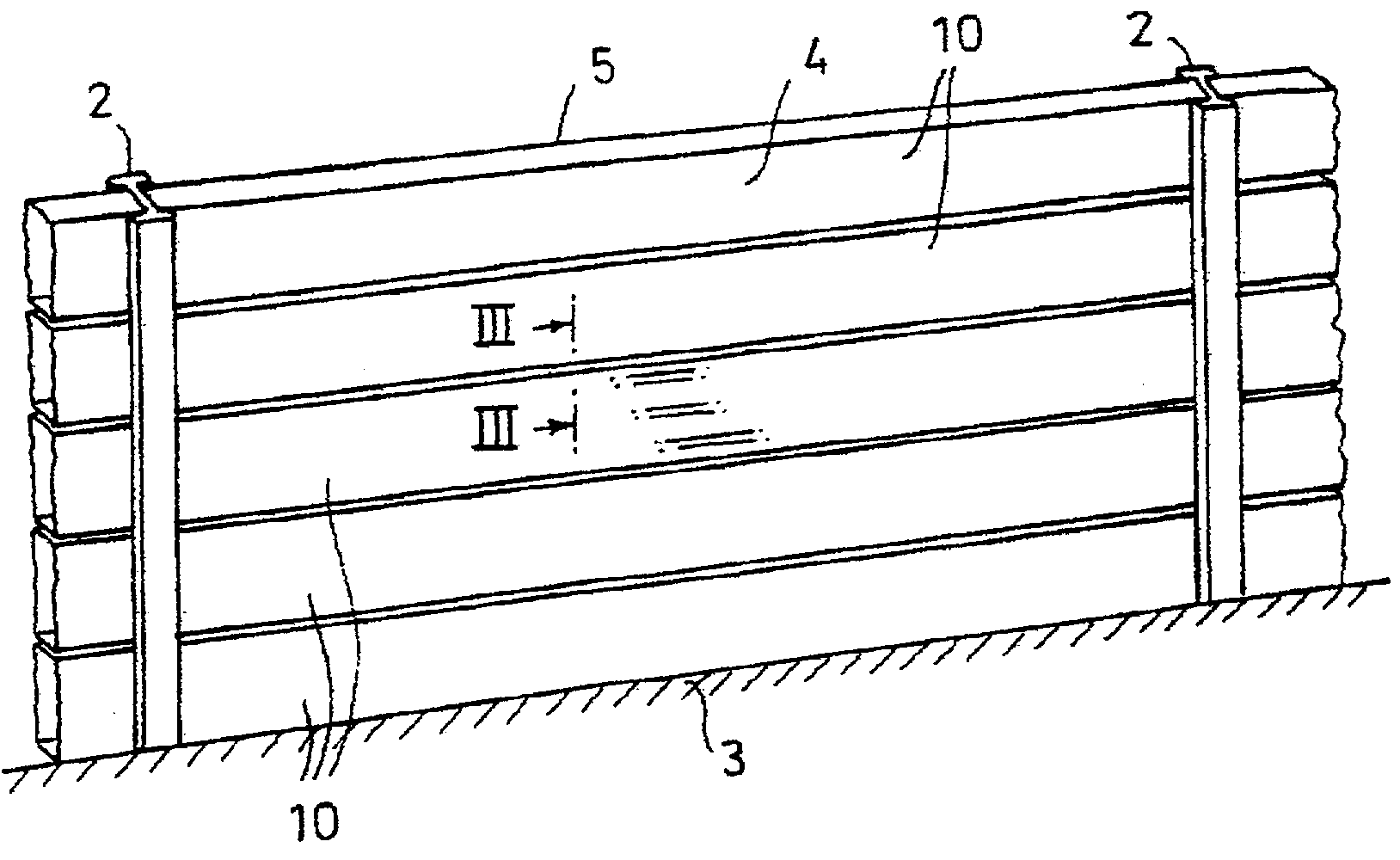
- фиг.1: в перспективе и в сильно упрощенном виде шумозащитный экран с горизонтальным расположением отдельных шумозащитных элементов;- figure 1: in the future and in a very simplified form, a noise shield with a horizontal arrangement of individual noise insulation elements;
- фиг.2: вертикальный разрез шумозащитного элемента согласно полезной модели в первом примере выполнения;- figure 2: a vertical section of a soundproofing element according to a utility model in a first embodiment;
- фиг.3: разрез по линии III-III на фиг. 1;- Fig.3: section along the line III-III in Fig. 1;
- фиг.4: вертикальный разрез шумозащитного элемента согласно полезной модели во втором примере выполнения;- figure 4: a vertical section of a noise protection element according to a utility model in a second embodiment;
- фиг.5: сильно упрощенный вид сверху на паз в боковых стенках во втором примере выполнения;- figure 5: a greatly simplified top view of the groove in the side walls in the second embodiment;
- фиг.6: подробный вид в разрезе по линии VI-VI на фиг. 5;- FIG. 6: detailed sectional view taken along line VI-VI of FIG. 5;
- фиг.7: подробность VII на фиг. 6;- FIG. 7: detail VII in FIG. 6;
- фиг.8: подробный вид в разрезе по линии VIII-VIII на фиг.5;- Fig. 8: is a detailed sectional view taken along line VIII-VIII in Fig. 5;
- фиг.9: опирающийся на бетонный цоколь самый нижний шумозащитный элемент во втором примере выполнения;- Fig.9: based on the concrete base of the lowest soundproofing element in the second embodiment;
- фиг.10: горизонтальный разрез двух закрепленных на стойке шумозащитных элементов во втором примере выполнения.- figure 10: a horizontal section of two mounted on a rack of noise insulation elements in the second embodiment.
На фиг.1 изображен обозначенный, в целом, поз. 1 шумозащитный экран, образованный несколькими шумозащитными элементами 10, расположенными горизонтально друг над другом. Шумозащитные элементы 10 закреплены своими торцевыми концами в стойках 2 двутаврового профиля, заанкеренных в бетонном фундаменте 3. Шумозащитные элементы 10 состоят из удлиненных, самонесущих и собранных в пустотелый коробчатый профиль непрерывно прессованных профильных листов, причем одна из сторон большой площади каждого шумозащитного элемента 10 образует переднюю стенку 4 и обращена к источнику шума, например, рельсам высокоскоростного участка пути, тогда как обращенная от источника шума сторона образует заднюю стенку 5. Как передняя 4, так и задняя 5 стенки могут быть снабжены перфорированным узором для преломления звука, как это, в принципе, известно из уровня техники.Figure 1 shows the designated, in General, pos. 1, a noise shield formed by several noise insulation elements 10 arranged horizontally one above the other. Noise protection elements 10 are fixed with their end ends in racks 2 of an I-beam profile, anchored in a concrete foundation 3. Noise protection elements 10 consist of elongated, self-supporting and continuously pressed profile sheets assembled into a hollow box-shaped profile, one of the sides of a large area of each noise protection element 10 forming a front wall 4 and facing the noise source, for example, the rails of the high-speed section of the track, while the side facing away from the noise source forms the rear wall 5. Like the front 4 , and the rear 5 walls can be equipped with a perforated pattern for refracting sound, as this, in principle, is known from the prior art.
Строение шумозащитного элемента 10 в первом примере выполнения поясняется со ссылкой на фиг.2 и 3. Каждый шумозащитный элемент 10 состоит из двух идентичных, изготовленных в виде непрерывно прессованных профилей из подходящего алюминиевого сплава, получашеобразных профильных листов 11,11', каждый из которых имеет стеновую поверхность 12 большой площади, образующую в соответствии с ориентацией шумозащитного элемента 10 переднюю 4 или заднюю 5 стенку шумозащитного элемента 10. На фиг. 2 и 3 левая стеновая поверхность 12 обозначена как передняя стенка 4, а правая стеновая поверхность 12 - как задняя стенка 5. Видно, однако, что задняя и передняя стенки могут быть образованы соответственно другой стеновой поверхностью. Стеновые поверхности 12 обоих профильных листов 11,11' вместе с обозначенной в целом поз. 6 нижней и обозначенной в целом поз. 7 верхней боковыми стенками образуют полость 8, в которой расположено звукоизолирующее тело 9, состоящее в примерах выполнения по фиг. 2 и 3 из изолирующей волокнистой плиты. Обе получаши 11,11' профильных листов образуют в изображенном состоянии монтажа, следовательно, пустотелый коробчатый профиль с полостью 8. Звукоизолирующее тело 9, передняя 4 и задняя 5 стенки расположены симметрично относительно средней плоскости М шумозащитного элемента 10. Образующие переднюю 4 и заднюю 5 стенки стеновые поверхности 12 обоих профильных листов 11,11' на боковых краях переходят как одно целое в обозначенные в целом поз.13А,13В, уже выполненные при первоначальном формообразовании профильных листов участки, причем оба участка 13А,13В проходят до средней плоскости М. Каждый получашеобразный профильный лист 11,11' снабжен на одном боковом краю участком 13А, а на другом боковом краю - участком 13В, соединенными между собой на высоте средней плоскости М с геометрическим замыканием посредством обозначенного в целом поз. 15 профильного соединения. Верхняя 6 и нижняя 7 боковые стенки образованы соответственно лишь наполовину участком 13А и наполовину - участком 13В. Профильное соединение включает в себя при этом, с одной стороны, профильный участок 16 на свободном конце участка 13А в качестве первого соединительного элемента, который входит с геометрическим замыканием в образующий второй соединительный элемент паз 17 в виде полости, окруженной стенкой 18, выполненной на свободном конце участка 13В. Блочный профильный участок 16 выполнен при этом за одно целое с продолжением промежуточной полки 19А участка 13А и окружающей полость паза 17 стенкой 18 на свободном конце промежуточной полки 19В участка 13В. Как хорошо видно, в частности, на фиг.3, профильный участок 16 проходит, по существу, симметрично обеим сторонам средней плоскости М, а паз 17 в виде полости выполнен также симметричным относительно зоны средней плоскости М. Это минимизирует действующие на место соединения динамические усилия, поскольку средняя плоскость М в отношении динамических нагрузок совпадает с нейтральным волокном или нейтральной плоскостью горизонтально установленного шумозащитного элемента 10. Профильное соединение 15 между профильными листами 11,11' или участками 13А,13В достигается за счет ввода профильного участка 16 в паз 17 в виде полости и продольного смещения обоих профильных листов 11,11' по отношению друг к другу, которые для этого устанавливают с разворотом на 180° по отношению друг к другу, прежде чем вдвинуть их друг в друга.The structure of the soundproofing element 10 in the first exemplary embodiment is explained with reference to FIGS. 2 and 3. Each soundproofing element 10 consists of two identical, made in the form of continuously extruded profiles from a suitable aluminum alloy, half-shaped profile sheets 11,11 ', each of which has a large surface area 12, which, in accordance with the orientation of the noise reduction element 10, forms the front 4 or rear 5 wall of the noise reduction element 10. In FIG. 2 and 3, the left wall surface 12 is designated as the front wall 4, and the right wall surface 12 is designated as the rear wall 5. However, it is seen that the rear and front walls can be formed respectively by another wall surface. Wall surfaces 12 of both profile sheets 11.11 'together with the generally designated pos. 6 bottom and indicated in general pos. 7, the upper side walls form a cavity 8 in which a sound-insulating body 9 is located, consisting in the exemplary embodiments of FIG. 2 and 3 of an insulating fiber board. Both halves of 11.11 'profile sheets form in the illustrated installation state, therefore, a hollow box-shaped profile with a cavity 8. The sound-insulating body 9, the front 4 and rear 5 walls are located symmetrically with respect to the middle plane M of the soundproofing element 10. Forming the front 4 and rear 5 walls the wall surfaces 12 of both profiled sheets 11.11 'on the lateral edges go integrally into the sections 13A, 13B indicated on the whole, already completed during the initial shaping of the profile sheets, both sections 13A, 13B extend to the middle plane M. Each half-shaped profile sheet 11.11 'is provided on one side edge with a portion 13A, and on the other side edge with a portion 13B interconnected at a height of the middle plane M with a geometric closure by means of the generally designated position. 15 profile connections. The upper 6 and lower 7 side walls are respectively formed only half section 13A and half section 13B. In this case, the profile connection includes, on the one hand, the profile section 16 at the free end of the section 13A as the first connecting element, which is inserted with a geometric closure into the groove 17 forming the second connecting element in the form of a cavity surrounded by a wall 18 made on the free end plot 13B. The block profile section 16 is made integral with the continuation of the intermediate flange 19A of the section 13A and the wall 18 surrounding the cavity of the groove 17 at the free end of the intermediate shelf 19B of the section 13B. As can be clearly seen, in particular in FIG. 3, the profile section 16 extends essentially symmetrically to both sides of the middle plane M, and the groove 17 in the form of a cavity is also symmetrical with respect to the zone of the middle plane M. This minimizes the dynamic forces acting on the joint , since the middle plane M in relation to dynamic loads coincides with the neutral fiber or the neutral plane of the horizontally mounted noise insulation element 10. Profile connection 15 between the profile sheets 11.11 'or sections 1 3A, 13B is achieved by inserting the profile portion 16 into the groove 17 in the form of a cavity and the longitudinal displacement of both profile sheets 11,11 'with respect to each other, which for this is set with a 180 ° turn with respect to each other before sliding them into each other.
Профильный участок 16 через полочное продолжение 20 соединен за одно целое с промежуточной полкой 19А участка 13А, а отформованная за одно целое с промежуточной полкой 19В стенка 18 полости паза 17 имеет в осевом продолжении промежуточной полки 19В отверстие 21, через которое проходит полочное продолжение 20. Паз 17 в виде полости проходит относительно отверстия 21 вверх и вниз, так что стенка 18 участка 13В образует с обеими ограничительными полками 22,23 отверстия 21 на профильном листе 11 поднутрение для профильного участка 16 на участке 13А другого профильного листа 11'. Профильный участок 16 и паз 17 в виде полости имеют в изображенном примере выполнения прямоугольное сечение.The profile section 16 is connected in one piece with the intermediate shelf 19A of the section 13A through the shelf extension 20, and the wall 18 of the groove cavity 17 formed integrally with the intermediate shelf 19B has an opening 21 in the axial extension of the intermediate shelf 19B through which the shelf extension 20 passes. 17 in the form of a cavity extends upward and downward with respect to the opening 21, so that the wall 18 of section 13B forms, with both restrictive shelves 22,23, the holes 21 on the profile sheet 11 undercut for the profile section 16 on the section 13A of another profile sheet 11 '. The profile section 16 and the groove 17 in the form of a cavity have a rectangular section in the illustrated embodiment.
Промежуточные полки 19А,19В обоих профильных листов 11,11' относительно опорных полок 14А,14В, проходящих под прямым углом к стеновым поверхностям 12 и примыкающих непосредственно к боковым краям передней 5 и задней 5 стенок, смещены назад в полость 8 посредством промежуточных полок 24А,24В, так что верхние 6 и нижние 7 боковые стенки двух расположенных друг над другом шумозащитных элементов 10 прилегают друг к другу только в зоне опорных полок 14А,14В и в зоне наружной полки 25 стенки 18 полости паза 17. Обе промежуточные полки 19А,19В, непосредственно примыкая к смещенным полкам 24А,24В, снабжены Т-образным приемным пазом 27, который ограничен двумя выполненными за одно целое с прессованными профильными листами 11 L-образными полками 28,29. Приемный паз 27 и L-образные полки 28,29 выполнены при этом соответственно на внутренней стороне профиля, так что они находятся у шумозащитных элементов 10 в полости 8. В-образные приемные пазы 27 вставлены опорные планки 40 для поддержания с боков звукоизолирующего тела 9. Выполненная с профильным участком 16 для профильного соединения 15 промежуточная полка 19А снабжена далее двумя отформованными за одно целое с ней и с наружной стороны угловыми ребрами 30,31, ограничивающими Т-образную приемную камеру 32, в которую может быть вставлена разжимная уплотнительная планка 45, выполняющая дополнительно звукоизолирующую функцию между боковыми стенками 6,7 шумозащитных элементов 10. Угловое ребро 31 отформовано на промежуточной полке 19А таким образом, что оно в состоянии монтажа одним из своих участков параллельно упирается в ребристый отрезок 23 стенки 18 полости паза 17, чтобы в продольном направлении шумозащитных элементов фиксировать профильное соединение 15 также за счет контактного трения. На фиг. 2 и 3 не показано, что профильное соединение 15 у шумозащитного элемента в первом примере выполнения дополнительно к геометрическому замыканию может быть еще фиксировано одним или, в частности, несколькими фиксирующими средствами, которые расположены также соосно с нейтральным волокном шумозащитного элемента, следовательно, здесь со средней плоскостью М. Фиксирующие средства могут состоять, в частности, из вставного или резьбового соединения, которое проходит, например, через наружную полку стенки 18 полости паза 17 и ввинчено или вставлено в профильный участок 16. С помощью фиксирующих средств можно тогда закрепить также торцевую крышку (не показана), которая закрывает также с торца полость образованного профильными листами 11,11' пустотелого коробчатого профиля.The intermediate shelves 19A, 19B of both profile sheets 11,11 'relative to the supporting shelves 14A, 14B, passing at right angles to the wall surfaces 12 and adjacent directly to the side edges of the front 5 and rear 5 walls, are shifted back into the cavity 8 by means of intermediate shelves 24A, 24B, so that the upper 6 and lower 7 side walls of the two noise-canceling elements 10 located one above the other are adjacent to each other only in the area of the support shelves 14A, 14B and in the area of the outer shelf 25 of the wall 18 of the groove cavity 17. Both intermediate shelves 19A, 19B, directly adjacent I to the displaced shelves 24A, 24B, are equipped with a T-shaped receiving groove 27, which is limited to two 11 L-shaped shelves 28,29 made in one piece with extruded profile sheets. The receiving groove 27 and the L-shaped shelves 28,29 are made, respectively, on the inner side of the profile, so that they are located near the noise-attenuating elements 10 in the cavity 8. B-shaped receiving grooves 27 are fitted with support bars 40 for supporting the soundproof body 9 from the sides. The intermediate flange 19A made with the profile section 16 for the profile connection 15 is further provided with two angular ribs 30.31 molded integrally with it and from the outside, bounding the T-shaped receiving chamber 32 into which the expandable seal can be inserted a relative bar 45, which additionally performs a soundproofing function between the side walls of the 6.7 soundproofing elements 10. The corner rib 31 is molded on the intermediate flange 19A so that it is mounted in one of its sections in parallel with the ribbed segment 23 of the wall 18 of the groove cavity 17, so that in the longitudinal direction of the noise protection elements to fix the profile connection 15 also due to contact friction. In FIG. 2 and 3, it is not shown that the profile connection 15 of the noise protection element in the first exemplary embodiment, in addition to the geometric closure, can also be fixed by one or, in particular, several locking means, which are also aligned with the neutral fiber of the noise protection element, therefore, here with the middle plane M. The locking means may consist, in particular, of an insert or threaded connection, which passes, for example, through the outer shelf of the wall 18 of the cavity of the groove 17 and screwed or inserted a profile section 16. By means of fixing means can then fix also endcap (not shown) which also closes an end cavity formed by profiled sheets 11,11 'of the hollow box profile.
Стеновые поверхности 12 обоих профильных листов 11,11' каждого шумозащитного элемента 10, как показано на фиг.2, снабжены несколькими, первоначально формоизмененными при прессовании профильных листов 11 стабилизирующими ребрами 35, которые проходят по всей длине шумозащитных элементов 10 с постоянным сечением и имеют, по существу, Y-образный профиль. В изображенном примере выполнения оба профильных листа 11,11' снабжены двумя, расположенными со смещением на 1/3 общей высоты стабилизирующими ребрами 35. Понятно, что в зависимости от ожидаемых динамических нагрузок могут быть предусмотрены дополнительные стабилизирующие ребра 35, при необходимости также разной геометрической формы для продольных желобков и ребристых продолжений. Шумозащитные элементы имеют с обеих сторон профильного соединения 15 или сбоку и снизу внутренней полки 34 по одному каналу 38,39, причем канал 38 проходит между полкой 28 и вертикальным ребром стенки 18, а канал 39 выполнен между ограничительной полкой 22 и полкой 28, тогда как звукоизолирующее тело опирается на опорные планки 40 и внутреннюю полку 34.The wall surfaces 12 of both profile sheets 11.11 'of each soundproofing element 10, as shown in FIG. 2, are provided with several stabilizing ribs 35 that are initially shaped when pressing the profile sheets 11, which extend over the entire length of the soundproofing elements 10 with a constant cross section and have, essentially a Y-shaped profile. In the depicted exemplary embodiment, both profile sheets 11.11 'are provided with two stabilizing ribs 35 arranged with an offset of 1/3 of the total height. It is understood that, depending on the expected dynamic loads, additional stabilizing ribs 35, if necessary also of different geometric shapes, can be provided for longitudinal grooves and ribbed extensions. Noise protection elements have one channel 38.39 on either side of the profile connection 15, either on the side and bottom of the inner shelf 34, the channel 38 passing between the shelf 28 and the vertical edge of the wall 18, and the channel 39 is made between the restrictive shelf 22 and the shelf 28, while sound insulating body rests on the support strips 40 and the inner shelf 34.
На фиг.4-10 изображен второй пример выполнения шумозащитного элемента 100. Также шумозащитный элемент 100 состоит из двух идентичных, изготовленных в виде непрерывно прессованных профилей из подходящего алюминиевого сплава, получашеобразных профильных листов 111,111', имеющих соответственно стеновую поверхность 112 большой площади, которые в соответствии с ориентацией шумозащитного элемента 100, как показано на фиг. 4, образуют переднюю 104 и заднюю 105 стенки. Профильный лист 111, обращенный к передней стенке, т.е. к источнику шума, таким как рельсы, может быть выполнен перфорированным, причем доля перфорированной поверхности по отношению ко всей площади передней стенки 104 может составлять примерно 27%. Задняя стенка 105 шумозащитных элементов 100, предпочтительно, не перфорирована. Стеновые поверхности 112 обоих профильных листов 111,111' вместе с верхней 106 и нижней 107 боковыми стенками образуют полость 8, в которой расположено подходящее звукоизолирующее тело 109, которое, как в первом примере выполнения, может состоять из единственной изолирующей волокнистой плиты. На фиг. 4 видно, что обе получаши 111,111' профильных листов соединены между собой в шумозащитный элемент 100 посредством соединительного профильного тела 160, поддерживающего звукоизолирующее тело 109 и расположенного в полости 108 рядом с верхней 106 и нижней 107 стенками. Соединение обоих профильных листов 111,111' с геометрическим замыканием с соединительным профильным телом 160, осуществленное исключительно в зоне средней плоскости М шумозащитного элемента 100, обозначено на фиг. 6-8 поз. 115 и более подробно поясняется со ссылкой на эти фигуры.Figures 4-10 show a second exemplary embodiment of the soundproofing element 100. Also, the soundproofing element 100 consists of two identical profiles made in the form of continuously extruded profiles of a suitable aluminum alloy, half-shaped profile sheets 111,111 'having, respectively, a large surface area 112, which in accordance with the orientation of the noise protection element 100, as shown in FIG. 4 form a front wall 104 and a rear wall 105. Profile sheet 111 facing the front wall, i.e. to a noise source, such as rails, can be perforated, and the proportion of the perforated surface relative to the entire area of the front wall 104 may be approximately 27%. The rear wall 105 of the noise protection elements 100 is preferably not perforated. The wall surfaces 112 of both profiled sheets 111,111 ′ together with the upper 106 and lower 107 side walls form a cavity 8 in which a suitable sound insulating body 109 is located, which, as in the first embodiment, may consist of a single insulating fibrous plate. In FIG. 4 it can be seen that both half-plates 111,111 ′ of the profile sheets are interconnected into a noise-protecting element 100 by means of a connecting profile body 160 supporting the sound-insulating body 109 and located in the cavity 108 near the upper 106 and lower 107 walls. The connection of both profile sheets 111,111 'with a geometric closure with the connecting profile body 160, carried out exclusively in the area of the middle plane M of the noise protection element 100, is indicated in FIG. 6-8 poses 115 and is explained in more detail with reference to these figures.
На фиг.6-8 изображен вертикальный разрез шумозащитных элементов 100 в зоне верхней боковой стенки 106 и соединительного профильного тела 160. Для соединения с геометрическим замыканием обоих профильных листов 111,111' соединительное профильное тело 160 снабжено пазом 162 на своей передней стороне 161, обращенной к боковой стенке 106 и примыкающей к ее внутренней стороне. На этом пазу 162 обе профильные получаши 111,111' фиксируют с геометрическим замыканием и соединяют между собой также с геометрическим замыканием. Оба профильных листа 111,111' переходят на своих обеих боковых стенках 106,107 за одно целое в участки 113А,113В, причем каждый из участков 113А,113В имеет прежде всего примыкающую к вертикально проходящим передней и задней стенкам, ориентированную под прямым углом к ним опорную полку 114А,114В, которая через отогнутую внутрь смещенную полку 124А,124В переходит в проходящую также перпендикулярно боковым стенкам и параллельно опорным полкам 114А,114В промежуточную полку 119А,119В, на концах которой выполнены отогнутые внутрь кромки 116 или кромочные ребра. Обе кромки 116 на обеих промежуточных полках 119А,119В входят в паз 162 (фиг. 7) и упираются в боковые стороны 162' паза 162, так что за счет этого оба профильных листа 111,111' соединены между собой с геометрическим замыканием в зоне средней плоскости М. Это соединение с геометрическим замыканием обоих профильных листов 111,111' с пазом 162 в соединительном профильном теле 160 фиксировано резьбовыми соединениями 170,180 в качестве дополнительной фиксации, что поясняется ниже.FIGS. 6-8 show a vertical section of the noise insulation elements 100 in the region of the upper side wall 106 and the connecting profile body 160. For connecting with the geometric closure of both profile sheets 111,111 ′, the connecting profile body 160 is provided with a groove 162 on its front side 161 facing the side wall 106 and adjacent to its inner side. In this groove 162, both profile half-holes 111,111 'are fixed with a geometric closure and are interconnected also with a geometric closure. Both profile sheets 111,111 'pass on their both side walls 106,107 integrally into sections 113A, 113B, and each of sections 113A, 113B has, first of all, an abutment shelf 114A adjacent to the vertically extending front and rear walls, oriented at right angles to them. 114B, which, through an inwardly deflected flange 124A, 124B, passes into an intermediate flange 119A, 119B also perpendicular to the side walls and parallel to the support flanges 114A, 114B, at the ends of which there are inwardly curved edges 116 or edge ribs. Both edges 116 on both intermediate flanges 119A, 119B enter the groove 162 (Fig. 7) and abut against the sides 162 'of the groove 162, so that both profile sheets 111,111' are connected to each other with a geometric closure in the middle plane M This connection with a geometric closure of both profile sheets 111.111 'with a groove 162 in the connecting profile body 160 is fixed by threaded connections 170.180 as an additional fixation, which is explained below.
Соединительные профильные тела 160 состоят из экструдированных прессованных профильных тел из алюминия и имеют сравнительно широкое, выполненное из сплошного материала среднее ребро 164, которое расположено в средней плоскости М шумозащитного элемента 100 и образует основание паза 162. Соединительное профильное тело 160 проходит с обеих сторон среднего ребра 164 с пустотелым участком 165, причем нижняя стенка 166 каждого пустотелого участка 165 имеет отстоящие под прямым углом опорные ребра 167 для бокового поддержания изолирующей плиты 109, боковые стенки 168 полости прилегают изнутри к профильным листам 111,111', а примыкающая к боковой стенке 106 передняя стенка 161 имеет отогнутые в соответствии с формой боковой стенки 106 участки со смещенной полкой 169 полости. Соединительное профильное тело 160 прилегает, следовательно, в зоне верхних и нижних концов шумозащитных элементов 100 с геометрическим замыканием к профильным листам 111,111', за счет чего достигается дополнительная жесткость шумозащитного элемента 100. Сравнительно широкое, состоящее из сплошного материала среднее ребро 164 соединительного профильного тела 160 рассчитано с возможностью ввинчивания фиксирующих винтов 171,181 в среднее ребро 164 и их анкеровки там. Фиксирующими винтами 171,181, имеющими под головкой тарелку 172,182 или зажимное кольцо, закрепляют соответственно планку 190, которая в состоянии монтажа находится внутри образованного смещенными 124А,124В и промежуточными 119А,119В полками углубления в обеих боковых стенках 106,107. Заднюю поверхность планок 190 за счет затягивания фиксирующих винтов 171,181 притягивают к соединительному телу 160 и стягивают с ним, в результате чего промежуточные полки 119А,119В обоих профильных листов 111,111' зажимаются между планкой 190 и соединительным профильным телом 160. Эта мера способствует вхождению кромок 116 с геометрическим замыканием в паз 162 соединительного профильного тела 160 дополнительно за счет зажима соответствующих участков 113А,113В профильных листов 111,111'. Оба участка 113А,113В, сообща образующих верхнюю 106 и нижнюю 107 боковые стенки каждого шумозащитного элемента 100, фиксированы, следовательно, как за счет геометрического замыкания, так и за счет зажима, причем как зажим, так и геометрическое замыкание сконцентрированы, в частности, в зоне средней плоскости М и, тем самым, в зоне наименьших динамических нагрузок.The connecting profile bodies 160 are composed of extruded extruded aluminum profile bodies and have a relatively wide, continuous solid rib 164, which is located in the mid-plane M of the noise attenuation element 100 and forms the base of the groove 162. The connecting profile body 160 extends on both sides of the middle rib 164 with a hollow portion 165, the lower wall 166 of each hollow portion 165 having right-angled support ribs 167 for laterally supporting the insulating plate 109, lateral Tenkai 168 inside the cavity adjacent to the core sheets 111,111 ', and adjacent to the side wall 106 front wall 161 is bent according to the shape of the side wall portions 106 with shelf 169 offset cavity. The connecting profile body 160 is therefore adjacent in the region of the upper and lower ends of the noise protection elements 100 with a geometrical closure to the profile sheets 111,111 ', whereby an additional stiffness of the noise protection element 100 is achieved. A relatively wide middle rib 164 of the connecting profile body 160 consisting of solid material Designed to screw the fixing screws 171.181 into the middle rib 164 and anchor them there. Locking screws 171,181, having a plate 172,182 under the head or a clamping ring, respectively fasten the strip 190, which is in a mounted state inside the recesses formed in the displaced 124A, 124B and intermediate 119A, 119B in both side walls 106,107. By tightening the fixing screws 171.181, the rear surface of the strips 190 is pulled to and pulled together with the connecting body 160, as a result of which the intermediate flanges 119A, 119B of both profile sheets 111,111 'are clamped between the bracket 190 and the connecting profile body 160. This measure allows the edges 116 to enter geometrical closure in the groove 162 of the connecting profile body 160 additionally by clamping the corresponding sections 113A, 113B of the profile sheets 111,111 '. Both sections 113A, 113B, together forming the upper 106 and lower 107 side walls of each soundproofing element 100, are fixed, therefore, both due to a geometric closure and due to a clamp, both the clamp and the geometric closure are concentrated, in particular, in zone of the middle plane M and, thus, in the zone of least dynamic loads.
На фиг.8 изображен вариант выполнения фиксирующего средства 170, у которого зажим достигается исключительно посредством зажимных усилий между планкой 190 и соединительным профильным телом 160. Зажимной винт 181 лежит своей зажимной тарелкой в пазообразном углублении планки 190, проходит через паз 162 соединительного профильного тела 160 и своим резьбовым отрезком ввинчен в среднее ребро 164.Fig. 8 shows an embodiment of a fixing means 170 in which clamping is achieved exclusively by clamping forces between the strip 190 and the connecting profile body 160. The clamping screw 181 lies with its clamping plate in the grooved recess of the strip 190, passes through the groove 162 of the connecting profile body 160 and screwed into the middle rib 164 with its threaded section.
На фиг.6 и 7 изображено особенно предпочтительное выполнение для дополнительных зажима и фиксации обоих профильных листов 111,111' в профильном соединении 115 с соединительным профильным телом 160. В качестве дополнительной защитной меры изображенное на фиг. 6 и 7 фиксирующее средство 170 содержит зажимную втулку 175 из высококачественной стали, расположенную в пазу 162. На фиг. 5 видно, что паз 162 в той зоне, где располагают фиксирующие средства 170 с зажимными втулками 175, имеет расширение 176. Расширение 176 паза 162 может быть реализовано, в частности, раззенковкой или раззенкованным отверстием, причем эту раззенковку выполняют в соединительных профильных телах, прежде чем они будут помещены внутрь шумозащитных элементов 100 для соединения с геометрическим замыканием обоих профильных листов 111,111'. За счет расположения зажимных втулок 175 в снабженном расширением 176 пазу и затягивания входящего в среднее ребро 164 крепежного винта 171 обе лишь обозначенные на фиг. 5 кромки 116 на концах обоих участков 113А,113В также расширяются и, тем самым, втягиваются в расширение 176. Это дополнительное выступающее профилирование кромок 116 фиксирует профильные листы 111,111' с геометрическим замыканием в отношении всех усилий в продольном направлении шумозащитных элементов 100, причем также это соединение с геометрическим замыканием поддержано и фиксировано за счет зажима посредством зажимной втулки 175, а также зажимных усилий, действующих между планкой 190 и передней стенкой 161 соединительного профильного тела. Дополнительная фиксация за счет частичного расширения и сгибания кромок 116 обеспечивает дополнительную стойкость шумозащитного элемента 100, согласно изобретению, к динамическим нагрузкам и колебаниям, которые могут возникать при прохождении мимо высокоскоростного поезда. У шумозащитного элемента 100, согласно изобретению, применяться могут при этом исключительно фиксирующие средства 170 с зажимными втулками 175.Figures 6 and 7 show a particularly preferred embodiment for additional clamping and fixing of both profile sheets 111,111 'in the profile connection 115 with the connecting profile body 160. As an additional protective measure, shown in FIG. 6 and 7, the locking means 170 comprises a stainless steel clamping sleeve 175 located in the groove 162. In FIG. 5 it can be seen that the groove 162 in the area where the fixing means 170 with the clamping sleeves 175 are located has an extension 176. The extension 176 of the groove 162 can be implemented, in particular, by countersinking or countersink hole, and this countersinking is performed in connecting profile bodies, before than they will be placed inside the noise protection elements 100 for connecting with geometrical closure of both profile sheets 111,111 '. Due to the arrangement of the clamping sleeves 175 in the groove provided with the extension 176 and the tightening of the fastening screw 171 included in the middle rib 164, both are only indicated in FIG. 5, the edges 116 at the ends of both sections 113A, 113B also expand and are thus pulled into the extension 176. This additional protruding profiling of the edges 116 fixes the profile sheets 111,111 'with a geometric closure in relation to all the forces in the longitudinal direction of the noise protection elements 100, and this also the geometric locking connection is supported and fixed by clamping by means of a clamping sleeve 175, as well as clamping forces acting between the strip 190 and the front wall 161 of the connecting profile body. Additional fixation due to partial expansion and bending of the edges 116 provides additional resistance of the noise protection element 100, according to the invention, to dynamic loads and vibrations that may occur when passing by a high-speed train. In the case of the soundproofing element 100 according to the invention, exclusively fixing means 170 with clamping sleeves 175 can be used.
Здесь следует снова сослаться на фиг.4, 9, 10. На этих фигурах хорошо видно, что в планки 190, стянутые фиксирующими винтами 181 с соединительным профильным телом 160, с обеих сторон принимающего головку винта 181 пазообразного углубления выполнены гнезда 195 для О-образных уплотнительных средств 145 или уплотнительных планок. Каждое гнездо 195 имеет направленный наружу, полукруглый в сечении желобок 196, к которому может прилегать О-образный отрезок уплотнительного средства 145, а также открытый ко дну или вершине два желобка 196 канал 197, в котором уплотнительное средство 145 может быть заанкерено с помощью примыкающего за одно целое к О-образному отрезку Т-образного отрезка и т.п. В состоянии монтажа двух расположенных друг над другом шумозащитных элементов 100, как показано на фиг. 4, уплотнительное средство прилегает О-образным отрезком соответственно наполовину к желобку 196 противоположных друг другу планок 190, в результате чего достигается эффективная герметизация между боковыми стенками 106,107 шумозащитных элементов. Одинаковые, заанкеренные в гнездах 195 планок 190 уплотнительные средства 145 могут быть использованы для поддержания самого нижнего шумозащитного элемента 100 герметизированным на бетонном цоколе 103.Here, reference should again be made to FIGS. 4, 9, 10. In these figures it is clearly seen that the slats 195 for O-shaped holes are made on both sides of the slats 190, tightened by the fixing screws 181 with the connecting profile body 160, on both sides sealing means 145 or sealing strips. Each socket 195 has an outwardly semicircular groove 196, to which an O-shaped segment of the sealing means 145 can adjoin, as well as a channel 197 open to the bottom or top of the two grooves 196, in which the sealing means 145 can be anchored by means of an adjacent one to the O-shaped segment of the T-shaped segment, etc. In the installation state of two mutually arranged noise suppression elements 100, as shown in FIG. 4, the sealing means abuts with an O-shaped segment, respectively, halfway to the groove 196 of the strips 190 opposite to each other, as a result of which effective sealing between the side walls 106,107 of the noise protection elements is achieved. The same sealing means 145 anchored in the slots 195 of the slats 190 can be used to keep the lowest soundproofing element 100 sealed on the concrete base 103.
На фиг.4 и 9 показано также, что соединительные профильные тела 160 в зоне среднего ребра 164, отделяющего друг от друга обе профильные камеры 165 и служащие для фиксации фиксирующих средств 170,180, снабжены вблизи или с примыканием к нижней стороне 166 профильным отверстием 185 в форме замочной скважины. Это профильное отверстие 185 служит для закрепления простым образом на обеих вертикально проходящих торцевых сторонах каждого шумозащитного элемента 100 торцевой крышки 150, как это показано на фиг. 10. Схематично изображенный на фиг. 10 крепежный винт 151 для закрепления торцевой крышки 150 проходит через нее и входит затем в отверстие 185 в форме замочной скважины в среднем ребре 164. Торцевая крышка 150 снабжена крюкообразными выступами 152, которые позиционируют и поддерживают изолирующую плиту 109 также с торца. Далее торцевые крышки 150 имеют прилегающие к наружной стороне профильных листов или передней 104 и задней 105 стенок загибы 153, снабженные дополнительными гнездами для подходящих уплотнительных средств 155, которые в состоянии монтажа шумозащитного экрана расположены между полками 2' двутавровых стоек 2 и передними 104 и задними 105 стенками в зоне торцевых концов шумозащитных элементов 100 для предотвращения возникновения колебаний. Все уплотнительные средства могут состоять из СКЭПТ-уплотнений или других подходящих уплотнений. Далее профильные листы 111,111' могут быть снабжены подходящими продольными профилированиями, такими как изображенные на фиг. 4 продольные профилирования 135, для достижения дополнительной жесткости.FIGS. 4 and 9 also show that the connecting profile bodies 160 in the area of the middle rib 164 separating from each other both profile chambers 165 and serving to fix the fixing means 170,180, are provided near or adjacent to the lower side 166 with a profile hole 185 in the form keyhole. This profile hole 185 serves to simply fix on both vertically extending end faces of each soundproofing element 100 of the end cover 150, as shown in FIG. 10. Schematically depicted in FIG. 10, a fixing screw 151 for securing the end cap 150 passes through it and then enters the keyhole-shaped hole 185 in the middle rib 164. The end cap 150 is provided with hook-shaped protrusions 152 that position and support the insulating plate 109 also from the end. Further, the end caps 150 have bends 153 adjacent to the outside of the profile sheets or the front 104 and rear 105 walls, provided with additional sockets for suitable sealing means 155, which are located between the shelves 2 'of the I-pillars 2 and the front 104 and rear 105 walls in the area of the end ends of the noise insulation elements 100 to prevent oscillations. All sealing means may consist of SKEPT seals or other suitable seals. Further, the profiling sheets 111,111 'may be provided with suitable longitudinal profiling, such as those shown in FIG. 4 longitudinal profiling 135, to achieve additional rigidity.
Для специалиста из предшествующего описания следуют многочисленные возможности применения, подпадающие под объем охраны формулы полезной модели. Нейтральное волокно необязательно должно совпадать со средней плоскостью. Для профильного соединения в первом примере выполнения оба участка могут иметь также соединительные элементы других сечений, например, в форме ласточкина хвоста и т.п. Звукоизолирующее тело может состоять из любых подходящих материалов, причем в том же пустотелом коробчатом профиле за счет использования других опорных планок могут быть помещены также звукоизолирующие тела других толщин. В полости шумозащитных элементов могут быть расположены также звукоизолирующие тела, состоящие из двух полупоглощающих изолирующих волокнистых плит, которые находятся с обеих сторон расположенной по центру в средней плоскости шумозащитного элемента древесно-волокнистой цементной плиты и т.п. Выполненные, согласно изобретению, шумозащитные элементы и шумозащитные экраны могут использоваться, в частности, на отрезках железнодорожных путей для высокоскоростных поездов, на взлетно-посадочных полосах для самолетов и в других областях, где на шумозащитные элементы и экраны действуют высокие динамические сжимающие и подсасывающие нагрузки.For a specialist, from the preceding description, numerous application possibilities follow that fall within the scope of protection of the utility model formula. The neutral fiber does not have to coincide with the middle plane. For the profile connection in the first embodiment, both sections can also have connecting elements of other sections, for example, in the form of a dovetail, etc. The sound insulating body may consist of any suitable materials, and sound insulating bodies of other thicknesses can also be placed in the same hollow box-shaped profile by using other support strips. Sound-insulating bodies can also be located in the cavity of the soundproofing elements, consisting of two semi-absorbing insulating fibrous boards, which are located on both sides, centered in the middle plane of the soundproofing member of a wood-fiber cement slab, etc. The soundproofing elements and soundproofing screens made according to the invention can be used, in particular, on sections of railway tracks for high-speed trains, on runways for aircraft and in other areas where high dynamic compressive and suction loads act on the soundproofing elements and screens.
Claims (24)
Applications Claiming Priority (2)
| Application Number | Priority Date | Filing Date | Title |
|---|---|---|---|
| EP04026119.0 | 2004-11-04 | ||
| EP04026119A EP1529883B1 (en) | 2003-11-04 | 2004-11-04 | Sound-damping wall and element therefor |
Publications (1)
| Publication Number | Publication Date |
|---|---|
| RU49834U1 true RU49834U1 (en) | 2005-12-10 |
Family
ID=35869163
Family Applications (1)
| Application Number | Title | Priority Date | Filing Date |
|---|---|---|---|
| RU2005112867/22U RU49834U1 (en) | 2004-11-04 | 2005-04-27 | NOISE PROTECTIVE ELEMENT AND NOISE PROTECTIVE SCREEN |
Country Status (1)
| Country | Link |
|---|---|
| RU (1) | RU49834U1 (en) |
Cited By (3)
| Publication number | Priority date | Publication date | Assignee | Title |
|---|---|---|---|---|
| RU2514289C2 (en) * | 2008-08-08 | 2014-04-27 | Чир Амбьенте С.П.А. | Improved barrier |
| RU2514283C2 (en) * | 2008-08-08 | 2014-04-27 | Чир Амбьенте С.П.А. | Barrier |
| RU204788U1 (en) * | 2020-12-07 | 2021-06-10 | Общество с ограниченной ответственностью "Дорнадзор" | NOISE PROTECTION SCREEN |
-
2005
- 2005-04-27 RU RU2005112867/22U patent/RU49834U1/en not_active IP Right Cessation
Cited By (3)
| Publication number | Priority date | Publication date | Assignee | Title |
|---|---|---|---|---|
| RU2514289C2 (en) * | 2008-08-08 | 2014-04-27 | Чир Амбьенте С.П.А. | Improved barrier |
| RU2514283C2 (en) * | 2008-08-08 | 2014-04-27 | Чир Амбьенте С.П.А. | Barrier |
| RU204788U1 (en) * | 2020-12-07 | 2021-06-10 | Общество с ограниченной ответственностью "Дорнадзор" | NOISE PROTECTION SCREEN |
Similar Documents
| Publication | Publication Date | Title |
|---|---|---|
| RU2246596C2 (en) | Sound-proof building structure | |
| RU2002110660A (en) | Soundproof building construction | |
| KR200396762Y1 (en) | Transparency Noise Protection Panel | |
| RU49834U1 (en) | NOISE PROTECTIVE ELEMENT AND NOISE PROTECTIVE SCREEN | |
| CA2142369A1 (en) | Board wall system | |
| CA2255245C (en) | Mounting system for panels for use in facade cladding on buildings | |
| CA2095695C (en) | Multi-functional, universal member for architectural joint systems | |
| JP4883692B2 (en) | Soundproof panel mounting structure and soundproof panel mounting method | |
| RU2381341C1 (en) | Vertical guide for attachment of facing slabs of mounted ventilated frontage | |
| KR102385827B1 (en) | Load transfer prevention type soundproof walls | |
| KR102293376B1 (en) | Rail type deck rod system | |
| JP4024489B2 (en) | Engaging member engaged with base member, base member assembly, and base member assembly method | |
| CN212802115U (en) | Guide rail vibration reduction type light steel keel wall | |
| KR100352150B1 (en) | A moulding system for filling up between wall and ceiling board | |
| KR101255216B1 (en) | Soundproof block connection structure | |
| CN219298029U (en) | Noise reduction barrier for road and bridge construction | |
| KR101943012B1 (en) | Ceiling's Hanger Bracket for reducing noise between floors and Ceiling System using it | |
| KR20020036692A (en) | Fire and soundproof panel | |
| KR100378634B1 (en) | Noise absorbing wall | |
| RU204788U1 (en) | NOISE PROTECTION SCREEN | |
| KR101332622B1 (en) | Soundproofing wall | |
| KR200230651Y1 (en) | Noise absorbing wall | |
| KR102542927B1 (en) | A wooden soundproofing board device including a wooden soundproofing wall structure that can reduce howling by height difference between wooden parts | |
| KR200234619Y1 (en) | Sound barrier | |
| RU2204668C1 (en) | Prefabricated construction unit |
Legal Events
| Date | Code | Title | Description |
|---|---|---|---|
| MM1K | Utility model has become invalid (non-payment of fees) |
Effective date: 20140428 |