EP2317329A2 - Poste à courant continu destiné à trouver des modules PV défectueux dans une installation photovoltaïque - Google Patents
Poste à courant continu destiné à trouver des modules PV défectueux dans une installation photovoltaïque Download PDFInfo
- Publication number
- EP2317329A2 EP2317329A2 EP10009607A EP10009607A EP2317329A2 EP 2317329 A2 EP2317329 A2 EP 2317329A2 EP 10009607 A EP10009607 A EP 10009607A EP 10009607 A EP10009607 A EP 10009607A EP 2317329 A2 EP2317329 A2 EP 2317329A2
- Authority
- EP
- European Patent Office
- Prior art keywords
- current
- units
- unit
- measurement
- measured
- Prior art date
- Legal status (The legal status is an assumption and is not a legal conclusion. Google has not performed a legal analysis and makes no representation as to the accuracy of the status listed.)
- Granted
Links
- 230000002950 deficient Effects 0.000 title description 20
- 238000005259 measurement Methods 0.000 claims abstract description 108
- 238000000034 method Methods 0.000 claims abstract description 37
- 238000011156 evaluation Methods 0.000 claims description 12
- 238000001514 detection method Methods 0.000 claims description 6
- 238000013500 data storage Methods 0.000 claims description 3
- 230000001360 synchronised effect Effects 0.000 abstract 1
- 230000008569 process Effects 0.000 description 8
- 230000015572 biosynthetic process Effects 0.000 description 7
- 238000012545 processing Methods 0.000 description 7
- 230000007547 defect Effects 0.000 description 5
- 238000003491 array Methods 0.000 description 4
- 230000008901 benefit Effects 0.000 description 4
- 230000015556 catabolic process Effects 0.000 description 4
- 238000006731 degradation reaction Methods 0.000 description 4
- 238000009529 body temperature measurement Methods 0.000 description 3
- 230000008859 change Effects 0.000 description 3
- 238000009434 installation Methods 0.000 description 3
- 238000012360 testing method Methods 0.000 description 3
- 238000004364 calculation method Methods 0.000 description 2
- 238000006243 chemical reaction Methods 0.000 description 2
- 230000000052 comparative effect Effects 0.000 description 2
- 239000004020 conductor Substances 0.000 description 2
- 238000010276 construction Methods 0.000 description 2
- 230000006870 function Effects 0.000 description 2
- 238000007689 inspection Methods 0.000 description 2
- 230000005855 radiation Effects 0.000 description 2
- 230000009467 reduction Effects 0.000 description 2
- 239000004065 semiconductor Substances 0.000 description 2
- 230000032683 aging Effects 0.000 description 1
- 230000001427 coherent effect Effects 0.000 description 1
- 238000004891 communication Methods 0.000 description 1
- 238000001816 cooling Methods 0.000 description 1
- 238000012937 correction Methods 0.000 description 1
- 238000011157 data evaluation Methods 0.000 description 1
- 230000005611 electricity Effects 0.000 description 1
- 238000005516 engineering process Methods 0.000 description 1
- 238000007726 management method Methods 0.000 description 1
- 238000004519 manufacturing process Methods 0.000 description 1
- 238000010248 power generation Methods 0.000 description 1
- 230000011664 signaling Effects 0.000 description 1
- 229910000679 solder Inorganic materials 0.000 description 1
- 230000002123 temporal effect Effects 0.000 description 1
- 230000000007 visual effect Effects 0.000 description 1
- XLYOFNOQVPJJNP-UHFFFAOYSA-N water Substances O XLYOFNOQVPJJNP-UHFFFAOYSA-N 0.000 description 1
Images


Classifications
-
- H—ELECTRICITY
- H02—GENERATION; CONVERSION OR DISTRIBUTION OF ELECTRIC POWER
- H02S—GENERATION OF ELECTRIC POWER BY CONVERSION OF INFRARED RADIATION, VISIBLE LIGHT OR ULTRAVIOLET LIGHT, e.g. USING PHOTOVOLTAIC [PV] MODULES
- H02S50/00—Monitoring or testing of PV systems, e.g. load balancing or fault identification
- H02S50/10—Testing of PV devices, e.g. of PV modules or single PV cells
-
- Y—GENERAL TAGGING OF NEW TECHNOLOGICAL DEVELOPMENTS; GENERAL TAGGING OF CROSS-SECTIONAL TECHNOLOGIES SPANNING OVER SEVERAL SECTIONS OF THE IPC; TECHNICAL SUBJECTS COVERED BY FORMER USPC CROSS-REFERENCE ART COLLECTIONS [XRACs] AND DIGESTS
- Y02—TECHNOLOGIES OR APPLICATIONS FOR MITIGATION OR ADAPTATION AGAINST CLIMATE CHANGE
- Y02E—REDUCTION OF GREENHOUSE GAS [GHG] EMISSIONS, RELATED TO ENERGY GENERATION, TRANSMISSION OR DISTRIBUTION
- Y02E10/00—Energy generation through renewable energy sources
- Y02E10/50—Photovoltaic [PV] energy
Definitions
- the invention relates to a method for finding a defective PV module within a larger PV system and to an associated device.
- PV systems can include thousands of PV modules that need to be individually measured to detect and locate a faulty module. This effort is necessary because the presence of a single or even more defective modules in the overall performance is not noticeable.
- a defective module in which a photovoltaic cell is nonconductive or in which the solder joint between two cells is broken leads to failure of the entire strand of e.g. ten PV modules connected in series, as a single interruption also interrupts the serial connection.
- the contribution of one strand of e.g. 2 KW one thousandth of the power.
- Even multiple strands that are defective over time are not immediately noticeable, as the deviation in the generated power can also be weather-related. Permanently installed systems for power measurement are associated with an unreasonable cost.
- multimeters are used as measuring devices, in which they measure the short-circuit current and the open-circuit voltage of a PV module, strand or determine a PV unit.
- the aim of this measurement is to recognize the basic function of the PV module, strand or the PV unit.
- the performance of a PV module, line or a PV unit is to be determined, this is preferably done by connecting a U-I characteristic measuring device, which can measure the corresponding U-I characteristic.
- the characteristic thus measured is supplemented by the measured value of an irradiation sensor or a reference solar cell as well as the measured value of a temperature sensor, which measures the temperature of the PV module.
- the STC power value (standardized power value for photovoltaic modules) is calculated from the above values - radiation, temperature, voltage and current - together. However, this has a high degree of inaccuracy due to the many tolerances in the sensors, which are used for the calculation.
- the present invention is the object of a defective strand, in which a defective PV module must be to recognize with little technical and time.
- This object is achieved with respect to the method by a simultaneous measurement of the currents of two PV units by means of two current clamps and a measurement data acquisition unit, which provided the measured values for determining the performance of the respective PV units of an evaluation unit.
- the following distinctions can be made: a) for identical PV units that are at the same operating voltage b) For identical PV units operating at different operating voltages, the PV unit will provide a lower product of measured current and operating voltage c) for non-identical PV units operating at the same operating voltage, the PV unit is determined to be lower in power than the lower-performance PV unit, c) the PV unit assigned to the respective current value is determined to be the lower-power PV unit; and d) for non-identical PV units operating at different operating voltages, the PV unit with lower product of measured current and determined operating voltage is determined to be the lower power PV unit at the PV unit associated with the respective current value.
- a PV unit means both a single module, as well as a single strand, as well as a PV array composed of multiple parallel strands.
- a PV unit in the present sense if several of these PV systems form a spatially coherent overall system.
- the currents of two PV arrays are compared. It does not matter which of the two existing connecting cables is used for the measuring process. It is important that the measurement takes place at the same time so that the same conditions exist at the time of measurement. This is essentially the temperature of the PV cells and the voltage applied between the leads. If all is well, two equally constructed PV arrays operating at the same voltage would also have to produce the same DC current, unless one of the strings of one of the arrays is defective. If one of the measured currents is unusually lower, for example a reduction of more than 5%, than the other current measured at the same time, then the next step is to measure the depth by measuring the currents of two strings of the defectively suspected PV field analogously as before and compared with each other.
- both strands are in order and the measurement is repeated on two other strands of the same field.
- string by string is compared until the strand is identified that is broken or has an intolerable underflow. The defective module in the strand can then be determined with little further effort.
- a simultaneous measurement (sometimes called a determination) of the currents is carried out by one connection lead of each of the two PV units. Then, the ratio of the two currents is formed in a corresponding component to each other. Finally, by comparing the ratio with a comparison ratio, which was formed from measured values of the direct currents through which each one connecting line of the two PV units was earlier than the time of the current measurement or determination, it is determined whether a change in performance in one of PV units has occurred.
- the first method could also be applied if a table with correction factors is created which takes into account the differences and the individual current measurements are weighted accordingly in the comparative, simultaneous current measurements.
- the above-mentioned advantageous embodiment is simpler, in which, without knowing the differences, the currents of two PV fields are measured at the same time and set in relation to one another. This can conveniently take place in temporal proximity to the construction of the PV system, if it can be assumed that the delivered and tested PV modules are in order during commissioning of the PV system in order. Then there is a ratio of the performance of the two PV units, with the others Parameters such as the current solar radiation, the prevailing temperature, etc. are excluded, since they apply equally to both PV units. At a later date, for example a few months before the expiry of the guarantee period or in the event of a lack of performance of the installation, the current measurement on the PV units will be repeated.
- the ratio is still the same, it can be concluded with some probability on the correct state of the PV units, since a similar defect in both PV units is unlikely. If the ratio is different, however, depending on the direction of the change, one or the other compared PV unit must be deficient.
- a PV system consisting of at least three PV units to take the following steps: i) in the case of all existing PV units, current measurements are carried out simultaneously on two pairs of PV units each, until the current of each PV unit has been measured at least once; ii) the two current values measured for each pair are set in relation to each other; and iii) the ratios are stored in an electronic memory element.
- the pairing in the current measurement after step i) is carried out on adjacent PV units, wherein the pairs of adjacent PV units are selected so that at least partially a contiguous chain of pairs is formed as limbs.
- a measurement on adjacent PV fields can be made with a supply line to the measuring devices, usually current clamps, of a few meters.
- the formation of the relationships among adjacent pairs still has the advantage that the PV cell temperature is at least similar for adjacent PV units is.
- a cloud will not, keeping a longer cooling time, sharp-edged hold on a geometric dividing line of the PV units on the ground, but shade the adjacent fields rather evenly.
- a lateral control makes sense, in which after a predetermined number, e.g. After ten measured in a certain order current value pairs a transverse measurement is made, at the same time determines the current value of the formerly first measured PV unit and the last measured PV unit, set in relation to each other and compared with the product of the ten individual ratios become.
- a predetermined number e.g. After ten measured in a certain order current value pairs a transverse measurement is made, at the same time determines the current value of the formerly first measured PV unit and the last measured PV unit, set in relation to each other and compared with the product of the ten individual ratios become.
- a number of ten ratios that total 1: 1,1 (corresponding to the product of the ten individual ratios), so with proper calibration of the current clamps and the transverse ratio of the current of the first PV unit to the current of the last measured PV unit 1: 1.1 amount. If this is not the case, e.g.
- an identification of the measuring point in particular the location of the measurement, is registered and stored together with the value of the current pair or the ratio calculated therefrom becomes.
- the location of the measurement can be recorded by means of GPS, an RFID chip or by means of a barcode reader at the time of current detection.
- the chip or the RFID tag is permanently attached to a location of the support structure for the PV system. If the PV units are adjacent to each other during pairing, the installer only needs to go from measuring point to measuring point, place the current clamps around one supply line each, start the measuring process and move to the next measuring point after the measurement.
- This process may be the first time Recording the conditions, ie the ratio formation, are logged so far that the fitter only goes to the beginning of the chain during the repeated measurement or inspection and begins there. After the measurement and, if necessary, ratio formation, this is signaled to him by an LED on the measuring device and he goes to the next measuring point. The measurement is only released when another, differently colored LED signals this. The signaling takes place when either the correct GPS signal with "target reached” is transmitted, the transponder reaction with the RFID tag is positive, the correct, previously stored barcode has been read or the like. Only then does the installer know that he is at the intended next measuring point and the values determined are also the intended ones.
- the arithmetic unit can then determine the presence of all required, that is, for each pair at least one, measured values and, if necessary, sort in a predetermined order.
- the procedure of changing from adjacent to adjacent PV units is to be carried out in particular in the absence of position determination.
- the relationships between the two simultaneously measured direct current values can be formed directly on site, or the measured values of each pair can be transmitted wirelessly together with the identification to a data processing point where they are stored and further processed.
- the stored conditions makes sense to make the current measurement briefly (eg a few milliseconds) in succession several times, for example five to ten times, and to form the arithmetic mean over the short-term current measurements.
- the ratio is then formed from the arithmetic mean of the current values and is thus placed on a sounder basis. Together with the measured values of the direct current or the ratios can also, for example, on Inverter measured, voltage value between the two connecting lines of the PV unit are stored.
- each measurement on the subsequent multiplication of the ratios also provides a contribution to the measurement inaccuracy, it is provided to ensure a tolerable Messab- deviation, make every three to twentieth measurement, preferably after every fifth to tenth measurement, a calibration of the measuring device.
- the presented method is not intended for daily use, but rather for checking the performance of the PV system at regular intervals of e.g. few months.
- MPP Maximum Power Point
- PV unit In order to assess the extent to which an individual PV unit may deviate from its expected power, it is expedient for a single one of the PV units to be used as the reference PV device by means of current measurement, voltage measurement, irradiation intensity and direct or indirect temperature measurement. Unit is determined according to the standardized test conditions (STC) specified for photovoltaic modules for determining the standard power, and then to calculate the standard power (according to STC) of a PV unit linked by means of the current value pairs.
- STC standardized test conditions
- such an estimate for the individual performance of a PV unit can also be made by comparison with a reference PV unit that was previously defined as such.
- This power is then used as the best possible reference for the installed type of PV unit. Dodges the power of another, any PV unit from a limit of, for example, 95% of the reference unit power downwards, it is concluded that there is a faulty mounting or a defective component.
- the object presented at the outset is provided by a current measuring device with two current clamps for the simultaneous measurement of a direct current, with a position registering means for detecting the position of the measuring device at the time of measurement and with an antenna for transmitting the measurement and position data and / or with a data memory for writing the measurement and position data, solved.
- the current clamps are placed around one of the two connection or supply lines belonging to one PV unit. Since such current clamps for DC measurement work with magnetic fields, a regular calibration is required, which is done by an integrated DC power source that feeds a shunt.
- the current clamps are placed around an electrical conductor, preferably a yoke, through which a calibration current generated by the DC voltage source flows. The conductor is designed to accommodate both current clamps at the same time, so that the calibration process for both current clamps runs identically.
- an alternative stationary current measuring unit which measures the absolute current of a single one of the PV units and forwards the result to a computing unit for processing, based on the ratios and the steady state current value, as well the voltage applied to the inverter or inverters calculates the theoretical total power of the system. This is then compared with the current power value displayed at the time of measurement and allows conclusions to be drawn on a continuous degradation or an error.
- a further embodiment for achieving a further aspect of the stated object with respect to the device provides that a stationary current intensity and voltage measuring unit is provided which measures the current of a and the result for processing to a computing unit, which calculates from the ratios of the current value pairs and the steady-state current value, as well as the voltage values determined to the current value pairs and the stationary determined voltage value, the theoretical total performance of the system.
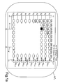
- each PV system 1,1 has eight fields F 1 to F 8 or F 1' to F 8 , whose designation is preceded by the prefix A 1 for system 1 or A 2 for system 2 , In detail, only the first plant A 1 is discussed.
- the first plant A 1 has eight fields A 1 F 1 , A 1 F 2 , ... to A 1 F 8 which in turn are all the same structure.
- each plant field AF has ten electrically parallel strands S, which are numbered S 1 to S 10 .
- Each strand S 1 to S 10 in turn has a series connection of 10 PV modules M, which in turn are numbered M 1 to M 10 .
- a single one of the one hundred PV modules S 1 M 1 to S 10 M 10 is designed fully black, namely the photovoltaic module S 3 M 3 which is assumed to be defective.
- Each module M consists of about 60 PV cells connected in series.
- the PV cell is the smallest unit in which the sun's rays are converted into electricity.
- the 60 cells are connected in series, so that at a working voltage of 1 volt per cell, a voltage of 60 volts builds up across the module.
- the voltage across the entire strand also referred to as strand voltage, is 600 volts.
- the device has two current clamps 5 and 7, which are suitable to one of the two electrical leads 9,9 'of the fields F, one of the two leads 11,11' to the strands S or one of the two leads 13,13 'to a Inverter WR to be installed.
- Such current clamps for the measurement of direct currents are well known.
- the current clamps 5.7 are connected to an evaluation unit 15, which will be discussed later.
- the procedure for identifying the defective strand S 3 will be explained. For reasons of clarity, it is assumed that all PV modules M work the same and perfect otherwise.
- the first current clamp 5 is placed around one of the supply lines 13, 13 'to the first inverter WR 1
- the second current clamp 7 is placed around one of the supply lines 13, 13' of the inverter WR 2 . Since the system A 1 has the defective module, it will generate less power and thus power than the PV system A 2 .
- the working voltage U 1 and U 2 of the two inverters WR 1 and WR 2 must be set to the same voltage value. This is done via an intervention on the MPP controller, as is common in the field of solar technology. By this first step is thus determined that the error that leads to a reduction in performance, must lie in the plant part A 2 .
- both currents measured at the same time are the same, the associated fields A 1 F 1 and A 1 F 2 must also be the same, ie there is normally undisturbed power generation. The case that both fields A 1 F 1 and A 1 F 2 have the same error is very unlikely and is currently being discussed. not considered further.
- one of the current clamps 5, 5 is placed around one of the supply lines 9, 9 'of the second field A 1 F 2 and the other current clamp 7 around one of the supply lines 9, 9' of the third field A 1, F 3 .
- the current clamp 5 .7 which was previously located at the first field A 1 F 1 , is converted to the third field A 1 F 3 .
- the damaged in the third strand S 3 module S 3 M 3 is preferably measured at night, when the PV system is switched off due to the high strand voltage. This takes place, for example, by disconnecting the plug connection between the fifth module S 3 M 5 and the sixth module S 3 M 6 , in order then to check half of the third line S 3 for an interruption. After determining that the interruption must be in the first five modules S 3 M, to S 3 M 5 , the connector between the modules S 3 M 3 and S 3 M 4 can be solved. The subsequent current flow measurement would detect the error in the first part of the modules S 1 M 1 to S 3 M 3 , which would then be examined individually for interruption in the current-carrying path.
- the individual power of each field F 1 to F 8 can be made via a single current measurement.
- the current measurement can be stationary at a fixed to one of the fields F installed power meter or with a mobile device, such as that of the present device.
- This requires that all PV units are connected to the same inverter, which is kept at a constant voltage during all DC measurements, in particular by fixing the MPP (Maximum Power Point) controller of the inverter WR to the constant voltage value.
- MPP Maximum Power Point
- the fields are connected to the same inverter WR 1 , (FIG. or to the adjusted voltage with multiple inverters) and thus at the same voltage.
- the present current is measured at one of the PV units and in a further evaluation unit from the present current value and the ratioed stored measured values the total current or, taking into account the respective operating voltage values of PV units, the total power of the photovoltaic system determined.
- the connecting or supply lines 9,9 ', 11,11'; 13,13 ' can be close to each other or even a greater distance apart.
- no separate bus line is formed in the fields F, but the connecting lines 9, 9 ', 11, 11'; 13,13 'are individually led to the inverter WR and run there, for example, in a cabinet together.
- the associated connection lines can easily be identified by inspection. Particularly in the case of a repeat measurement at a later time, it is necessary to know which of the connection lines 9, 9 ', 11, 11'; 13,13 'the current clamps are to be placed 5.7. Therefore, it makes sense to store an information identifying the location of the measurement together with the current measurement pair or the ratio.
- an RFID chip also fulfills its task, which is fastened to a support of the considered field F and only releases the repeated measurement when the measuring device is at the location predetermined by the RFID chip.
- the distance between the measuring points must be large enough so that the transponder-like working chips can be clearly distinguished.
- a barcode makes sense, which is located on one of the connection lines 9, 9 ', 11, 11'; 13,13 'label is located. The label can be glued directly to the connecting cable.
- the bar code is then registered by means of a suitable reading device and stored with the current value pair or the ratio.
- the measured values of each pair, together with the identification and possibly the present operating voltage, can also be sent wirelessly to a data processing center, where the ratio formation, the performance determination, the determination for defects, etc. are then carried out.
- the current values provided by the measurement data acquisition unit are not directly processed, but a plurality of measurements are made short, i.e., short. within a few seconds or fractions of a second. Subsequently, the arithmetic mean is formed, which can then be used for further processing, such as ratioing.
- the current clamp 5 is placed around the connecting line 9 'of the field A 1 F 2 and the other clamp 7 to the connection line 9 of the field F A 1.
- the current clamps 5,7 are standard current clamps, which are provided with a handle part, to allow easy and quick change.
- the device comprises a selector switch 15, which specifies the measuring range required for the current measurement. This is in the position A for the power of the system, for example, 1000 amps, for the position F for the current of a field, for example, 100 amps and in the position S for the current measurement on a string about 10 amps. Of the current clamps 5,7 lead each two lines 17a, 17b away, leading to the measurement data acquisition unit 3.
- the identification of the measuring location or of the measuring point MS is output to the measuring data acquisition unit 3 by a receiver 19, which records the location data of position registration means.
- a bar code 21 is preferably used with small spacing of the lines 9, 9 'between the fields A 1 F 1 to A 1 F 8 , the receiver 19 then being a bar code reader.
- the bar code 21 can be attached directly to the lines 9,9 '.
- an RFID tag 21a is useful, which is located in the vicinity of the measuring point MS, for example present between the fields A 1 F 2 and A 1 F 3 on the support frame (not shown) of the PV modules M is appropriate.
- the RFID tag 21a has a reception or reaction range of, for example, 2 meters and registers via a transponder function when the measurement data acquisition unit 3 is in its vicinity. Will be served during the stay of Unit 3 within the Communication range of the RFID - 21 a label carried out a measurement, the measured current values of the current pair I 2 and I 3 are forwarded together with the identification of the measuring point MS 2-3 to an evaluation unit 23 or via antenna 25 wirelessly to an external data processing 27.
- GPS positioning can also be carried out together with the measured value acquisition I 2 , I 3 , and the coordinates of the location are combined directly with the current value pair I 2 , I 3 to form a single data record.
- the evaluation unit 23 comprises a ratio former 29 which, from the measured current values I 2 and I 3, forms the ratio, ie I 2 / I 3 , which is applied as an output signal S 1 to the first input of a comparator or a comparison unit 31.
- a reference ratio V ref is set, which has resulted from an arbitrary, earlier measurement than the day of the currently performed measurement, in particular to the day of commissioning. If the current ratio I 2 / I 3 deviates from one another by a predefinable amount, for example 5%, an irregularity in the performance of one of the fields A 1 F 2 or A 1 F 3 may already be inferred here.
- the ratio I 2 / I 3 is greater than 1, the field A 1 F 3 must have a lower current than expected. Conversely, at a ratio I 2 / I 3 less than 1, the field A 1 F 2 results in a lower than expected current.
- a comparison can also be made with the last registered ratio V for this current pair.
- the comparator 31 has a further input to which a signal s 2 is applied, which is read out of a memory element 33 for the ratios V. This comparison allows an assessment of the degradation or of the error occurrence for the last measurement and not with the reference value V ref formed during commissioning, for example, which was stored in a separate memory 35 for the reference values V ref .
- the storage element 33 for the ratios V is also supplied with the signal s 1 from the ratio images 29.
- the storage element 33 for the ratios V is furthermore connected via a signal line s 3 to a linking element 37 which, in an analogous manner as previously combined with the measured current values I 2 , I 3 with the position data of the measuring point in the measured data evaluation unit 3, these positions data also associated with the associated ratios V.
- a linking element 37 which, in an analogous manner as previously combined with the measured current values I 2 , I 3 with the position data of the measuring point in the measured data evaluation unit 3, these positions data also associated with the associated ratios V.
- the logic element 37 are then on a signal line s 4, the ratios V together with the identification of the measuring point MS.
- the linked data pairs of ratio V on the one hand and measuring point MS on the other hand are stored in a separate data storage element 38.
- a stationary current measuring point 41 which permanently or on request measures the measured current, possibly with the associated field voltage.
- the stationary current measuring point 41 can be usefully grown on the field F, which has demonstrated the best performance of all fields after the establishment of the system.
- the steady-state measured current can be used as the reference current I ref equal, at which an assessment of the generated power of all other fields F can be made.
- a further memory element 43 is connected, in which the results of the multiplication for further use, eg for calculating the theoretical power of any fields F, are stored.
- the current I 3 of the field A 1 F3 with the defective module S 3 M 3 can be determined be by the current I 1 of the first field F 1 is multiplied by the two ratios V 1-2 and V 2-3 and, if several inverters WR are present, multiplied by the voltage of the connected inverter WR to determine the power. Due to the defective module M, the ratio VF 2-3 is higher than in the normal case and thus reflects the already known, lower current I 3 again. In this way, all fields F which have previously been encountered can be examined and the sum of the lower power of all defective fields F can be calculated with only one current measurement per system A.
- the ratio V to the leading and trailing strand S or field F would be defined as infinity and zero, respectively.
- any ratio of zero or infinity is masked out and, consequently, a ratio V is formed from the directly preceding and following strand S or field F.
- the current values I 2 and I 3 can also be applied directly to a comparison part 45, which directly compares the currents I 2 , I 3 with reference currents that correspond to measured and saved at an earlier point in time.
- the current pair value I 2 , I 3 are applied to the input of a power comparator 47, the other input for the value of the voltage U 1 at the inverter WR 1 , or in the presence of several inverters also correspondingly many inputs for the operating voltage value U of the respective WR.
- an input is provided at the power comparator 47, at which a signal s 5 , which reflects the reference power P ref either of the reference PV unit, ie present the reference field F 4 , or the power of previous measurements, applied as a comparison reference signal.
- the power comparator 47 has an output 49 in which a warning signal can be tapped in the case of an impermissibly high deviation from the comparison reference value or from the power value with one another.
- FIG. 2 is still shown a computing unit 49 which is connected to the evaluation unit 3 and from this with the multiplied current values I 1 , (I 1 * V 1-2 ), (I 1 * V 2-3 ), (I 1 * V 3 -4 ), .... (I 1 * V 7-8 ) is supplied (* corresponds to a multiplication).
- the currents of all fields F are added and given as a value of the total current I tot of the system A 1 to another multiplier 51, in which still the voltage value U of the reference field, in the example of the field F 4 , is entered.
- the output signal s 6 of the further multiplier 51 is the theoretically present power P theoretical , which is displayed on a display 53.
- the real instantaneous power P real determined via the actual current measured at the inverter WR can be displayed on the display 53, so that a continuous visual comparison of the present power P with the theoretically expected power is possible.
- the housing of the device 1 which has an integrated direct current source 55 inside, which feeds a line 59 with a calibration current I calibrated via a measuring shunt 57.
- the conduit 59 extends partially through the interior of a bracket 61 which is integrally formed on the housing.
- the bracket 61 and the line 59 are dimensioned so that they can be enclosed by the two current clamps 5.7 simultaneously.
- a switch 63 closes the calibration circuit.
- the switch 63 is preferably provided as a push button or lever on the housing surface.
- the above-described calibration via the measuring shunt 57 serves to specify the absolute measured value and is therefore preferable to the calibration with one another.
Landscapes
- Photovoltaic Devices (AREA)
- Testing Of Individual Semiconductor Devices (AREA)
Applications Claiming Priority (1)
| Application Number | Priority Date | Filing Date | Title |
|---|---|---|---|
| DE102009048691A DE102009048691A1 (de) | 2009-10-08 | 2009-10-08 | Gleichstrommessstelle zum Auffinden defekter PV-Module in einer PV-Anlage |
Publications (3)
| Publication Number | Publication Date |
|---|---|
| EP2317329A2 true EP2317329A2 (fr) | 2011-05-04 |
| EP2317329A3 EP2317329A3 (fr) | 2013-04-03 |
| EP2317329B1 EP2317329B1 (fr) | 2016-05-25 |
Family
ID=43513580
Family Applications (1)
| Application Number | Title | Priority Date | Filing Date |
|---|---|---|---|
| EP10009607.2A Not-in-force EP2317329B1 (fr) | 2009-10-08 | 2010-09-15 | Poste à courant continu destiné à trouver des modules PV défectueux dans une installation photovoltaïque |
Country Status (5)
| Country | Link |
|---|---|
| US (1) | US20110241720A1 (fr) |
| EP (1) | EP2317329B1 (fr) |
| DE (1) | DE102009048691A1 (fr) |
| ES (1) | ES2584185T3 (fr) |
| PL (1) | PL2317329T3 (fr) |
Cited By (2)
| Publication number | Priority date | Publication date | Assignee | Title |
|---|---|---|---|---|
| EP2664939A1 (fr) * | 2012-05-18 | 2013-11-20 | Skytron Energy GmbH | Procédé de validation de valeurs de mesure en fonction de la position du soleil sur plusieurs canaux de mesure |
| CN109298228A (zh) * | 2018-09-13 | 2019-02-01 | 安徽天尚清洁能源科技有限公司 | 一种基于光伏组串电流异常的智能化诊断方法及系统 |
Families Citing this family (6)
| Publication number | Priority date | Publication date | Assignee | Title |
|---|---|---|---|---|
| DE102012024544A1 (de) | 2011-12-28 | 2013-07-04 | Phoenix Contact Gmbh & Co. Kg | Photovoltaikanlage und Überwachungseinheit zur Erfassung des Leistungsabfalls in einem String einer Photovoltaikanlage |
| CN102565663B (zh) * | 2012-01-17 | 2014-07-02 | 天津大学 | 一种光伏阵列故障诊断的方法 |
| WO2013148215A1 (fr) * | 2012-03-29 | 2013-10-03 | Ampt, Llc | Procédés et appareil de gestion de données de système photovoltaïque |
| US10598703B2 (en) * | 2015-07-20 | 2020-03-24 | Eaton Intelligent Power Limited | Electric fuse current sensing systems and monitoring methods |
| US11456698B2 (en) | 2020-02-28 | 2022-09-27 | University Of Cyprus | Early detection of potential induced degradation in photovoltaic systems |
| DE102021130817A1 (de) * | 2021-11-24 | 2023-05-25 | Wavelabs Solar Metrology Systems Gmbh | Energieautarke PV-Kennlinienmesssung |
Family Cites Families (16)
| Publication number | Priority date | Publication date | Assignee | Title |
|---|---|---|---|---|
| US583934A (en) * | 1897-06-08 | Shunt-ammeter | ||
| US3793166A (en) * | 1970-01-07 | 1974-02-19 | American Smelting Refining | Electrical current measurement and rapidly locating and positively identifying cathodes having abnormal electrical conditions associated therewith in an electrolytic copper refining process tankhouse |
| DE2843026A1 (de) * | 1978-10-03 | 1980-04-24 | Bosch Gmbh Robert | Strommessgeraet mit einer stromzange |
| DE3040316C2 (de) * | 1980-10-25 | 1983-11-10 | Grundig E.M.V. Elektro-Mechanische Versuchsanstalt Max Grundig & Co KG, 8510 Fürth | Verfahren und Vorrichtung zur kontaktlosen Messung von Gleich- und Wechselströmen, insbesondere von Strom-Augenblickswerten |
| US4528503A (en) * | 1981-03-19 | 1985-07-09 | The United States Of America As Represented By The Department Of Energy | Method and apparatus for I-V data acquisition from solar cells |
| US5669987A (en) * | 1994-04-13 | 1997-09-23 | Canon Kabushiki Kaisha | Abnormality detection method, abnormality detection apparatus, and solar cell power generating system using the same |
| JP2874156B2 (ja) * | 1994-04-13 | 1999-03-24 | キヤノン株式会社 | 発電システム |
| DE19914336A1 (de) * | 1999-03-30 | 2000-10-05 | Metrawatt Gmbh Gossen | Strommeßgerät |
| US6724180B1 (en) * | 2002-06-11 | 2004-04-20 | Neal R. Verfuerth | Apparatus for and method of metering separate lighting circuits for comparative electric power usage to provide a virtual power plant in electric power savings |
| RU2222858C1 (ru) * | 2002-10-31 | 2004-01-27 | Механошин Борис Иосифович | Устройство для дистанционного контроля состояния провода воздушной линии электропередачи (варианты) |
| JP2005340464A (ja) * | 2004-05-26 | 2005-12-08 | Sharp Corp | 太陽電池アレイ診断装置およびそれを用いた太陽光発電システム |
| US8204709B2 (en) * | 2005-01-18 | 2012-06-19 | Solar Sentry Corporation | System and method for monitoring photovoltaic power generation systems |
| EP1931690A2 (fr) * | 2005-10-04 | 2008-06-18 | Thompson Technology Industrie, Inc. | Systeme et methode pour une surveillance de niveau d'agencement et de corde d'un systeme de puissance photovoltaique relie a une grille |
| DE102007044166B4 (de) * | 2006-09-18 | 2010-07-01 | Ralf Scherber | Anordnung zur Messung von Stromertrags- und/oder Verbrauchsgrößen in einem Niederspannungsnetz nebst zugehörigem Verfahren |
| US8423308B2 (en) * | 2007-11-01 | 2013-04-16 | Leviton Mfg. Co. | Multi-circuit direct current monitor with Modbus serial output |
| US20100142583A1 (en) * | 2008-09-12 | 2010-06-10 | Thor Manuel Christensen | System, method, and apparatus for the calibration of analog type thermometers for use in providing temperature quality control in the production of beverage and/or food products |
-
2009
- 2009-10-08 DE DE102009048691A patent/DE102009048691A1/de not_active Withdrawn
-
2010
- 2010-09-15 EP EP10009607.2A patent/EP2317329B1/fr not_active Not-in-force
- 2010-09-15 ES ES10009607.2T patent/ES2584185T3/es active Active
- 2010-09-15 PL PL10009607.2T patent/PL2317329T3/pl unknown
- 2010-10-06 US US12/899,136 patent/US20110241720A1/en not_active Abandoned
Non-Patent Citations (1)
| Title |
|---|
| None |
Cited By (3)
| Publication number | Priority date | Publication date | Assignee | Title |
|---|---|---|---|---|
| US9644958B2 (en) | 2012-03-18 | 2017-05-09 | Skytron Energy Gmbh | Method for the validation of solar altitude-dependent measured values of several measurement channels |
| EP2664939A1 (fr) * | 2012-05-18 | 2013-11-20 | Skytron Energy GmbH | Procédé de validation de valeurs de mesure en fonction de la position du soleil sur plusieurs canaux de mesure |
| CN109298228A (zh) * | 2018-09-13 | 2019-02-01 | 安徽天尚清洁能源科技有限公司 | 一种基于光伏组串电流异常的智能化诊断方法及系统 |
Also Published As
| Publication number | Publication date |
|---|---|
| PL2317329T3 (pl) | 2016-11-30 |
| ES2584185T3 (es) | 2016-09-26 |
| EP2317329A3 (fr) | 2013-04-03 |
| US20110241720A1 (en) | 2011-10-06 |
| EP2317329B1 (fr) | 2016-05-25 |
| DE102009048691A1 (de) | 2011-04-21 |
Similar Documents
| Publication | Publication Date | Title |
|---|---|---|
| EP2317329B1 (fr) | Poste à courant continu destiné à trouver des modules PV défectueux dans une installation photovoltaïque | |
| DE102010009079B4 (de) | Verfahren und Vorrichtung zum Auffinden leistungsschwacher PV-Module in einer PV-Anlage mittels des Einsatzes von Trennschaltern | |
| DE102010009080B4 (de) | Verfahren und Vorrichtung zum Auffinden leistungsschwacher PV-Module in einer PV-Anlage | |
| DE102008008504A1 (de) | Verfahren zur Diebstahlerkennung eines PV-Moduls und zur Ausfallerkennung einer Bypassdiode eines PV-Moduls sowie dazu korrespondierender PV-Teilgenerator-Anschlusskasten, PV-Wechselrichter und dazu korrespondierende PV-Anlage | |
| DE102017209243B4 (de) | Verfahren und Messanordnung zur Überwachung eines Fertigungsablaufs einer modular aufgebauten Spannungsquelle | |
| WO2017085174A1 (fr) | Procédé et dispositif de détection de défauts dans un générateur photovoltaïque (pv) | |
| DE102012219690A1 (de) | Spannungsquellenanordnung und verfahren zur diagnose einer spannungsquellenanordnung | |
| DE102011083307A1 (de) | Vorrichtung zur Messung eines Batteriestroms | |
| DE102011003308A1 (de) | Überwachungsanordnung und Verfahren zur Überwachung einer elektrischen Leitung | |
| WO2011032993A1 (fr) | Procédé et dispositif pour la caractérisation d'au moins un module de cellules solaires | |
| EP2399177B1 (fr) | Procédé et dispositif de surveillance d'une installation photovoltaïque | |
| EP2950446B1 (fr) | Procédé de détection d'un degré de salissure de panneaux pv | |
| EP2044451B1 (fr) | Installation photovoltaïque | |
| DE102010037582A1 (de) | Verfahren zur Bestimmung einer räumlichen Anordnung von Photovoltaikmodulgruppen einer Photovoltaikanlage | |
| EP3289657A1 (fr) | Procédé de vérification des phases pour des modules solaires d'une installation photovoltaïque et onduleur photovoltaïque pour l'exécution du procédé | |
| DE102014206454B4 (de) | Verfahren und Vorrichtung zum Überprüfen einer Anordnung mit einer Anzahl von Solarmodulen | |
| EP1925923B1 (fr) | Procédé et dispositif de détermination de valeurs de mesure caractéristiques pour la force de rayonnement solaire sur le site d'un générateur PV | |
| DE102010010509A1 (de) | Verfahren zur Identifizierung leistungsschwacher Photovoltaikmodule in einer bestehenden PV-Anlage | |
| EP2910903A1 (fr) | Procédé de détection du vol de courant dans un réseau basse tension | |
| DE102012025178A1 (de) | Verfahren und Vorrichtung zur automatischen Charakterisierung und Überwachung eines elektrischen Netzes oder eines Stromnetzabschnitts eines elektrischen Netzes oder einer elektrischen Anlage | |
| EP2664939B1 (fr) | Procédé de validation de valeurs de mesure en fonction de la position du soleil sur plusieurs canaux de mesure | |
| EP2839303B1 (fr) | Procédé de détermination de la capacité de puissance d'installations photovoltaïques | |
| EP3407035B1 (fr) | Dispositif de mesure et procédé de mesure de la répartition de l'intensité d'un rayon de lumière incidente | |
| WO2023094555A1 (fr) | Dispositif de test de module solaire et procédé de test de module solaire | |
| DE102009049777A1 (de) | Auswertesystem für Photovoltaikmodule |
Legal Events
| Date | Code | Title | Description |
|---|---|---|---|
| PUAI | Public reference made under article 153(3) epc to a published international application that has entered the european phase |
Free format text: ORIGINAL CODE: 0009012 |
|
| AK | Designated contracting states |
Kind code of ref document: A2 Designated state(s): AL AT BE BG CH CY CZ DE DK EE ES FI FR GB GR HR HU IE IS IT LI LT LU LV MC MK MT NL NO PL PT RO SE SI SK SM TR |
|
| AX | Request for extension of the european patent |
Extension state: BA ME RS |
|
| PUAL | Search report despatched |
Free format text: ORIGINAL CODE: 0009013 |
|
| AK | Designated contracting states |
Kind code of ref document: A3 Designated state(s): AL AT BE BG CH CY CZ DE DK EE ES FI FR GB GR HR HU IE IS IT LI LT LU LV MC MK MT NL NO PL PT RO SE SI SK SM TR |
|
| AX | Request for extension of the european patent |
Extension state: BA ME RS |
|
| RIC1 | Information provided on ipc code assigned before grant |
Ipc: G01R 31/40 20060101AFI20130226BHEP |
|
| 17P | Request for examination filed |
Effective date: 20130902 |
|
| RBV | Designated contracting states (corrected) |
Designated state(s): AL AT BE BG CH CY CZ DE DK EE ES FI FR GB GR HR HU IE IS IT LI LT LU LV MC MK MT NL NO PL PT RO SE SI SK SM TR |
|
| 17Q | First examination report despatched |
Effective date: 20150401 |
|
| REG | Reference to a national code |
Ref country code: DE Ref legal event code: R079 Ref document number: 502010011723 Country of ref document: DE Free format text: PREVIOUS MAIN CLASS: G01R0031260000 Ipc: H02S0050100000 |
|
| GRAP | Despatch of communication of intention to grant a patent |
Free format text: ORIGINAL CODE: EPIDOSNIGR1 |
|
| RIC1 | Information provided on ipc code assigned before grant |
Ipc: H02S 50/10 20140101AFI20150908BHEP |
|
| INTG | Intention to grant announced |
Effective date: 20151002 |
|
| INTG | Intention to grant announced |
Effective date: 20160105 |
|
| INTG | Intention to grant announced |
Effective date: 20160226 |
|
| GRAS | Grant fee paid |
Free format text: ORIGINAL CODE: EPIDOSNIGR3 |
|
| GRAA | (expected) grant |
Free format text: ORIGINAL CODE: 0009210 |
|
| AK | Designated contracting states |
Kind code of ref document: B1 Designated state(s): AL AT BE BG CH CY CZ DE DK EE ES FI FR GB GR HR HU IE IS IT LI LT LU LV MC MK MT NL NO PL PT RO SE SI SK SM TR |
|
| REG | Reference to a national code |
Ref country code: GB Ref legal event code: FG4D Free format text: NOT ENGLISH |
|
| REG | Reference to a national code |
Ref country code: CH Ref legal event code: EP |
|
| REG | Reference to a national code |
Ref country code: IE Ref legal event code: FG4D Free format text: LANGUAGE OF EP DOCUMENT: GERMAN Ref country code: AT Ref legal event code: REF Ref document number: 803056 Country of ref document: AT Kind code of ref document: T Effective date: 20160615 |
|
| REG | Reference to a national code |
Ref country code: DE Ref legal event code: R096 Ref document number: 502010011723 Country of ref document: DE |
|
| REG | Reference to a national code |
Ref country code: NL Ref legal event code: FP |
|
| REG | Reference to a national code |
Ref country code: FR Ref legal event code: PLFP Year of fee payment: 7 |
|
| REG | Reference to a national code |
Ref country code: ES Ref legal event code: FG2A Ref document number: 2584185 Country of ref document: ES Kind code of ref document: T3 Effective date: 20160926 Ref country code: LT Ref legal event code: MG4D |
|
| PG25 | Lapsed in a contracting state [announced via postgrant information from national office to epo] |
Ref country code: NO Free format text: LAPSE BECAUSE OF FAILURE TO SUBMIT A TRANSLATION OF THE DESCRIPTION OR TO PAY THE FEE WITHIN THE PRESCRIBED TIME-LIMIT Effective date: 20160825 Ref country code: FI Free format text: LAPSE BECAUSE OF FAILURE TO SUBMIT A TRANSLATION OF THE DESCRIPTION OR TO PAY THE FEE WITHIN THE PRESCRIBED TIME-LIMIT Effective date: 20160525 Ref country code: LT Free format text: LAPSE BECAUSE OF FAILURE TO SUBMIT A TRANSLATION OF THE DESCRIPTION OR TO PAY THE FEE WITHIN THE PRESCRIBED TIME-LIMIT Effective date: 20160525 |
|
| PG25 | Lapsed in a contracting state [announced via postgrant information from national office to epo] |
Ref country code: HR Free format text: LAPSE BECAUSE OF FAILURE TO SUBMIT A TRANSLATION OF THE DESCRIPTION OR TO PAY THE FEE WITHIN THE PRESCRIBED TIME-LIMIT Effective date: 20160525 Ref country code: GR Free format text: LAPSE BECAUSE OF FAILURE TO SUBMIT A TRANSLATION OF THE DESCRIPTION OR TO PAY THE FEE WITHIN THE PRESCRIBED TIME-LIMIT Effective date: 20160826 Ref country code: PT Free format text: LAPSE BECAUSE OF FAILURE TO SUBMIT A TRANSLATION OF THE DESCRIPTION OR TO PAY THE FEE WITHIN THE PRESCRIBED TIME-LIMIT Effective date: 20160926 Ref country code: LV Free format text: LAPSE BECAUSE OF FAILURE TO SUBMIT A TRANSLATION OF THE DESCRIPTION OR TO PAY THE FEE WITHIN THE PRESCRIBED TIME-LIMIT Effective date: 20160525 Ref country code: SE Free format text: LAPSE BECAUSE OF FAILURE TO SUBMIT A TRANSLATION OF THE DESCRIPTION OR TO PAY THE FEE WITHIN THE PRESCRIBED TIME-LIMIT Effective date: 20160525 |
|
| PG25 | Lapsed in a contracting state [announced via postgrant information from national office to epo] |
Ref country code: RO Free format text: LAPSE BECAUSE OF FAILURE TO SUBMIT A TRANSLATION OF THE DESCRIPTION OR TO PAY THE FEE WITHIN THE PRESCRIBED TIME-LIMIT Effective date: 20160525 Ref country code: CZ Free format text: LAPSE BECAUSE OF FAILURE TO SUBMIT A TRANSLATION OF THE DESCRIPTION OR TO PAY THE FEE WITHIN THE PRESCRIBED TIME-LIMIT Effective date: 20160525 Ref country code: EE Free format text: LAPSE BECAUSE OF FAILURE TO SUBMIT A TRANSLATION OF THE DESCRIPTION OR TO PAY THE FEE WITHIN THE PRESCRIBED TIME-LIMIT Effective date: 20160525 Ref country code: DK Free format text: LAPSE BECAUSE OF FAILURE TO SUBMIT A TRANSLATION OF THE DESCRIPTION OR TO PAY THE FEE WITHIN THE PRESCRIBED TIME-LIMIT Effective date: 20160525 Ref country code: SK Free format text: LAPSE BECAUSE OF FAILURE TO SUBMIT A TRANSLATION OF THE DESCRIPTION OR TO PAY THE FEE WITHIN THE PRESCRIBED TIME-LIMIT Effective date: 20160525 |
|
| PG25 | Lapsed in a contracting state [announced via postgrant information from national office to epo] |
Ref country code: SM Free format text: LAPSE BECAUSE OF FAILURE TO SUBMIT A TRANSLATION OF THE DESCRIPTION OR TO PAY THE FEE WITHIN THE PRESCRIBED TIME-LIMIT Effective date: 20160525 Ref country code: BE Free format text: LAPSE BECAUSE OF NON-PAYMENT OF DUE FEES Effective date: 20160930 |
|
| REG | Reference to a national code |
Ref country code: DE Ref legal event code: R097 Ref document number: 502010011723 Country of ref document: DE |
|
| PLBE | No opposition filed within time limit |
Free format text: ORIGINAL CODE: 0009261 |
|
| STAA | Information on the status of an ep patent application or granted ep patent |
Free format text: STATUS: NO OPPOSITION FILED WITHIN TIME LIMIT |
|
| PG25 | Lapsed in a contracting state [announced via postgrant information from national office to epo] |
Ref country code: MC Free format text: LAPSE BECAUSE OF FAILURE TO SUBMIT A TRANSLATION OF THE DESCRIPTION OR TO PAY THE FEE WITHIN THE PRESCRIBED TIME-LIMIT Effective date: 20160525 |
|
| REG | Reference to a national code |
Ref country code: CH Ref legal event code: PL |
|
| 26N | No opposition filed |
Effective date: 20170228 |
|
| PG25 | Lapsed in a contracting state [announced via postgrant information from national office to epo] |
Ref country code: SI Free format text: LAPSE BECAUSE OF FAILURE TO SUBMIT A TRANSLATION OF THE DESCRIPTION OR TO PAY THE FEE WITHIN THE PRESCRIBED TIME-LIMIT Effective date: 20160525 |
|
| REG | Reference to a national code |
Ref country code: IE Ref legal event code: MM4A |
|
| PG25 | Lapsed in a contracting state [announced via postgrant information from national office to epo] |
Ref country code: LI Free format text: LAPSE BECAUSE OF NON-PAYMENT OF DUE FEES Effective date: 20160930 Ref country code: IE Free format text: LAPSE BECAUSE OF NON-PAYMENT OF DUE FEES Effective date: 20160915 Ref country code: CH Free format text: LAPSE BECAUSE OF NON-PAYMENT OF DUE FEES Effective date: 20160930 |
|
| PG25 | Lapsed in a contracting state [announced via postgrant information from national office to epo] |
Ref country code: IT Free format text: LAPSE BECAUSE OF NON-PAYMENT OF DUE FEES Effective date: 20160915 Ref country code: LU Free format text: LAPSE BECAUSE OF NON-PAYMENT OF DUE FEES Effective date: 20160915 |
|
| REG | Reference to a national code |
Ref country code: FR Ref legal event code: PLFP Year of fee payment: 8 |
|
| REG | Reference to a national code |
Ref country code: AT Ref legal event code: MM01 Ref document number: 803056 Country of ref document: AT Kind code of ref document: T Effective date: 20160915 |
|
| REG | Reference to a national code |
Ref country code: BE Ref legal event code: MM Effective date: 20160930 |
|
| PGFP | Annual fee paid to national office [announced via postgrant information from national office to epo] |
Ref country code: PL Payment date: 20170911 Year of fee payment: 8 |
|
| PG25 | Lapsed in a contracting state [announced via postgrant information from national office to epo] |
Ref country code: AT Free format text: LAPSE BECAUSE OF NON-PAYMENT OF DUE FEES Effective date: 20160915 |
|
| PG25 | Lapsed in a contracting state [announced via postgrant information from national office to epo] |
Ref country code: CY Free format text: LAPSE BECAUSE OF FAILURE TO SUBMIT A TRANSLATION OF THE DESCRIPTION OR TO PAY THE FEE WITHIN THE PRESCRIBED TIME-LIMIT Effective date: 20160525 Ref country code: HU Free format text: LAPSE BECAUSE OF FAILURE TO SUBMIT A TRANSLATION OF THE DESCRIPTION OR TO PAY THE FEE WITHIN THE PRESCRIBED TIME-LIMIT; INVALID AB INITIO Effective date: 20100915 |
|
| PG25 | Lapsed in a contracting state [announced via postgrant information from national office to epo] |
Ref country code: MK Free format text: LAPSE BECAUSE OF FAILURE TO SUBMIT A TRANSLATION OF THE DESCRIPTION OR TO PAY THE FEE WITHIN THE PRESCRIBED TIME-LIMIT Effective date: 20160525 Ref country code: TR Free format text: LAPSE BECAUSE OF FAILURE TO SUBMIT A TRANSLATION OF THE DESCRIPTION OR TO PAY THE FEE WITHIN THE PRESCRIBED TIME-LIMIT Effective date: 20160525 Ref country code: IS Free format text: LAPSE BECAUSE OF FAILURE TO SUBMIT A TRANSLATION OF THE DESCRIPTION OR TO PAY THE FEE WITHIN THE PRESCRIBED TIME-LIMIT Effective date: 20160525 Ref country code: MT Free format text: LAPSE BECAUSE OF FAILURE TO SUBMIT A TRANSLATION OF THE DESCRIPTION OR TO PAY THE FEE WITHIN THE PRESCRIBED TIME-LIMIT Effective date: 20160525 |
|
| PG25 | Lapsed in a contracting state [announced via postgrant information from national office to epo] |
Ref country code: BG Free format text: LAPSE BECAUSE OF FAILURE TO SUBMIT A TRANSLATION OF THE DESCRIPTION OR TO PAY THE FEE WITHIN THE PRESCRIBED TIME-LIMIT Effective date: 20160525 |
|
| REG | Reference to a national code |
Ref country code: FR Ref legal event code: PLFP Year of fee payment: 9 |
|
| PG25 | Lapsed in a contracting state [announced via postgrant information from national office to epo] |
Ref country code: AL Free format text: LAPSE BECAUSE OF FAILURE TO SUBMIT A TRANSLATION OF THE DESCRIPTION OR TO PAY THE FEE WITHIN THE PRESCRIBED TIME-LIMIT Effective date: 20160525 |
|
| PGFP | Annual fee paid to national office [announced via postgrant information from national office to epo] |
Ref country code: NL Payment date: 20190923 Year of fee payment: 10 Ref country code: FR Payment date: 20190923 Year of fee payment: 10 |
|
| PGFP | Annual fee paid to national office [announced via postgrant information from national office to epo] |
Ref country code: GB Payment date: 20190924 Year of fee payment: 10 |
|
| PGFP | Annual fee paid to national office [announced via postgrant information from national office to epo] |
Ref country code: DE Payment date: 20190923 Year of fee payment: 10 |
|
| PGFP | Annual fee paid to national office [announced via postgrant information from national office to epo] |
Ref country code: ES Payment date: 20191023 Year of fee payment: 10 |
|
| PG25 | Lapsed in a contracting state [announced via postgrant information from national office to epo] |
Ref country code: PL Free format text: LAPSE BECAUSE OF NON-PAYMENT OF DUE FEES Effective date: 20180915 |
|
| REG | Reference to a national code |
Ref country code: DE Ref legal event code: R082 Ref document number: 502010011723 Country of ref document: DE |
|
| REG | Reference to a national code |
Ref country code: DE Ref legal event code: R119 Ref document number: 502010011723 Country of ref document: DE |
|
| REG | Reference to a national code |
Ref country code: NL Ref legal event code: MM Effective date: 20201001 |
|
| GBPC | Gb: european patent ceased through non-payment of renewal fee |
Effective date: 20200915 |
|
| PG25 | Lapsed in a contracting state [announced via postgrant information from national office to epo] |
Ref country code: NL Free format text: LAPSE BECAUSE OF NON-PAYMENT OF DUE FEES Effective date: 20201001 |
|
| PG25 | Lapsed in a contracting state [announced via postgrant information from national office to epo] |
Ref country code: FR Free format text: LAPSE BECAUSE OF NON-PAYMENT OF DUE FEES Effective date: 20200930 Ref country code: DE Free format text: LAPSE BECAUSE OF NON-PAYMENT OF DUE FEES Effective date: 20210401 |
|
| PG25 | Lapsed in a contracting state [announced via postgrant information from national office to epo] |
Ref country code: GB Free format text: LAPSE BECAUSE OF NON-PAYMENT OF DUE FEES Effective date: 20200915 |
|
| REG | Reference to a national code |
Ref country code: ES Ref legal event code: FD2A Effective date: 20220118 |
|
| PG25 | Lapsed in a contracting state [announced via postgrant information from national office to epo] |
Ref country code: ES Free format text: LAPSE BECAUSE OF NON-PAYMENT OF DUE FEES Effective date: 20200916 |