EP2317329A2 - Direct current metering point for detecting defective PV modules in a PV assembly - Google Patents
Direct current metering point for detecting defective PV modules in a PV assembly Download PDFInfo
- Publication number
- EP2317329A2 EP2317329A2 EP10009607A EP10009607A EP2317329A2 EP 2317329 A2 EP2317329 A2 EP 2317329A2 EP 10009607 A EP10009607 A EP 10009607A EP 10009607 A EP10009607 A EP 10009607A EP 2317329 A2 EP2317329 A2 EP 2317329A2
- Authority
- EP
- European Patent Office
- Prior art keywords
- current
- units
- unit
- measurement
- measured
- Prior art date
- Legal status (The legal status is an assumption and is not a legal conclusion. Google has not performed a legal analysis and makes no representation as to the accuracy of the status listed.)
- Granted
Links
- 230000002950 deficient Effects 0.000 title description 20
- 238000005259 measurement Methods 0.000 claims abstract description 108
- 238000000034 method Methods 0.000 claims abstract description 37
- 238000011156 evaluation Methods 0.000 claims description 12
- 238000001514 detection method Methods 0.000 claims description 6
- 238000013500 data storage Methods 0.000 claims description 3
- 230000001360 synchronised effect Effects 0.000 abstract 1
- 230000008569 process Effects 0.000 description 8
- 230000015572 biosynthetic process Effects 0.000 description 7
- 238000012545 processing Methods 0.000 description 7
- 230000007547 defect Effects 0.000 description 5
- 238000003491 array Methods 0.000 description 4
- 230000008901 benefit Effects 0.000 description 4
- 230000015556 catabolic process Effects 0.000 description 4
- 238000006731 degradation reaction Methods 0.000 description 4
- 238000009529 body temperature measurement Methods 0.000 description 3
- 230000008859 change Effects 0.000 description 3
- 238000009434 installation Methods 0.000 description 3
- 238000012360 testing method Methods 0.000 description 3
- 238000004364 calculation method Methods 0.000 description 2
- 238000006243 chemical reaction Methods 0.000 description 2
- 230000000052 comparative effect Effects 0.000 description 2
- 239000004020 conductor Substances 0.000 description 2
- 238000010276 construction Methods 0.000 description 2
- 230000006870 function Effects 0.000 description 2
- 238000007689 inspection Methods 0.000 description 2
- 230000005855 radiation Effects 0.000 description 2
- 230000009467 reduction Effects 0.000 description 2
- 239000004065 semiconductor Substances 0.000 description 2
- 230000032683 aging Effects 0.000 description 1
- 230000001427 coherent effect Effects 0.000 description 1
- 238000004891 communication Methods 0.000 description 1
- 238000001816 cooling Methods 0.000 description 1
- 238000012937 correction Methods 0.000 description 1
- 238000011157 data evaluation Methods 0.000 description 1
- 230000005611 electricity Effects 0.000 description 1
- 238000005516 engineering process Methods 0.000 description 1
- 238000007726 management method Methods 0.000 description 1
- 238000004519 manufacturing process Methods 0.000 description 1
- 238000010248 power generation Methods 0.000 description 1
- 230000011664 signaling Effects 0.000 description 1
- 229910000679 solder Inorganic materials 0.000 description 1
- 230000002123 temporal effect Effects 0.000 description 1
- 230000000007 visual effect Effects 0.000 description 1
- XLYOFNOQVPJJNP-UHFFFAOYSA-N water Substances O XLYOFNOQVPJJNP-UHFFFAOYSA-N 0.000 description 1
Images


Classifications
-
- H—ELECTRICITY
- H02—GENERATION; CONVERSION OR DISTRIBUTION OF ELECTRIC POWER
- H02S—GENERATION OF ELECTRIC POWER BY CONVERSION OF INFRARED RADIATION, VISIBLE LIGHT OR ULTRAVIOLET LIGHT, e.g. USING PHOTOVOLTAIC [PV] MODULES
- H02S50/00—Monitoring or testing of PV systems, e.g. load balancing or fault identification
- H02S50/10—Testing of PV devices, e.g. of PV modules or single PV cells
-
- Y—GENERAL TAGGING OF NEW TECHNOLOGICAL DEVELOPMENTS; GENERAL TAGGING OF CROSS-SECTIONAL TECHNOLOGIES SPANNING OVER SEVERAL SECTIONS OF THE IPC; TECHNICAL SUBJECTS COVERED BY FORMER USPC CROSS-REFERENCE ART COLLECTIONS [XRACs] AND DIGESTS
- Y02—TECHNOLOGIES OR APPLICATIONS FOR MITIGATION OR ADAPTATION AGAINST CLIMATE CHANGE
- Y02E—REDUCTION OF GREENHOUSE GAS [GHG] EMISSIONS, RELATED TO ENERGY GENERATION, TRANSMISSION OR DISTRIBUTION
- Y02E10/00—Energy generation through renewable energy sources
- Y02E10/50—Photovoltaic [PV] energy
Definitions
- the invention relates to a method for finding a defective PV module within a larger PV system and to an associated device.
- PV systems can include thousands of PV modules that need to be individually measured to detect and locate a faulty module. This effort is necessary because the presence of a single or even more defective modules in the overall performance is not noticeable.
- a defective module in which a photovoltaic cell is nonconductive or in which the solder joint between two cells is broken leads to failure of the entire strand of e.g. ten PV modules connected in series, as a single interruption also interrupts the serial connection.
- the contribution of one strand of e.g. 2 KW one thousandth of the power.
- Even multiple strands that are defective over time are not immediately noticeable, as the deviation in the generated power can also be weather-related. Permanently installed systems for power measurement are associated with an unreasonable cost.
- multimeters are used as measuring devices, in which they measure the short-circuit current and the open-circuit voltage of a PV module, strand or determine a PV unit.
- the aim of this measurement is to recognize the basic function of the PV module, strand or the PV unit.
- the performance of a PV module, line or a PV unit is to be determined, this is preferably done by connecting a U-I characteristic measuring device, which can measure the corresponding U-I characteristic.
- the characteristic thus measured is supplemented by the measured value of an irradiation sensor or a reference solar cell as well as the measured value of a temperature sensor, which measures the temperature of the PV module.
- the STC power value (standardized power value for photovoltaic modules) is calculated from the above values - radiation, temperature, voltage and current - together. However, this has a high degree of inaccuracy due to the many tolerances in the sensors, which are used for the calculation.
- the present invention is the object of a defective strand, in which a defective PV module must be to recognize with little technical and time.
- This object is achieved with respect to the method by a simultaneous measurement of the currents of two PV units by means of two current clamps and a measurement data acquisition unit, which provided the measured values for determining the performance of the respective PV units of an evaluation unit.
- the following distinctions can be made: a) for identical PV units that are at the same operating voltage b) For identical PV units operating at different operating voltages, the PV unit will provide a lower product of measured current and operating voltage c) for non-identical PV units operating at the same operating voltage, the PV unit is determined to be lower in power than the lower-performance PV unit, c) the PV unit assigned to the respective current value is determined to be the lower-power PV unit; and d) for non-identical PV units operating at different operating voltages, the PV unit with lower product of measured current and determined operating voltage is determined to be the lower power PV unit at the PV unit associated with the respective current value.
- a PV unit means both a single module, as well as a single strand, as well as a PV array composed of multiple parallel strands.
- a PV unit in the present sense if several of these PV systems form a spatially coherent overall system.
- the currents of two PV arrays are compared. It does not matter which of the two existing connecting cables is used for the measuring process. It is important that the measurement takes place at the same time so that the same conditions exist at the time of measurement. This is essentially the temperature of the PV cells and the voltage applied between the leads. If all is well, two equally constructed PV arrays operating at the same voltage would also have to produce the same DC current, unless one of the strings of one of the arrays is defective. If one of the measured currents is unusually lower, for example a reduction of more than 5%, than the other current measured at the same time, then the next step is to measure the depth by measuring the currents of two strings of the defectively suspected PV field analogously as before and compared with each other.
- both strands are in order and the measurement is repeated on two other strands of the same field.
- string by string is compared until the strand is identified that is broken or has an intolerable underflow. The defective module in the strand can then be determined with little further effort.
- a simultaneous measurement (sometimes called a determination) of the currents is carried out by one connection lead of each of the two PV units. Then, the ratio of the two currents is formed in a corresponding component to each other. Finally, by comparing the ratio with a comparison ratio, which was formed from measured values of the direct currents through which each one connecting line of the two PV units was earlier than the time of the current measurement or determination, it is determined whether a change in performance in one of PV units has occurred.
- the first method could also be applied if a table with correction factors is created which takes into account the differences and the individual current measurements are weighted accordingly in the comparative, simultaneous current measurements.
- the above-mentioned advantageous embodiment is simpler, in which, without knowing the differences, the currents of two PV fields are measured at the same time and set in relation to one another. This can conveniently take place in temporal proximity to the construction of the PV system, if it can be assumed that the delivered and tested PV modules are in order during commissioning of the PV system in order. Then there is a ratio of the performance of the two PV units, with the others Parameters such as the current solar radiation, the prevailing temperature, etc. are excluded, since they apply equally to both PV units. At a later date, for example a few months before the expiry of the guarantee period or in the event of a lack of performance of the installation, the current measurement on the PV units will be repeated.
- the ratio is still the same, it can be concluded with some probability on the correct state of the PV units, since a similar defect in both PV units is unlikely. If the ratio is different, however, depending on the direction of the change, one or the other compared PV unit must be deficient.
- a PV system consisting of at least three PV units to take the following steps: i) in the case of all existing PV units, current measurements are carried out simultaneously on two pairs of PV units each, until the current of each PV unit has been measured at least once; ii) the two current values measured for each pair are set in relation to each other; and iii) the ratios are stored in an electronic memory element.
- the pairing in the current measurement after step i) is carried out on adjacent PV units, wherein the pairs of adjacent PV units are selected so that at least partially a contiguous chain of pairs is formed as limbs.
- a measurement on adjacent PV fields can be made with a supply line to the measuring devices, usually current clamps, of a few meters.
- the formation of the relationships among adjacent pairs still has the advantage that the PV cell temperature is at least similar for adjacent PV units is.
- a cloud will not, keeping a longer cooling time, sharp-edged hold on a geometric dividing line of the PV units on the ground, but shade the adjacent fields rather evenly.
- a lateral control makes sense, in which after a predetermined number, e.g. After ten measured in a certain order current value pairs a transverse measurement is made, at the same time determines the current value of the formerly first measured PV unit and the last measured PV unit, set in relation to each other and compared with the product of the ten individual ratios become.
- a predetermined number e.g. After ten measured in a certain order current value pairs a transverse measurement is made, at the same time determines the current value of the formerly first measured PV unit and the last measured PV unit, set in relation to each other and compared with the product of the ten individual ratios become.
- a number of ten ratios that total 1: 1,1 (corresponding to the product of the ten individual ratios), so with proper calibration of the current clamps and the transverse ratio of the current of the first PV unit to the current of the last measured PV unit 1: 1.1 amount. If this is not the case, e.g.
- an identification of the measuring point in particular the location of the measurement, is registered and stored together with the value of the current pair or the ratio calculated therefrom becomes.
- the location of the measurement can be recorded by means of GPS, an RFID chip or by means of a barcode reader at the time of current detection.
- the chip or the RFID tag is permanently attached to a location of the support structure for the PV system. If the PV units are adjacent to each other during pairing, the installer only needs to go from measuring point to measuring point, place the current clamps around one supply line each, start the measuring process and move to the next measuring point after the measurement.
- This process may be the first time Recording the conditions, ie the ratio formation, are logged so far that the fitter only goes to the beginning of the chain during the repeated measurement or inspection and begins there. After the measurement and, if necessary, ratio formation, this is signaled to him by an LED on the measuring device and he goes to the next measuring point. The measurement is only released when another, differently colored LED signals this. The signaling takes place when either the correct GPS signal with "target reached” is transmitted, the transponder reaction with the RFID tag is positive, the correct, previously stored barcode has been read or the like. Only then does the installer know that he is at the intended next measuring point and the values determined are also the intended ones.
- the arithmetic unit can then determine the presence of all required, that is, for each pair at least one, measured values and, if necessary, sort in a predetermined order.
- the procedure of changing from adjacent to adjacent PV units is to be carried out in particular in the absence of position determination.
- the relationships between the two simultaneously measured direct current values can be formed directly on site, or the measured values of each pair can be transmitted wirelessly together with the identification to a data processing point where they are stored and further processed.
- the stored conditions makes sense to make the current measurement briefly (eg a few milliseconds) in succession several times, for example five to ten times, and to form the arithmetic mean over the short-term current measurements.
- the ratio is then formed from the arithmetic mean of the current values and is thus placed on a sounder basis. Together with the measured values of the direct current or the ratios can also, for example, on Inverter measured, voltage value between the two connecting lines of the PV unit are stored.
- each measurement on the subsequent multiplication of the ratios also provides a contribution to the measurement inaccuracy, it is provided to ensure a tolerable Messab- deviation, make every three to twentieth measurement, preferably after every fifth to tenth measurement, a calibration of the measuring device.
- the presented method is not intended for daily use, but rather for checking the performance of the PV system at regular intervals of e.g. few months.
- MPP Maximum Power Point
- PV unit In order to assess the extent to which an individual PV unit may deviate from its expected power, it is expedient for a single one of the PV units to be used as the reference PV device by means of current measurement, voltage measurement, irradiation intensity and direct or indirect temperature measurement. Unit is determined according to the standardized test conditions (STC) specified for photovoltaic modules for determining the standard power, and then to calculate the standard power (according to STC) of a PV unit linked by means of the current value pairs.
- STC standardized test conditions
- such an estimate for the individual performance of a PV unit can also be made by comparison with a reference PV unit that was previously defined as such.
- This power is then used as the best possible reference for the installed type of PV unit. Dodges the power of another, any PV unit from a limit of, for example, 95% of the reference unit power downwards, it is concluded that there is a faulty mounting or a defective component.
- the object presented at the outset is provided by a current measuring device with two current clamps for the simultaneous measurement of a direct current, with a position registering means for detecting the position of the measuring device at the time of measurement and with an antenna for transmitting the measurement and position data and / or with a data memory for writing the measurement and position data, solved.
- the current clamps are placed around one of the two connection or supply lines belonging to one PV unit. Since such current clamps for DC measurement work with magnetic fields, a regular calibration is required, which is done by an integrated DC power source that feeds a shunt.
- the current clamps are placed around an electrical conductor, preferably a yoke, through which a calibration current generated by the DC voltage source flows. The conductor is designed to accommodate both current clamps at the same time, so that the calibration process for both current clamps runs identically.
- an alternative stationary current measuring unit which measures the absolute current of a single one of the PV units and forwards the result to a computing unit for processing, based on the ratios and the steady state current value, as well the voltage applied to the inverter or inverters calculates the theoretical total power of the system. This is then compared with the current power value displayed at the time of measurement and allows conclusions to be drawn on a continuous degradation or an error.
- a further embodiment for achieving a further aspect of the stated object with respect to the device provides that a stationary current intensity and voltage measuring unit is provided which measures the current of a and the result for processing to a computing unit, which calculates from the ratios of the current value pairs and the steady-state current value, as well as the voltage values determined to the current value pairs and the stationary determined voltage value, the theoretical total performance of the system.
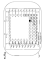
- each PV system 1,1 has eight fields F 1 to F 8 or F 1' to F 8 , whose designation is preceded by the prefix A 1 for system 1 or A 2 for system 2 , In detail, only the first plant A 1 is discussed.
- the first plant A 1 has eight fields A 1 F 1 , A 1 F 2 , ... to A 1 F 8 which in turn are all the same structure.
- each plant field AF has ten electrically parallel strands S, which are numbered S 1 to S 10 .
- Each strand S 1 to S 10 in turn has a series connection of 10 PV modules M, which in turn are numbered M 1 to M 10 .
- a single one of the one hundred PV modules S 1 M 1 to S 10 M 10 is designed fully black, namely the photovoltaic module S 3 M 3 which is assumed to be defective.
- Each module M consists of about 60 PV cells connected in series.
- the PV cell is the smallest unit in which the sun's rays are converted into electricity.
- the 60 cells are connected in series, so that at a working voltage of 1 volt per cell, a voltage of 60 volts builds up across the module.
- the voltage across the entire strand also referred to as strand voltage, is 600 volts.
- the device has two current clamps 5 and 7, which are suitable to one of the two electrical leads 9,9 'of the fields F, one of the two leads 11,11' to the strands S or one of the two leads 13,13 'to a Inverter WR to be installed.
- Such current clamps for the measurement of direct currents are well known.
- the current clamps 5.7 are connected to an evaluation unit 15, which will be discussed later.
- the procedure for identifying the defective strand S 3 will be explained. For reasons of clarity, it is assumed that all PV modules M work the same and perfect otherwise.
- the first current clamp 5 is placed around one of the supply lines 13, 13 'to the first inverter WR 1
- the second current clamp 7 is placed around one of the supply lines 13, 13' of the inverter WR 2 . Since the system A 1 has the defective module, it will generate less power and thus power than the PV system A 2 .
- the working voltage U 1 and U 2 of the two inverters WR 1 and WR 2 must be set to the same voltage value. This is done via an intervention on the MPP controller, as is common in the field of solar technology. By this first step is thus determined that the error that leads to a reduction in performance, must lie in the plant part A 2 .
- both currents measured at the same time are the same, the associated fields A 1 F 1 and A 1 F 2 must also be the same, ie there is normally undisturbed power generation. The case that both fields A 1 F 1 and A 1 F 2 have the same error is very unlikely and is currently being discussed. not considered further.
- one of the current clamps 5, 5 is placed around one of the supply lines 9, 9 'of the second field A 1 F 2 and the other current clamp 7 around one of the supply lines 9, 9' of the third field A 1, F 3 .
- the current clamp 5 .7 which was previously located at the first field A 1 F 1 , is converted to the third field A 1 F 3 .
- the damaged in the third strand S 3 module S 3 M 3 is preferably measured at night, when the PV system is switched off due to the high strand voltage. This takes place, for example, by disconnecting the plug connection between the fifth module S 3 M 5 and the sixth module S 3 M 6 , in order then to check half of the third line S 3 for an interruption. After determining that the interruption must be in the first five modules S 3 M, to S 3 M 5 , the connector between the modules S 3 M 3 and S 3 M 4 can be solved. The subsequent current flow measurement would detect the error in the first part of the modules S 1 M 1 to S 3 M 3 , which would then be examined individually for interruption in the current-carrying path.
- the individual power of each field F 1 to F 8 can be made via a single current measurement.
- the current measurement can be stationary at a fixed to one of the fields F installed power meter or with a mobile device, such as that of the present device.
- This requires that all PV units are connected to the same inverter, which is kept at a constant voltage during all DC measurements, in particular by fixing the MPP (Maximum Power Point) controller of the inverter WR to the constant voltage value.
- MPP Maximum Power Point
- the fields are connected to the same inverter WR 1 , (FIG. or to the adjusted voltage with multiple inverters) and thus at the same voltage.
- the present current is measured at one of the PV units and in a further evaluation unit from the present current value and the ratioed stored measured values the total current or, taking into account the respective operating voltage values of PV units, the total power of the photovoltaic system determined.
- the connecting or supply lines 9,9 ', 11,11'; 13,13 ' can be close to each other or even a greater distance apart.
- no separate bus line is formed in the fields F, but the connecting lines 9, 9 ', 11, 11'; 13,13 'are individually led to the inverter WR and run there, for example, in a cabinet together.
- the associated connection lines can easily be identified by inspection. Particularly in the case of a repeat measurement at a later time, it is necessary to know which of the connection lines 9, 9 ', 11, 11'; 13,13 'the current clamps are to be placed 5.7. Therefore, it makes sense to store an information identifying the location of the measurement together with the current measurement pair or the ratio.
- an RFID chip also fulfills its task, which is fastened to a support of the considered field F and only releases the repeated measurement when the measuring device is at the location predetermined by the RFID chip.
- the distance between the measuring points must be large enough so that the transponder-like working chips can be clearly distinguished.
- a barcode makes sense, which is located on one of the connection lines 9, 9 ', 11, 11'; 13,13 'label is located. The label can be glued directly to the connecting cable.
- the bar code is then registered by means of a suitable reading device and stored with the current value pair or the ratio.
- the measured values of each pair, together with the identification and possibly the present operating voltage, can also be sent wirelessly to a data processing center, where the ratio formation, the performance determination, the determination for defects, etc. are then carried out.
- the current values provided by the measurement data acquisition unit are not directly processed, but a plurality of measurements are made short, i.e., short. within a few seconds or fractions of a second. Subsequently, the arithmetic mean is formed, which can then be used for further processing, such as ratioing.
- the current clamp 5 is placed around the connecting line 9 'of the field A 1 F 2 and the other clamp 7 to the connection line 9 of the field F A 1.
- the current clamps 5,7 are standard current clamps, which are provided with a handle part, to allow easy and quick change.
- the device comprises a selector switch 15, which specifies the measuring range required for the current measurement. This is in the position A for the power of the system, for example, 1000 amps, for the position F for the current of a field, for example, 100 amps and in the position S for the current measurement on a string about 10 amps. Of the current clamps 5,7 lead each two lines 17a, 17b away, leading to the measurement data acquisition unit 3.
- the identification of the measuring location or of the measuring point MS is output to the measuring data acquisition unit 3 by a receiver 19, which records the location data of position registration means.
- a bar code 21 is preferably used with small spacing of the lines 9, 9 'between the fields A 1 F 1 to A 1 F 8 , the receiver 19 then being a bar code reader.
- the bar code 21 can be attached directly to the lines 9,9 '.
- an RFID tag 21a is useful, which is located in the vicinity of the measuring point MS, for example present between the fields A 1 F 2 and A 1 F 3 on the support frame (not shown) of the PV modules M is appropriate.
- the RFID tag 21a has a reception or reaction range of, for example, 2 meters and registers via a transponder function when the measurement data acquisition unit 3 is in its vicinity. Will be served during the stay of Unit 3 within the Communication range of the RFID - 21 a label carried out a measurement, the measured current values of the current pair I 2 and I 3 are forwarded together with the identification of the measuring point MS 2-3 to an evaluation unit 23 or via antenna 25 wirelessly to an external data processing 27.
- GPS positioning can also be carried out together with the measured value acquisition I 2 , I 3 , and the coordinates of the location are combined directly with the current value pair I 2 , I 3 to form a single data record.
- the evaluation unit 23 comprises a ratio former 29 which, from the measured current values I 2 and I 3, forms the ratio, ie I 2 / I 3 , which is applied as an output signal S 1 to the first input of a comparator or a comparison unit 31.
- a reference ratio V ref is set, which has resulted from an arbitrary, earlier measurement than the day of the currently performed measurement, in particular to the day of commissioning. If the current ratio I 2 / I 3 deviates from one another by a predefinable amount, for example 5%, an irregularity in the performance of one of the fields A 1 F 2 or A 1 F 3 may already be inferred here.
- the ratio I 2 / I 3 is greater than 1, the field A 1 F 3 must have a lower current than expected. Conversely, at a ratio I 2 / I 3 less than 1, the field A 1 F 2 results in a lower than expected current.
- a comparison can also be made with the last registered ratio V for this current pair.
- the comparator 31 has a further input to which a signal s 2 is applied, which is read out of a memory element 33 for the ratios V. This comparison allows an assessment of the degradation or of the error occurrence for the last measurement and not with the reference value V ref formed during commissioning, for example, which was stored in a separate memory 35 for the reference values V ref .
- the storage element 33 for the ratios V is also supplied with the signal s 1 from the ratio images 29.
- the storage element 33 for the ratios V is furthermore connected via a signal line s 3 to a linking element 37 which, in an analogous manner as previously combined with the measured current values I 2 , I 3 with the position data of the measuring point in the measured data evaluation unit 3, these positions data also associated with the associated ratios V.
- a linking element 37 which, in an analogous manner as previously combined with the measured current values I 2 , I 3 with the position data of the measuring point in the measured data evaluation unit 3, these positions data also associated with the associated ratios V.
- the logic element 37 are then on a signal line s 4, the ratios V together with the identification of the measuring point MS.
- the linked data pairs of ratio V on the one hand and measuring point MS on the other hand are stored in a separate data storage element 38.
- a stationary current measuring point 41 which permanently or on request measures the measured current, possibly with the associated field voltage.
- the stationary current measuring point 41 can be usefully grown on the field F, which has demonstrated the best performance of all fields after the establishment of the system.
- the steady-state measured current can be used as the reference current I ref equal, at which an assessment of the generated power of all other fields F can be made.
- a further memory element 43 is connected, in which the results of the multiplication for further use, eg for calculating the theoretical power of any fields F, are stored.
- the current I 3 of the field A 1 F3 with the defective module S 3 M 3 can be determined be by the current I 1 of the first field F 1 is multiplied by the two ratios V 1-2 and V 2-3 and, if several inverters WR are present, multiplied by the voltage of the connected inverter WR to determine the power. Due to the defective module M, the ratio VF 2-3 is higher than in the normal case and thus reflects the already known, lower current I 3 again. In this way, all fields F which have previously been encountered can be examined and the sum of the lower power of all defective fields F can be calculated with only one current measurement per system A.
- the ratio V to the leading and trailing strand S or field F would be defined as infinity and zero, respectively.
- any ratio of zero or infinity is masked out and, consequently, a ratio V is formed from the directly preceding and following strand S or field F.
- the current values I 2 and I 3 can also be applied directly to a comparison part 45, which directly compares the currents I 2 , I 3 with reference currents that correspond to measured and saved at an earlier point in time.
- the current pair value I 2 , I 3 are applied to the input of a power comparator 47, the other input for the value of the voltage U 1 at the inverter WR 1 , or in the presence of several inverters also correspondingly many inputs for the operating voltage value U of the respective WR.
- an input is provided at the power comparator 47, at which a signal s 5 , which reflects the reference power P ref either of the reference PV unit, ie present the reference field F 4 , or the power of previous measurements, applied as a comparison reference signal.
- the power comparator 47 has an output 49 in which a warning signal can be tapped in the case of an impermissibly high deviation from the comparison reference value or from the power value with one another.
- FIG. 2 is still shown a computing unit 49 which is connected to the evaluation unit 3 and from this with the multiplied current values I 1 , (I 1 * V 1-2 ), (I 1 * V 2-3 ), (I 1 * V 3 -4 ), .... (I 1 * V 7-8 ) is supplied (* corresponds to a multiplication).
- the currents of all fields F are added and given as a value of the total current I tot of the system A 1 to another multiplier 51, in which still the voltage value U of the reference field, in the example of the field F 4 , is entered.
- the output signal s 6 of the further multiplier 51 is the theoretically present power P theoretical , which is displayed on a display 53.
- the real instantaneous power P real determined via the actual current measured at the inverter WR can be displayed on the display 53, so that a continuous visual comparison of the present power P with the theoretically expected power is possible.
- the housing of the device 1 which has an integrated direct current source 55 inside, which feeds a line 59 with a calibration current I calibrated via a measuring shunt 57.
- the conduit 59 extends partially through the interior of a bracket 61 which is integrally formed on the housing.
- the bracket 61 and the line 59 are dimensioned so that they can be enclosed by the two current clamps 5.7 simultaneously.
- a switch 63 closes the calibration circuit.
- the switch 63 is preferably provided as a push button or lever on the housing surface.
- the above-described calibration via the measuring shunt 57 serves to specify the absolute measured value and is therefore preferable to the calibration with one another.
Abstract
Description
Die Erfindung bezieht sich auf ein Verfahren zum Auffinden eines defekten PV-Moduls innerhalb einer größeren PV-Anlage und auf eine zugeordnete Vorrichtung.The invention relates to a method for finding a defective PV module within a larger PV system and to an associated device.
Große PV-Anlagen können Tausende von PV-Modulen umfassen, die einzeln ausge-messen werden müssen, um ein schadhaftes Modul zu erkennen und zu lokalisieren. Dieser Aufwand ist notwendig, da das Vorhandensein eines einzigen oder auch mehrerer defekter Module bei der Gesamtleistung nicht weiter auffällt. Ein defektes Modul, bei dem eine Photovoltaikzelle nichtleitend ist oder bei dem die Lötverbindung zwischen zwei Zellen unterbrochen ist, führt zu einem Ausfall des gesamten Stranges von z.B. zehn in Serie geschalteten PV-Modulen, da eine einzige Unterbrechung auch die Serienverbindung unterbricht. Bei einer Leistung von 2 MW entspricht der Beitrag eines Strangs von z.B. 2 KW einem Tausendstel der Leistung. Selbst mehrere über die Zeit defekte Stränge fallen nicht sofort auf, da die Abweichung in der generierten Leistung auch Wetter bedingt sein kann. Permanent installierte Systeme zur Leistungsmessung sind mit einem nicht vertretbaren Kostenaufwand verbunden.Large PV systems can include thousands of PV modules that need to be individually measured to detect and locate a faulty module. This effort is necessary because the presence of a single or even more defective modules in the overall performance is not noticeable. A defective module in which a photovoltaic cell is nonconductive or in which the solder joint between two cells is broken leads to failure of the entire strand of e.g. ten PV modules connected in series, as a single interruption also interrupts the serial connection. For a power of 2 MW, the contribution of one strand of e.g. 2 KW one thousandth of the power. Even multiple strands that are defective over time are not immediately noticeable, as the deviation in the generated power can also be weather-related. Permanently installed systems for power measurement are associated with an unreasonable cost.
Neben obigem Problem der nicht entdeckten Minderleistungsfähigkeit der PV-Anlage ist es insbesondere im Garantiezeitraum wichtig, dass gerechtfertigte Reklamations-möglichkeiten erkannt werden, um den Hersteller des defekten PV-Moduls in die Pflicht zu nehmen.In addition to the above problem of undetected underperformance of the PV system, it is important, in particular during the guarantee period, that justified complaints are identified in order to oblige the manufacturer of the defective PV module.
Mit dem heutigen Stand der Technik sind verschiedene Möglichkeiten der Überprüfung der Leistungsfähigkeit von PV-Modulen bekannt. Bei allen Verfahren, welche ein aussagekräftiges Ergebnis liefern, muss die PV-Anlage vom Wechselrichter entkoppelt und an ein Messgerät angeschlossen werden.With the current state of the art, various possibilities of checking the performance of PV modules are known. For all processes that provide a meaningful result, the PV system must be decoupled from the inverter and connected to a measuring device.
Als Messgerät kommen hierbei Multimeter zum Einsatz, in dem diese den Kurzschlussstrom und die Leerlaufspannung eines PV-Moduls, Stranges oder einer PV-Einheit bestimmen. Ziel dieser Messung ist, die grundsätzliche Funktion des PV-Moduls, Stranges bzw. der PV-Einheit zu erkennen.In this case, multimeters are used as measuring devices, in which they measure the short-circuit current and the open-circuit voltage of a PV module, strand or determine a PV unit. The aim of this measurement is to recognize the basic function of the PV module, strand or the PV unit.
Soll die Leistungsfähigkeit eines PV-Moduls, Stranges oder einer PV-Einheit ermittelt werden, so geschieht dies vorzugsweise durch das Anschließen eines U-I-Kennlinienmessgerätes, welches die entsprechende U-I-Kennlinie messen kann. Die so gemessene Kennlinie wird ergänzt um den Messwert eines Einstrahlungssensors bzw. einer Referenzsolarzelle sowie des Messwertes eines Temperaturfühlers, welcher die Temperatur des PV-Moduls misst. Der STC-Leistungswert (Standardisierter Leistungswert für Photovoltaikmodule) errechnet sich aus den oben genannten Werten -Einstrahlung, Temperatur, Spannung und Strom - zusammen. Dieser hat jedoch aufgrund der vielen Toleranzen bei den Sensoren, welche zur Berechnung herangezogen werden, eine hohe Ungenauigkeit.If the performance of a PV module, line or a PV unit is to be determined, this is preferably done by connecting a U-I characteristic measuring device, which can measure the corresponding U-I characteristic. The characteristic thus measured is supplemented by the measured value of an irradiation sensor or a reference solar cell as well as the measured value of a temperature sensor, which measures the temperature of the PV module. The STC power value (standardized power value for photovoltaic modules) is calculated from the above values - radiation, temperature, voltage and current - together. However, this has a high degree of inaccuracy due to the many tolerances in the sensors, which are used for the calculation.
Weiterhin ist aus dem Stand der Technik das Messen mit einer Stromzange bekannt, da man mit dieser im laufenden Betrieb die Stromstärke eines PV-Moduls, Stranges oder einer PV-Einheit ermitteln kann. Da jedoch Spannung, Einstrahlung und Temperatur unbekannt sind, genügt diese Art der Messung lediglich der reinen Überprüfung der Funktionalität sowie der Überprüfung von Sicherungen. Alle zum Stand der Technik gehörenden Verfahren und Vorrichtungen haben hinsichtlich Genauigkeit, Zeitaufwand und Anwendbarkeit während des Betriebes keine ausreichend präzise Aussagekraft.Furthermore, the measurement with a current clamp is known from the prior art, since it can determine the current of a PV module, strand or a PV unit with this during operation. However, since voltage, irradiation and temperature are unknown, this type of measurement is sufficient merely to check the functionality and check fuses. All of the prior art methods and devices have in terms of accuracy, time and applicability during operation is not sufficiently accurate information.
So liegt vorliegender Erfindung die Aufgabe zugrunde, einen defekten Strang, in welchem ein defektes PV-Modul sein muss, mit wenig technischem und zeitlichem Aufwand zu erkennen.Thus, the present invention is the object of a defective strand, in which a defective PV module must be to recognize with little technical and time.
Diese Aufgabe wird bezüglich des Verfahrens durch eine zeitgleiche Messung der Ströme zweier PV-Einheiten mittels zweier Stromzangen und einer Messdaten-erfassungseinheit, welche die Messwerte für eine Ermittelung der Leistungsfähigkeit der betreffenden PV-Einheiten einer Auswerteeinheit bereitgestellt, gelöst. Dabei können folgende Unterscheidungen getroffen werden: a) bei baugleichen PV-Einheiten, die auf derselben Betriebsspannung arbeiten, wird die PV-Einheit mit geringerem Strom als die PV-Einheit geringerer Leistung ermittelt, b) bei baugleichen PV-Einheiten, die auf unterschiedlicher Betriebsspannung arbeiten, wird die PV-Einheit mit geringerem Produkt von gemessenem Strom und ermittelter Betriebs-spannung bei der dem jeweiligen Stromwert zugeordneten PV-Einheit als die PV-Einheit geringerer Leistung ermittelt, c) bei nicht-baugleichen PV-Einheiten, die auf derselben Betriebsspannung arbeiten, wird die PV-Einheit mit geringerem Strom als die PV-Einheit geringerer Leistung ermittelt, und d) bei nicht-baugleichen PV-Einheiten, die auf unterschiedlicher Betriebsspannung arbeiten, wird die PV-Einheit mit geringerem Produkt von gemessenem Strom und ermittelter Betriebsspannung bei der dem jeweiligen Stromwert zugeordneten PV-Einheit als die PV-Einheit geringerer Leistung ermittelt.This object is achieved with respect to the method by a simultaneous measurement of the currents of two PV units by means of two current clamps and a measurement data acquisition unit, which provided the measured values for determining the performance of the respective PV units of an evaluation unit. The following distinctions can be made: a) for identical PV units that are at the same operating voltage b) For identical PV units operating at different operating voltages, the PV unit will provide a lower product of measured current and operating voltage c) for non-identical PV units operating at the same operating voltage, the PV unit is determined to be lower in power than the lower-performance PV unit, c) the PV unit assigned to the respective current value is determined to be the lower-power PV unit; and d) for non-identical PV units operating at different operating voltages, the PV unit with lower product of measured current and determined operating voltage is determined to be the lower power PV unit at the PV unit associated with the respective current value.
Bei der vorliegend verwendeten Terminologie wird unter einer PV-Einheit dabei sowohl ein einzelnes Modul, als auch ein einzelner Strang, als auch ein aus mehreren parallelen Strängen aufgebautes PV-Feld angesehen. Bei den zur Zeit in der Diskussion stehenden Großanlagen von 100 MW oder mehr können auch komplette PV-Anlagen als PV-Einheit im vorliegenden Sinne verstanden werde, wenn mehrere dieser PV-Anlagen ein räumlich zusammenhängendes Gesamtsystem bilden.As used herein, a PV unit means both a single module, as well as a single strand, as well as a PV array composed of multiple parallel strands. In the large-scale plants currently under discussion of 100 MW or more, it is also possible to understand complete PV systems as a PV unit in the present sense if several of these PV systems form a spatially coherent overall system.
In einer praktischen Vorgehensweise werden zuerst die Ströme von zwei PV-Feldern miteinander verglichen. Dabei spielt es keine Rolle welche der beiden vorhandenen Anschlussleitungen für den Messvorgang herangezogen wird. Wichtig ist es, dass die Messung zeitgleich erfolgt, damit zum Messzeitpunkt dieselben Rahmenbedingungen vorliegen. Dieses sind im Wesentlichen die Temperatur der PV-Zellen und die zwischen den Anschlussleitungen anliegende Spannung. Wenn alles in Ordnung ist, müssten zwei gleich aufgebaute PV-Felder, die auf derselben Spannung arbeiten, auch denselben Gleichstrom erzeugen, es sei denn, dass einer der Stränge eines der Felder defekt ist. Ist einer der gemessenen Ströme ungewöhnlich geringer, z.B. eine Verminderung um mehr als 5%, als der andere zeitgleich gemessene Strom, so wird als nächster Schritt weiter in die Tiefe gemessen, indem die Ströme zweier Stränge des defekt vermuteten PV-Feldes analog wie zuvor gemessen und miteinander verglichen werden. Liegt die Abweichung beider Ströme im Toleranzbereich von z.B. den genannten 5%, so sind beide Stränge in Ordnung und die Messung wird an zwei anderen Strängen desselben Feldes wiederholt. So wird Strang um Strang miteinander verglichen, bis der Strang identifiziert ist, der unterbrochen ist, oder einen nicht tolerierbaren Minderstrom führt. Das defekte Modul im Strang kann dann mit wenig weiterem Aufwand bestimmt werden.In a practical procedure, first the currents of two PV arrays are compared. It does not matter which of the two existing connecting cables is used for the measuring process. It is important that the measurement takes place at the same time so that the same conditions exist at the time of measurement. This is essentially the temperature of the PV cells and the voltage applied between the leads. If all is well, two equally constructed PV arrays operating at the same voltage would also have to produce the same DC current, unless one of the strings of one of the arrays is defective. If one of the measured currents is unusually lower, for example a reduction of more than 5%, than the other current measured at the same time, then the next step is to measure the depth by measuring the currents of two strings of the defectively suspected PV field analogously as before and compared with each other. If the deviation of both currents lies in the tolerance range of, for example, the stated 5%, then both strands are in order and the measurement is repeated on two other strands of the same field. Thus, string by string is compared until the strand is identified that is broken or has an intolerable underflow. The defective module in the strand can then be determined with little further effort.
Bei nicht baugleichen PV-Einheiten wird zunächst eine zeitgleiche Messung (zum Teil auch Feststellung genannt) der Ströme durch je eine Anschlussleitung der beiden PV-Einheiten vorgenommen. Dann wird in einem entsprechenden Bauteil das Verhältnis der beiden Ströme zueinander gebildet. Schließlich wird durch Vergleich des Verhältnisses mit einem Vergleichsverhältnis, welches aus Messwerten der Gleichströme durch die je eine Anschlussleitung der beiden PV-Einheiten zu einem früheren Zeitpunkt als dem Zeitpunkt der aktuellen Messung oder Feststellung gebildet wurde, ermittelt, ob eine Veränderung der Leistungsfähigkeit in einer der PV-Einheiten eingetreten ist.For non-identical PV units, a simultaneous measurement (sometimes called a determination) of the currents is carried out by one connection lead of each of the two PV units. Then, the ratio of the two currents is formed in a corresponding component to each other. Finally, by comparing the ratio with a comparison ratio, which was formed from measured values of the direct currents through which each one connecting line of the two PV units was earlier than the time of the current measurement or determination, it is determined whether a change in performance in one of PV units has occurred.
Bei einer Anlage mit nicht-baugleichen PV-Einheiten liegt die Schwierigkeit vor, dass die PV-Felder z.B. zehn oder nur acht Stränge aufweisen oder auch die Stränge unterschiedliche Anzahlen an PV-Modulen besitzen. Theoretisch könnte auch das erste Verfahren Anwendung finden, wenn eine Tabelle mit Korrekturfaktoren erstellt wird, die der Unterschiedlichkeit Rechnung trägt und bei den vergleichenden, zeitgleichen Strommessungen die einzelnen Strommessungen entsprechend gewichtet werden.In a plant with non-identical PV units, there is the difficulty that the PV fields, e.g. have ten or only eight strands or even the strands have different numbers of PV modules. Theoretically, the first method could also be applied if a table with correction factors is created which takes into account the differences and the individual current measurements are weighted accordingly in the comparative, simultaneous current measurements.
Einfacher ist die oben genannte vorteilhafte Ausführungsform, bei der ohne Kenntnis der Unterschiede die Ströme zweier PV-Felder zeitgleich gemessen und zueinander ins Verhältnis gesetzt werden. Dieses kann zweckmäßigerweise in zeitlicher Nähe zur Errichtung der PV-Anlage geschehen, wenn davon auszugehen ist, dass die gelieferten und getesteten PV-Module bei der Inbetriebnahme der PV-Anlage in Ordnung sind. Dann liegt ein Verhältnis der Performance der beiden PV-Einheiten vor, bei dem andere Parameter wie die aktuelle Sonneneinstrahlung, die herrschende Temperatur etc. ausgeklammert sind, da sie für beide PV-Einheiten gleichermaßen gelten. Zu einem späteren Zeitpunkt, zum Beispiel einige Monate vor Ablauf der Garantiefrist oder bei einer mangelnden Leistung der Anlage wird die Strommessung an den PV-Einheiten wiederholt. Wenn das Verhältnis noch gleich ist, kann mit einiger Wahrscheinlichkeit auf den korrekten Zustand der PV-Einheiten geschlossen werden, da ein gleich wirkender Mangel bei beiden PV-Einheiten eher unwahrscheinlich ist. Ist das Verhältnis hingegen abweichend, so muss in Abhängig der Richtung der Änderung die eine oder das andere verglichene PV-Einheit mangelhaft sein.The above-mentioned advantageous embodiment is simpler, in which, without knowing the differences, the currents of two PV fields are measured at the same time and set in relation to one another. This can conveniently take place in temporal proximity to the construction of the PV system, if it can be assumed that the delivered and tested PV modules are in order during commissioning of the PV system in order. Then there is a ratio of the performance of the two PV units, with the others Parameters such as the current solar radiation, the prevailing temperature, etc. are excluded, since they apply equally to both PV units. At a later date, for example a few months before the expiry of the guarantee period or in the event of a lack of performance of the installation, the current measurement on the PV units will be repeated. If the ratio is still the same, it can be concluded with some probability on the correct state of the PV units, since a similar defect in both PV units is unlikely. If the ratio is different, however, depending on the direction of the change, one or the other compared PV unit must be deficient.
In diesem Zusammenhang ist es sinnvoll, wenn bei einer PV-Anlage die aus mindestens drei PV-Einheiten besteht, folgende Schritte ablaufen: i) bei allen vorhandenen PV-Einheiten wird zeitgleich an jeweils zwei, ein Paar bildende PV-Einheiten eine Strommessung vorgenommen, bis der Strom jeder PV-Einheit zumindest einmal gemessen wurde; ii) die beiden zu jedem Paar gemessenen Stromwerte werden zueinander ins Verhältnis gesetzt; und iii) die Verhältnisse werden in einem elektronischen Speicherelement abgelegt. Bei dieser Vorgehens-weise ist es wiederum von besonderem Vorteil, wenn die Paarbildung bei der Strommessung nach Schritt i) an benachbarten PV-Einheiten vorgenommen wird, wobei die Paare von benachbarten PV-Einheiten so gewählt werden, dass zumindest teilweise eine zusammenhängende Kette von Paaren als Glieder gebildet wird. Der Vorteil (auch ohne Paarbildung) wird anhand eines Beispiels deutlich:In this context, it makes sense for a PV system consisting of at least three PV units to take the following steps: i) in the case of all existing PV units, current measurements are carried out simultaneously on two pairs of PV units each, until the current of each PV unit has been measured at least once; ii) the two current values measured for each pair are set in relation to each other; and iii) the ratios are stored in an electronic memory element. In this procedure, it is again particularly advantageous if the pairing in the current measurement after step i) is carried out on adjacent PV units, wherein the pairs of adjacent PV units are selected so that at least partially a contiguous chain of pairs is formed as limbs. The advantage (even without pairing) becomes clear with an example:
Es wird bei einer PV-Anlage mit n=100 Feldern zu je 10 Strängen mit je acht PV-Modulen bei den Feldern 1 und 2, die dann als PV-Einheit im Sinne der Ansprüche anzusehen sind, mit der Vergleichsmessung begonnen, wobei sich ein Verhältnis von 1:1 = 1 ergibt, also identische Stromwerte. Bei der nächsten Messung werden die Felder 2 und 3 miteinander verglichen, wobei sich ein Verhältnis von 1:1,1 = 1,1 ergibt. Bei der folgenden Messung mit den PV-Feldern 3 und 4 liegt ein Verhältnis von 1:0,98 = 0,98 vor usw. Es werden 99 dieser fortschreitenden Messung durchgeführt, bis zur letzten Messung zwischen den PV-Einheiten oder Feldern n-1 und n. Dadurch lässt sich ein Zusammenhang zwischen allen Feldern berechnen, der z.B. beim ersten Feld zum letzten Feld der Multiplikation aller 99 Verhältnisse oder Faktoren ist. Zwischen dem ersten Feld und dem vierten Feld ist der Zusammenhang 1 mal 1,1 mal 0,98 = 1,078. Wird nun zu einem späteren Zeitpunkt an einer der PV-Einheiten der absolut vorliegende Strom gemessen, so kann in einer Recheneinheit aus dem absoluten Stromwert und den ins Verhältnis gesetzten abgespeicherten Messwerten der Gesamtstrom oder die Gesamtleistung der Photovoltaikanlage bestimmt werden, wie sie vorherrschen würde, wenn keine Störung, Degradation oder Defekte vorlägen. Ist der theoretisch ermittelte Gesamtwert der PV-Anlage deutlich höher als der momentan zum Zeitpunkt der Einzelmessung an einer der PV-Einheiten vorgelegene Einspeisewert, so können Rückschlüsse auf einen Fehler gezogen werden. Bei einer Einspeisung über mehrere Wechselrichter sollten die PV-Einheiten während der zeitgleichen Messung auf den gleichen Spannungswert gesetzt werden, der dann auch bei der späteren Strommessung zur Ermittlung der Gesamtleistung der PV-Anlage einzustellen ist.For a PV system with n = 100 fields of 10 strings each with eight PV modules in the
Vorteilhaft ist die angesprochene Gliederbildung der Paare. Wenn von einem "Strompaar" die Rede ist, wird darunter immer das Wertepaar der beiden zeitgleich gemessenen Ströme verstanden. Der Vorteil liegt in der vereinfachten Zuordnung der Messstelle zu den gemessenen Stromwerten. Prinzipiell kann in der Anlage jedes beliebige Feld mit jedem anderen Feld zu einem Paar kombiniert werden. Dann muss aber für die spätere Messung die gleiche Zuordnung vorliegen, da die gebildeten Verhältnisse untereinander nur für dieses eine Paar gelten. Diese identische Zuordnung ist schwieriger vorzunehmen bei beliebig gewählten Paaren als bei Paaren von benachbarten PV-Einheiten. Die Zuordnung spielt für den Monteur eine Rolle, der mit der Messvorrichtung an die zu Messenden Felder gehen muss. Liegen diese weit auseinander, muss er mit Verlängerungsleitungen arbeiten, die Hunderte von Metern lang sein und damit auch das Ergebnis verfälschen können. Ein Messung bei benachbarten PV-Feldern kann dagegen mit einer Zuleitung zu den Messmitteln, in der Regel Stromzangen, von wenigen Metern erfolgen. Die Bildung der Verhältnisse unter benachbarten Paaren hat noch den Vorteil, dass die PV-Zellen - Temperatur bei benachbarten PV-Einheiten zumindest ähnlich ist. Eine Wolke wird sich nicht, eine längere Auskühlungszeit bewirkend, scharfkantig an eine geometrische Trennlinie der PV-Einheiten am Boden halten, sondern die benachbarten Felder eher gleichmäßig abschatten.Advantageous is the mentioned articulation of the pairs. When talking about a "current pair", this always means the value pair of the two simultaneously measured currents. The advantage lies in the simplified assignment of the measuring point to the measured current values. In principle, any field in the plant can be combined with any other field to form a pair. Then, however, the same assignment must be present for the subsequent measurement, since the relationships formed with one another only apply to this one pair. This identical assignment is more difficult to do with arbitrarily selected pairs than with pairs of adjacent PV units. The assignment plays a role for the fitter, who has to go with the measuring device to the measuring fields. If these are far apart, he has to work with extension cables that can be hundreds of meters long and thus falsify the result. On the other hand, a measurement on adjacent PV fields can be made with a supply line to the measuring devices, usually current clamps, of a few meters. The formation of the relationships among adjacent pairs still has the advantage that the PV cell temperature is at least similar for adjacent PV units is. A cloud will not, keeping a longer cooling time, sharp-edged hold on a geometric dividing line of the PV units on the ground, but shade the adjacent fields rather evenly.
In diesem Zusammenhang ist auch eine Querkontrolle sinnvoll, bei der nach einer vorgegebenen Anzahl, z.B. nach zehn, in einer bestimmten Reihenfolge gemes-senen Stromwertepaaren eine Quermessung vorgenommen wird, bei der zeitgleich der Stromwert der vormals ersten gemessenen PV-Einheit und der der letzten gemessenen PV-Einheit ermittelt, zueinander ins Verhältnis gesetzt und mit dem Produkt der zehn Einzelverhältnisse verglichen werden. Wurde z.B. anhand der zehn Einzelmessungen an den zehn PV-Einheiten-Paaren eine Reihe von zehn Verhältnissen errechnet, dass insgesamt 1:1,1 (entsprechend dem Produkt der zehn Einzelverhältnisse) ergibt, so müsste bei einwandfreier Kalibrierung der Stromzangen auch das Querverhältnis des Stroms der ersten PV-Einheit zum Strom der zuletzt gemessenen PV-Einheit 1:1,1 betragen. Ist dieses nicht der Fall, indem sich z.B. ein Verhältnis von 1:1,15 ergibt, so kann auf eine nicht optimale Kalibrierung geschlos-sen werden und die zehn errechneten Einzel-Verhältnisse können korrigiert werden, in dem die Differenz, e.g. 0,05, auf alle zehn Verhältnisse gleichmäßig aufgeteilt wird. Dies entspricht eine Erhöhung um 0,005 bei jedem der zu den zehn PV-Einheiten-Paaren errechneten Verhältnisse.In this context, a lateral control makes sense, in which after a predetermined number, e.g. After ten measured in a certain order current value pairs a transverse measurement is made, at the same time determines the current value of the formerly first measured PV unit and the last measured PV unit, set in relation to each other and compared with the product of the ten individual ratios become. Was e.g. Based on the ten individual measurements on the ten PV unit pairs calculated a number of ten ratios that total 1: 1,1 (corresponding to the product of the ten individual ratios), so with proper calibration of the current clamps and the transverse ratio of the current of the first PV unit to the current of the last measured PV unit 1: 1.1 amount. If this is not the case, e.g. gives a ratio of 1: 1.15, it can be concluded that the calibration is not optimal, and the ten calculated individual ratios can be corrected, in which the difference, e.g. 0.05, evenly distributed over all ten ratios. This corresponds to an increase of 0.005 for each of the ratios calculated for the ten PV unit pairs.
Eine Erleichterung für das die Messungen vornehmende Personal ist es auch, wenn bei jeder Messung nach Schritt i) eine Identifikation der Messstelle, insbesondere der Ort der Messung, registriert wird und zusammen mit dem an dem Ort gemessenen Wert des Strompaares oder des daraus errechneten Verhältnisses abgespeichert wird. Der Ort der Messung kann dabei mittels GPS, eines RFID Chip oder mittels eines Barcodelesers zum Zeitpunkt der Stromerfassung mit aufgenommen werden. Der Chip oder die RFID - Etikette ist an einer Stelle des Traggerüsts für die PV-Anlage dauerhaft angebracht. Sind die PV-Einheiten bei der Paarbildung zueinander benachbart, braucht der Monteur lediglich von Messstelle zu Messstelle zu gehen, die Stromzangen um je eine Zuleitung legen, den Messvorgang starten und nach der Messung zur nächsten Messstelle wandern. Dieser Vorgang kann bei der erstmaligen Aufnahme der Gegebenheiten, i.e. der Verhältnisbildung, so weit protokolliert werden, dass der Monteur bei der wiederholten Messung oder Überprüfung lediglich zum Anfang der Kette geht und dort beginnt. Nach erfolgter Messung und ggf. Verhältnisbildung wird ihm dies durch eine LED am Messgerät signalisiert und er geht zur nächsten Messstelle. Die Messung wird erst freigegeben, wenn eine weitere, andersfarbige LED ihm dies signalisiert. Die Signalisierung erfolgt, wenn entweder das korrekte GPS Signal mit "Ziel erreicht" übertragen wird, die Transponderreaktion mit der RFID-Etikette positiv ist, der korrekte, zuvor abgespeicherte Barcode eingelesen wurde oder dergleichen. Erst dann weiß der Monteur, dass er an der vorgesehenen nächsten Messstelle ist und die ermittelten Werte auch die beabsichtigten sind.It is also a relief for the personnel carrying out the measurements if, for each measurement after step i), an identification of the measuring point, in particular the location of the measurement, is registered and stored together with the value of the current pair or the ratio calculated therefrom becomes. The location of the measurement can be recorded by means of GPS, an RFID chip or by means of a barcode reader at the time of current detection. The chip or the RFID tag is permanently attached to a location of the support structure for the PV system. If the PV units are adjacent to each other during pairing, the installer only needs to go from measuring point to measuring point, place the current clamps around one supply line each, start the measuring process and move to the next measuring point after the measurement. This process may be the first time Recording the conditions, ie the ratio formation, are logged so far that the fitter only goes to the beginning of the chain during the repeated measurement or inspection and begins there. After the measurement and, if necessary, ratio formation, this is signaled to him by an LED on the measuring device and he goes to the next measuring point. The measurement is only released when another, differently colored LED signals this. The signaling takes place when either the correct GPS signal with "target reached" is transmitted, the transponder reaction with the RFID tag is positive, the correct, previously stored barcode has been read or the like. Only then does the installer know that he is at the intended next measuring point and the values determined are also the intended ones.
Bei weniger gut ausgebildeten Kräften ist es auch denkbar auf jedwede Reihenfolge bei der Messwertaufnahme zu verzichten und sich nur auf die korrekt erfolgte Korrelation von Messort und Messwert zu verlassen. Die Recheneinheit kann dann das Vorliegen aller erforderlichen, das heißt zu jedem Paar mindestens einer, Messwerte feststellen und ggf. in eine vorgegebene Reihenfolge sortieren. Die Vorgehensweise von benachbarten zu benachbarten PV-Einheiten zu wechseln, ist insbesondere bei fehlender Positionsfeststellung vorzunehmen.With less well-trained forces, it is also conceivable to dispense with any sequence in the measured value recording and to rely only on the correct correlation of location and measured value. The arithmetic unit can then determine the presence of all required, that is, for each pair at least one, measured values and, if necessary, sort in a predetermined order. The procedure of changing from adjacent to adjacent PV units is to be carried out in particular in the absence of position determination.
Die Bildung der Verhältnisse zwischen den beiden zeitgleich gemessenen Gleichstromwerten zueinander kann direkt vor Ort erfolgen, oder aber die Messwerte jeden Paares werden zusammen mit der Identifikation drahtlos an eine Datenver-arbeitungsstelle gesendet, wo sie abgespeichert und weiterverarbeitet werden.The relationships between the two simultaneously measured direct current values can be formed directly on site, or the measured values of each pair can be transmitted wirelessly together with the identification to a data processing point where they are stored and further processed.
Zur Erzielung einer hohen Zuverlässigkeit der abgespeicherten Verhältnisse es sinnvoll, die Strommessung kurz (z.B. einige Millisekunden) hintereinander mehrere Male, z.B. fünf bis zehn Mal, vorzunehmen und das arithmetische Mittel über die kurz hintereinander vorgenommenen Strommessungen zu bilden. Das Verhältnis wird dann aus den arithmetischen Mitteln der Stromwerte gebildet und ist damit auf eine solidere Basis gestellt. Zusammen mit den Messwerten des Gleichstroms oder der Verhältnisse kann auch der, z.B. am Wechselrichter gemessene, Spannungswert zwischen den beiden Anschlussleitungen der PV-Einheit abgespeichert werden.To achieve a high reliability of the stored conditions, it makes sense to make the current measurement briefly (eg a few milliseconds) in succession several times, for example five to ten times, and to form the arithmetic mean over the short-term current measurements. The ratio is then formed from the arithmetic mean of the current values and is thus placed on a sounder basis. Together with the measured values of the direct current or the ratios can also, for example, on Inverter measured, voltage value between the two connecting lines of the PV unit are stored.
Da jede Messung über die spätere Multiplikation der Verhältnisse auch einen Beitrag zur Messungenauigkeit liefert, ist es zur Sicherstellung einer tolerablen Messab-weichung vorgesehen, nach jeder dritten bis zwanzigsten Messung, vorzugsweise nach jeder fünften bis zehnten Messung, eine Kalibrierung der Messvorrichtung vorzunehmen.Since each measurement on the subsequent multiplication of the ratios also provides a contribution to the measurement inaccuracy, it is provided to ensure a tolerable Messab- deviation, make every three to twentieth measurement, preferably after every fifth to tenth measurement, a calibration of the measuring device.
Das vorgestellte Verfahren ist nicht zur täglichen Anwendung vorgesehen, sondern eher zur Überprüfung der Leistungsfähigkeit der PV-Anlage in regelmäßigen Zeitabständen von z.B. einigen Monaten. Insofern ist es vertretbar, dass alle PV-Einheiten, die auf denselben Wechselrichter geschaltet sind, während aller Gleichstrommessungen auf eine konstante Spannung gehalten werden, indem der MPP (Maximal Power Point) - Regler des Wechselrichters auf den konstanten Spannungswert fixiert wird.The presented method is not intended for daily use, but rather for checking the performance of the PV system at regular intervals of e.g. few months. Thus, it is reasonable for all PV units connected to the same inverter to be held at a constant voltage during all DC measurements by fixing the MPP (Maximum Power Point) controller of the inverter to the constant voltage value.
Zur Beurteilung, inwieweit eine einzelne PV-Einheit gegebenenfalls von ihrer zu erwartenden Leistung abweicht, ist es zweckmäßiger Weise vorgesehen, dass eine einzige der PV-Einheiten mittels Strommessung, Spannungsmessung, Einstrahlungs-intensität und direkter oder indirekter Temperaturmessung am Halbleiter als Referenz-PV-Einheit nach dem für Photovoltaikmodule zur Ermittlung der Norm-leistung festgelegten, standardisierten Testbedingungen (STC) ermittelt wird, um dann die Normleistung (nach STC) einer, mittels der Stromwertpaare verketteten PV-Einheit zu errechnen.In order to assess the extent to which an individual PV unit may deviate from its expected power, it is expedient for a single one of the PV units to be used as the reference PV device by means of current measurement, voltage measurement, irradiation intensity and direct or indirect temperature measurement. Unit is determined according to the standardized test conditions (STC) specified for photovoltaic modules for determining the standard power, and then to calculate the standard power (according to STC) of a PV unit linked by means of the current value pairs.
Insbesondere bei gleich aufgebauten PV-Einheiten kann eine solche Abschätzung zur individuellen Performance einer PV-Einheit auch durch Vergleich mit einer Referenz-PV-Einheit erfolgen, die zuvor als solche definiert wurde. Dies ist vorteilhafterweise diejenige PV-Einheit, die bei der erstmaligen Leistungsermittlung an einem Wetter bezogenen Idealtag, z.B. anlässlich der Inbetriebnahme der Photovoltaikanlage, die höchste Leistung erzeugt hat. Diese Leistung wird dann als bestmögliche Referenz für den verbauten Typ an PV-Einheit herangezogen. Weicht die Leistung einer anderen, beliebigen PV-Einheit von einem Grenzwert von z.B. 95% der Referenzeinheitsleistung nach unten ab, wird auf eine schadhafte Montage oder ein defektes Bauteil geschlossen.In particular, in the case of identically constructed PV units, such an estimate for the individual performance of a PV unit can also be made by comparison with a reference PV unit that was previously defined as such. This is advantageously that PV unit which has generated the highest power during the first performance determination on a weather-related ideal day, eg on the occasion of the commissioning of the photovoltaic system. This power is then used as the best possible reference for the installed type of PV unit. Dodges the power of another, any PV unit from a limit of, for example, 95% of the reference unit power downwards, it is concluded that there is a faulty mounting or a defective component.
Bezüglich der Vorrichtung wird die eingangs vorgebrachte Aufgabe durch ein Strommessgerät mit zwei Stromzangen zur zeitgleichen Messung eines Gleichstroms, mit einem Positionsregistriermittel zur Erfassung der Position des Messgerätes zum Zeitpunkt der Messung und mit einer Antenne zum Übermitteln der Mess- und Positionsdaten und/oder mit einem Datenspeicher zum Einschreiben der Mess- und Positionsdaten, gelöst. Die Stromzangen werden um jeweils eine der zu einer PV-Einheit gehörigen zwei Anschluss- oder Zuleitungen gelegt. Da solche Stromzangen zur Gleichstrommessung mit Magnetfeldern arbeiten, ist eine regelmäßige Kalibrierung erforderlich, was durch eine integrierte Gleichstromquelle, die einen Messshunt speist, erfolgt. Die Stromzangen werden um einen elektrischen Leiter, vorzugsweise einen Bügel, durch welchen ein von der Gleichspannungsquelle generierter Kalibrierstrom fließt, gelegt. Der Leiter ist zur gleichzeitigen Aufnahme beider Stromzangen ausgelegt, so dass auch der Kalibriervorgang für beide Stromzangen identisch abläuft.With regard to the device, the object presented at the outset is provided by a current measuring device with two current clamps for the simultaneous measurement of a direct current, with a position registering means for detecting the position of the measuring device at the time of measurement and with an antenna for transmitting the measurement and position data and / or with a data memory for writing the measurement and position data, solved. The current clamps are placed around one of the two connection or supply lines belonging to one PV unit. Since such current clamps for DC measurement work with magnetic fields, a regular calibration is required, which is done by an integrated DC power source that feeds a shunt. The current clamps are placed around an electrical conductor, preferably a yoke, through which a calibration current generated by the DC voltage source flows. The conductor is designed to accommodate both current clamps at the same time, so that the calibration process for both current clamps runs identically.
Zur mehr kontinuierlichen Überprüfung des Leistungsverhaltens der PV-Anlage ist eine alternativ eine stationäre Stromstärkenmesseinheit vorgesehen, die den absoluten Strom einer einzigen der PV-Einheiten misst und das Ergebnis zur Verarbeitung an eine Recheneinheit weiterleitet, die aus den Verhältnissen und dem stationär ermittelten Stromwert, sowie der an dem oder an den Wechselrichtern anliegende Spannung die theoretische Gesamtleistung der Anlage errechnet. Diese wird dann mit dem zum Messzeitpunkt angezeigten aktuellen Leistungswert verglichen und lässt Rückschlüsse auf eine kontinuierliche Degradation oder einen Fehler zu.For a more continuous check of the performance of the PV system, an alternative stationary current measuring unit is provided which measures the absolute current of a single one of the PV units and forwards the result to a computing unit for processing, based on the ratios and the steady state current value, as well the voltage applied to the inverter or inverters calculates the theoretical total power of the system. This is then compared with the current power value displayed at the time of measurement and allows conclusions to be drawn on a continuous degradation or an error.
Eine weitere Ausführungsform zur Lösung eines weiterführenden Aspekts der gestellten Aufgabe bezüglich der Vorrichtung sieht vor, dass eine stationäre Stromstärke- und Spannungsmesseinheit vorgesehen ist, die den Strom einer einzigen der PV-Einheiten misst, und das Ergebnis zur Verarbeitung an eine Recheneinheit weiterleitet, die aus den Verhältnissen der Stromwertpaare und dem stationär ermittelten Stromwert, sowie den zu den Stromwertpaaren ermittelten Spannungswerten und dem stationär ermittelten Spannungswert die theoretische Gesamtleistung der Anlage errechnet.A further embodiment for achieving a further aspect of the stated object with respect to the device provides that a stationary current intensity and voltage measuring unit is provided which measures the current of a and the result for processing to a computing unit, which calculates from the ratios of the current value pairs and the steady-state current value, as well as the voltage values determined to the current value pairs and the stationary determined voltage value, the theoretical total performance of the system.
Weitere Vorteile und Ausgestaltungen der Erfindung ergeben sich aus der Beschreibung eines Ausführungsbeispiels anhand der Figuren. Es zeigen:
- Fig.1
- mit der Detailansicht von
Fig. 1 a den prinzipiellen Aufbau eines größeren Photovoltaiksystems, - Fig.2
- eine Mess- und Auswerteeinheit zum Einsatz in einer Anlage nach der
Fig. 1 , und - Fig.3
- ein die Mess- und Auswerteeinheit beherbergendes Gehäuse mit Bügel und Kalibrierleiter.
- Fig.1
- with the detail view of
Fig. 1 a the basic structure of a larger photovoltaic system, - Fig.2
- a measuring and evaluation unit for use in a system according to
Fig. 1 , and - Figure 3
- a housing housing the measuring and evaluation unit with bracket and calibration ladder.
In der
Wie zuvor ausgeführt, besitzt die erste Anlage A1 acht Felder A1F1, A1F2, ... bis A1F8 die wiederum alle gleich aufgebaut sind. Wie es am Beispiel des Feldes A1F5 (Anlage 1, fünftes Feld) in der Detailfigur 1 a ersichtlich ist, besitzt jedes Anlagenfeld AF zehn elektrisch parallel geschaltete Stränge S, die mit S1 bis S10 durchnummeriert sind. Jeder Strang S1 bis S10 wiederum weist eine Reihenschaltung von 10 PV-Modulen M auf, die ihrerseits mit M1 bis M10 durchnummeriert sind. Ein einziges von den Einhundert PV-Modulen S1M1 bis S10M10 ist voll schwarz ausgelegt, nämlich das Photovoltaikmodul S3M3 von dem angenommen wird, dass es defekt ist. Jedes Modul M besteht aus ca. 60 PV-Zellen, die in Reihe geschaltet sind. Die PV-Zelle ist die kleinste Einheit, in der die Sonnenstrahlen in Strom umgewandelt werden. Die 60 Zellen sind miteinander in Reihe geschaltet, so dass sich bei einer Arbeitsspannung von 1 Volt pro Zelle eine Spannung von 60 Volt über das Modul aufbaut. Bei zehn in Reihe geschalteten Modulen beträgt dann die Spannung über den gesamten Strang, auch als Strangspannung bezeichnet, 600 Volt. Wenn eine einzige der 10 mal 60 = 600 Zellen eines Strangs S nichtleitend wird, oder eine der Verbindungen zwischen den Zellen unterbrochen wird, fällt als Folge der Reihenschaltung der gesamte Strang S für die Stromlieferung aus. Beispielhaft ist ein solcher Fall bei dem Modul S3M3 unterstellt und es wird anschließend erläutert, wie der Strang S und später auch das Modul M identifiziert werden können.As stated above, the first plant A 1 has eight fields A 1 F 1 , A 1 F 2 , ... to A 1 F 8 which in turn are all the same structure. As can be seen in the example of the field A 1 F 5 (
Die zugrunde liegende Problematik ist deswegen von Bedeutung, da je nach Größe des PV-Systems, wie es im einleitenden Teil angesprochen ist, es nicht weiter auffällt, wenn ein einzelner Strang ausfällt, da sein Beitrag zur Gesamtleistung relativ gering ist. Andererseits verhält es sich wie bei einem tropfenden Wasserhahn, der nur geringe Mengen an Wasser verliert, sich diese geringe Mengen aber über die Zeit, im PV-Anlagenbau über mehrere Jahrzehnte zu einem bedeutenden Verlust addieren. So ist es aus wirtschaftlichen, wie auch aus in der Garantie begründeten Zwecken erforderlich, den Leistungszustand nicht nur der Gesamtanlage, sondern auch von einzelnen PV-Einheiten der Anlage beurteilen zu können.The underlying problem is therefore significant, because depending on the size of the PV system, as addressed in the introductory part, it does not stand out any longer if a single strand fails, as its contribution to overall performance is relatively low. On the other hand, it behaves like a dripping tap, which loses only small amounts of water, but these small amounts over time, in PV plant construction over several decades add up to a significant loss. Thus, for economic as well as warranty reasons, it is necessary to be able to assess the performance status of not only the entire plant but also of individual PV units of the plant.
Zu diesem Zweck wird das in den
Zunächst soll die Vorgehensweise zur Identifikation des defekten Stranges S3 erläutert werden. Dazu wird aus Gründen der Anschaulichkeit davon ausgegangen, dass alle PV-Module M ansonsten gleich und perfekt arbeiten. Als erstes wird die erste Stromzange 5 um eine der Zuleitungen 13,13' zum ersten Wechselrichter WR1, gelegt und die zweite Stromzange 7 um eine der Zuleitungen 13,13' des Wechselrichters WR2. Da die Anlage A1 das defekte Modul hat wird sie weniger Strom und damit Leistung erzeugen als die PV-Anlage A2. Beim Messvorgang selber müssen, um eine Voraussetzung für die Vergleichbarkeit der Ströme zu schaffen, die Arbeitsspannung U1 und U2 der beiden Wechselrichter WR1 und WR2 auf denselben Spannungswert gesetzt werden. Dies geschieht über einen Eingriff am MPP Regler, wie er auf dem Fachgebiet der Solartechnologie üblich ist. Durch diesen ersten Schritt wird also festgestellt, dass der Fehler, der zu einer Leistungsminderung führt, im Anlagenteil A2 liegen muss.First, the procedure for identifying the defective strand S 3 will be explained. For reasons of clarity, it is assumed that all PV modules M work the same and perfect otherwise. First, the first
Als nächstes wird eine der Stromzangen 5,7 um eine der Zuleitungen 9,9' des ersten Feldes A1F1 und die andere Stromzange 9,9' um eine der Zuleitungen des zweiten Feldes A1F2. Sind beide zeitgleich gemessenen Ströme gleich groß, so müssen die zugehörigen Felder A1F1 und A1F2 ebenfalls gleich sein, d.h. es liegt im Normalfall eine ungestörte Stromerzeugung vor. Der Fall, dass beide Felder A1F1 und A1F2 den gleichen Fehler aufweisen, ist sehr unwahrscheinlich und wird z.Zt. nicht weiter berücksichtigt. Die gemessenen Ströme werden zueinander ins Verhältnis gesetzt, dessen Wert mit VF1-2 bezeichnet wird (Verhältnis Feld zwischen Feld 1 und Feld 2). Bei gleichen Strömen beträgt das Verhältnis VF1-2 gleich 1:1=1. Anschließend wird eine der Stromzangen 5,7 um eine der Zuleitungen 9,9' des zweiten Feldes A1F2 und die andere Stromzange 7 um eine der Zuleitungen 9,9' des dritten Feldes A1F3 gelegt. Dazu wäre es theoretisch ausreichend, wenn nur die Stromzange 5,7, die zuvor am ersten Feld A1F1 lag auf das dritte Feld A1F3 umgesetzt wird. Dieses müsste aber später bei der Verhältnisbildung berücksichtigt werden, welches dann zu invertieren ist, um nicht das Verhältnis der Ströme der Felder A1F3 zu A1F2 zu erhalten, anstelle des gewünschten Verhältnisses VF2-3 der Ströme von A1F2 zu A1F3.Next, one of the current clamps 5.7 to one of the leads 9.9 'of the first field A 1 F 1 and the other current clamp 9.9' to one of the leads of the second field A 1 F 2 . If both currents measured at the same time are the same, the associated fields A 1 F 1 and A 1 F 2 must also be the same, ie there is normally undisturbed power generation. The case that both fields A 1 F 1 and A 1 F 2 have the same error is very unlikely and is currently being discussed. not considered further. The measured currents are set in relation to each other, the value of which is designated VF 1-2 (field between
So werden paarweise nach und nach, vorzugsweise alle Felder F des minderleistenden Anlagenteils A1 durchgegangen, bis beim letzten Feld F8 die Ströme der Felder 7 und 8 miteinander verglichen und ins Verhältnis VF7-8 gesetzt werden. Ist, wie im angenommenen Fall, nur der dritte Strang S3 defekt, so ergibt sich eine Kette an Verhältnissen von VF1-2 = 1, VF2-3 = 1, VF3-4 = 1, VF4-5 = 1,11, VF5-6 =0,9, VF6-7 = 1 und VF7-8 = 1. Prinzipiell könnte nach der Verhältnisbildung VF5-6 der Vorgang abgebrochen werden, da bereits ein Fehler erkannt wurde. Spricht die anfangs im Anlagenvergleich vorgenommene Messung für mehr als einen Defekt, sollten alle Felder F untersucht werden. Nach der Ermittlung des defekten Feldes F5 werden die Stromzangen 5,7 in analoger Weise um je eine der Zuleitungen 9 oder 9' von zwei, vorzugsweise benachbarter Strängen S gelegt. Wird beim ersten und zweiten Strang S1 bzw. S2 begonnen, ergibt sich, da beide Stränge S1 und S2 intakt sind, wieder ein Verhältnis VS1-2 (Verhältnis Strang zwischen Strang 1 und Strang 2) = 1. Bei der nächsten Messung zwischen dem folgenden Strangpaar S2 zu S3 wird der fehlerhafte Strang S3 mit in den Messvorgang eingeschlossen und es ergibt sich ein Verhältnis VS2-3 von 1 : 0 = unendlich, da der Stromfluss im dritten Strang S3 unterbrochen ist. Das folgende Verhältnis VS3-4 wäre dann 0 : 1 = 0 und danach würden sich wieder Strangverhältnisse VS von 1 einstellen.Thus, in pairs, gradually, preferably all fields F of the inferiorizing system part A 1 are passed through, until the last field F 8 the currents of the
Das im dritten Strang S3 beschädigte Modul S3M3 wird aufgrund der hohen Strangspannung vorzugsweise nachts, bei ausgeschalteter PV-Anlage ausgemessen. Dieses erfolgt z.B. über Trennen der Steckerverbindung zwischen dem fünften Modul S3M5 und dem sechsten Modul S3M6, um dann den halben dritten Strang S3 auf Unterbrechung zu prüfen. Nach der Feststellung, dass die Unterbrechung in den ersten fünf Modulen S3M, bis S3M5 sein muss, kann die Steckverbindung zwischen den Modulen S3M3 und S3M4 gelöst werden. Die sich anschließende Strom-Durchflussmessung würde den Fehler im ersten Teil der Module S1M1 bis S3M3 feststellen, die dann einzeln auf Unterbrechung im stromführenden Pfad zu untersuchen wären.The damaged in the third strand S 3 module S 3 M 3 is preferably measured at night, when the PV system is switched off due to the high strand voltage. This takes place, for example, by disconnecting the plug connection between the fifth module S 3 M 5 and the sixth module S 3 M 6 , in order then to check half of the third line S 3 for an interruption. After determining that the interruption must be in the first five modules S 3 M, to S 3 M 5 , the connector between the modules S 3 M 3 and S 3 M 4 can be solved. The subsequent current flow measurement would detect the error in the first part of the modules S 1 M 1 to S 3 M 3 , which would then be examined individually for interruption in the current-carrying path.
Mit Hilfe der vorliegenden Verhältnisse VF1-2 bis VF7-8 kann die Einzelleistung jedes Feldes F1 bis F8 über eine einzige Strommessung vorgenommen werden. Die Strommessung kann dabei stationär an einem fest an einem der Felder F installiertem Strommessgerätes oder mit einem mobilen Gerät, wie das der vorliegenden Vorrichtung erfolgen. Dazu ist es erforderlich, dass alle PV-Einheiten auf denselben Wechselrichter geschaltet sind, der während aller Gleichstrommessungen auf einer konstanten Spannung gehalten wird, indem insbesondere der MPP (Maximal Power Point) - Regler des Wechselrichters WR auf den konstanten Spannungswert fixiert wird. Bei mehreren PV-Anlagen wie die in der
Wird dann zum Beispiel der Stromwert des ersten Feldes F1 gemessen, so weiß man aufgrund des zuvor ermittelten, jetzt bekannten Verhältnisses VF1-2, wie der Stromwert des zweiten Feldes F2 aussieht, da die Felder an den gleichen Wechselrichter WR1, (oder an die angepasste Spannung bei mehreren Wechsel-richtern) und somit an der gleicher Spannung liegen. Es wird also zu einem späteren Zeitpunkt nach der Basis-Messwerterfassung an einer der PV-Einheiten der vorliegende Strom gemessen und in einer weiteren Auswerteeinheit aus dem vorliegenden Stromwert und den ins Verhältnis gesetzten abgespeicherten Messwerten der Gesamtstrom oder, unter Einbeziehung der jeweiligen Betriebs-spannungswerte der PV-Einheiten, die Gesamtleistung der Photovoltaikanlage bestimmt.If, for example, the current value of the first field F 1 is measured, then, as the current value of the second field F 2 looks, because of the previously determined, now known ratio VF 1-2 , the fields are connected to the same inverter WR 1 , (FIG. or to the adjusted voltage with multiple inverters) and thus at the same voltage. Thus, at a later point in time after the basic measured value acquisition, the present current is measured at one of the PV units and in a further evaluation unit from the present current value and the ratioed stored measured values the total current or, taking into account the respective operating voltage values of PV units, the total power of the photovoltaic system determined.
Dabei wurde die oben zu Illustrationszwecken idealer Weise angenommene Betrachtung verlassen, und es wurde von einer PV-Anlage PA1 ausgegangen, bei denen sich die Charakteristik jedes Feldes F von den anderen Feldern unterscheidet. Diese Varianz begründet sich in der Fertigungstoleranz der PV-Module M, in Montageungenauigkeiten bei den Steckverbindungen, dem Neigungswinkel zur Horizontalen, der Krümmung des Geländegrundes etc. So ist es sinnvoll, nach erfolgter Montage der Anlage A1 einen sogenannten Messtag abzupassen, an dem der erzeugte Strom jedes der Felder F der Anlage A1 unter denselben Bedingungen von Temperatur, Spannung, Sonnenintensität etc. gemessen wird. Die dann ermittelten Werte für die Verhältnisse VF werden dann als Referenz-Verhältnisse in einem Speicherelement abgelegt. Zu einem späteren Zeitpunkt kann dann aus den abgelegten Referenz-Verhältnissen und dem aktuell vorliegendem Stromwert auf die theoretische Gesamtleistung der Anlage A1 hochgerechnet werden.In doing so, the consideration assumed above for illustration purposes was abandoned, and it was assumed that a PV system PA 1 was used in which the characteristic of each field F differs from the other fields. This variance is due to the manufacturing tolerance of the PV modules M, assembly inaccuracies in the connectors, the angle of inclination to the horizontal, the curvature of the terrain, etc. So it makes sense to fit after the installation of the system A 1 a so-called show, at the generated current of each of the fields F of the system A 1 under the same conditions of temperature, voltage, solar intensity, etc. is measured. The then determined values for the ratios VF are then used as reference ratios in a Storage element filed. At a later point in time, it is then possible to extrapolate from the stored reference ratios and the currently present current value to the theoretical total output of installation A 1 .
Ebenfalls ist es von Vorteil, wenn bei einer einzigen der PV-Einheiten, insbesondere der Felder F, mittels Strommessung, Spannungsmessung, Einstrahlungsintensität und direkter oder indirekter Temperaturmessung am Halbleiter diese als Referenz-PV-Einheit nach dem für Photovoltaikmodule zur Ermittlung der Normleistung festgelegten, standardisierten Testbedingungen (STC) ermittelt wird, um anschließend die Normleistung (STC) einer anderen, mittels der Stromwertpaare verketteten PV-Einheit zu errechnen. Alternativ ist es auch möglich, auf das STC Verfahren zu verzichten und diejenige PV-Einheit (e.g. Feld F) als Referenzstandard zu definieren, die am Messtag den höchsten Leistungswert erreicht hat. Alle anderen PV-Felder F werden dann gegenüber diesem Optimalfeld referenziert, d.h. entsprechend den geringeren Stromwerten ins Verhältnis gesetzt. Bei einer späteren Messung müssten alle anderen Felder F bei gleichmäßiger Alterung und Degradation der Module M gegenüber diesem Referenzfeld abfallen. Wenn dies nicht der Fall ist oder wenn die Gesamtleistung unerklärlich niedrig ist, z.B. unterhalb eines Wertes von 95 % der Normleistung abgefallen ist, sind alle Felder F nochmals mit der eingangs geschilderten Methode auszumessen. Wird ein stark abweichendes Verhältnis unter den Verhältnissen VF1-2 bis VF7-8 festgestellt, ist das betreffende Feld F mit der für die Auffindung eines Fehlers in einem Strang S geschilderten Vorgehensweise weiter zu analysieren. Kurz zusammengefasst wird durch das zeitgleiche Feststellen der Ströme durch je eine Anschlussleitung 9,9';11,11' oder 13,13' der beiden ein Paar bildenden PV-Einheiten S, F oder A, sowie durch die Bildung des Verhältnisses VF der beiden Ströme zueinander und durch Vergleich des Verhältnisses VF mit einem Vergleichsverhältnis, welches aus Messwerten der Gleichströme gebildet wurde, die durch die je eine Anschlussleitung 9,9';11,11' oder 13,13' der beiden PV-Einheiten S, F oder A zu einem früheren Zeitpunkt als dem Zeitpunkt der Feststellung geflossen waren, die Möglichkeit eröffnet, auf einfache Weise auf das Vorhandensein eines Defekts zu schließen.It is also advantageous if, in the case of a single one of the PV units, in particular of the fields F, by means of current measurement, voltage measurement, irradiation intensity and direct or indirect temperature measurement on the semiconductor, these are determined as the reference PV unit according to that for photovoltaic modules for determining the standard power, standardized test conditions (STC) is determined in order then to calculate the standard power (STC) of another PV unit linked by the current value pairs. Alternatively, it is also possible to dispense with the STC method and to define the PV unit (eg field F) as the reference standard, which has reached the highest performance value on the measurement day. All other PV fields F are then referenced relative to this optimum field, ie set in relation to the lower current values. In a later measurement, all other fields F would have to fall with uniform aging and degradation of the modules M with respect to this reference field. If this is not the case, or if the total power is inexplicably low, for example, has fallen below a value of 95% of the standard power, all fields F are measured again with the method described above. If a strongly differing ratio is found under the ratios VF 1-2 to VF 7-8 , the relevant field F should be further analyzed with the procedure described for finding a fault in a strand S. Briefly summarized by the simultaneous detection of the currents by a respective connecting
Die Anschluss- oder Zuleitungen 9,9';11,11'; 13,13' können dicht nebeneinander verlaufen oder auch eine größere Strecke voneinander beabstandet sein. Bei den Feldern F wird in der Regel keine eigene Sammelleitung gebildet, sondern die Anschlussleitungen 9,9';11,11'; 13,13' werden einzeln zu dem Wechselrichter WR geführt und laufen dort z.B. in einem Schaltschrank zusammen. Bei den Strängen S hingegen können die zugehörigen Anschlussleitungen leicht durch Inaugenschein-nahme identifiziert werde. Insbesondere bei einer Wiederholungsmessung zu einem späteren Zeitpunkt ist es erforderlich zu wissen, um welche der Anschlussleitungen 9,9';11,11'; 13,13' die Stromzangen 5,7 zu platzieren sind. Daher ist es sinnvoll, eine den Ort der Messung identifizierende Information zusammen mit dem Strommess-paar oder dem Verhältnis abzuspeichern. Diese kann bei einigen Metern auseinander liegenden Messstellen mittels GPS als Positionsregistriermittel geschehen, dass zeitgleich mit der ebenfalls zeitgleichen Messung des Stromwertpaares die Ortskoordinaten der Messung aufnimmt und abspeichert. Bei voneinander entfernteren Messstellen erfüllt auch ein RFID Chip seine Aufgabe, der an einer Stütze des betrachteten Feldes F befestigt ist und die wiederholte Messung erst freigibt, wenn das Messgerät an der durch den RFID Chip vorbestimmten Stelle ist. Der Abstand der Messstellen muss groß genug sein, damit sich die Transponder-artig arbeitenden Chips eindeutig auseinanderhalten lassen. Bei einer Messung und/oder Wiederholungsmessung auf kleinem Raum ist ein Barcode sinnvoll, der sich auf einem an der Anschlussleitung 9,9';11,11'; 13,13' angebrachten Etikett befindet. Das Etikett kann dabei direkt auf die Anschlussleitung aufgeklebt sein. Zum Zeitpunkt der Stromerfassung wird dann mittels eines geeigneten Lesegeräts, der Barcode mit registriert und mit dem Stromwertepaar oder dem Verhältnis abgespeichert. Die Messwerte jeden Paares können zusammen mit der Identifikation und ggf. der vorliegenden Betriebsspannung auch drahtlos an eine Datenverar-beitungsstelle gesendet werden, bei der dann die Verhältnisbildung, die Leistungsermittlung, die Feststellung auf Defekte usw. vorgenommen werden.The connecting or
Zum Ausmitteln von Artefakten während der zeitgleichen Messung werden die von der Messdatenerfassungseinheit bereitgestellten Stromwerte nicht unmittelbar verarbeitet, sondern es wird eine Vielzahl von Messungen kurz, d.h. innerhalb weniger Sekunden oder Bruchteilen von Sekunden, vorgenommen. Anschließend wird das arithmetische Mittel gebildet, welches dann für die weitere Verarbeitung, wie dem Insverhältnissetzen herangezogen werden kann.In order to extract artifacts during the simultaneous measurement, the current values provided by the measurement data acquisition unit are not directly processed, but a plurality of measurements are made short, i.e., short. within a few seconds or fractions of a second. Subsequently, the arithmetic mean is formed, which can then be used for further processing, such as ratioing.
Mit Hilfe der
Die Vorrichtung umfasst einen Wählschalter 15, der den für die Strommessung erforderlichen Messbereich vorgibt. Dieser beträgt in der Stellung A für den Strom der Anlage z.B. 1000 Ampere, für die Stellung F für den Strom eines Feldes z.B. 100 Ampere und in der Stellung S für die Strommessung an einem Strang ca. 10 Ampere. Von den Stromzangen 5,7 führen je zwei Leitungen 17a, 17b weg, die zu der Messdaten-Erfassungseinheit 3 führen. An die Messdatenerfassungseinheit 3 werden von einem Empfänger 19, der die Ortsdaten von Positionsregistriermitteln erfasst, die Identifikation des Messortes oder der Messstelle MS abgegeben. Als Positionsregistriermittel wird bei geringem Abstand der Leitungen 9,9' zwischen den Feldern A1F1 bis A1F8 bevorzugt ein Barcode 21 herangezogen, wobei der Empfänger 19 dann ein Barcodeleser ist. Der Barcode 21 kann unmittelbar an den Leitungen 9,9' angebracht sein. Bei etwas größeren Abständen zwischen den Messstellen MS ist ein RFID - Tag 21a zweckmäßig, der in der Nähe der Messstelle MS, z.B. vorliegend zwischen den Feldern A1F2 und A1F3 an dem Traggerüst (nicht gezeigt) der PV-Module M angebracht ist. Das RFID - Etikett 21a hat einen Empfangs- oder Reaktionsbereich von z.B. 2 Metern und registriert über eine Transponderfunktion, wenn sich die Messdatenerfassungseinheit 3 in seiner Nähe befindet. Wird während des Aufenthaltes der Einheit 3 innerhalb des Kommunikationsbereichs des RFID - Etiketts 21a eine Messung durchgeführt, so werden die gemessenen Stromwerte des Strompaares I2 und I3 zusammen mit der Identifikation der Messstelle MS2-3 an eine Auswerteeinheit 23 oder per Antenne 25 drahtlos an eine externe Datenverarbeitungsstelle 27 weitergeleitet. Je nach Aufbau und Größe der Felder F kann auch zusammen mit der Messwerterfassung I2, I3 eine GPS - Ortung durchgeführt werden und die Koordinaten des Ortes werden direkt mit dem Stromwertpaar I2 ,I3 zu einem einzigen Datensatz kombiniert.The device comprises a
Die Auswerteeinheit 23 umfasst einen Verhältnisbildner 29, der aus den gemessenen Stromwerten I2 und I3 das Verhältnis, also I2/I3 bildet, welches als Ausgangssignal S1 an den ersten Eingang eines Vergleichers oder einer Vergleichseinheit 31 gelegt ist. An den zweiten Eingang des Vergleichers 31 ist ein Referenzverhältnis Vref gelegt, was sich aus einer frei wählbaren, früheren Messung als dem Tag der aktuell durchgeführten Messung ergeben hat, insbesondere zu dem Tag der Inbetrieb-setzung. Weicht das aktuelle Verhältnis I2/I3 um einen vorgebbaren Betrag, von z.B. 5 % voneinander ab, kann bereits hier auf eine Unregelmäßigkeit in der Leistungsfähigkeit eines der Felder A1F2 oder A1F3 geschlossen werde. Ist das Verhältnis I2/I3 größer als 1, so muss das Feld A1F3 einen geringeren Strom führen als erwartet. Umgekehrt führt bei einem Verhältnis I2/I3 kleiner als 1 das Feld A1F2 einen unter den Erwartungen liegenden Strom. Anstelle eines Vergleichs mit dem Referenzverhältnis Vref kann auch ein Vergleich mit dem zuletzt registrierten Verhältnis V für dieses Strompaar gezogen werden. Dazu weist der Vergleicher 31 einen weiteren Eingang auf an welchen ein Signal s2 anliegt, welches aus einem Speicherelement 33 für die Verhältnisse V ausgelesen wird. Dieser Vergleich erlaubt eine Beurteilung der Degradation oder des Fehlerauftritts zur letzten Messung und nicht mit dem, z.B. bei der Inbetriebnahme gebildeten Referenzwert Vref, der in einen eigenen Speicher 35 für die Referenzwerte Vref abgelegt wurde. Das Speicherelement 33 für die Verhältnisse V wird dabei ebenfalls mit dem Signal s1 von dem Verhältnisbilder 29 versorgt.The evaluation unit 23 comprises a ratio former 29 which, from the measured current values I 2 and I 3, forms the ratio, ie I 2 / I 3 , which is applied as an output signal S 1 to the first input of a comparator or a
Das Speicherelement 33 für die Verhältnisse V ist über eine Signalleitung s3 weiterhin mit einem Verknüpfungselement 37 verbunden, welches, in analoger Weise wie zuvor bei den gemessenen Stromwerten I2,I3 mit den Positionsdaten der Messstelle in der Messdatenauswerteeinheit 3 kombiniert werden, diese Positions-daten auch mit den zugehörigen Verhältnissen V verknüpft. Am Ausgang des Verknüpfungselements 37 liegen dann auf einer Signalleitung s4 die Verhältnisse V zusammen mit der Identifikation der Messstelle MS an. Die verknüpften Datenpaare von Verhältnis V einerseits und Messstelle MS andererseits sind in einem eigenen Datenspeicherelement 38 abgelegt.The
Die Signalleitung s4 führt zu einem Multiplizierglied 39, welches für vorbestimmbare Messstellen MS die Multiplikation der Verhältnisse vornimmt. Ist bei den acht Feldern F1 - F8 der zu erwartende Gesamtstrom Iges von Interesse, so wird der Strom I1 am ersten Feld 1 gemessen und der zu erwartende Strom I aller folgenden sieben Felder F2 bis F8 wird über die Addition der Stromwerte I1 + (I1*V1-2) + (I1*V2-3) + (I1*V3-4) + ....(I1*V7-8) = Iges errechnet. In diesem Zusammenhang sei erwähnt, dass es zweckmäßig ist, den einen erforderlichen Stromwert an einer stationären Strommessstelle 41 zu erfassen, die permanent oder auf Anforderung den gemessenen Strom, ggf. mit der zugehörigen Feldspannung misst. Dabei kann die stationäre Strommessstelle 41 sinnvoller Weise an dem Feld F angebaut werden, welches von allen Feldern die beste Leistungsausbeute nach der Errichtung der Anlage vorgewiesen hat. So kann der stationär gemessene Strom gleich als Referenzstrom Iref herangezogen werden, an dem eine Beurteilung der erzeugte Leistung aller anderen Felder F vorgenommen werden kann. An dem Multiplizierglied 39 ist noch ein weiteres Speicherelement 43 angeschlossen, in welchem die Ergebnisse der Multiplikation zur weiteren Verwendung, z.B. zur Berechnung der theoretischen Leistung beliebiger Felder F, abgelegt sind.The signal line s 4 leads to a
Wurden in der Vergangenheit mehrere Felder F mit Minderleistung detektiert und ist es jetzt von Interesse, inwieweit sich die Summe der minderleistenden Felder auf die Gesamtleistung bemerkbar macht, kann z.B. der Strom I3 des Feldes A1F3 mit dem defekten Modul S3M3 ermittelt werden, indem der Strom I1 des ersten Feldes F1 mit den beiden Verhältnissen V1-2 und V2-3 multipliziert wird und, wenn mehrere Wechselrichter WR vorhanden sind mit der Spannung des angeschlossenen Wechselrichter WR zur Ermittlung der Leistung multipliziert werden. Aufgrund des defekten Moduls M ist das Verhältnis VF2-3 höher als im Normalfall und spiegelt so den bereits bekannten, geringeren Strom I3 wieder. Auf diese Weise können alle zuvor aufgefallenen Felder F untersucht werden und die Summe der geringeren Leistung aller schadhaften Felder F kann mit nur einer Strommessung pro Anlage A errechnet werden. Im Falle, dass ein Strang S oder ein Feld F einen Strommesswert von Null aufweist, würde sich das Verhältnis V zum vorausliegenden und nachfolgenden Strang S oder Feld F mit Unendlich bzw. Null definieren. In diesem Fall wird für die Verkettung der Messwerte zur Leistungsfindung jegliches Verhältnis von Null oder Unendlich ausgeblendet und in Folge, ein Verhältnis V aus dem direkt davor und danach liegenden Strang S oder Feld F gebildet.If in the past several fields F with reduced power were detected and it is now of interest to what extent the sum of the inferior fields affects the overall performance, eg the current I 3 of the field A 1 F3 with the defective module S 3 M 3 can be determined be by the current I 1 of the first field F 1 is multiplied by the two ratios V 1-2 and V 2-3 and, if several inverters WR are present, multiplied by the voltage of the connected inverter WR to determine the power. Due to the defective module M, the ratio VF 2-3 is higher than in the normal case and thus reflects the already known, lower current I 3 again. In this way, all fields F which have previously been encountered can be examined and the sum of the lower power of all defective fields F can be calculated with only one current measurement per system A. In the event that a strand S or a field F has a current reading of zero, the ratio V to the leading and trailing strand S or field F would be defined as infinity and zero, respectively. In this case, for the concatenation of the measured values for power determination, any ratio of zero or infinity is masked out and, consequently, a ratio V is formed from the directly preceding and following strand S or field F.
Ergänzend oder alternativ zu der Einspeisung der gemessenen Ströme I2 und I3 in den Verhältnisbilder 29 können die Stromwerte I2 und I3 auch direkt auf ein Vergleichsteil 45 gegeben werden, welches die Ströme I2,I3 direkt mit Referenzströmen vergleicht, die zu einem früheren Zeitpunkt gemessen und abgespeichert wurden. Analog kann das Strompaarwert I2,I3 an den Eingang eines Leistungsvergleichers 47 gelegt werden, der einen weiteren Eingang für den Wert der Spannung U1 am Wechselrichter WR1, oder bei Vorliegen mehrerer Wechselrichter WR auch entsprechend viele Eingänge für den Betriebsspannungswert U der jeweiligen WR. Schließlich ist noch ein Eingang am Leistungsvergleicher 47 vorgesehen, an dem ein Signal s5, das die Referenzleistung Pref entweder der Referenz-PV-Einheit, i.e. vorliegend des Referenzfeldes F4, oder aber die Leistung früherer Messungen wiederspiegelt, als Vergleichsreferenzsignal anliegt. Der Leistungsvergleicher 47 weist einen Ausgang 49 auf, in welchem im Fall einer unzulässig hohen Abweichung zum Vergleichs-Referenzwert oder vom Leistungswert untereinander ein Warnsignal abgreifbar ist.In addition or as an alternative to the feeding of the measured currents I 2 and I 3 in the
In der
In der
Aus der vorstehenden Beschreibung ergibt sich, dass folgende Merkmale oder Merkmalskombinationen in Verbindung mit den angehängten Patentansprüchen sinnvolle Ausgestaltungen der Erfindung ergeben:
- a) Wenn die Paarbildung bei der Strommessung nach Schritt i) an benachbarten PV-Einheiten (S,F,A) vorgenommen wird, wobei die Paare von benachbarten PV-Einheiten so gewählt werden, dass zumindest teilweise eine zusammen-hängende Kette von Paaren als Glieder gebildet wird;
- b) Wenn in einem Schritt iv) zu einem späteren Zeitpunkt nach der Messwerterfassung gemäß Schritt i) an einer der PV-Einheiten (S,F,A) der vorliegende Strom (I) gemessen wird und dass in einem Schritt v) in einer Recheneinheit (49) aus dem vorliegenden Stromwert und den ins Verhältnis gesetzten abgespeicherten Messwerten des Schrittes iii) der Gesamtstrom oder, unter Einbeziehung der jeweiligen Betriebsspannungswerte (U) der PV-Einheiten, die theoretische Gesamtleistung der Photovoltaikanlage bestimmt wird;
- c) Wenn bei jeder Messung nach Schritt i) eine Identifikation der Messstelle (MS), insbesondere der Ort der Messung, registriert wird und zusammen mit dem an dem Ort gemessenen Wert des Strompaares oder des daraus errechneten Verhältnisses (V) abgespeichert wird;
- d) Wenn die PV-Einheit ein Strang (S) aus mehreren in Reihe geschalteten PV-Modulen (M) ist;
- e) Wenn die PV-Einheit ein Feld (F) aus mehreren parallel geschalteten Strängen (S) ist;
- f) Wenn die Messwerte jeden Paares zusammen mit der Identifikation drahtlos an eine Datenverarbeitungsstelle (27) gesendet werden;
- g) Wenn der Ort der Messung mittels GPS, eines RFID Chip oder mittels eines Barcodes zum Zeitpunkt der Stromerfassung mittels eines geeigneten Positionsregistrier-mittels (19), z.B. einem Lesegerät, mit aufgenommen wird;
- h) Wenn die von der Messdatenerfassungseinheit (3) bereitgestellten Stromwerte (I) das arithmetische Mittel einer Vielzahl von kurz hintereinander vorgenommenen Strommessungen ist, welche dann auch für das Insverhältnissetzen herange-zogen werden können;
- i) Wenn zusammen mit einer Abspeicherung des Messwerts des Gleichstroms (I) auch der, z.B. an einem Wechselrichter (WR) gemessene Betriebsspannungswert (U) zwischen den Anschlussleitungen (9,9',11,11',13,13') der PV-Einheit (S,F,A) abgespeichert wird;
- j) Wenn die Stromzangen (5,7) gleichzeitig eine einzige Anschlussleitung (9,9',11,11',13,13') einer der PV-Einheiten (S,F,A) zur Zueinanderkalibrierung der beiden Messzangen umgreifen;
- k) Wenn eine einzige der PV-Einheiten (S,F,A) mittels Strommessung, Spannungsmessung, Einstrahlungsintensität und direkter oder indirekter Temperaturmessung am Halbleiter als Referenz-PV-Einheit nach dem für Photovoltaikmodule zur Ermittlung der Normleistung festgelegten, standardisierten Testbedingungen (STC) ermittelt wird, um die Normleistung (STC) einer, mittels der Stromwertpaare verketteten PV-Einheit zu errechnen;
- l) Wenn die Vorrichtung eine stationäre Stromstärke- und Spannungsmesseinheit (41) umfasst, die den Strom (14) einer einzigen der PV-Einheiten (F4) misst, und das Ergebnis zur Verarbeitung an die Recheneinheit (49) weiterleitet, die aus den Verhältnissen (V) der Stromwertpaare und dem stationär ermittelten Stromwert (14), sowie dem oder den zu den Stromwertpaaren ermittelten Spannungswert(en) (U) und dem stationär ermittelten Spannungswert die theoretische Gesamtleistung (P) der Anlage errechnet.
- 15
- Patentansprüche
- 3
- Figuren
- a) If the pairing in the current measurement after step i) is performed on adjacent PV units (S, F, A), wherein the pairs of adjacent PV units are chosen so that at least partially a linked chain of pairs Formed limbs;
- b) If, in a step iv) at a later time after the measured value acquisition according to step i), the present current (I) is measured on one of the PV units (S, F, A) and in a computing unit in a step v) (49) from the present current value and the relative stored measured values of step iii) the total current or, taking into account the respective operating voltage values (U) of the PV units, the theoretical total power of the photovoltaic system is determined;
- c) If during each measurement after step i) an identification of the measuring point (MS), in particular the location of the measurement, is registered and stored together with the value of the current pair or the ratio (V) calculated therefrom;
- d) If the PV unit is a string (S) of several series connected PV modules (M);
- e) If the PV unit is a field (F) of several strings (S) connected in parallel;
- f) if the readings of each pair are wirelessly sent to a data processing station (27) along with the identification;
- g) if the location of the measurement by means of GPS, an RFID chip or by means of a barcode at the time of current detection by means of a suitable position registering means (19), for example a reader, is included;
- h) if the current values (I) provided by the measurement data acquisition unit (3) is the arithmetic mean of a plurality of current measurements made in quick succession, which can then also be used for the ratio calculation;
- i) If together with a storage of the measured value of the direct current (I) and the, for example at an inverter (WR) measured operating voltage value (U) between the connecting lines (9,9 ', 11,11', 13,13 ') of the PV Unit (S, F, A) is stored;
- j) if the current clamps (5, 7) simultaneously encompass a single connecting line (9, 9 ', 11, 11', 13, 13 ') of one of the PV units (S, F, A) for calibrating the two measuring clamps to each other;
- k) If one of the PV units (S, F, A) is measured by current measurement, voltage measurement, irradiation intensity and direct or indirect temperature measurement on the semiconductor as a reference PV unit according to the standardized test conditions (STC) specified for standard power photovoltaic modules is determined to calculate the standard power (STC) of a PV unit linked by the current value pairs;
- l) If the device comprises a stationary current and voltage measuring unit (41) which measures the current (14) of a single one of the PV units (F4) and forwards the result to the arithmetic unit (49) for processing (V) the current value pairs and the stationary determined current value (14), and the one or more of the current value pairs determined voltage value (s) (U) and the stationary determined voltage value, the theoretical total power (P) of the system calculated.
- 15
- claims
- 3
- characters
- AA
- Photovoltaikanlagephotovoltaic system
- FF
- Photovoltaikfeldphotovoltaic field
- SS
- Photovoltaikstrangphotovoltaic string
- MM
- Photovoltaikmodulphotovoltaic module
- PP
- Leistungpower
- VV
- Verhältnisrelationship
- MSMS
- Messstellemeasuring point
- WRWR
- Wechselrichterinverter
- 11
- Vorrichtung zur Durchführung des VerfahrensApparatus for carrying out the method
- 33
- MessdatenerfassungseinheitData acquisition unit
- 5,75.7
- StromzangenClamp
- 9,9'9.9 '
- Anschlussleitungen eines FeldesConnecting cables of a field
- 11,11'11.11 '
- Anschlussleitungen eines StrangsConnecting cables of a strand
- 13,13'13.13 '
- Anschlussleitungen zum WechselrichterConnecting cables to the inverter
- 1515
- Wählschalterselector
- 17a,b17a, b
- StromzangenleitungenClamp lines
- 1919
- Empfängerreceiver
- 2121
- Barcodebarcode
- 2323
- Auswerteeinheitevaluation
- 2525
- Antenneantenna
- 2727
- externe Datenverarbeitungsstelleexternal data processing center
- 2929
- Verhältnisbildnerratio former
- 3131
- Vergleichseinheitcomparing unit
- 3333
- Speicherelement für VerhältnisseStorage element for ratios
- 3535
- Speicher für ReferenzwerteMemory for reference values
- 3737
- Verknüpfungselementlinking element
- 3838
- Datenspeicherelement für Datenpaar Verhältnis / MessstelleData storage element for data pair ratio / measuring point
- 3939
- Multipliziergliedmultiplier
- 4141
- stationäre Messstellestationary measuring point
- 4343
- weiterer Speicherfurther memory
- 4545
- Vergleichsteil für StrömeComparative part for currents
- 4747
- Leistungsvergleicherpower comparator
- 4949
- Recheneinheitcomputer unit
- 5151
- weiteres Multipliziergliedanother multiplier
- 5353
- Displaydisplay
- 5555
- GleichstromquelleDC power source
- 5757
- MessshuntShunt
- 5959
- Leitungmanagement
- 6161
- Bügelhanger
- 6363
- Schalterswitch
Claims (15)
Applications Claiming Priority (1)
| Application Number | Priority Date | Filing Date | Title |
|---|---|---|---|
| DE102009048691A DE102009048691A1 (en) | 2009-10-08 | 2009-10-08 | DC measuring station for finding faulty PV modules in a PV system |
Publications (3)
| Publication Number | Publication Date |
|---|---|
| EP2317329A2 true EP2317329A2 (en) | 2011-05-04 |
| EP2317329A3 EP2317329A3 (en) | 2013-04-03 |
| EP2317329B1 EP2317329B1 (en) | 2016-05-25 |
Family
ID=43513580
Family Applications (1)
| Application Number | Title | Priority Date | Filing Date |
|---|---|---|---|
| EP10009607.2A Not-in-force EP2317329B1 (en) | 2009-10-08 | 2010-09-15 | Direct current metering point for detecting defective PV modules in a PV assembly |
Country Status (5)
| Country | Link |
|---|---|
| US (1) | US20110241720A1 (en) |
| EP (1) | EP2317329B1 (en) |
| DE (1) | DE102009048691A1 (en) |
| ES (1) | ES2584185T3 (en) |
| PL (1) | PL2317329T3 (en) |
Cited By (2)
| Publication number | Priority date | Publication date | Assignee | Title |
|---|---|---|---|---|
| EP2664939A1 (en) * | 2012-05-18 | 2013-11-20 | Skytron Energy GmbH | Method for validating measurements of multiple measurement channels which depend on the position of the sun |
| CN109298228A (en) * | 2018-09-13 | 2019-02-01 | 安徽天尚清洁能源科技有限公司 | A kind of Intelligence Diagnosis method and system based on photovoltaic group string current anomaly |
Families Citing this family (5)
| Publication number | Priority date | Publication date | Assignee | Title |
|---|---|---|---|---|
| DE102012024544A1 (en) | 2011-12-28 | 2013-07-04 | Phoenix Contact Gmbh & Co. Kg | Photovoltaic system for use on roof of building for producing electric current form sunlight, has strings including up and down lines that are sealingly guided over at each other in region of monitoring units so that fields are compensated |
| CN102565663B (en) * | 2012-01-17 | 2014-07-02 | 天津大学 | Method for diagnosing failure of photovoltaic array |
| WO2013148215A1 (en) * | 2012-03-29 | 2013-10-03 | Ampt, Llc | Photovoltaic system data handling methods and apparatus |
| US11456698B2 (en) | 2020-02-28 | 2022-09-27 | University Of Cyprus | Early detection of potential induced degradation in photovoltaic systems |
| DE102021130817A1 (en) * | 2021-11-24 | 2023-05-25 | Wavelabs Solar Metrology Systems Gmbh | Energy self-sufficient PV characteristic curve measurement |
Family Cites Families (16)
| Publication number | Priority date | Publication date | Assignee | Title |
|---|---|---|---|---|
| US583934A (en) * | 1897-06-08 | Shunt-ammeter | ||
| US3793166A (en) * | 1970-01-07 | 1974-02-19 | American Smelting Refining | Electrical current measurement and rapidly locating and positively identifying cathodes having abnormal electrical conditions associated therewith in an electrolytic copper refining process tankhouse |
| DE2843026A1 (en) * | 1978-10-03 | 1980-04-24 | Bosch Gmbh Robert | Hall element current measurement module - is interchangeable without adjustment and contains compensating adjustment elements for variation in characteristics |
| DE3040316C2 (en) * | 1980-10-25 | 1983-11-10 | Grundig E.M.V. Elektro-Mechanische Versuchsanstalt Max Grundig & Co KG, 8510 Fürth | Method and device for contactless measurement of direct and alternating currents, in particular of instantaneous current values |
| US4528503A (en) * | 1981-03-19 | 1985-07-09 | The United States Of America As Represented By The Department Of Energy | Method and apparatus for I-V data acquisition from solar cells |
| US5669987A (en) * | 1994-04-13 | 1997-09-23 | Canon Kabushiki Kaisha | Abnormality detection method, abnormality detection apparatus, and solar cell power generating system using the same |
| JP2874156B2 (en) * | 1994-04-13 | 1999-03-24 | キヤノン株式会社 | Power generation system |
| DE19914336A1 (en) * | 1999-03-30 | 2000-10-05 | Metrawatt Gmbh Gossen | Current probe for contactless measurement of the current in a conductor has power supply switch that is activated by changes in the magnetic field |
| US6724180B1 (en) * | 2002-06-11 | 2004-04-20 | Neal R. Verfuerth | Apparatus for and method of metering separate lighting circuits for comparative electric power usage to provide a virtual power plant in electric power savings |
| RU2222858C1 (en) * | 2002-10-31 | 2004-01-27 | Механошин Борис Иосифович | Device for remote monitoring of overhead power transmission line conductors for condition (alternatives) |
| JP2005340464A (en) * | 2004-05-26 | 2005-12-08 | Sharp Corp | Solar cell array diagnostic system and solar light generating system using thereof |
| US8204709B2 (en) * | 2005-01-18 | 2012-06-19 | Solar Sentry Corporation | System and method for monitoring photovoltaic power generation systems |
| WO2007041693A2 (en) * | 2005-10-04 | 2007-04-12 | Thompson Technology Industries, Inc. | System and method for array and string level monitoring of a grid-connected photovoltaic power system |
| DE102007044166B4 (en) * | 2006-09-18 | 2010-07-01 | Ralf Scherber | Arrangement for measuring current yield and / or consumption variables in a low-voltage network, together with the associated method |
| US8423308B2 (en) * | 2007-11-01 | 2013-04-16 | Leviton Mfg. Co. | Multi-circuit direct current monitor with Modbus serial output |
| US20100142583A1 (en) * | 2008-09-12 | 2010-06-10 | Thor Manuel Christensen | System, method, and apparatus for the calibration of analog type thermometers for use in providing temperature quality control in the production of beverage and/or food products |
-
2009
- 2009-10-08 DE DE102009048691A patent/DE102009048691A1/en not_active Withdrawn
-
2010
- 2010-09-15 ES ES10009607.2T patent/ES2584185T3/en active Active
- 2010-09-15 PL PL10009607.2T patent/PL2317329T3/en unknown
- 2010-09-15 EP EP10009607.2A patent/EP2317329B1/en not_active Not-in-force
- 2010-10-06 US US12/899,136 patent/US20110241720A1/en not_active Abandoned
Non-Patent Citations (1)
| Title |
|---|
| None |
Cited By (3)
| Publication number | Priority date | Publication date | Assignee | Title |
|---|---|---|---|---|
| US9644958B2 (en) | 2012-03-18 | 2017-05-09 | Skytron Energy Gmbh | Method for the validation of solar altitude-dependent measured values of several measurement channels |
| EP2664939A1 (en) * | 2012-05-18 | 2013-11-20 | Skytron Energy GmbH | Method for validating measurements of multiple measurement channels which depend on the position of the sun |
| CN109298228A (en) * | 2018-09-13 | 2019-02-01 | 安徽天尚清洁能源科技有限公司 | A kind of Intelligence Diagnosis method and system based on photovoltaic group string current anomaly |
Also Published As
| Publication number | Publication date |
|---|---|
| PL2317329T3 (en) | 2016-11-30 |
| EP2317329A3 (en) | 2013-04-03 |
| ES2584185T3 (en) | 2016-09-26 |
| EP2317329B1 (en) | 2016-05-25 |
| DE102009048691A1 (en) | 2011-04-21 |
| US20110241720A1 (en) | 2011-10-06 |
Similar Documents
| Publication | Publication Date | Title |
|---|---|---|
| EP2317329B1 (en) | Direct current metering point for detecting defective PV modules in a PV assembly | |
| EP2369356A2 (en) | Method and device for detecting weak power PV modules in a PV assembly by means of circuit breakers | |
| DE102010009080B4 (en) | Method and device for finding low-power PV modules in a PV system | |
| DE102008008504A1 (en) | Method for theft detection of a PV module and failure detection of a bypass diode of a PV module as well as corresponding PV sub-generator junction box, PV inverter and corresponding PV system | |
| WO2017085174A1 (en) | Method and device for recognising faults in a photovoltaic (pv) generator | |
| DE102012219690A1 (en) | VOLTAGE SOURCE ASSEMBLY AND METHOD FOR DIAGNOSIS OF A VOLTAGE SOURCE ASSEMBLY | |
| DE102017209243B4 (en) | Method and measuring arrangement for monitoring a production sequence of a modular voltage source | |
| DE102011083307A1 (en) | Device for measuring a battery current | |
| DE102011003308A1 (en) | Monitoring arrangement and method for monitoring an electrical line | |
| WO2011032993A1 (en) | Method and device for characterizing at least one solar cell module | |
| EP2399177B1 (en) | Method and device for monitoring a photovoltaic unit | |
| EP2950446B1 (en) | Method for detecting the contamination level of pv modules | |
| DE102010037582A1 (en) | Method for determining a spatial arrangement of photovoltaic module groups of a photovoltaic system | |
| EP3289657A1 (en) | Method for testing the strings to solar modules of a photovoltaic system, and photovoltaic inverter for carrying out the method | |
| EP2044451B1 (en) | Photovoltaic arrangement | |
| DE102014206454B4 (en) | Method and device for checking an arrangement with a number of solar modules | |
| EP1925923B1 (en) | Method and device for determining measuring values characteristic for the solar irradiance at the location of a PV generator | |
| EP2745331B1 (en) | Junction box for determining string current in photovoltaic installations | |
| DE102010010509A1 (en) | Defective photovoltaic modules detecting method, involves feeding electric power from supply network to photovoltaic system, and acquiring thermal behavior of modules by measurement using infrared camera or by optical processes | |
| EP2910903A1 (en) | Method for detecting electricity theft in a low voltage network | |
| DE102012025178A1 (en) | Method for automatic characterization and monitoring of electrical system by comparing correlations between measured values, involves performing comparison through evaluation of mutual correlations of pairs of measurement variables | |
| EP2664939B1 (en) | Method for validating measurements of multiple measurement channels which depend on the position of the sun | |
| EP3407035B1 (en) | Measuring device and method for measuring the intensity distribution of incident light radiation | |
| DE102021122751B4 (en) | CIRCUIT BOARD ASSEMBLY FOR MEASURING BATTERY CURRENT OF BATTERY OPERATED VEHICLE | |
| EP2839303A1 (en) | Method and system for determining the performance of photovoltaic systems |
Legal Events
| Date | Code | Title | Description |
|---|---|---|---|
| PUAI | Public reference made under article 153(3) epc to a published international application that has entered the european phase |
Free format text: ORIGINAL CODE: 0009012 |
|
| AK | Designated contracting states |
Kind code of ref document: A2 Designated state(s): AL AT BE BG CH CY CZ DE DK EE ES FI FR GB GR HR HU IE IS IT LI LT LU LV MC MK MT NL NO PL PT RO SE SI SK SM TR |
|
| AX | Request for extension of the european patent |
Extension state: BA ME RS |
|
| PUAL | Search report despatched |
Free format text: ORIGINAL CODE: 0009013 |
|
| AK | Designated contracting states |
Kind code of ref document: A3 Designated state(s): AL AT BE BG CH CY CZ DE DK EE ES FI FR GB GR HR HU IE IS IT LI LT LU LV MC MK MT NL NO PL PT RO SE SI SK SM TR |
|
| AX | Request for extension of the european patent |
Extension state: BA ME RS |
|
| RIC1 | Information provided on ipc code assigned before grant |
Ipc: G01R 31/40 20060101AFI20130226BHEP |
|
| 17P | Request for examination filed |
Effective date: 20130902 |
|
| RBV | Designated contracting states (corrected) |
Designated state(s): AL AT BE BG CH CY CZ DE DK EE ES FI FR GB GR HR HU IE IS IT LI LT LU LV MC MK MT NL NO PL PT RO SE SI SK SM TR |
|
| 17Q | First examination report despatched |
Effective date: 20150401 |
|
| REG | Reference to a national code |
Ref country code: DE Ref legal event code: R079 Ref document number: 502010011723 Country of ref document: DE Free format text: PREVIOUS MAIN CLASS: G01R0031260000 Ipc: H02S0050100000 |
|
| GRAP | Despatch of communication of intention to grant a patent |
Free format text: ORIGINAL CODE: EPIDOSNIGR1 |
|
| RIC1 | Information provided on ipc code assigned before grant |
Ipc: H02S 50/10 20140101AFI20150908BHEP |
|
| INTG | Intention to grant announced |
Effective date: 20151002 |
|
| INTG | Intention to grant announced |
Effective date: 20160105 |
|
| INTG | Intention to grant announced |
Effective date: 20160226 |
|
| GRAS | Grant fee paid |
Free format text: ORIGINAL CODE: EPIDOSNIGR3 |
|
| GRAA | (expected) grant |
Free format text: ORIGINAL CODE: 0009210 |
|
| AK | Designated contracting states |
Kind code of ref document: B1 Designated state(s): AL AT BE BG CH CY CZ DE DK EE ES FI FR GB GR HR HU IE IS IT LI LT LU LV MC MK MT NL NO PL PT RO SE SI SK SM TR |
|
| REG | Reference to a national code |
Ref country code: GB Ref legal event code: FG4D Free format text: NOT ENGLISH |
|
| REG | Reference to a national code |
Ref country code: CH Ref legal event code: EP |
|
| REG | Reference to a national code |
Ref country code: IE Ref legal event code: FG4D Free format text: LANGUAGE OF EP DOCUMENT: GERMAN Ref country code: AT Ref legal event code: REF Ref document number: 803056 Country of ref document: AT Kind code of ref document: T Effective date: 20160615 |
|
| REG | Reference to a national code |
Ref country code: DE Ref legal event code: R096 Ref document number: 502010011723 Country of ref document: DE |
|
| REG | Reference to a national code |
Ref country code: NL Ref legal event code: FP |
|
| REG | Reference to a national code |
Ref country code: FR Ref legal event code: PLFP Year of fee payment: 7 |
|
| REG | Reference to a national code |
Ref country code: ES Ref legal event code: FG2A Ref document number: 2584185 Country of ref document: ES Kind code of ref document: T3 Effective date: 20160926 Ref country code: LT Ref legal event code: MG4D |
|
| PG25 | Lapsed in a contracting state [announced via postgrant information from national office to epo] |
Ref country code: NO Free format text: LAPSE BECAUSE OF FAILURE TO SUBMIT A TRANSLATION OF THE DESCRIPTION OR TO PAY THE FEE WITHIN THE PRESCRIBED TIME-LIMIT Effective date: 20160825 Ref country code: FI Free format text: LAPSE BECAUSE OF FAILURE TO SUBMIT A TRANSLATION OF THE DESCRIPTION OR TO PAY THE FEE WITHIN THE PRESCRIBED TIME-LIMIT Effective date: 20160525 Ref country code: LT Free format text: LAPSE BECAUSE OF FAILURE TO SUBMIT A TRANSLATION OF THE DESCRIPTION OR TO PAY THE FEE WITHIN THE PRESCRIBED TIME-LIMIT Effective date: 20160525 |
|
| PG25 | Lapsed in a contracting state [announced via postgrant information from national office to epo] |
Ref country code: HR Free format text: LAPSE BECAUSE OF FAILURE TO SUBMIT A TRANSLATION OF THE DESCRIPTION OR TO PAY THE FEE WITHIN THE PRESCRIBED TIME-LIMIT Effective date: 20160525 Ref country code: GR Free format text: LAPSE BECAUSE OF FAILURE TO SUBMIT A TRANSLATION OF THE DESCRIPTION OR TO PAY THE FEE WITHIN THE PRESCRIBED TIME-LIMIT Effective date: 20160826 Ref country code: PT Free format text: LAPSE BECAUSE OF FAILURE TO SUBMIT A TRANSLATION OF THE DESCRIPTION OR TO PAY THE FEE WITHIN THE PRESCRIBED TIME-LIMIT Effective date: 20160926 Ref country code: LV Free format text: LAPSE BECAUSE OF FAILURE TO SUBMIT A TRANSLATION OF THE DESCRIPTION OR TO PAY THE FEE WITHIN THE PRESCRIBED TIME-LIMIT Effective date: 20160525 Ref country code: SE Free format text: LAPSE BECAUSE OF FAILURE TO SUBMIT A TRANSLATION OF THE DESCRIPTION OR TO PAY THE FEE WITHIN THE PRESCRIBED TIME-LIMIT Effective date: 20160525 |
|
| PG25 | Lapsed in a contracting state [announced via postgrant information from national office to epo] |
Ref country code: RO Free format text: LAPSE BECAUSE OF FAILURE TO SUBMIT A TRANSLATION OF THE DESCRIPTION OR TO PAY THE FEE WITHIN THE PRESCRIBED TIME-LIMIT Effective date: 20160525 Ref country code: CZ Free format text: LAPSE BECAUSE OF FAILURE TO SUBMIT A TRANSLATION OF THE DESCRIPTION OR TO PAY THE FEE WITHIN THE PRESCRIBED TIME-LIMIT Effective date: 20160525 Ref country code: EE Free format text: LAPSE BECAUSE OF FAILURE TO SUBMIT A TRANSLATION OF THE DESCRIPTION OR TO PAY THE FEE WITHIN THE PRESCRIBED TIME-LIMIT Effective date: 20160525 Ref country code: DK Free format text: LAPSE BECAUSE OF FAILURE TO SUBMIT A TRANSLATION OF THE DESCRIPTION OR TO PAY THE FEE WITHIN THE PRESCRIBED TIME-LIMIT Effective date: 20160525 Ref country code: SK Free format text: LAPSE BECAUSE OF FAILURE TO SUBMIT A TRANSLATION OF THE DESCRIPTION OR TO PAY THE FEE WITHIN THE PRESCRIBED TIME-LIMIT Effective date: 20160525 |
|
| PG25 | Lapsed in a contracting state [announced via postgrant information from national office to epo] |
Ref country code: SM Free format text: LAPSE BECAUSE OF FAILURE TO SUBMIT A TRANSLATION OF THE DESCRIPTION OR TO PAY THE FEE WITHIN THE PRESCRIBED TIME-LIMIT Effective date: 20160525 Ref country code: BE Free format text: LAPSE BECAUSE OF NON-PAYMENT OF DUE FEES Effective date: 20160930 |
|
| REG | Reference to a national code |
Ref country code: DE Ref legal event code: R097 Ref document number: 502010011723 Country of ref document: DE |
|
| PLBE | No opposition filed within time limit |
Free format text: ORIGINAL CODE: 0009261 |
|
| STAA | Information on the status of an ep patent application or granted ep patent |
Free format text: STATUS: NO OPPOSITION FILED WITHIN TIME LIMIT |
|
| PG25 | Lapsed in a contracting state [announced via postgrant information from national office to epo] |
Ref country code: MC Free format text: LAPSE BECAUSE OF FAILURE TO SUBMIT A TRANSLATION OF THE DESCRIPTION OR TO PAY THE FEE WITHIN THE PRESCRIBED TIME-LIMIT Effective date: 20160525 |
|
| REG | Reference to a national code |
Ref country code: CH Ref legal event code: PL |
|
| 26N | No opposition filed |
Effective date: 20170228 |
|
| PG25 | Lapsed in a contracting state [announced via postgrant information from national office to epo] |
Ref country code: SI Free format text: LAPSE BECAUSE OF FAILURE TO SUBMIT A TRANSLATION OF THE DESCRIPTION OR TO PAY THE FEE WITHIN THE PRESCRIBED TIME-LIMIT Effective date: 20160525 |
|
| REG | Reference to a national code |
Ref country code: IE Ref legal event code: MM4A |
|
| PG25 | Lapsed in a contracting state [announced via postgrant information from national office to epo] |
Ref country code: LI Free format text: LAPSE BECAUSE OF NON-PAYMENT OF DUE FEES Effective date: 20160930 Ref country code: IE Free format text: LAPSE BECAUSE OF NON-PAYMENT OF DUE FEES Effective date: 20160915 Ref country code: CH Free format text: LAPSE BECAUSE OF NON-PAYMENT OF DUE FEES Effective date: 20160930 |
|
| PG25 | Lapsed in a contracting state [announced via postgrant information from national office to epo] |
Ref country code: IT Free format text: LAPSE BECAUSE OF NON-PAYMENT OF DUE FEES Effective date: 20160915 Ref country code: LU Free format text: LAPSE BECAUSE OF NON-PAYMENT OF DUE FEES Effective date: 20160915 |
|
| REG | Reference to a national code |
Ref country code: FR Ref legal event code: PLFP Year of fee payment: 8 |
|
| REG | Reference to a national code |
Ref country code: AT Ref legal event code: MM01 Ref document number: 803056 Country of ref document: AT Kind code of ref document: T Effective date: 20160915 |
|
| REG | Reference to a national code |
Ref country code: BE Ref legal event code: MM Effective date: 20160930 |
|
| PGFP | Annual fee paid to national office [announced via postgrant information from national office to epo] |
Ref country code: PL Payment date: 20170911 Year of fee payment: 8 |
|
| PG25 | Lapsed in a contracting state [announced via postgrant information from national office to epo] |
Ref country code: AT Free format text: LAPSE BECAUSE OF NON-PAYMENT OF DUE FEES Effective date: 20160915 |
|
| PG25 | Lapsed in a contracting state [announced via postgrant information from national office to epo] |
Ref country code: CY Free format text: LAPSE BECAUSE OF FAILURE TO SUBMIT A TRANSLATION OF THE DESCRIPTION OR TO PAY THE FEE WITHIN THE PRESCRIBED TIME-LIMIT Effective date: 20160525 Ref country code: HU Free format text: LAPSE BECAUSE OF FAILURE TO SUBMIT A TRANSLATION OF THE DESCRIPTION OR TO PAY THE FEE WITHIN THE PRESCRIBED TIME-LIMIT; INVALID AB INITIO Effective date: 20100915 |
|
| PG25 | Lapsed in a contracting state [announced via postgrant information from national office to epo] |
Ref country code: MK Free format text: LAPSE BECAUSE OF FAILURE TO SUBMIT A TRANSLATION OF THE DESCRIPTION OR TO PAY THE FEE WITHIN THE PRESCRIBED TIME-LIMIT Effective date: 20160525 Ref country code: TR Free format text: LAPSE BECAUSE OF FAILURE TO SUBMIT A TRANSLATION OF THE DESCRIPTION OR TO PAY THE FEE WITHIN THE PRESCRIBED TIME-LIMIT Effective date: 20160525 Ref country code: IS Free format text: LAPSE BECAUSE OF FAILURE TO SUBMIT A TRANSLATION OF THE DESCRIPTION OR TO PAY THE FEE WITHIN THE PRESCRIBED TIME-LIMIT Effective date: 20160525 Ref country code: MT Free format text: LAPSE BECAUSE OF FAILURE TO SUBMIT A TRANSLATION OF THE DESCRIPTION OR TO PAY THE FEE WITHIN THE PRESCRIBED TIME-LIMIT Effective date: 20160525 |
|
| PG25 | Lapsed in a contracting state [announced via postgrant information from national office to epo] |
Ref country code: BG Free format text: LAPSE BECAUSE OF FAILURE TO SUBMIT A TRANSLATION OF THE DESCRIPTION OR TO PAY THE FEE WITHIN THE PRESCRIBED TIME-LIMIT Effective date: 20160525 |
|
| REG | Reference to a national code |
Ref country code: FR Ref legal event code: PLFP Year of fee payment: 9 |
|
| PG25 | Lapsed in a contracting state [announced via postgrant information from national office to epo] |
Ref country code: AL Free format text: LAPSE BECAUSE OF FAILURE TO SUBMIT A TRANSLATION OF THE DESCRIPTION OR TO PAY THE FEE WITHIN THE PRESCRIBED TIME-LIMIT Effective date: 20160525 |
|
| PGFP | Annual fee paid to national office [announced via postgrant information from national office to epo] |
Ref country code: NL Payment date: 20190923 Year of fee payment: 10 Ref country code: FR Payment date: 20190923 Year of fee payment: 10 |
|
| PGFP | Annual fee paid to national office [announced via postgrant information from national office to epo] |
Ref country code: GB Payment date: 20190924 Year of fee payment: 10 |
|
| PGFP | Annual fee paid to national office [announced via postgrant information from national office to epo] |
Ref country code: DE Payment date: 20190923 Year of fee payment: 10 |
|
| PGFP | Annual fee paid to national office [announced via postgrant information from national office to epo] |
Ref country code: ES Payment date: 20191023 Year of fee payment: 10 |
|
| PG25 | Lapsed in a contracting state [announced via postgrant information from national office to epo] |
Ref country code: PL Free format text: LAPSE BECAUSE OF NON-PAYMENT OF DUE FEES Effective date: 20180915 |
|
| REG | Reference to a national code |
Ref country code: DE Ref legal event code: R082 Ref document number: 502010011723 Country of ref document: DE |
|
| REG | Reference to a national code |
Ref country code: DE Ref legal event code: R119 Ref document number: 502010011723 Country of ref document: DE |
|
| REG | Reference to a national code |
Ref country code: NL Ref legal event code: MM Effective date: 20201001 |
|
| GBPC | Gb: european patent ceased through non-payment of renewal fee |
Effective date: 20200915 |
|
| PG25 | Lapsed in a contracting state [announced via postgrant information from national office to epo] |
Ref country code: NL Free format text: LAPSE BECAUSE OF NON-PAYMENT OF DUE FEES Effective date: 20201001 |
|
| PG25 | Lapsed in a contracting state [announced via postgrant information from national office to epo] |
Ref country code: FR Free format text: LAPSE BECAUSE OF NON-PAYMENT OF DUE FEES Effective date: 20200930 Ref country code: DE Free format text: LAPSE BECAUSE OF NON-PAYMENT OF DUE FEES Effective date: 20210401 |
|
| PG25 | Lapsed in a contracting state [announced via postgrant information from national office to epo] |
Ref country code: GB Free format text: LAPSE BECAUSE OF NON-PAYMENT OF DUE FEES Effective date: 20200915 |
|
| REG | Reference to a national code |
Ref country code: ES Ref legal event code: FD2A Effective date: 20220118 |
|
| PG25 | Lapsed in a contracting state [announced via postgrant information from national office to epo] |
Ref country code: ES Free format text: LAPSE BECAUSE OF NON-PAYMENT OF DUE FEES Effective date: 20200916 |