EP2317110A2 - Forced convection EGR cooling system - Google Patents
Forced convection EGR cooling system Download PDFInfo
- Publication number
- EP2317110A2 EP2317110A2 EP10013819A EP10013819A EP2317110A2 EP 2317110 A2 EP2317110 A2 EP 2317110A2 EP 10013819 A EP10013819 A EP 10013819A EP 10013819 A EP10013819 A EP 10013819A EP 2317110 A2 EP2317110 A2 EP 2317110A2
- Authority
- EP
- European Patent Office
- Prior art keywords
- exhaust gas
- heat exchanger
- cooling system
- engine
- air
- Prior art date
- Legal status (The legal status is an assumption and is not a legal conclusion. Google has not performed a legal analysis and makes no representation as to the accuracy of the status listed.)
- Withdrawn
Links
Images


Classifications
-
- F—MECHANICAL ENGINEERING; LIGHTING; HEATING; WEAPONS; BLASTING
- F01—MACHINES OR ENGINES IN GENERAL; ENGINE PLANTS IN GENERAL; STEAM ENGINES
- F01N—GAS-FLOW SILENCERS OR EXHAUST APPARATUS FOR MACHINES OR ENGINES IN GENERAL; GAS-FLOW SILENCERS OR EXHAUST APPARATUS FOR INTERNAL-COMBUSTION ENGINES
- F01N13/00—Exhaust or silencing apparatus characterised by constructional features
- F01N13/009—Exhaust or silencing apparatus characterised by constructional features having two or more separate purifying devices arranged in series
- F01N13/0093—Exhaust or silencing apparatus characterised by constructional features having two or more separate purifying devices arranged in series the purifying devices are of the same type
-
- F—MECHANICAL ENGINEERING; LIGHTING; HEATING; WEAPONS; BLASTING
- F01—MACHINES OR ENGINES IN GENERAL; ENGINE PLANTS IN GENERAL; STEAM ENGINES
- F01N—GAS-FLOW SILENCERS OR EXHAUST APPARATUS FOR MACHINES OR ENGINES IN GENERAL; GAS-FLOW SILENCERS OR EXHAUST APPARATUS FOR INTERNAL-COMBUSTION ENGINES
- F01N13/00—Exhaust or silencing apparatus characterised by constructional features
- F01N13/009—Exhaust or silencing apparatus characterised by constructional features having two or more separate purifying devices arranged in series
- F01N13/0097—Exhaust or silencing apparatus characterised by constructional features having two or more separate purifying devices arranged in series the purifying devices are arranged in a single housing
-
- F—MECHANICAL ENGINEERING; LIGHTING; HEATING; WEAPONS; BLASTING
- F01—MACHINES OR ENGINES IN GENERAL; ENGINE PLANTS IN GENERAL; STEAM ENGINES
- F01N—GAS-FLOW SILENCERS OR EXHAUST APPARATUS FOR MACHINES OR ENGINES IN GENERAL; GAS-FLOW SILENCERS OR EXHAUST APPARATUS FOR INTERNAL-COMBUSTION ENGINES
- F01N3/00—Exhaust or silencing apparatus having means for purifying, rendering innocuous, or otherwise treating exhaust
- F01N3/02—Exhaust or silencing apparatus having means for purifying, rendering innocuous, or otherwise treating exhaust for cooling, or for removing solid constituents of, exhaust
- F01N3/021—Exhaust or silencing apparatus having means for purifying, rendering innocuous, or otherwise treating exhaust for cooling, or for removing solid constituents of, exhaust by means of filters
- F01N3/023—Exhaust or silencing apparatus having means for purifying, rendering innocuous, or otherwise treating exhaust for cooling, or for removing solid constituents of, exhaust by means of filters using means for regenerating the filters, e.g. by burning trapped particles
- F01N3/025—Exhaust or silencing apparatus having means for purifying, rendering innocuous, or otherwise treating exhaust for cooling, or for removing solid constituents of, exhaust by means of filters using means for regenerating the filters, e.g. by burning trapped particles using fuel burner or by adding fuel to exhaust
- F01N3/0253—Exhaust or silencing apparatus having means for purifying, rendering innocuous, or otherwise treating exhaust for cooling, or for removing solid constituents of, exhaust by means of filters using means for regenerating the filters, e.g. by burning trapped particles using fuel burner or by adding fuel to exhaust adding fuel to exhaust gases
-
- F—MECHANICAL ENGINEERING; LIGHTING; HEATING; WEAPONS; BLASTING
- F01—MACHINES OR ENGINES IN GENERAL; ENGINE PLANTS IN GENERAL; STEAM ENGINES
- F01N—GAS-FLOW SILENCERS OR EXHAUST APPARATUS FOR MACHINES OR ENGINES IN GENERAL; GAS-FLOW SILENCERS OR EXHAUST APPARATUS FOR INTERNAL-COMBUSTION ENGINES
- F01N3/00—Exhaust or silencing apparatus having means for purifying, rendering innocuous, or otherwise treating exhaust
- F01N3/08—Exhaust or silencing apparatus having means for purifying, rendering innocuous, or otherwise treating exhaust for rendering innocuous
- F01N3/10—Exhaust or silencing apparatus having means for purifying, rendering innocuous, or otherwise treating exhaust for rendering innocuous by thermal or catalytic conversion of noxious components of exhaust
- F01N3/103—Oxidation catalysts for HC and CO only
-
- F—MECHANICAL ENGINEERING; LIGHTING; HEATING; WEAPONS; BLASTING
- F01—MACHINES OR ENGINES IN GENERAL; ENGINE PLANTS IN GENERAL; STEAM ENGINES
- F01N—GAS-FLOW SILENCERS OR EXHAUST APPARATUS FOR MACHINES OR ENGINES IN GENERAL; GAS-FLOW SILENCERS OR EXHAUST APPARATUS FOR INTERNAL-COMBUSTION ENGINES
- F01N3/00—Exhaust or silencing apparatus having means for purifying, rendering innocuous, or otherwise treating exhaust
- F01N3/08—Exhaust or silencing apparatus having means for purifying, rendering innocuous, or otherwise treating exhaust for rendering innocuous
- F01N3/10—Exhaust or silencing apparatus having means for purifying, rendering innocuous, or otherwise treating exhaust for rendering innocuous by thermal or catalytic conversion of noxious components of exhaust
- F01N3/105—General auxiliary catalysts, e.g. upstream or downstream of the main catalyst
- F01N3/106—Auxiliary oxidation catalysts
-
- F—MECHANICAL ENGINEERING; LIGHTING; HEATING; WEAPONS; BLASTING
- F01—MACHINES OR ENGINES IN GENERAL; ENGINE PLANTS IN GENERAL; STEAM ENGINES
- F01N—GAS-FLOW SILENCERS OR EXHAUST APPARATUS FOR MACHINES OR ENGINES IN GENERAL; GAS-FLOW SILENCERS OR EXHAUST APPARATUS FOR INTERNAL-COMBUSTION ENGINES
- F01N3/00—Exhaust or silencing apparatus having means for purifying, rendering innocuous, or otherwise treating exhaust
- F01N3/08—Exhaust or silencing apparatus having means for purifying, rendering innocuous, or otherwise treating exhaust for rendering innocuous
- F01N3/10—Exhaust or silencing apparatus having means for purifying, rendering innocuous, or otherwise treating exhaust for rendering innocuous by thermal or catalytic conversion of noxious components of exhaust
- F01N3/18—Exhaust or silencing apparatus having means for purifying, rendering innocuous, or otherwise treating exhaust for rendering innocuous by thermal or catalytic conversion of noxious components of exhaust characterised by methods of operation; Control
- F01N3/20—Exhaust or silencing apparatus having means for purifying, rendering innocuous, or otherwise treating exhaust for rendering innocuous by thermal or catalytic conversion of noxious components of exhaust characterised by methods of operation; Control specially adapted for catalytic conversion
- F01N3/2006—Periodically heating or cooling catalytic reactors, e.g. at cold starting or overheating
- F01N3/2033—Periodically heating or cooling catalytic reactors, e.g. at cold starting or overheating using a fuel burner or introducing fuel into exhaust duct
-
- F—MECHANICAL ENGINEERING; LIGHTING; HEATING; WEAPONS; BLASTING
- F01—MACHINES OR ENGINES IN GENERAL; ENGINE PLANTS IN GENERAL; STEAM ENGINES
- F01N—GAS-FLOW SILENCERS OR EXHAUST APPARATUS FOR MACHINES OR ENGINES IN GENERAL; GAS-FLOW SILENCERS OR EXHAUST APPARATUS FOR INTERNAL-COMBUSTION ENGINES
- F01N9/00—Electrical control of exhaust gas treating apparatus
- F01N9/002—Electrical control of exhaust gas treating apparatus of filter regeneration
-
- F—MECHANICAL ENGINEERING; LIGHTING; HEATING; WEAPONS; BLASTING
- F02—COMBUSTION ENGINES; HOT-GAS OR COMBUSTION-PRODUCT ENGINE PLANTS
- F02M—SUPPLYING COMBUSTION ENGINES IN GENERAL WITH COMBUSTIBLE MIXTURES OR CONSTITUENTS THEREOF
- F02M26/00—Engine-pertinent apparatus for adding exhaust gases to combustion-air, main fuel or fuel-air mixture, e.g. by exhaust gas recirculation [EGR] systems
- F02M26/13—Arrangement or layout of EGR passages, e.g. in relation to specific engine parts or for incorporation of accessories
- F02M26/14—Arrangement or layout of EGR passages, e.g. in relation to specific engine parts or for incorporation of accessories in relation to the exhaust system
- F02M26/15—Arrangement or layout of EGR passages, e.g. in relation to specific engine parts or for incorporation of accessories in relation to the exhaust system in relation to engine exhaust purifying apparatus
-
- F—MECHANICAL ENGINEERING; LIGHTING; HEATING; WEAPONS; BLASTING
- F02—COMBUSTION ENGINES; HOT-GAS OR COMBUSTION-PRODUCT ENGINE PLANTS
- F02M—SUPPLYING COMBUSTION ENGINES IN GENERAL WITH COMBUSTIBLE MIXTURES OR CONSTITUENTS THEREOF
- F02M26/00—Engine-pertinent apparatus for adding exhaust gases to combustion-air, main fuel or fuel-air mixture, e.g. by exhaust gas recirculation [EGR] systems
- F02M26/13—Arrangement or layout of EGR passages, e.g. in relation to specific engine parts or for incorporation of accessories
- F02M26/22—Arrangement or layout of EGR passages, e.g. in relation to specific engine parts or for incorporation of accessories with coolers in the recirculation passage
- F02M26/29—Constructional details of the coolers, e.g. pipes, plates, ribs, insulation or materials
- F02M26/30—Connections of coolers to other devices, e.g. to valves, heaters, compressors or filters; Coolers characterised by their location on the engine
-
- F—MECHANICAL ENGINEERING; LIGHTING; HEATING; WEAPONS; BLASTING
- F02—COMBUSTION ENGINES; HOT-GAS OR COMBUSTION-PRODUCT ENGINE PLANTS
- F02M—SUPPLYING COMBUSTION ENGINES IN GENERAL WITH COMBUSTIBLE MIXTURES OR CONSTITUENTS THEREOF
- F02M26/00—Engine-pertinent apparatus for adding exhaust gases to combustion-air, main fuel or fuel-air mixture, e.g. by exhaust gas recirculation [EGR] systems
- F02M26/13—Arrangement or layout of EGR passages, e.g. in relation to specific engine parts or for incorporation of accessories
- F02M26/22—Arrangement or layout of EGR passages, e.g. in relation to specific engine parts or for incorporation of accessories with coolers in the recirculation passage
- F02M26/29—Constructional details of the coolers, e.g. pipes, plates, ribs, insulation or materials
- F02M26/31—Air-cooled heat exchangers
-
- F—MECHANICAL ENGINEERING; LIGHTING; HEATING; WEAPONS; BLASTING
- F28—HEAT EXCHANGE IN GENERAL
- F28D—HEAT-EXCHANGE APPARATUS, NOT PROVIDED FOR IN ANOTHER SUBCLASS, IN WHICH THE HEAT-EXCHANGE MEDIA DO NOT COME INTO DIRECT CONTACT
- F28D1/00—Heat-exchange apparatus having stationary conduit assemblies for one heat-exchange medium only, the media being in contact with different sides of the conduit wall, in which the other heat-exchange medium is a large body of fluid, e.g. domestic or motor car radiators
- F28D1/02—Heat-exchange apparatus having stationary conduit assemblies for one heat-exchange medium only, the media being in contact with different sides of the conduit wall, in which the other heat-exchange medium is a large body of fluid, e.g. domestic or motor car radiators with heat-exchange conduits immersed in the body of fluid
- F28D1/0233—Heat-exchange apparatus having stationary conduit assemblies for one heat-exchange medium only, the media being in contact with different sides of the conduit wall, in which the other heat-exchange medium is a large body of fluid, e.g. domestic or motor car radiators with heat-exchange conduits immersed in the body of fluid with air flow channels
- F28D1/024—Heat-exchange apparatus having stationary conduit assemblies for one heat-exchange medium only, the media being in contact with different sides of the conduit wall, in which the other heat-exchange medium is a large body of fluid, e.g. domestic or motor car radiators with heat-exchange conduits immersed in the body of fluid with air flow channels with an air driving element
-
- F—MECHANICAL ENGINEERING; LIGHTING; HEATING; WEAPONS; BLASTING
- F01—MACHINES OR ENGINES IN GENERAL; ENGINE PLANTS IN GENERAL; STEAM ENGINES
- F01N—GAS-FLOW SILENCERS OR EXHAUST APPARATUS FOR MACHINES OR ENGINES IN GENERAL; GAS-FLOW SILENCERS OR EXHAUST APPARATUS FOR INTERNAL-COMBUSTION ENGINES
- F01N2610/00—Adding substances to exhaust gases
- F01N2610/03—Adding substances to exhaust gases the substance being hydrocarbons, e.g. engine fuel
-
- F—MECHANICAL ENGINEERING; LIGHTING; HEATING; WEAPONS; BLASTING
- F28—HEAT EXCHANGE IN GENERAL
- F28D—HEAT-EXCHANGE APPARATUS, NOT PROVIDED FOR IN ANOTHER SUBCLASS, IN WHICH THE HEAT-EXCHANGE MEDIA DO NOT COME INTO DIRECT CONTACT
- F28D21/00—Heat-exchange apparatus not covered by any of the groups F28D1/00 - F28D20/00
- F28D21/0001—Recuperative heat exchangers
- F28D21/0003—Recuperative heat exchangers the heat being recuperated from exhaust gases
-
- F—MECHANICAL ENGINEERING; LIGHTING; HEATING; WEAPONS; BLASTING
- F28—HEAT EXCHANGE IN GENERAL
- F28F—DETAILS OF HEAT-EXCHANGE AND HEAT-TRANSFER APPARATUS, OF GENERAL APPLICATION
- F28F2250/00—Arrangements for modifying the flow of the heat exchange media, e.g. flow guiding means; Particular flow patterns
- F28F2250/08—Fluid driving means, e.g. pumps, fans
-
- Y—GENERAL TAGGING OF NEW TECHNOLOGICAL DEVELOPMENTS; GENERAL TAGGING OF CROSS-SECTIONAL TECHNOLOGIES SPANNING OVER SEVERAL SECTIONS OF THE IPC; TECHNICAL SUBJECTS COVERED BY FORMER USPC CROSS-REFERENCE ART COLLECTIONS [XRACs] AND DIGESTS
- Y02—TECHNOLOGIES OR APPLICATIONS FOR MITIGATION OR ADAPTATION AGAINST CLIMATE CHANGE
- Y02T—CLIMATE CHANGE MITIGATION TECHNOLOGIES RELATED TO TRANSPORTATION
- Y02T10/00—Road transport of goods or passengers
- Y02T10/10—Internal combustion engine [ICE] based vehicles
- Y02T10/12—Improving ICE efficiencies
-
- Y—GENERAL TAGGING OF NEW TECHNOLOGICAL DEVELOPMENTS; GENERAL TAGGING OF CROSS-SECTIONAL TECHNOLOGIES SPANNING OVER SEVERAL SECTIONS OF THE IPC; TECHNICAL SUBJECTS COVERED BY FORMER USPC CROSS-REFERENCE ART COLLECTIONS [XRACs] AND DIGESTS
- Y02—TECHNOLOGIES OR APPLICATIONS FOR MITIGATION OR ADAPTATION AGAINST CLIMATE CHANGE
- Y02T—CLIMATE CHANGE MITIGATION TECHNOLOGIES RELATED TO TRANSPORTATION
- Y02T10/00—Road transport of goods or passengers
- Y02T10/10—Internal combustion engine [ICE] based vehicles
- Y02T10/40—Engine management systems
Definitions
- Embodiments described herein generally relate to exhaust gas conveyance systems in vehicles. More specifically, embodiments described herein relate to a forced convection heat exchanger for an exhaust gas recirculation (EGR) system of a vehicle for reducing the temperature of recirculated exhaust gases.
- EGR exhaust gas recirculation
- Exhaust gas conveyance systems on vehicles may emit exhaust gases with extremely high temperatures, which can be achieved from routine engine operation.
- the engine cooling system is used to cool the exhaust gas before the exhaust gas is recirculated to the engine.
- the engine cooling system typically circulates water or other coolant from the engine cooling system and carries the heat away from the exhaust gases. Due to regulations imposed on vehicles to control exhaust gas emissions, there are increasing demands made on the engine cooling system to cool the exhaust gas, which reduces nitrous oxide NOx exhaust gas emissions.
- Exhaust gas coolers are located on an engine or on an exhaust gas passageway.
- the exhaust gas passageway routes the exhaust gases from the vehicle's engine to the ambient.
- a portion of the exhaust gases are recirculated from the engine exhaust manifold back to the intake manifold of the engine in an exhaust gas recirculation (EGR) system.
- EGR systems include at least one EGR cooler located between the exhaust manifold and the intake manifold of an engine.
- NOx is primarily formed when a mix of nitrogen and oxygen is subjected to high temperatures. Intermixing incoming air with recirculated exhaust gas dilutes the mix, which lowers the flame temperature and reduces the amount of excess oxygen. The exhaust gas also increases the specific heat capacity of the mix of air and exhaust gas, which lowers the peak combustion temperature. Since NOx is more readily formed at high temperatures, the EGR system limits the generation of NOx by keeping the temperatures low. In general, the cooler the recirculated exhaust gas, the less NOx that is produced at the engine.
- Engines using EGR to lower their NOx emissions can attain lower emissions by cooling the recirculated exhaust gas.
- the EGR coolers cool the exhaust gas so that the exhaust gas has a lower latent heat content.
- the cooled exhaust gas and air mixture lowers the combustion temperatures at the combustion chamber, which results in less NOx produced at the engine.
- the exhaust gas conveyance system In the direction of flow of the exhaust gases, the exhaust gas conveyance system often incorporates aftertreatment devices, such as a pre-diesel oxidation catalyst member (PDOC) and a diesel oxidation catalyst (DOC) or a diesel particulate filter (DPF).
- PDOC pre-diesel oxidation catalyst member
- DOC diesel oxidation catalyst
- DPF diesel particulate filter
- a method of cooling recirculated exhaust gas from an exhaust manifold of an engine upstream of an intake manifold including passing the recirculated exhaust gas from the exhaust manifold through a heat exchanger, and convectively forcing ambient air to flow through the heat exchanger with at least one fan attached to the heat exchanger.
- the method also includes the step of passing the cooled recirculated exhaust gas to the intake manifold.
- FIG. 1 is a schematic of an exhaust gas recirculation system having a forced convection heat exchanger.
- FIG. 2 is a front perspective view of the heat exchanger having a fan.
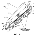
- FIG. 3 is a rear perspective view of the heat exchanger having the fan.
- an exhaust gas recirculation (EGR) cooling system is depicted generally at 10, and is disposed on an exhaust gas recirculation system, depicted generally at 12.
- the EGR cooling system 10 is configured for cooling the exhaust gases and using the recovered waste heat from the exhaust gases for useful purposes. It is contemplated that the EGR cooling system 10 can be used with trucks, buses and any other vehicles.
- the exhaust gas recirculation system 12 forms an exhaust gas passageway 14 for transferring gases emitted from an engine 16 to an ambient.
- the passageway 14 is formed with an exhaust inlet pipe 18, having an inlet 20 connected to an exhaust outlet 22 of the engine 16, and an exhaust outlet pipe 24, having an outlet 26 for venting the exhaust gases to the ambient.
- the EGR cooling system 10 cools exhaust gases from the exhaust gas recirculation system 12 before recirculating the exhaust gases into the intake manifold 29 of the engine 16, where they will flow to the combustion chamber (not shown).
- the exhaust gas recirculation system 12 is preferably mounted on a chassis member (not shown) using conventional mounting structures (not shown).
- the exhaust gas recirculation system 12 generally extends longitudinally along the length of the vehicle.
- the exhaust system 12 incorporates aftertreatment devices, and specifically, includes a pre-diesel oxidation catalyst member 32 and a diesel oxidation catalyst/diesel particulate filter (DOC/DPF) 34 downstream of the pre-oxidation catalyst on the exhaust gas passageway 14.
- a hydrocarbon doser 30 may also be disposed on the exhaust gas passageway upstream from the pre-diesel oxidation catalyst member 32.
- Exhaust gases are recirculated from an exhaust gas manifold 27 on the engine 16 on a recirculation line 28 to the intake manifold 29 of engine to intermix with air for combustion.
- the recirculation line 28 is in fluid communication with the exhaust gas manifold 27 and the intake manifold 29.
- an engine cooling system 38 circulates water or other coolant through a series of channels cast into the engine block and cylinder head (not shown), surrounding the combustion chambers (not shown), to carry the heat away from the engine 16 through the vehicle body.
- water or other coolant from the engine cooling system is circulated through an exhaust gas-to-coolant heat exchanger located at the engine 16 or on the exhaust gas passageway 14. This creates an additional loading on the engine cooling system 38.
- the EGR cooling system 10 is intended to replace the conventional exhaust gas-to-coolant heat exchanger, or alternatively, is intended to be used in addition to the conventional exhaust gas-to-coolant heat exchanger to help alleviate the loading on the engine cooling system 38.
- the present EGR cooler uses forced convection to cool the exhaust gas from the exhaust gas passageway 14.
- the EGR cooling system 10 uses ambient airflow to cool the exhaust gas from the exhaust gas passageway 14.
- the EGR cooling system 10 includes a forced convection, exhaust gas-to-air heat exchanger 36 in fluid communication with the engine 16.
- the heat exchanger 36 is disposed between and in fluid communication with the recirculation line 28 and the intake manifold 29 of the engine 16.
- the heat exchanger 36 is attached directly to the intake manifold 29 of the engine 16 and is in fluid communication with the recirculation line 28.
- the heat exchanger 36 is a forced convection cooler that includes a core assembly 40 having a plurality of tubes and fins running substantially the length of the heat exchanger. Bounding the periphery of the core assembly 40 are header members 42 running the length of the core assembly and parallel with the plurality of tubes and fins. Two end caps 44 are attached generally perpendicularly to the header members 42 to enclose the sides of the core assembly 40.
- An exhaust gas inlet 46 is located at a first end cap 42 of the forced convection heat exchanger 36, and an exhaust gas outlet 48 is located at the opposite end cap 42. Exhaust gases exiting the recirculation line 28 and entering the exhaust gas inlet 46 flow into the end cap 42 and pass through the tubes of the core assembly. It is contemplated that within the tubes, there are turbulators (not shown) that are configured to turbulate the flow of exhaust gas through the tube to more effectively transfer heat. When the exhaust gases flow the length of the tubes, the exhausts gases flow out of the opposite end cap 42 and pass out of the exhaust gas outlet 48. When the exhaust gases exit the exhaust gas outlet 48, they are cooled relative to the temperature of the incoming exhaust gases at the exhaust gas inlet 46.
- the forced convection heat exchanger 36 has a first side 50 having an airflow input surface 52 and a second side 54 with a duct 56 enclosing the second side.
- the air flows through the heat exchanger 36 in a direction indicated by the arrows in FIG. 2 , which is transverse to the plane of the heat exchanger 36.
- the air cools the tubes and fins as well as the exhaust gases contained in the tubes.
- At least one fan 58 is attached to the first side 50 to draw air into the airflow input surface 52.
- the fans 58 convectively force the heated air over the heat exchanger 36 to be collected by the duct 56 and channeled to the DOC/DPF 34.
- the energy required to operate the fan 58 would be in the range of 650 to 1000 Watts, however other amounts are contemplated.
- the duct 56 is disposed at the second side 54 of the heat exchanger 36 to collect the heated airflow emitted from the heat exchanger 36 and to direct it out of a duct outlet 60.
- the duct outlet 60 is located at a first end of the duct 56, which has a larger cross-sectional area than the second end of the duct.
- the cross-sectional area decreases a generally constant amount along the length of the duct 56 to the second end of the duct. In this configuration, the majority of the heat gets ducted to a waste heat line 62 and directed to the DOC/DPF 34.
- the heat exchanger 36 derives heat from the exhaust gases and uses this waste heat for other useful purposes.
- the waste heat line 62 provides the fluid communication between the airflow output 56 of the heat exchanger 36 to the DOC/DPF 34 and directs the flow of air to the DOC/DPF.
- the DOC/DPF 34 periodically goes through a regeneration cycle where deposits are burned off, which requires substantial heat energy.
- the waste heat from the heat exchanger 36 may provide additional heat to the DOC/DPF 34, which may reduce the build-up of deposits, and may reduce the number of regeneration cycles that are needed. Additionally, the waste heat from the forced convection heat exchanger 36 may provide heat (energy) to reduce the ramp up.
- the EGR cooler 10 including the forced convection heat exchanger 36 alleviates the loading on the engine cooling system.
- the heat exchanger 36 may provide the waste heat to the oxidation catalyst 32 for catalyst light off.
- the EGR cooler 10 having the forced convection heat exchanger 36 is mounted on the chassis 28, which may provide an efficient packaging of the engine. Further, the waste heat from the forced convection heat exchanger 36 may provide more energy for temperature ramp up. Further still, the forced convection heat exchanger 36 may allow less dosing of the aftertreatment and may potentially reduce the size of the DOC/DPF 34.
Landscapes
- Engineering & Computer Science (AREA)
- Chemical & Material Sciences (AREA)
- Mechanical Engineering (AREA)
- General Engineering & Computer Science (AREA)
- Combustion & Propulsion (AREA)
- Chemical Kinetics & Catalysis (AREA)
- Materials Engineering (AREA)
- Health & Medical Sciences (AREA)
- Toxicology (AREA)
- Thermal Sciences (AREA)
- Physics & Mathematics (AREA)
- Exhaust-Gas Circulating Devices (AREA)
- Exhaust Gas After Treatment (AREA)
- Processes For Solid Components From Exhaust (AREA)
Abstract
Description
- Embodiments described herein generally relate to exhaust gas conveyance systems in vehicles. More specifically, embodiments described herein relate to a forced convection heat exchanger for an exhaust gas recirculation (EGR) system of a vehicle for reducing the temperature of recirculated exhaust gases.
- Exhaust gas conveyance systems on vehicles may emit exhaust gases with extremely high temperatures, which can be achieved from routine engine operation. The engine cooling system is used to cool the exhaust gas before the exhaust gas is recirculated to the engine. The engine cooling system typically circulates water or other coolant from the engine cooling system and carries the heat away from the exhaust gases. Due to regulations imposed on vehicles to control exhaust gas emissions, there are increasing demands made on the engine cooling system to cool the exhaust gas, which reduces nitrous oxide NOx exhaust gas emissions.
- Exhaust gas coolers are located on an engine or on an exhaust gas passageway. The exhaust gas passageway routes the exhaust gases from the vehicle's engine to the ambient. A portion of the exhaust gases are recirculated from the engine exhaust manifold back to the intake manifold of the engine in an exhaust gas recirculation (EGR) system. Most EGR systems include at least one EGR cooler located between the exhaust manifold and the intake manifold of an engine.
- NOx is primarily formed when a mix of nitrogen and oxygen is subjected to high temperatures. Intermixing incoming air with recirculated exhaust gas dilutes the mix, which lowers the flame temperature and reduces the amount of excess oxygen. The exhaust gas also increases the specific heat capacity of the mix of air and exhaust gas, which lowers the peak combustion temperature. Since NOx is more readily formed at high temperatures, the EGR system limits the generation of NOx by keeping the temperatures low. In general, the cooler the recirculated exhaust gas, the less NOx that is produced at the engine.
- Engines using EGR to lower their NOx emissions can attain lower emissions by cooling the recirculated exhaust gas. The EGR coolers cool the exhaust gas so that the exhaust gas has a lower latent heat content. The cooled exhaust gas and air mixture lowers the combustion temperatures at the combustion chamber, which results in less NOx produced at the engine.
- In the direction of flow of the exhaust gases, the exhaust gas conveyance system often incorporates aftertreatment devices, such as a pre-diesel oxidation catalyst member (PDOC) and a diesel oxidation catalyst (DOC) or a diesel particulate filter (DPF). A DOC is a device that uses a chemical process to break down pollutants in the exhaust stream into less harmful components. The DOC has a porous ceramic honeycomb-like structure that is coated with a material that catalyzes a chemical reaction to reduce pollution. The DPF removes particulate matter from the exhaust gases.
- A method of cooling recirculated exhaust gas from an exhaust manifold of an engine upstream of an intake manifold, the method including passing the recirculated exhaust gas from the exhaust manifold through a heat exchanger, and convectively forcing ambient air to flow through the heat exchanger with at least one fan attached to the heat exchanger. The method also includes the step of passing the cooled recirculated exhaust gas to the intake manifold.
-
FIG. 1 is a schematic of an exhaust gas recirculation system having a forced convection heat exchanger. -
FIG. 2 is a front perspective view of the heat exchanger having a fan. -
FIG. 3 is a rear perspective view of the heat exchanger having the fan. - Referring now to
FIG. 1 , an exhaust gas recirculation (EGR) cooling system is depicted generally at 10, and is disposed on an exhaust gas recirculation system, depicted generally at 12. The EGRcooling system 10 is configured for cooling the exhaust gases and using the recovered waste heat from the exhaust gases for useful purposes. It is contemplated that the EGRcooling system 10 can be used with trucks, buses and any other vehicles. - The exhaust
gas recirculation system 12 forms anexhaust gas passageway 14 for transferring gases emitted from anengine 16 to an ambient. Thepassageway 14 is formed with anexhaust inlet pipe 18, having aninlet 20 connected to anexhaust outlet 22 of theengine 16, and anexhaust outlet pipe 24, having anoutlet 26 for venting the exhaust gases to the ambient. TheEGR cooling system 10 cools exhaust gases from the exhaustgas recirculation system 12 before recirculating the exhaust gases into theintake manifold 29 of theengine 16, where they will flow to the combustion chamber (not shown). - The exhaust
gas recirculation system 12 is preferably mounted on a chassis member (not shown) using conventional mounting structures (not shown). The exhaustgas recirculation system 12 generally extends longitudinally along the length of the vehicle. - In the direction of flow of the exhaust gases, the
exhaust system 12 incorporates aftertreatment devices, and specifically, includes a pre-dieseloxidation catalyst member 32 and a diesel oxidation catalyst/diesel particulate filter (DOC/DPF) 34 downstream of the pre-oxidation catalyst on theexhaust gas passageway 14. Ahydrocarbon doser 30 may also be disposed on the exhaust gas passageway upstream from the pre-dieseloxidation catalyst member 32. Exhaust gases are recirculated from anexhaust gas manifold 27 on theengine 16 on arecirculation line 28 to theintake manifold 29 of engine to intermix with air for combustion. Therecirculation line 28 is in fluid communication with theexhaust gas manifold 27 and theintake manifold 29. - As is conventionally known, an
engine cooling system 38 circulates water or other coolant through a series of channels cast into the engine block and cylinder head (not shown), surrounding the combustion chambers (not shown), to carry the heat away from theengine 16 through the vehicle body. In the conventional configuration, water or other coolant from the engine cooling system is circulated through an exhaust gas-to-coolant heat exchanger located at theengine 16 or on theexhaust gas passageway 14. This creates an additional loading on theengine cooling system 38. - The EGR
cooling system 10 is intended to replace the conventional exhaust gas-to-coolant heat exchanger, or alternatively, is intended to be used in addition to the conventional exhaust gas-to-coolant heat exchanger to help alleviate the loading on theengine cooling system 38. Instead of using water or coolant from the engine'scooling system 38 as a heat transfer fluid, the present EGR cooler uses forced convection to cool the exhaust gas from theexhaust gas passageway 14. Specifically, the EGRcooling system 10 uses ambient airflow to cool the exhaust gas from theexhaust gas passageway 14. - The EGR
cooling system 10 includes a forced convection, exhaust gas-to-air heat exchanger 36 in fluid communication with theengine 16. Theheat exchanger 36 is disposed between and in fluid communication with therecirculation line 28 and theintake manifold 29 of theengine 16. In one embodiment, theheat exchanger 36 is attached directly to theintake manifold 29 of theengine 16 and is in fluid communication with therecirculation line 28. - The
heat exchanger 36 is a forced convection cooler that includes acore assembly 40 having a plurality of tubes and fins running substantially the length of the heat exchanger. Bounding the periphery of thecore assembly 40 areheader members 42 running the length of the core assembly and parallel with the plurality of tubes and fins. Twoend caps 44 are attached generally perpendicularly to theheader members 42 to enclose the sides of thecore assembly 40. - An
exhaust gas inlet 46 is located at afirst end cap 42 of the forcedconvection heat exchanger 36, and anexhaust gas outlet 48 is located at theopposite end cap 42. Exhaust gases exiting therecirculation line 28 and entering theexhaust gas inlet 46 flow into theend cap 42 and pass through the tubes of the core assembly. It is contemplated that within the tubes, there are turbulators (not shown) that are configured to turbulate the flow of exhaust gas through the tube to more effectively transfer heat. When the exhaust gases flow the length of the tubes, the exhausts gases flow out of theopposite end cap 42 and pass out of theexhaust gas outlet 48. When the exhaust gases exit theexhaust gas outlet 48, they are cooled relative to the temperature of the incoming exhaust gases at theexhaust gas inlet 46. These cooled exhaust gases flow or pass from theheat exchanger 36 into theintake manifold 29, and from the intake manifold to the combustion chamber (not shown) of theengine 16. In one embodiment, approximately 50 kW of heat is rejected from the exhaust gases prior to reaching theintake manifold 29. - The forced
convection heat exchanger 36 has afirst side 50 having anairflow input surface 52 and asecond side 54 with aduct 56 enclosing the second side. The air flows through theheat exchanger 36 in a direction indicated by the arrows inFIG. 2 , which is transverse to the plane of theheat exchanger 36. As the air flows through theheat exchanger 36 transverse to the tubes and fins, the air cools the tubes and fins as well as the exhaust gases contained in the tubes. - At least one
fan 58 is attached to thefirst side 50 to draw air into theairflow input surface 52. In one embodiment of the forcedconvection heat exchanger 36, there are threefans 58 attached to theairflow input surface 52 to substantially enclose thesecond side 54 of the heat exchanger. To more effectively draw air, thefans 58 are in a relatively sealed fluid communication with theheat exchanger 36. - The
fans 58 convectively force the heated air over theheat exchanger 36 to be collected by theduct 56 and channeled to the DOC/DPF 34. In one embodiment, the energy required to operate thefan 58 would be in the range of 650 to 1000 Watts, however other amounts are contemplated. - The
duct 56 is disposed at thesecond side 54 of theheat exchanger 36 to collect the heated airflow emitted from theheat exchanger 36 and to direct it out of aduct outlet 60. Theduct outlet 60 is located at a first end of theduct 56, which has a larger cross-sectional area than the second end of the duct. The cross-sectional area decreases a generally constant amount along the length of theduct 56 to the second end of the duct. In this configuration, the majority of the heat gets ducted to awaste heat line 62 and directed to the DOC/DPF 34. - The
heat exchanger 36 derives heat from the exhaust gases and uses this waste heat for other useful purposes. Thewaste heat line 62 provides the fluid communication between theairflow output 56 of theheat exchanger 36 to the DOC/DPF 34 and directs the flow of air to the DOC/DPF. The DOC/DPF 34 periodically goes through a regeneration cycle where deposits are burned off, which requires substantial heat energy. The waste heat from theheat exchanger 36 may provide additional heat to the DOC/DPF 34, which may reduce the build-up of deposits, and may reduce the number of regeneration cycles that are needed. Additionally, the waste heat from the forcedconvection heat exchanger 36 may provide heat (energy) to reduce the ramp up. - The
EGR cooler 10 including the forcedconvection heat exchanger 36 alleviates the loading on the engine cooling system. In one embodiment, theheat exchanger 36 may provide the waste heat to theoxidation catalyst 32 for catalyst light off. Additionally, theEGR cooler 10 having the forcedconvection heat exchanger 36 is mounted on thechassis 28, which may provide an efficient packaging of the engine. Further, the waste heat from the forcedconvection heat exchanger 36 may provide more energy for temperature ramp up. Further still, the forcedconvection heat exchanger 36 may allow less dosing of the aftertreatment and may potentially reduce the size of the DOC/DPF 34.
Claims (20)
- An exhaust gas cooling system on a vehicle having an exhaust gas passageway that emits exhaust gases from an engine to an outlet, the cooling system comprising:a recirculation line in fluid communication with an exhaust manifold of the engine and an intake manifold of the engine;a heat exchanger disposed between and located in fluid communication with the recirculation line and the intake manifold, the heat exchanger having an exhaust gas inlet and an exhaust gas outlet for circulating exhaust gas through the heat exchanger, a first side and a second side for permitting the flow of air through the heat exchanger and cooling the exhaust gases, and at least one fan for drawing the air into the heat exchanger, wherein the cooled exhaust gases from the exhaust gas outlet flow to the intake manifold of the engine.
- The exhaust gas cooling system of claim 1 further comprising a diesel oxidation catalyst member located on the exhaust gas passageway, wherein the air flow through the heat exchanger is heated and flows out of the heat exchanger to the diesel oxidation catalyst member on a waste heat line.
- The exhaust gas cooling system of claim 1 further comprising a diesel particulate filter located on the exhaust gas passageway, wherein the air flow through the heat exchanger is heated and flows out of the second side and is directed to the diesel particulate filter on a waste heat line.
- The exhaust gas cooling system of claim 1 wherein the heat exchanger further comprises a core assembly having a plurality of tubes and fins running substantially the length of the heat exchanger.
- The exhaust gas cooling system of claim 4 further comprising header members that run the length of the core assembly and that are parallel with the plurality of tubes and fins.
- The exhaust gas cooling system of claim 5 further comprising two end caps that are attached generally perpendicularly to the header members on the sides of the core assembly.
- The exhaust gas cooling system of claim 1 further comprising a pre-diesel particulate filter located on the exhaust gas passageway downstream of the engine.
- The exhaust gas cooling system of claim 1 further comprising a dosing member located on the exhaust gas passageway downstream of the engine.
- The exhaust gas cooling system of claim 1 further comprising a duct at the second side of the heat exchanger, wherein the air flow is collected in the duct having a first end with a first cross-sectional area and a second end with a second cross-sectional area.
- The exhaust gas cooling system of claim 9 wherein the at least one fan comprises three fans that substantially enclose the second side.
- The exhaust gas cooling system of claim 1 wherein the fan is an electric fan.
- A heat exchanger for an exhaust gas recirculation system having an exhaust gas passageway that emits exhaust gases from an engine to an outlet, and an exhaust gas recirculation line in fluid communication with an exhaust gas manifold and an intake manifold of the engine, the heat exchanger comprising:an exhaust gas inlet for receiving exhaust gas from the exhaust gas recirculation line;an exhaust gas outlet for emitting exhaust gas to the intake manifold,a first side for receiving a flow of air;a second side for emitting a flow of air,at least one fan for drawing the flow of air into the first side, wherein the flow of air is heated by reducing the heat of the exhaust gas.
- The heat exchanger of claim 12 wherein the exhaust gas inlet is disposed on a first end cap and the exhaust gas outlet is disposed on a second end cap.
- The heat exchanger of claim 12 further comprising a duct attached to the second side for receiving the flow of air emitted at the second side, the duct having a duct outlet.
- The heat exchanger of claim 12 further comprising a waste heat line extending from the duct outlet.
- The heat exchanger of claim 15 wherein the at least one fan comprises three fans.
- The heat exchanger of claim 16 wherein the three fans substantially enclose the second side.
- A method of cooling recirculated exhaust gas from an exhaust manifold of an engine upstream of an intake manifold, the method comprising:passing the recirculated exhaust gas from the exhaust manifold through a heat exchanger,convectively forcing air to flow through the heat exchanger with at least one fan attached to the heat exchanger; andpassing the cooled recirculated exhaust gas to the intake manifold.
- The method of cooling recirculated exhaust gas of claim 18 including the step of collecting the heated air with a duct disposed on a side of the heat exchanger.
- The method of cooling recirculated exhaust gas of claim 19 including the step of directing the flow of heated air from the duct to a diesel oxidation catalyst on an exhaust gas passageway.
Applications Claiming Priority (1)
| Application Number | Priority Date | Filing Date | Title |
|---|---|---|---|
| US12/610,549 US20110100342A1 (en) | 2009-11-02 | 2009-11-02 | Forced convection egr cooling system |
Publications (2)
| Publication Number | Publication Date |
|---|---|
| EP2317110A2 true EP2317110A2 (en) | 2011-05-04 |
| EP2317110A3 EP2317110A3 (en) | 2011-09-28 |
Family
ID=43501437
Family Applications (1)
| Application Number | Title | Priority Date | Filing Date |
|---|---|---|---|
| EP10013819A Withdrawn EP2317110A3 (en) | 2009-11-02 | 2010-10-20 | Forced convection EGR cooling system |
Country Status (5)
| Country | Link |
|---|---|
| US (1) | US20110100342A1 (en) |
| EP (1) | EP2317110A3 (en) |
| JP (1) | JP2011094627A (en) |
| CN (1) | CN102052124B (en) |
| BR (1) | BRPI1004240A2 (en) |
Families Citing this family (3)
| Publication number | Priority date | Publication date | Assignee | Title |
|---|---|---|---|---|
| KR102805160B1 (en) * | 2019-12-12 | 2025-05-08 | 현대자동차주식회사 | Cooling water flow control device of cooling system for vehicle |
| US11725667B2 (en) | 2019-12-30 | 2023-08-15 | Cnh Industrial America Llc | Air source system of an agricultural system |
| US11566589B2 (en) | 2021-01-20 | 2023-01-31 | International Engine Intellectual Property Company, Llc | Exhaust gas recirculation cooler barrier layer |
Family Cites Families (40)
| Publication number | Priority date | Publication date | Assignee | Title |
|---|---|---|---|---|
| US5046554A (en) * | 1990-02-22 | 1991-09-10 | Calsonic International, Inc. | Cooling module |
| DE59100066D1 (en) * | 1991-07-17 | 1993-04-29 | Siemens Ag | HEATING AND / OR AIR CONDITIONING UNIT WITH AIR SIDE TEMPERATURE ADJUSTMENT FOR A MOTOR VEHICLE. |
| US5259206A (en) * | 1991-12-05 | 1993-11-09 | Danhard, Inc. | Compact condenser |
| US5476138A (en) * | 1993-08-16 | 1995-12-19 | Calsonic International, Inc. | Motor vehicle with improved radiator and condenser mounting device |
| US6216458B1 (en) * | 1997-03-31 | 2001-04-17 | Caterpillar Inc. | Exhaust gas recirculation system |
| JPH10331724A (en) * | 1997-05-29 | 1998-12-15 | Calsonic Corp | Egr gas cooling device |
| JPH1113556A (en) * | 1997-06-25 | 1999-01-19 | Calsonic Corp | Egr gas cooling device |
| DE19858293C1 (en) * | 1998-12-17 | 2000-03-09 | Daimler Chrysler Ag | Turbocharged internal combustion engine has common control for adjusting exhaust gas feedback valve and limit stop for variable geometry of exhaust gas turbine |
| US6324846B1 (en) * | 1999-03-31 | 2001-12-04 | Caterpillar Inc. | Exhaust gas recirculation system for an internal combustion engine |
| DE10061561A1 (en) * | 2000-12-07 | 2002-06-13 | Behr Gmbh & Co | Module carrier for various heat exchangers of a motor vehicle engine |
| US6843055B2 (en) * | 2001-06-22 | 2005-01-18 | Nissan Motor Co., Ltd. | Regeneration of diesel particulate filter for diesel engine |
| JP4062028B2 (en) * | 2002-09-19 | 2008-03-19 | 株式会社デンソー | Assembly structure of heat exchanger and shroud |
| JP4252340B2 (en) * | 2003-03-20 | 2009-04-08 | 東芝キヤリア株式会社 | refrigerator |
| JP4111070B2 (en) * | 2003-06-10 | 2008-07-02 | 株式会社デンソー | Heat exchanger for heating and air conditioner for vehicle |
| JP3928642B2 (en) * | 2005-01-18 | 2007-06-13 | いすゞ自動車株式会社 | EGR device |
| US7121254B2 (en) * | 2005-02-17 | 2006-10-17 | General Motors Corporation | Compression-ignited IC engine and method of operation |
| JP2006233936A (en) * | 2005-02-28 | 2006-09-07 | Mitsubishi Fuso Truck & Bus Corp | Exhaust gas purification device for internal combustion engine |
| ES2302323T3 (en) * | 2005-06-11 | 2008-07-01 | Modine Manufacturing Company | ENTIRE METALLIC HEAT EXCHANGERS AND PROCEDURE FOR MANUFACTURING. |
| DE102005042396A1 (en) * | 2005-09-06 | 2007-03-15 | Behr Gmbh & Co. Kg | Cooling system for a motor vehicle |
| US7210469B1 (en) * | 2005-10-24 | 2007-05-01 | International Engine Intellectual Property Company, Llc | Oxidation catalyst coating in a heat exchanger |
| US7210468B1 (en) * | 2005-10-24 | 2007-05-01 | International Engine Intellectual Property Company, Llc | Heat exchanger method and apparatus |
| JP2007182206A (en) * | 2005-12-06 | 2007-07-19 | Denso Corp | Heat exchanger and air conditioner for heating |
| JP2007224786A (en) * | 2006-02-22 | 2007-09-06 | Komatsu Ltd | Exhaust gas recirculation device |
| US7464700B2 (en) * | 2006-03-03 | 2008-12-16 | Proliance International Inc. | Method for cooling an internal combustion engine having exhaust gas recirculation and charge air cooling |
| US8573286B2 (en) * | 2006-03-10 | 2013-11-05 | Behr Gmbh & Co. Kg | Heat exchanger for a motor vehicle |
| US7448368B2 (en) * | 2006-11-17 | 2008-11-11 | Gm Global Technology Operations, Inc. | Exhaust gas recirculation system for an internal combustion engine |
| US7584748B2 (en) * | 2006-11-20 | 2009-09-08 | Gm Global Technology Operations, Inc. | Exhaust gas recirculation system for an internal combustion engine |
| US7934540B2 (en) * | 2007-02-01 | 2011-05-03 | Delphi Technologies, Inc. | Integrated liquid cooling unit for computers |
| US7788901B2 (en) * | 2007-02-19 | 2010-09-07 | Southwest Research Institute | Apparatus and method for regenerating exhaust treatment devices |
| JP2008261287A (en) * | 2007-04-12 | 2008-10-30 | Fuji Heavy Ind Ltd | Filter clogging judgment device for diesel engine |
| US20090100854A1 (en) * | 2007-10-18 | 2009-04-23 | Ilya Reyzin | Evaporatively cooled condenser |
| DE102007051659A1 (en) * | 2007-10-26 | 2009-04-30 | Behr Gmbh & Co. Kg | Device and method for the return of exhaust gas of an internal combustion engine |
| WO2009059923A2 (en) * | 2007-11-08 | 2009-05-14 | Avl List Gmbh | Internal combustion engine comprising an inlet system and an outlet system |
| WO2009094637A2 (en) * | 2008-01-24 | 2009-07-30 | Modine Manufacturing Company | Air-cooled heat exchanger and blower assembly and method |
| US7798134B2 (en) * | 2008-05-07 | 2010-09-21 | General Electric Company | System, kit, and method for locomotive exhaust gas recirculation cooling |
| US7757678B2 (en) * | 2008-05-07 | 2010-07-20 | General Electric Company | Locomotive exhaust gas recirculation cooling |
| JP4557063B2 (en) * | 2008-07-18 | 2010-10-06 | 株式会社デンソー | Particulate filter regeneration device and driving method thereof |
| WO2010037165A1 (en) * | 2008-09-30 | 2010-04-08 | Muller Industries Australia Pty Ltd | Cooling system with microchannel heat exchanger |
| US8031468B2 (en) * | 2009-06-03 | 2011-10-04 | American Power Conversion Corporation | Hot aisle containment cooling unit and method for cooling |
| JP5334928B2 (en) * | 2010-08-04 | 2013-11-06 | 三菱電機株式会社 | Air conditioner indoor unit and air conditioner |
-
2009
- 2009-11-02 US US12/610,549 patent/US20110100342A1/en not_active Abandoned
-
2010
- 2010-10-20 EP EP10013819A patent/EP2317110A3/en not_active Withdrawn
- 2010-10-29 BR BRPI1004240-7A patent/BRPI1004240A2/en not_active IP Right Cessation
- 2010-10-29 JP JP2010243344A patent/JP2011094627A/en active Pending
- 2010-11-01 CN CN2010105425033A patent/CN102052124B/en not_active Expired - Fee Related
Non-Patent Citations (1)
| Title |
|---|
| None |
Also Published As
| Publication number | Publication date |
|---|---|
| CN102052124B (en) | 2013-04-24 |
| JP2011094627A (en) | 2011-05-12 |
| BRPI1004240A2 (en) | 2012-06-12 |
| CN102052124A (en) | 2011-05-11 |
| US20110100342A1 (en) | 2011-05-05 |
| EP2317110A3 (en) | 2011-09-28 |
Similar Documents
| Publication | Publication Date | Title |
|---|---|---|
| US7131263B1 (en) | Exhaust gas recirculation cooler contaminant removal method and system | |
| US7966979B2 (en) | Mounting and cooling device for emissions system electronics | |
| US7210468B1 (en) | Heat exchanger method and apparatus | |
| KR100999607B1 (en) | Recirculating Exhaust Gas Cooling System and Cooling Method | |
| US20070089717A1 (en) | Oxidation catalyst coating in a heat exchanger | |
| US20100050631A1 (en) | System and method for locomotive exhaust gas recirculation cooling and catalyst heating | |
| US20120312013A1 (en) | System, method, and device for locomotive exhaust gas recirculation cooling and catalyst heating | |
| US7637099B2 (en) | Fluid entrainment apparatus | |
| EP2317110A2 (en) | Forced convection EGR cooling system | |
| CN102937057B (en) | A kind of engine exhaust-gas recirculating system | |
| KR100890337B1 (en) | Cooler of exhaust gas recirculation system of diesel engine | |
| KR100897269B1 (en) | Automobile exhaust gas recirculation device | |
| KR101060370B1 (en) | EBR equipment and engine system including the same | |
| KR101227178B1 (en) | Strucrure for removing the condensation water of Exhaust Gas Recirculation in diesel engine system and method thereof | |
| KR101221514B1 (en) | Egr cooler | |
| JP2010071215A (en) | Exhaust gas aftertreatment device of diesel engine | |
| CN220036807U (en) | Novel EGR module | |
| US9151250B2 (en) | Fluid cooling system | |
| KR101284416B1 (en) | Diesel exhaust gas recirculation(egr) apparatus | |
| KR20130056400A (en) | Exhaust gas recirculation cooler with heat expansion compensation structure | |
| KR100994378B1 (en) | EBR cooler for vehicle exhaust recirculation | |
| KR101282684B1 (en) | Exhaust gas recirculator cooler | |
| US20160230634A1 (en) | Active cooling assembly for sensor module | |
| KR20250085594A (en) | Apparatus for exhaust heat recovery and system including the same | |
| KR20020016034A (en) | Effeciency improving apparatus of heater and EGR cooler |
Legal Events
| Date | Code | Title | Description |
|---|---|---|---|
| PUAI | Public reference made under article 153(3) epc to a published international application that has entered the european phase |
Free format text: ORIGINAL CODE: 0009012 |
|
| AK | Designated contracting states |
Kind code of ref document: A2 Designated state(s): AL AT BE BG CH CY CZ DE DK EE ES FI FR GB GR HR HU IE IS IT LI LT LU LV MC MK MT NL NO PL PT RO RS SE SI SK SM TR |
|
| AX | Request for extension of the european patent |
Extension state: BA ME |
|
| PUAL | Search report despatched |
Free format text: ORIGINAL CODE: 0009013 |
|
| AK | Designated contracting states |
Kind code of ref document: A3 Designated state(s): AL AT BE BG CH CY CZ DE DK EE ES FI FR GB GR HR HU IE IS IT LI LT LU LV MC MK MT NL NO PL PT RO RS SE SI SK SM TR |
|
| AX | Request for extension of the european patent |
Extension state: BA ME |
|
| RIC1 | Information provided on ipc code assigned before grant |
Ipc: F01N 3/025 20060101ALI20110819BHEP Ipc: F01N 3/20 20060101ALI20110819BHEP Ipc: F02M 25/07 20060101AFI20110819BHEP |
|
| 17P | Request for examination filed |
Effective date: 20120328 |
|
| 17Q | First examination report despatched |
Effective date: 20120626 |
|
| GRAP | Despatch of communication of intention to grant a patent |
Free format text: ORIGINAL CODE: EPIDOSNIGR1 |
|
| INTG | Intention to grant announced |
Effective date: 20140919 |
|
| STAA | Information on the status of an ep patent application or granted ep patent |
Free format text: STATUS: THE APPLICATION IS DEEMED TO BE WITHDRAWN |
|
| 18D | Application deemed to be withdrawn |
Effective date: 20150130 |