EP2316980A1 - Non-oriented electromagnetic steel plate and method for manufacturing the same - Google Patents
Non-oriented electromagnetic steel plate and method for manufacturing the same Download PDFInfo
- Publication number
- EP2316980A1 EP2316980A1 EP09800350A EP09800350A EP2316980A1 EP 2316980 A1 EP2316980 A1 EP 2316980A1 EP 09800350 A EP09800350 A EP 09800350A EP 09800350 A EP09800350 A EP 09800350A EP 2316980 A1 EP2316980 A1 EP 2316980A1
- Authority
- EP
- European Patent Office
- Prior art keywords
- steel sheet
- electrical steel
- oriented electrical
- alloy film
- base material
- Prior art date
- Legal status (The legal status is an assumption and is not a legal conclusion. Google has not performed a legal analysis and makes no representation as to the accuracy of the status listed.)
- Granted
Links
Images



Classifications
-
- C—CHEMISTRY; METALLURGY
- C23—COATING METALLIC MATERIAL; COATING MATERIAL WITH METALLIC MATERIAL; CHEMICAL SURFACE TREATMENT; DIFFUSION TREATMENT OF METALLIC MATERIAL; COATING BY VACUUM EVAPORATION, BY SPUTTERING, BY ION IMPLANTATION OR BY CHEMICAL VAPOUR DEPOSITION, IN GENERAL; INHIBITING CORROSION OF METALLIC MATERIAL OR INCRUSTATION IN GENERAL
- C23C—COATING METALLIC MATERIAL; COATING MATERIAL WITH METALLIC MATERIAL; SURFACE TREATMENT OF METALLIC MATERIAL BY DIFFUSION INTO THE SURFACE, BY CHEMICAL CONVERSION OR SUBSTITUTION; COATING BY VACUUM EVAPORATION, BY SPUTTERING, BY ION IMPLANTATION OR BY CHEMICAL VAPOUR DEPOSITION, IN GENERAL
- C23C30/00—Coating with metallic material characterised only by the composition of the metallic material, i.e. not characterised by the coating process
-
- B—PERFORMING OPERATIONS; TRANSPORTING
- B32—LAYERED PRODUCTS
- B32B—LAYERED PRODUCTS, i.e. PRODUCTS BUILT-UP OF STRATA OF FLAT OR NON-FLAT, e.g. CELLULAR OR HONEYCOMB, FORM
- B32B15/00—Layered products comprising a layer of metal
- B32B15/01—Layered products comprising a layer of metal all layers being exclusively metallic
- B32B15/013—Layered products comprising a layer of metal all layers being exclusively metallic one layer being formed of an iron alloy or steel, another layer being formed of a metal other than iron or aluminium
- B32B15/015—Layered products comprising a layer of metal all layers being exclusively metallic one layer being formed of an iron alloy or steel, another layer being formed of a metal other than iron or aluminium the said other metal being copper or nickel or an alloy thereof
-
- C—CHEMISTRY; METALLURGY
- C21—METALLURGY OF IRON
- C21D—MODIFYING THE PHYSICAL STRUCTURE OF FERROUS METALS; GENERAL DEVICES FOR HEAT TREATMENT OF FERROUS OR NON-FERROUS METALS OR ALLOYS; MAKING METAL MALLEABLE, e.g. BY DECARBURISATION OR TEMPERING
- C21D8/00—Modifying the physical properties of ferrous metals or ferrous alloys by deformation combined with, or followed by, heat treatment
- C21D8/12—Modifying the physical properties of ferrous metals or ferrous alloys by deformation combined with, or followed by, heat treatment during manufacturing of articles with special electromagnetic properties
-
- C—CHEMISTRY; METALLURGY
- C22—METALLURGY; FERROUS OR NON-FERROUS ALLOYS; TREATMENT OF ALLOYS OR NON-FERROUS METALS
- C22C—ALLOYS
- C22C19/00—Alloys based on nickel or cobalt
- C22C19/03—Alloys based on nickel or cobalt based on nickel
-
- C—CHEMISTRY; METALLURGY
- C22—METALLURGY; FERROUS OR NON-FERROUS ALLOYS; TREATMENT OF ALLOYS OR NON-FERROUS METALS
- C22C—ALLOYS
- C22C38/00—Ferrous alloys, e.g. steel alloys
- C22C38/02—Ferrous alloys, e.g. steel alloys containing silicon
-
- C—CHEMISTRY; METALLURGY
- C22—METALLURGY; FERROUS OR NON-FERROUS ALLOYS; TREATMENT OF ALLOYS OR NON-FERROUS METALS
- C22C—ALLOYS
- C22C38/00—Ferrous alloys, e.g. steel alloys
- C22C38/06—Ferrous alloys, e.g. steel alloys containing aluminium
-
- C—CHEMISTRY; METALLURGY
- C22—METALLURGY; FERROUS OR NON-FERROUS ALLOYS; TREATMENT OF ALLOYS OR NON-FERROUS METALS
- C22C—ALLOYS
- C22C38/00—Ferrous alloys, e.g. steel alloys
- C22C38/18—Ferrous alloys, e.g. steel alloys containing chromium
- C22C38/40—Ferrous alloys, e.g. steel alloys containing chromium with nickel
-
- C—CHEMISTRY; METALLURGY
- C22—METALLURGY; FERROUS OR NON-FERROUS ALLOYS; TREATMENT OF ALLOYS OR NON-FERROUS METALS
- C22F—CHANGING THE PHYSICAL STRUCTURE OF NON-FERROUS METALS AND NON-FERROUS ALLOYS
- C22F1/00—Changing the physical structure of non-ferrous metals or alloys by heat treatment or by hot or cold working
- C22F1/10—Changing the physical structure of non-ferrous metals or alloys by heat treatment or by hot or cold working of nickel or cobalt or alloys based thereon
-
- C—CHEMISTRY; METALLURGY
- C23—COATING METALLIC MATERIAL; COATING MATERIAL WITH METALLIC MATERIAL; CHEMICAL SURFACE TREATMENT; DIFFUSION TREATMENT OF METALLIC MATERIAL; COATING BY VACUUM EVAPORATION, BY SPUTTERING, BY ION IMPLANTATION OR BY CHEMICAL VAPOUR DEPOSITION, IN GENERAL; INHIBITING CORROSION OF METALLIC MATERIAL OR INCRUSTATION IN GENERAL
- C23C—COATING METALLIC MATERIAL; COATING MATERIAL WITH METALLIC MATERIAL; SURFACE TREATMENT OF METALLIC MATERIAL BY DIFFUSION INTO THE SURFACE, BY CHEMICAL CONVERSION OR SUBSTITUTION; COATING BY VACUUM EVAPORATION, BY SPUTTERING, BY ION IMPLANTATION OR BY CHEMICAL VAPOUR DEPOSITION, IN GENERAL
- C23C28/00—Coating for obtaining at least two superposed coatings either by methods not provided for in a single one of groups C23C2/00 - C23C26/00 or by combinations of methods provided for in subclasses C23C and C25C or C25D
- C23C28/02—Coating for obtaining at least two superposed coatings either by methods not provided for in a single one of groups C23C2/00 - C23C26/00 or by combinations of methods provided for in subclasses C23C and C25C or C25D only coatings only including layers of metallic material
- C23C28/021—Coating for obtaining at least two superposed coatings either by methods not provided for in a single one of groups C23C2/00 - C23C26/00 or by combinations of methods provided for in subclasses C23C and C25C or C25D only coatings only including layers of metallic material including at least one metal alloy layer
-
- H—ELECTRICITY
- H01—ELECTRIC ELEMENTS
- H01F—MAGNETS; INDUCTANCES; TRANSFORMERS; SELECTION OF MATERIALS FOR THEIR MAGNETIC PROPERTIES
- H01F1/00—Magnets or magnetic bodies characterised by the magnetic materials therefor; Selection of materials for their magnetic properties
- H01F1/01—Magnets or magnetic bodies characterised by the magnetic materials therefor; Selection of materials for their magnetic properties of inorganic materials
- H01F1/03—Magnets or magnetic bodies characterised by the magnetic materials therefor; Selection of materials for their magnetic properties of inorganic materials characterised by their coercivity
- H01F1/12—Magnets or magnetic bodies characterised by the magnetic materials therefor; Selection of materials for their magnetic properties of inorganic materials characterised by their coercivity of soft-magnetic materials
- H01F1/14—Magnets or magnetic bodies characterised by the magnetic materials therefor; Selection of materials for their magnetic properties of inorganic materials characterised by their coercivity of soft-magnetic materials metals or alloys
- H01F1/16—Magnets or magnetic bodies characterised by the magnetic materials therefor; Selection of materials for their magnetic properties of inorganic materials characterised by their coercivity of soft-magnetic materials metals or alloys in the form of sheets
- H01F1/18—Magnets or magnetic bodies characterised by the magnetic materials therefor; Selection of materials for their magnetic properties of inorganic materials characterised by their coercivity of soft-magnetic materials metals or alloys in the form of sheets with insulating coating
-
- Y—GENERAL TAGGING OF NEW TECHNOLOGICAL DEVELOPMENTS; GENERAL TAGGING OF CROSS-SECTIONAL TECHNOLOGIES SPANNING OVER SEVERAL SECTIONS OF THE IPC; TECHNICAL SUBJECTS COVERED BY FORMER USPC CROSS-REFERENCE ART COLLECTIONS [XRACs] AND DIGESTS
- Y10—TECHNICAL SUBJECTS COVERED BY FORMER USPC
- Y10T—TECHNICAL SUBJECTS COVERED BY FORMER US CLASSIFICATION
- Y10T428/00—Stock material or miscellaneous articles
- Y10T428/12—All metal or with adjacent metals
- Y10T428/12493—Composite; i.e., plural, adjacent, spatially distinct metal components [e.g., layers, joint, etc.]
- Y10T428/12771—Transition metal-base component
- Y10T428/12861—Group VIII or IB metal-base component
- Y10T428/12931—Co-, Fe-, or Ni-base components, alternative to each other
Definitions
- the present invention relates to a non-oriented electrical steel sheet suitable for an iron core material of an electrical apparatus and a method of manufacturing the same.
- a low-loss electrical steel sheet has been used for a small-sized general-purpose motor and a compressor motor.
- the electrical steel sheet as above by mainly improving purity and coarsening crystal grains, a magnetizing property in a low magnetic field of about 1.0 T or less has been improved.
- the present invention has an object to provide a non-oriented electrical steel sheet in which a magnetic property in a low magnetic field is allowed to be further improved and a method of manufacturing the same.
- the present invention has been made in order to solve problems described above, and the gist thereof is as follows.
- magnetic domains on a surface of a base material are appropriately controlled, so that a magnetic property can be improved.
- the present inventors found that, when an Fe-Ni alloy film is coated on a base material of a non-oriented electrical steel sheet, magnetic domains in the vicinity of a surface of the non-oriented electrical steel sheet are aligned in a direction parallel to the surface thereof, though details will be described later. Further, as a result, the present inventors also found that a magnetizing property in a low magnetic field (that is, for example, 0.8 T or so) is improved. The improvement in the magnetizing property in the low magnetic field can contribute to achievement of energy saving of an electrical apparatus, for example. Note that in the following explanation, a unit of a content of an element is mass% or mass ppm.
- the present inventors formed an Fe-78%Ni alloy film on one surface of a non-oriented electrical steel sheet (base material) by a sputtering method. That is, one surface of a non-oriented electrical steel sheet was coated with an Fe-78 Ni alloy film. As the non-oriented electrical steel sheet, one containing C: 0.002%, Si: 3.0%, and Al: 0.5%, a balance of which being composed of Fe and inevitable impurities, and having a thickness of 0.35 mm was used. Further, a thickness of the Fe-78%Ni alloy film was set to 0.4 ⁇ m. Then, a DC magnetizing property was measured.
- the relative permeability ⁇ s in a low magnetic, field was increased as compared with the one having no Fe-78%Ni alloy film formed thereon. That is, a magnetic property in a low magnetic field was improved.
- the relative permeability ⁇ s was maximum.
- the relative permeability in the case of the maximum magnetic flux density Bm being 0.8T is a relative permeability to be obtained from a DC magnetization curve in which the maximum magnetic flux density is 0.8 T.
- the present inventors obtained a relationship between a frequency (20 Hz to 400 Hz) and a core loss W 1 in the case of the maximum magnetic flux density Bm being 1.5 T in the non-oriented electrical steel sheet having the Fe-78%Ni alloy film formed thereon. Further, in the non-oriented electrical steel sheet having no Fe-78 Ni alloy film formed thereon, they obtained a relationship between a frequency (20 Hz to 400 Hz) and a core loss W 2 in the case of the maximum magnetic flux density Bm being 1.5 T. Then, these relationships were compared.
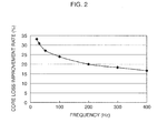
- Fig. 2 shows a relationship between a frequency and a core loss improvement rate.
- the core loss improvement rate was 15% or more.
- the formation of the Fe-78%Ni alloy film leads to the improvement of the relative permeability ⁇ s and the reduction of the core loss (a hysteresis loss).
- the core loss at the maximum magnetic flux density of 1.5 T and at a frequency of 50 Hz is described as W15/50.
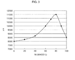
- the present inventors formed Fe-Ni alloy films having various compositions (Ni: 0% to 100%) on one surface of a non-oriented electrical steel sheet by an electroplating method in order to find the composition of the Fe-Ni alloy film suitable for improving a magnetic property. That is, one surface of a non-oriented electrical steel sheet was coated with Fe-Ni alloy films having different compositions. As the non-oriented electrical steel sheet, one containing C: 0.003%, Si: 2.1%, and Al: 0.3%, a balance of which being composed of Fe and inevitable impurities, and having a thickness of 0.35 mm was used. Further, thicknesses of the Fe-Ni alloy films were set to 0.3 ⁇ m in any of the compositions. Then, a DC magnetizing property was measured. When measuring the DC magnetizing property, the maximum magnetic flux density Bm was set to 0.8 T, and a relationship between a Ni content and the relative permeability ⁇ s was obtained. A result thereof is shown in Fig. 3 .
- the relative permeability ⁇ s was maximum.
- the composition of Fe-78.5%Ni is a permalloy composition having a high magnetic permeability.
- the relative permeability ⁇ s was low in the case when the Ni content exceeded 90%. It is possible to consider that such a tendency occurs because the composition in which the Ni content is less than 60% or the composition in which it exceeds 90% has a large difference in the permalloy composition.
- the present inventors formed Fe-Ni alloy films having various thicknesses (0.05 ⁇ m to 0.8 ⁇ m) on one surface of a non-oriented electrical steel sheet by an immersion plating method in order to find the thickness of the Fe-Ni alloy film suitable for improving a magnetic property. That is, one surface of a non-oriented electrical steel sheet was coated with Fe-Ni alloy films having different thicknesses. As the non-oriented electrical steel sheet, one containing C: 0.003%, Si: 2.4%, and Al: 0.5%, a balance of which being composed of Fe and inevitable impurities, and having a thickness of 0.35 mm was used. Further, the Ni contents of the Fe-Ni alloy films were set to 78% in any of the thicknesses. Then, a DC magnetizing property was measured.
- the maximum magnetic flux density Bm was set to 0.8 T, and a relationship between the thickness (a coating thickness) of the Fe-Ni alloy film and the relative permeability ⁇ s was obtained. Further, similar measurement was also conducted in one having the Fe-Ni alloy films formed on both surfaces of the non-oriented electrical steel sheet. Results thereof are shown in Fig. 4 .
- the reason why the relative permeability ⁇ s is extremely low when the thickness of the Fe-Ni alloy film is less than 0.1 ⁇ m is that magnetic domains on a surface of the non-oriented electrical steel sheet are not easily aligned despite forming the Fe-Ni alloy film. Further, the reason why the effect of improving the relative permeability ⁇ s is saturated is that as long as the magnetic domains on the surface of the non-oriented electrical steel sheet are sufficiently aligned, even though the Fe-Ni alloy film having the thickness of the above or more is formed, the magnetic domains are not easily aligned any more.
- the relative permeability ⁇ s in the case when the Fe-Ni alloy film was formed on one surface and the relative permeability ⁇ s in the case when the Fe-Ni alloy film was formed on both surfaces were equal to each other.
- the present inventors learned from these results of experiments that by forming the Fe-Ni alloy film on a surface of the non-oriented electrical steel sheet, the relative permeability and the core loss are dramatically improved. Further, the present inventors also learned that it is necessary that the Ni content of the Fe-Ni alloy film is 60% to 90% aid the thickness of the Fe-Ni alloy film is 0.1 ⁇ m or more for improving the relative permeability and the core loss.
- the present inventors also learned that when the thickness of the Fe-Ni alloy film exceeds 0.6 ⁇ m, the effect of improving the relative permeability and the core loss is saturated, and even though the Fe-Ni alloy film is formed on one surface or it is formed on both surfaces, the effect of improving the relative permeability and the core loss is equal to each other in both the cases.
- the C content is preferably 0.05% or less.
- Si is an element effective to increase electrical resistance, and when a Si content is less than 0.1%, it becomes difficult to obtain sufficient resistivity. On the other hand, when the Si content ratio of exceeds 7%, cold-rolling performance is easily lowered remarkably. Thus, the Si content is preferably not less than 0.1% nor more than 7%.
- Al is an element effective to increase electrical resistance similarly to Si. Further, Al is an element also contributing to deoxidation, and when an Al content is less than 0.01%, it is difficult to perform sufficient deoxidation. On the other hand, when the Al content exceeds 7%, castability is lowered, and productivity is easily lowered. Thus, the Al content is preferably not less than 0.01% nor more than 7%.
- non-oriented electrical steel sheet base material
- contents of Mn, Ti, N, S, Sn, Cu, and Ni preferably fall within the following ranges.
- Mn generates MnS, and has an effect of rendering S being an impurity harmless.
- Mn is preferably contained 0.1% or more. However, even though Mn is contained more than 1.0%, the effect of rendering S harmless becomes saturated.
- Ti generates nitride and/or carbide to deteriorate a magnetizing property and a core loss.
- the Ti content is preferably 30 ppm or less, and more preferably 15 ppm or less.
- N generates AlN and/or TiN to deteriorate a magnetizing property.
- the N content is preferably 0.0030% or less.
- the S content is preferably 30 ppm or less.
- Sn, Cu, and Ni have a function of inhibiting nitridation and oxidation of a surface of a non-oriented electrical steel sheet during annealing, which is strain relief annealing in particular, and have a function of improving an excitation property by an improvement in aggregate structure.
- Sn, Cu, and Ni are preferably contained 0.01% or more in total. These effects are equal among Sn, Cu, and Ni, so that at least one type of them is only sufficient to be contained. However, even though Sn, Cu, and Ni are contained more than 0.50% in total, the function of inhibiting nitridation and oxidation by atmosphere gas during annealing and the function of improving aggregate structure is saturated.
- the Fe-Ni alloy film is preferably composed of Fe: 10% to 40% and Ni: 90% to 60%, and more preferably composed of Fe: 15% to 30% and Ni: 85% to 70%. This is to obtain a good magnetic property in a low magnetic field.
- other metallic elements such as Mo may also be contained in the Fe-Ni alloy film.
- the Fe-Ni alloy film preferably contains Fe: 10% to 40% and Ni: 90 to 60%, and more preferably contains Fe: 15% to 30% and Ni: 85% to 70%.
- a method of forming the Fe-Ni alloy film on a surface of the non-oriented electrical steel sheet (base material) is not limited in particular. It is possible to form the Fe-Ni alloy film on a surface of the non-oriented electrical steel sheet by, for example, a dry coating method such as a PVD (physical vapor deposition) method and a CVD (chemical vapor deposition) method, and a wet coating method such as a plating method.
- a dry coating method such as a PVD (physical vapor deposition) method and a CVD (chemical vapor deposition) method
- a wet coating method such as a plating method.
- the thickness of the Fe-Ni alloy films is set to 0.1 ⁇ m or more. This is because the sufficient effects cannot be obtained when the thickness is less than 0.1 ⁇ m as described above. On the other hand, when the thickness of the Fe-Ni alloy film exceeds 0.6 ⁇ m, the effect of improving the relative permeability and the core loss is saturated, so that the thickness of the Fe-Ni alloy film is sufficiently 0.6 ⁇ m or less. However, the thickness may also exceed 0.6 ⁇ m for a reason such as operation stability.
- the Fe-Ni alloy film is sufficiently formed on one surface of the non-oriented electrical steel sheet (base material), but it may also be formed on both surfaces of the non-oriented electrical steel sheet (base material).
- the relative permeability ⁇ s in the rolling direction exhibited a maximum value at the maximum magnetic flux density Bm of 0.8 T or so, and the value was 10000 or more.
- the relative permeability ⁇ s of 10000 or more can be obtained at the maximum magnetic flux density Bm of 0.8 T.
- the core loss was improved by 15% or more.
- the core loss is improved by 10% or more.
- a method of manufacturing the non-oriented electrical steel sheet as the base material namely the non-oriented electrical steel sheet before the Fe-Ni alloy film is formed thereon, is not limited in particular, and the non-oriented electrical steel sheet can be manufactured according to a conventional method.
- annealing after hot rolling may also be performed as needed.
- a thickness of the non-oriented electrical steel sheet after cold rolling may also be set to 0.10 mm to 0.80 mm depending on a required property.
- a finish annealing temperature may also be adjusted within a range of 700°C to 1100°C depending on a required property.
- strain relief annealing may also be performed after a punching-out process of a motor core or the like.
- an insulating film is formed on a surface of the non-oriented electrical steel sheet after finish annealing, and the Fe-Ni alloy film may also be formed after the above insulating film is formed. Further, the Fe-Ni alloy film may also be formed before the above insulating film is formed.
- the non-oriented electrical steel sheet according to an embodiment of the present invention is provided with a structure shown in Fig. 5 , for example. That is, on one surface or both surfaces of a base material 1, an Fe-Ni alloy film 2 is formed. As shown in Fig. 6 , an insulating film 3 may also be formed between the base material 1 and the Fe-Ni alloy film 2, and as shown in Fig. 7 , the insulating film 3 may also be formed on the Fe-Ni alloy film 2.
- Each of Fe-Ni alloy films having compositions shown in Table 1 was formed on one surface or both surfaces of a non-oriented electrical steel sheet (base materials), which was after finish annealing and before an insulating film was formed thereof, by an electroplating method. That is, one surface or both surfaces of a non-oriented electrical steel sheet was/were coated with Fe-Ni alloy film(s).
- the non-oriented electrical steel sheet one containing C: 0.002%, Si: 3.2%, and Al: 1.0%, a balance of which being composed of Fe and inevitable impurities, and having a thickness of 0.35 mm was used. Further, thickness of the Fe-Ni alloy film was set to 0.5 ⁇ m per one surface.
- an insulating film was formed on an entire surface of the non-oriented electrical steel sheet. Then, the relative permeability ⁇ s in the rolling direction at the maximum magnetic flux density Bm of 0.8 T was measured. A result thereof is shown in Table 1.
- Each of Fe-78%Ni alloy films having thicknesses shown in Table 2 was formed on one surface of a non-oriented electrical steel sheet (base materials), which was after finish annealing and before an insulating film was formed thereon, by a PVD method. That is, Fe-78%Ni alloy film was coated on one surface of a non-oriented electrical steel sheet.
- the non-oriented electrical steel sheet one containing C: 0.001%, Si: 4.5%, and Al: 3.5%, a balance of which being composed of Fe and inevitable impurities, and having a thickness of 0.30 mm was used.
- an insulating film was formed on an entire surface of the non-oriented electrical steel sheet. Then, the relative permeability ⁇ s in the rolling direction at the maximum magnetic flux density Bm of 0.8 T was measured. A result thereof is shown in Table 2.
- Each of Fe-Ni alloy films having compositions shown in Table 3 was formed on one surface of a non-oriented electrical steel sheet (base material), which was after finish annealing and before an insulating film was formed thereon, by an immersion plating method. That is, an Fe-Ni alloy films was coated on one surface of a non-oriented electrical steel sheet.
- the non-oriented electrical steel sheet one containing C: 0.01%, Si: 2.5%, and Al : 4.5%, a balance of which being composed of Fe and inevitable impurities, and having a thickness of 0.50 mm was used. Further, thickness of the Fe-Ni alloy film was set to 0.4 ⁇ m.
- an insulating film was formed on an entire surface of the non-oriented electrical steel sheet.
- the relative permeability ⁇ s was 10000 or more in all samples in which the Fe-Ni alloy film was formed. Further, in the samples in which the Ni content of the Fe-Ni alloy film was 70% to 85%, the core loss improvement rate was increased to 10% or more.
- the present invention can be utilized for a non-oriented electrical steel sheet to be used for a motor or the like.
Landscapes
- Chemical & Material Sciences (AREA)
- Engineering & Computer Science (AREA)
- Materials Engineering (AREA)
- Mechanical Engineering (AREA)
- Metallurgy (AREA)
- Organic Chemistry (AREA)
- Physics & Mathematics (AREA)
- Crystallography & Structural Chemistry (AREA)
- Thermal Sciences (AREA)
- Chemical Kinetics & Catalysis (AREA)
- Dispersion Chemistry (AREA)
- Power Engineering (AREA)
- Electromagnetism (AREA)
- Manufacturing & Machinery (AREA)
- Soft Magnetic Materials (AREA)
- Manufacturing Of Steel Electrode Plates (AREA)
- Other Surface Treatments For Metallic Materials (AREA)
Abstract
Description
- The present invention relates to a non-oriented electrical steel sheet suitable for an iron core material of an electrical apparatus and a method of manufacturing the same.
- In recent years, a low-loss electrical steel sheet has been used for a small-sized general-purpose motor and a compressor motor. In the electrical steel sheet as above, by mainly improving purity and coarsening crystal grains, a magnetizing property in a low magnetic field of about 1.0 T or less has been improved.
- Further, in recent years, higher performance properties have been required for a non-oriented electrical steel sheet to be used as an iron core material of a rotor due to a worldwide increase in achievement of energy saving of an electrical apparatus.
- However, it is difficult to further improve purity of an electrical steel sheet industrially. Further, a reduction in a core loss by coarsening crystal grains is saturated when a crystal grain diameter is 150 µm or so, but a crystal grain diameter of a conventional electrical steel sheet has already reached 150 µm or so. Thus, even though crystal grains are further coarsened, it is difficult to further reduce a core loss.
- As described above, it has been difficult to further improve a magnetic property in a low magnetic field in a conventional art.
-
- Patent Document 1: Japanese Laid-open Patent Publication No.
07-070719 - Patent Document 2: Japanese Laid-open Patent Publication No.
08-165520 - Patent Document 3: Japanese Laid-open Patent Publication No.
08-283853 - The present invention has an object to provide a non-oriented electrical steel sheet in which a magnetic property in a low magnetic field is allowed to be further improved and a method of manufacturing the same.
- The present invention has been made in order to solve problems described above, and the gist thereof is as follows.
-
- (1) A non-oriented electrical steel sheet includes: a base material; and an Fe-Ni alloy film formed on at least one surface of the base material, containing, by mass%, Fe: 10% to 40% and Ni: 60% to 90%, and having a thickness of 0.1 µm or more.
- (2) The non-oriented electrical steel sheet described in (1), wherein the thickness of the Fe-Ni alloy film is equal to or less than 0.6 µm.
- (3) The non-oriented electrical steel sheet described in (1) or (2), in which the base material contains, by mass%: C: 0.05% or less; Si: not less than 0.1% nor more than 7.0%; and Al: not less than 0.01% nor more than 7.0%, and a balance of the base material is composed of Fe and inevitable impurities.
- (4) The non-oriented electrical steel sheet described in any one of (1) to (3), further includes an insulating film formed on a surface of the base material.
-
- (5) A method of manufacturing a non-oriented electrical steel sheet includes: forming, on at least one surface of a base material, an Fe-Ni alloy film that contains, by mass%, Fe: 10% to 40% and Ni: 60% to 90% to have a thickness of 0.1 µm or more.
- (6) The method of manufacturing the non-oriented electrical steel sheet described in (5), in which the thickness of the Fe-Ni alloy film is equal to or less than 0.6 µm.
- (7) The method of manufacturing the non-oriented electrical steel sheet described in (5) or (6), in which the base material contains, by mass%: C: 0.05% or less; Si: not less than 0.1% nor more than 7.0%; and Al: not less than 0.01% nor more than 7.0%, and a balance of the base material is composed of Fe and inevitable impurities.
- (8) The method of manufacturing the non-oriented electrical steel sheet described in any one of (5) to (7), further includes forming an insulating film on a surface of the base material, before the forming the Fe-Ni alloy film.
- (9) The method of manufacturing the non-oriented electrical steel sheet described tin any one of (5) to (7), further includes forming an insulating film on a surface of the base material, after the forming the Fe-Ni alloy film.
- According to the present invention, by a function of an appropriate Fe-Ni alloy film, magnetic domains on a surface of a base material are appropriately controlled, so that a magnetic property can be improved.
-
- [
Fig. 1] Fig. 1 is a view showing magnetic properties in case of a low magnetic field; - [
Fig. 2] Fig. 2 is a view showing a relationship between a frequency and a core loss improvement rate; - [
Fig. 3] Fig. 3 is a view showing a relationship between a Ni content and a relative permeability; - [
Fig. 4] Fig. 4 is a view showing relationships between a thickness of an Fe-Ni ally film and the relative permeability; - [
Fig. 5] Fig. 5 is a cross-sectional view showing a structure of a non-oriented electrical steel sheet according to an embodiment of the present invention; - [
Fig. 6] Fig. 6 is a cross-sectional view showing a structure of a non-oriented electrical steel sheet according to another embodiment of the present invention; and - [
Fig. 7] Fig. 7 is a cross-sectional view showing a structure of a non-oriented electrical steel sheet according to still another embodiment of the present invention. - The present inventors found that, when an Fe-Ni alloy film is coated on a base material of a non-oriented electrical steel sheet, magnetic domains in the vicinity of a surface of the non-oriented electrical steel sheet are aligned in a direction parallel to the surface thereof, though details will be described later. Further, as a result, the present inventors also found that a magnetizing property in a low magnetic field (that is, for example, 0.8 T or so) is improved. The improvement in the magnetizing property in the low magnetic field can contribute to achievement of energy saving of an electrical apparatus, for example. Note that in the following explanation, a unit of a content of an element is mass% or mass ppm.
- The present inventors formed an Fe-78%Ni alloy film on one surface of a non-oriented electrical steel sheet (base material) by a sputtering method. That is, one surface of a non-oriented electrical steel sheet was coated with an Fe-78 Ni alloy film. As the non-oriented electrical steel sheet, one containing C: 0.002%, Si: 3.0%, and Al: 0.5%, a balance of which being composed of Fe and inevitable impurities, and having a thickness of 0.35 mm was used. Further, a thickness of the Fe-78%Ni alloy film was set to 0.4 µm. Then, a DC magnetizing property was measured. When measuring the DC magnetizing property, a relationship between a maximum magnetic flux density Bm (0.4 T to 1.6 T) and a relative permeability µs was obtained. At this time, the relative permeability µs was measured in a rolling direction. For comparison, similar measurement was also conducted in a non-oriented electrical steel sheet having no Fe-78%Ni alloy film formed thereon. Results thereof are shown in
Fig. 1 . - As shown in
Fig. 1 , in the non-oriented electrical steel sheet having the Fe-78%Ni alloy film formed thereon, the relative permeability µs in a low magnetic, field was increased as compared with the one having no Fe-78%Ni alloy film formed thereon. That is, a magnetic property in a low magnetic field was improved. Particularly, in the case of the maximum magnetic flux density Bm being 0.8T or so, the relative permeability µs was maximum. Incidentally, the relative permeability in the case of the maximum magnetic flux density Bm being 0.8T is a relative permeability to be obtained from a DC magnetization curve in which the maximum magnetic flux density is 0.8 T. - The present inventors obtained a relationship between a frequency (20 Hz to 400 Hz) and a core loss W1 in the case of the maximum magnetic flux density Bm being 1.5 T in the non-oriented electrical steel sheet having the Fe-78%Ni alloy film formed thereon. Further, in the non-oriented electrical steel sheet having no Fe-78 Ni alloy film formed thereon, they obtained a relationship between a frequency (20 Hz to 400 Hz) and a core loss W2 in the case of the maximum magnetic flux density Bm being 1.5 T. Then, these relationships were compared.
- As a result, at frequencies of 400 Hz or less, the core loss W1 was lower than the core loss W2.
Fig. 2 shows a relationship between a frequency and a core loss improvement rate. The core loss improvement rate is expressed by the following expression.
core loss improvement rate (%) = 100 × (1 - W1/W2) - As shown in
Fig. 2 , at frequencies of 400 Hz or less, the core loss improvement rate was 15% or more. - When the results shown in
Fig. 1 and a result shown inFig. 2 are considered, it can be said that the formation of the Fe-78%Ni alloy film leads to the improvement of the relative permeability µs and the reduction of the core loss (a hysteresis loss). The core loss at the maximum magnetic flux density of 1.5 T and at a frequency of 50 Hz is described as W15/50. - The present inventors formed Fe-Ni alloy films having various compositions (Ni: 0% to 100%) on one surface of a non-oriented electrical steel sheet by an electroplating method in order to find the composition of the Fe-Ni alloy film suitable for improving a magnetic property. That is, one surface of a non-oriented electrical steel sheet was coated with Fe-Ni alloy films having different compositions. As the non-oriented electrical steel sheet, one containing C: 0.003%, Si: 2.1%, and Al: 0.3%, a balance of which being composed of Fe and inevitable impurities, and having a thickness of 0.35 mm was used. Further, thicknesses of the Fe-Ni alloy films were set to 0.3 µm in any of the compositions. Then, a DC magnetizing property was measured. When measuring the DC magnetizing property, the maximum magnetic flux density Bm was set to 0.8 T, and a relationship between a Ni content and the relative permeability µs was obtained. A result thereof is shown in
Fig. 3 . - As shown in
Fig. 3 , in the case of the Ni content being 78.5% or so, the relative permeability µs was maximum. Generally, the composition of Fe-78.5%Ni is a permalloy composition having a high magnetic permeability. On the other hand, in the case of the Ni content being less than 60%, in the case of it being less than 50% in particular, the relative permeability µs was low. Further, the relative permeability µs was low also in the case when the Ni content exceeded 90%. It is possible to consider that such a tendency occurs because the composition in which the Ni content is less than 60% or the composition in which it exceeds 90% has a large difference in the permalloy composition. - The present inventors formed Fe-Ni alloy films having various thicknesses (0.05 µm to 0.8µm) on one surface of a non-oriented electrical steel sheet by an immersion plating method in order to find the thickness of the Fe-Ni alloy film suitable for improving a magnetic property. That is, one surface of a non-oriented electrical steel sheet was coated with Fe-Ni alloy films having different thicknesses. As the non-oriented electrical steel sheet, one containing C: 0.003%, Si: 2.4%, and Al: 0.5%, a balance of which being composed of Fe and inevitable impurities, and having a thickness of 0.35 mm was used. Further, the Ni contents of the Fe-Ni alloy films were set to 78% in any of the thicknesses. Then, a DC magnetizing property was measured. When measuring the DC magnetizing property, the maximum magnetic flux density Bm was set to 0.8 T, and a relationship between the thickness (a coating thickness) of the Fe-Ni alloy film and the relative permeability µs was obtained. Further, similar measurement was also conducted in one having the Fe-Ni alloy films formed on both surfaces of the non-oriented electrical steel sheet. Results thereof are shown in
Fig. 4 . - As shown in
Fig. 4 , when the thickness of the Fe-Ni alloy film was less than 0.1 µm, the relative permeability µs was extremely low. Further, when the thickness of the Fe-Ni alloy film exceeded 0.6 µm, an effect of improving the relative permeability µs was saturated. - The reason why the relative permeability µs is extremely low when the thickness of the Fe-Ni alloy film is less than 0.1 µm is that magnetic domains on a surface of the non-oriented electrical steel sheet are not easily aligned despite forming the Fe-Ni alloy film. Further, the reason why the effect of improving the relative permeability µs is saturated is that as long as the magnetic domains on the surface of the non-oriented electrical steel sheet are sufficiently aligned, even though the Fe-Ni alloy film having the thickness of the above or more is formed, the magnetic domains are not easily aligned any more.
- Further, as shown in
Fig. 4 , the relative permeability µs in the case when the Fe-Ni alloy film was formed on one surface and the relative permeability µs in the case when the Fe-Ni alloy film was formed on both surfaces were equal to each other. - This is because when excitation, a magnetic flux concentrates in a region to be most easily magnetized in a thickness direction of the non-oriented electrical steel sheet. That is, the reason is that although the Fe-Ni alloy film is formed on a single region, (one surface) in the thickness direction, or the Fe-Ni alloy films are formed on two regions (both surfaces) in the thickness direction, it is in a single region that the magnetic flux concentrates most.
- The present inventors learned from these results of experiments that by forming the Fe-Ni alloy film on a surface of the non-oriented electrical steel sheet, the relative permeability and the core loss are dramatically improved. Further, the present inventors also learned that it is necessary that the Ni content of the Fe-Ni alloy film is 60% to 90% aid the thickness of the Fe-Ni alloy film is 0.1 µm or more for improving the relative permeability and the core loss. Further, the present inventors also learned that when the thickness of the Fe-Ni alloy film exceeds 0.6 µm, the effect of improving the relative permeability and the core loss is saturated, and even though the Fe-Ni alloy film is formed on one surface or it is formed on both surfaces, the effect of improving the relative permeability and the core loss is equal to each other in both the cases.
- Next, the details of the present invention that has been made based on these new findings will be explained. First, there will be explained a composition of a non-oriented electrical steel sheet itself (base material), on a surface of which an Fe-Ni alloy film is to be formed.
- When a C content exceeds 0.05%, a core loss is easily increased remarkably. Thus, the C content is preferably 0.05% or less.
- Si is an element effective to increase electrical resistance, and when a Si content is less than 0.1%, it becomes difficult to obtain sufficient resistivity. On the other hand, when the Si content ratio of exceeds 7%, cold-rolling performance is easily lowered remarkably. Thus, the Si content is preferably not less than 0.1% nor more than 7%.
- Al is an element effective to increase electrical resistance similarly to Si. Further, Al is an element also contributing to deoxidation, and when an Al content is less than 0.01%, it is difficult to perform sufficient deoxidation. On the other hand, when the Al content exceeds 7%, castability is lowered, and productivity is easily lowered. Thus, the Al content is preferably not less than 0.01% nor more than 7%.
- Further, other components of the non-oriented electrical steel sheet (base material) are not limited in particular, but contents of Mn, Ti, N, S, Sn, Cu, and Ni preferably fall within the following ranges.
- Mn generates MnS, and has an effect of rendering S being an impurity harmless. Thus, Mn is preferably contained 0.1% or more. However, even though Mn is contained more than 1.0%, the effect of rendering S harmless becomes saturated.
- Ti generates nitride and/or carbide to deteriorate a magnetizing property and a core loss. Thus, the Ti content is preferably 30 ppm or less, and more preferably 15 ppm or less.
- N generates AlN and/or TiN to deteriorate a magnetizing property. Thus, the N content is preferably 0.0030% or less.
- S generates MnS to deteriorate a magnetizing property and a core loss. Thus, the S content is preferably 30 ppm or less.
- Sn, Cu, and Ni have a function of inhibiting nitridation and oxidation of a surface of a non-oriented electrical steel sheet during annealing, which is strain relief annealing in particular, and have a function of improving an excitation property by an improvement in aggregate structure. Thus, Sn, Cu, and Ni are preferably contained 0.01% or more in total. These effects are equal among Sn, Cu, and Ni, so that at least one type of them is only sufficient to be contained. However, even though Sn, Cu, and Ni are contained more than 0.50% in total, the function of inhibiting nitridation and oxidation by atmosphere gas during annealing and the function of improving aggregate structure is saturated.
- Next, the Fe-Ni alloy film will be explained.
- The Fe-Ni alloy film is preferably composed of Fe: 10% to 40% and Ni: 90% to 60%, and more preferably composed of Fe: 15% to 30% and Ni: 85% to 70%. This is to obtain a good magnetic property in a low magnetic field. Incidentally, other metallic elements such as Mo may also be contained in the Fe-Ni alloy film. In the above case, the Fe-Ni alloy film preferably contains Fe: 10% to 40% and Ni: 90 to 60%, and more preferably contains Fe: 15% to 30% and Ni: 85% to 70%.
- A method of forming the Fe-Ni alloy film on a surface of the non-oriented electrical steel sheet (base material) is not limited in particular. It is possible to form the Fe-Ni alloy film on a surface of the non-oriented electrical steel sheet by, for example, a dry coating method such as a PVD (physical vapor deposition) method and a CVD (chemical vapor deposition) method, and a wet coating method such as a plating method.
- The thickness of the Fe-Ni alloy films is set to 0.1 µm or more. This is because the sufficient effects cannot be obtained when the thickness is less than 0.1 µm as described above. On the other hand, when the thickness of the Fe-Ni alloy film exceeds 0.6 µm, the effect of improving the relative permeability and the core loss is saturated, so that the thickness of the Fe-Ni alloy film is sufficiently 0.6 µm or less. However, the thickness may also exceed 0.6 µm for a reason such as operation stability.
- Further, as described above, the Fe-Ni alloy film is sufficiently formed on one surface of the non-oriented electrical steel sheet (base material), but it may also be formed on both surfaces of the non-oriented electrical steel sheet (base material).
- Next, there will be explained a magnetic property of the non-oriented electrical steel sheet having the Fe-Ni alloy film formed on at least one surface thereof.
- As for the DC magnetizing property of the non-oriented electrical steel sheet having the Fe-Ni alloy film formed on one surface thereof, in the above-described experiments, the relative permeability µs in the rolling direction exhibited a maximum value at the maximum magnetic flux density Bm of 0.8 T or so, and the value was 10000 or more. Thus, it is possible to consider that as long as minimum various conditions as above are satisfied, the relative permeability µs of 10000 or more can be obtained at the maximum magnetic flux density Bm of 0.8 T.
- Further, in the above-described experiments, at frequencies of 400 Hz or less, by forming the Fe-Ni alloy film, the core loss was improved by 15% or more. Thus, it is possible to consider that as long as the above-described minimum various conditions are satisfied, in any direction, by forming the Fe-Ni alloy film, the core loss is improved by 10% or more.
- Incidentally, a method of manufacturing the non-oriented electrical steel sheet as the base material, namely the non-oriented electrical steel sheet before the Fe-Ni alloy film is formed thereon, is not limited in particular, and the non-oriented electrical steel sheet can be manufactured according to a conventional method. For example, annealing after hot rolling may also be performed as needed. Further, a thickness of the non-oriented electrical steel sheet after cold rolling may also be set to 0.10 mm to 0.80 mm depending on a required property. Further, a finish annealing temperature may also be adjusted within a range of 700°C to 1100°C depending on a required property. Further, strain relief annealing may also be performed after a punching-out process of a motor core or the like.
- Further, when manufacturing the non-oriented electrical steel sheet as the base material, an insulating film is formed on a surface of the non-oriented electrical steel sheet after finish annealing, and the Fe-Ni alloy film may also be formed after the above insulating film is formed. Further, the Fe-Ni alloy film may also be formed before the above insulating film is formed.
- The non-oriented electrical steel sheet according to an embodiment of the present invention is provided with a structure shown in
Fig. 5 , for example. That is, on one surface or both surfaces of a base material 1, an Fe-Ni alloy film 2 is formed. As shown inFig. 6 , an insulatingfilm 3 may also be formed between the base material 1 and the Fe-Ni alloy film 2, and as shown inFig. 7 , the insulatingfilm 3 may also be formed on the Fe-Ni alloy film 2. - Next, there will be explained experiments for confirming the effects of the present invention conducted by the present inventors.
- Each of Fe-Ni alloy films having compositions shown in Table 1 was formed on one surface or both surfaces of a non-oriented electrical steel sheet (base materials), which was after finish annealing and before an insulating film was formed thereof, by an electroplating method. That is, one surface or both surfaces of a non-oriented electrical steel sheet was/were coated with Fe-Ni alloy film(s). As the non-oriented electrical steel sheet, one containing C: 0.002%, Si: 3.2%, and Al: 1.0%, a balance of which being composed of Fe and inevitable impurities, and having a thickness of 0.35 mm was used. Further, thickness of the Fe-Ni alloy film was set to 0.5 µm per one surface. Next, an insulating film was formed on an entire surface of the non-oriented electrical steel sheet. Then, the relative permeability µs in the rolling direction at the maximum magnetic flux density Bm of 0.8 T was measured. A result thereof is shown in Table 1.
-
[Table 1] Sample number Fe (mass%) Ni (mass%) Coated surface Relative permeability Note 1-1 48 52 one surface 8400 Comparative example both surfaces 8450 Comparative example 1-2 39 61 one surface 10100 invention example both surfaces 10200 Invention example 1-3 19 81 one surface 12000 Invention example both surfaces 11800 Invention example 1-4 11 89 one surface 10200 Invention example both surfaces 10100 Invention example 1-5 7 93 one surface 8800 Comparative example both surfaces 8900 Comparative example - As shown in Table 1, in samples in which the Ni content of the Fe-Ni allow film were 60% to 90%, the high relative permeability µs of 10000 or more was obtained. On the other hand, in a sample in which the Ni content was less than 60% and a sample in which the Ni content exceeded 90%, the relative permeability µs was lowered to less than 10000. These tendencies were common between the samples in which the Fe-Ni alloy film was formed on only one surface and the samples in which the Fe-Ni alloy films were formed on both surfaces.
- Each of Fe-78%Ni alloy films having thicknesses shown in Table 2 was formed on one surface of a non-oriented electrical steel sheet (base materials), which was after finish annealing and before an insulating film was formed thereon, by a PVD method. That is, Fe-78%Ni alloy film was coated on one surface of a non-oriented electrical steel sheet. As the non-oriented electrical steel sheet, one containing C: 0.001%, Si: 4.5%, and Al: 3.5%, a balance of which being composed of Fe and inevitable impurities, and having a thickness of 0.30 mm was used. Next, an insulating film was formed on an entire surface of the non-oriented electrical steel sheet. Then, the relative permeability µs in the rolling direction at the maximum magnetic flux density Bm of 0.8 T was measured. A result thereof is shown in Table 2.
-
[Table 2] Sample number Film thickness (µm) Relative permeability Evaluation 2-1 0.00 5000 × 2-2 0.05 8000 × 2-3 0.1 10000 ⊚ 2-4 0.2 10300 ⊚ 2-5 0.4 10500 ⊚ 2-6 0.6 10800 ⊚ 2-7 0.8 11000 O 2-8 0.9 11000 O 2-9 1.0 11000 O Evaluation: ⊚ particularly effective (the film thickness of 0.1 to 0.6 µm)
O one that is effective but saturated (the film thickness of over 0.6 µm)
× comparative example (the film thickness of less than 0.1. µm) - As shown in Table 2, in samples in which the thickness of the Fe-Ni alloy film was 0.1 µm or more, the high relative permeability µs of 10000 or more was obtained. Further, in samples in which the thickness of the Fe-Ni alloy film was less than 0.1 µm, the relative permeability µs was lowered to less than 10000. Further, when the thickness of the Fe-Ni alloy film exceeded 0.6 µm, the effects was saturated.
- Each of Fe-Ni alloy films having compositions shown in Table 3 was formed on one surface of a non-oriented electrical steel sheet (base material), which was after finish annealing and before an insulating film was formed thereon, by an immersion plating method. That is, an Fe-Ni alloy films was coated on one surface of a non-oriented electrical steel sheet. As the non-oriented electrical steel sheet, one containing C: 0.01%, Si: 2.5%, and Al : 4.5%, a balance of which being composed of Fe and inevitable impurities, and having a thickness of 0.50 mm was used. Further, thickness of the Fe-Ni alloy film was set to 0.4 µm. Next, an insulating film was formed on an entire surface of the non-oriented electrical steel sheet. Then, the relative permeability µs in the rolling direction at the maximum magnetic flux density Bm of 0.8 T was measured. Further, a core loss W15/50, (which is a core loss at the maximum magnetic flux density Bm of 1.5 T and at a frequency of 50 Hz), was also measured. Results thereof are shown in Table 3.
-
[Table 3] Sample number Fe (mass%) Ni (mass%) Relative permeability W15/50 (W/kg) Core loss improvement rate (%) Evaluation 3-1 - - 7000 2.35 base × 3-2 35 65 10100 2.22 5.5 O 3-3 30 70 11800 2.02 14.0 ⊚ 3-4 25 75 12300 1.98 15.7 ⊚ 3-5 20 80 12700 1.92 18.3 ⊚ 3-6 15 85 12100 2.05 12.8 ⊚ 3-7 10 90 10200 2.19 6.8 O Evaluation: ⊚ particularly effective (the core loss improvement rate of over 10%)
O effective (the relative permeability of 10000 or more, and the core loss improvement rate of less than 10%)
× comparative example (the relative permeability of less than 10000) - As shown in Table 3, the relative permeability µs was 10000 or more in all samples in which the Fe-Ni alloy film was formed. Further, in the samples in which the Ni content of the Fe-Ni alloy film was 70% to 85%, the core loss improvement rate was increased to 10% or more.
- The present invention can be utilized for a non-oriented electrical steel sheet to be used for a motor or the like.
Claims (16)
- A non-oriented electrical steel sheet comprising:a base material; andan Fe-Ni alloy film formed on at least one surface of said base material, containing, by mass%, Fe: 10% to 40% and Ni: 60% to 90%, and having a thickness of 0.1 µm or more.
- The non-oriented electrical steel sheet according to claim 1, wherein the thickness of said Fe-Ni alloy film is equal to or less than 0.6 µm.
- The non-oriented electrical steel sheet according to claim 1, wherein
said base material contains, by mass%:C: 0.05% or less;Si: not less than 0.1% nor more than 7.0%; andAl: not less than 0.01% nor more than 7.0%, anda balance of said base material is composed of Fe and inevitable impurities. - The non-oriented electrical steel sheet according to claim 2, wherein
said base material contains, by mass%:C: 0.05% or less;Si: not less than 0.1% nor more than 7.0%; andAl: not less than 0.01% nor more than 7.0%, anda balance of said base material is composed of Fe and inevitable impurities. - The non-oriented electrical steel sheet according to claim 1, further comprising an insulating film formed on a surface of said base material.
- The non-oriented electrical steel sheet according to claim 2, further comprising an insulating film formed on a surface of said base material.
- The non-oriented electrical steel sheet according to claim 3, further comprising an insulating film formed on a surface of said base material .
- The non-oriented electrical steel sheet according to claim 4, further comprising an insulating film formed on a surface of said base material.
- A method of manufacturing a non-oriented electrical steel sheet comprising:forming, on at least one surface of a base material, an Fe-Ni alloy film that contains, by mass%, Fe: 10% to 40% and Ni: 60% to 90% to have a thickness of 0.1 µm or more.
- The method of manufacturing a non-oriented electrical steel sheet according to claim 9, wherein the thickness of the Fe-Ni alloy film is equal to or less than 0.6 µm.
- The method of manufacturing a non-oriented electrical steel sheet according to claim 9, wherein
the base material contains, by mass%:C: 0.05% or less;Si: not less than 0.1% nor more than 7.0%; andAl: not less than 0.01% nor more than 7.0%, anda balance of the base material is composed of Fe and inevitable impurities. - The method of manufacturing a non-oriented electrical steel sheet according to claim 10, wherein
the base material contains, by mass%:C: 0.05% or less;Si: not less than 0.1% nor more than 7.0%; andAl: not less than 0.01% nor more than 7.0%, anda balance of the base material is composed of Fe and inevitable impurities. - The method of manufacturing a non-oriented electrical steel sheet according to claim 9, further comprising forming an insulating film on a surface of the base material, before said forming the Fe-Ni alloy film.
- The method of manufacturing a non-oriented electrical steel sheet according to claim 9, further comprising forming an insulating film on a surface of the base material, after said forming the Fe-Ni alloy film.
- The method of manufacturing a non-oriented electrical steel sheet according to claim 10, further comprising forming an insulating film on a surface of the base material, before said forming the Fe-Ni alloy film.
- The method of manufacturing a non-oriented electrical steel sheet according to claim 10, further comprising forming an insulating film on a surface of the base material, after said forming the Fe-Ni alloy film.
Priority Applications (1)
| Application Number | Priority Date | Filing Date | Title |
|---|---|---|---|
| PL09800350T PL2316980T3 (en) | 2008-07-22 | 2009-07-15 | Non-oriented electrical steel sheet and method for manufacturing the same |
Applications Claiming Priority (2)
| Application Number | Priority Date | Filing Date | Title |
|---|---|---|---|
| JP2008188997 | 2008-07-22 | ||
| PCT/JP2009/062822 WO2010010836A1 (en) | 2008-07-22 | 2009-07-15 | Non-oriented electromagnetic steel plate and method for manufacturing the same |
Publications (3)
| Publication Number | Publication Date |
|---|---|
| EP2316980A1 true EP2316980A1 (en) | 2011-05-04 |
| EP2316980A4 EP2316980A4 (en) | 2017-05-31 |
| EP2316980B1 EP2316980B1 (en) | 2018-11-14 |
Family
ID=41570301
Family Applications (1)
| Application Number | Title | Priority Date | Filing Date |
|---|---|---|---|
| EP09800350.2A Active EP2316980B1 (en) | 2008-07-22 | 2009-07-15 | Non-oriented electrical steel sheet and method for manufacturing the same |
Country Status (9)
| Country | Link |
|---|---|
| US (1) | US20110108307A1 (en) |
| EP (1) | EP2316980B1 (en) |
| JP (1) | JP4635112B2 (en) |
| KR (1) | KR101284466B1 (en) |
| CN (1) | CN102099501A (en) |
| PL (1) | PL2316980T3 (en) |
| RU (1) | RU2471013C2 (en) |
| TW (1) | TWI393792B (en) |
| WO (1) | WO2010010836A1 (en) |
Families Citing this family (8)
| Publication number | Priority date | Publication date | Assignee | Title |
|---|---|---|---|---|
| RU2454487C2 (en) * | 2008-01-24 | 2012-06-27 | Ниппон Стил Корпорейшн | Textured sheet from electrotechnical steel with high magnetic properties |
| US20130022833A1 (en) * | 2011-07-22 | 2013-01-24 | GM Global Technology Operations LLC | Electromagnetic machine and system including silicon steel sheets |
| CN103305748A (en) * | 2012-03-15 | 2013-09-18 | 宝山钢铁股份有限公司 | Non-oriented electrical steel plate and manufacturing method thereof |
| JP6296491B2 (en) * | 2013-03-14 | 2018-03-20 | セイコーインスツル株式会社 | Metal structure, method for manufacturing metal structure, spring component, start / stop lever for watch, and watch |
| MX376151B (en) * | 2014-07-02 | 2025-03-07 | Nippon Steel Corp | NON-ORIENTED GRAIN MAGNETIC STEEL SHEET AND MANUFACTURING METHOD THEREOF. |
| KR101649912B1 (en) * | 2014-12-18 | 2016-08-22 | 주식회사 포스코 | Non-orientied electrical steel sheet and method for manufacturing the same |
| DE102015218439A1 (en) * | 2015-09-25 | 2017-03-30 | Robert Bosch Gmbh | In its core losses reduced part and process for its preparation |
| KR102339193B1 (en) * | 2017-07-28 | 2021-12-13 | 제이에프이 스틸 가부시키가이샤 | Steel plate for battery cans, cans and batteries |
Family Cites Families (21)
| Publication number | Priority date | Publication date | Assignee | Title |
|---|---|---|---|---|
| JPS4725563B1 (en) * | 1969-06-21 | 1972-07-12 | ||
| JPS5314609A (en) * | 1976-07-27 | 1978-02-09 | Nippon Steel Corp | Production of nondirectional electromagnetic steel sheet free from ridging |
| CA1240949A (en) * | 1983-07-08 | 1988-08-23 | Kyoko Yamaji | Surface treated steel strip with coatings of iron-nickel alloy, tin and chromate |
| JPS62124228A (en) * | 1985-11-26 | 1987-06-05 | Kawasaki Steel Corp | Electrical steel sheet having superior suitability to blanking and superior corrosion resistance after strain relief annealing |
| JPS63219598A (en) * | 1987-03-09 | 1988-09-13 | Sumitomo Metal Ind Ltd | Electrical steel sheet having switching characteristic |
| JPH0434632A (en) * | 1990-05-31 | 1992-02-05 | Nec Corp | Memory system |
| JPH06116790A (en) * | 1992-10-01 | 1994-04-26 | Nippon Steel Corp | Welding can material with high-speed seam weldability, pitting corrosion resistance, heat resistance, and paint adhesion |
| JP3446257B2 (en) | 1993-09-07 | 2003-09-16 | Jfeスチール株式会社 | Non-oriented electrical steel sheet with excellent iron loss properties after strain relief annealing |
| JP2827861B2 (en) * | 1993-12-20 | 1998-11-25 | 住友金属工業株式会社 | Grain-oriented electrical steel sheet |
| RU2082770C1 (en) * | 1994-06-07 | 1997-06-27 | Акционерное общество "Новолипецкий металлургический комбинат" | Method for thermal rolling of cold-rolled strip of isotropic electrical steel |
| JPH08165520A (en) | 1994-12-09 | 1996-06-25 | Nippon Steel Corp | High silicon non-oriented electrical steel sheet excellent in workability and method of manufacturing the same |
| JPH08283853A (en) | 1995-04-11 | 1996-10-29 | Nippon Steel Corp | Manufacturing method of non-oriented electrical steel sheet with excellent magnetic properties |
| JPH0964583A (en) * | 1995-08-23 | 1997-03-07 | Mitsubishi Materials Corp | Electromagnetic shield material and shield cover |
| JP3544590B2 (en) * | 1995-09-19 | 2004-07-21 | 東洋鋼鈑株式会社 | Material for magnetic shielding for color picture tubes |
| RU2096516C1 (en) * | 1996-01-10 | 1997-11-20 | Акционерное общество "Новолипецкий металлургический комбинат" | Silicon electric steel and method of treatment thereof |
| JP3552501B2 (en) * | 1997-10-28 | 2004-08-11 | Jfeスチール株式会社 | Grain-oriented electrical steel sheet with extremely low iron loss and method for producing the same |
| JP3969456B2 (en) * | 1998-12-01 | 2007-09-05 | 住友電気工業株式会社 | Electromagnetic induction heating composite and electromagnetic induction heating cooking utensil |
| KR20010100204A (en) * | 2000-03-16 | 2001-11-14 | 이구택 | A coating composition for insulation film and a method for manufacturing insulation film of non-grain oriented electric steel sheet by using it |
| EP1632582B1 (en) * | 2003-05-06 | 2011-01-26 | Nippon Steel Corporation | Non-oriented electrical steel sheet excellent in core loss and manufacturing method thereof |
| JP4280181B2 (en) * | 2004-03-09 | 2009-06-17 | 新日本製鐵株式会社 | Steel plate for welding cans with excellent weldability, adhesion and corrosion resistance |
| RU2454487C2 (en) * | 2008-01-24 | 2012-06-27 | Ниппон Стил Корпорейшн | Textured sheet from electrotechnical steel with high magnetic properties |
-
2009
- 2009-07-15 EP EP09800350.2A patent/EP2316980B1/en active Active
- 2009-07-15 PL PL09800350T patent/PL2316980T3/en unknown
- 2009-07-15 CN CN200980128408.4A patent/CN102099501A/en active Pending
- 2009-07-15 US US13/001,240 patent/US20110108307A1/en not_active Abandoned
- 2009-07-15 WO PCT/JP2009/062822 patent/WO2010010836A1/en not_active Ceased
- 2009-07-15 RU RU2011106507/02A patent/RU2471013C2/en active
- 2009-07-15 KR KR1020117003888A patent/KR101284466B1/en active Active
- 2009-07-15 JP JP2010521683A patent/JP4635112B2/en active Active
- 2009-07-17 TW TW098124239A patent/TWI393792B/en active
Non-Patent Citations (1)
| Title |
|---|
| See references of WO2010010836A1 * |
Also Published As
| Publication number | Publication date |
|---|---|
| KR101284466B1 (en) | 2013-07-09 |
| CN102099501A (en) | 2011-06-15 |
| RU2011106507A (en) | 2012-08-27 |
| KR20110031990A (en) | 2011-03-29 |
| RU2471013C2 (en) | 2012-12-27 |
| PL2316980T3 (en) | 2019-03-29 |
| EP2316980B1 (en) | 2018-11-14 |
| EP2316980A4 (en) | 2017-05-31 |
| WO2010010836A1 (en) | 2010-01-28 |
| JP4635112B2 (en) | 2011-02-16 |
| TW201012949A (en) | 2010-04-01 |
| US20110108307A1 (en) | 2011-05-12 |
| TWI393792B (en) | 2013-04-21 |
| JPWO2010010836A1 (en) | 2012-01-05 |
Similar Documents
| Publication | Publication Date | Title |
|---|---|---|
| EP2316980B1 (en) | Non-oriented electrical steel sheet and method for manufacturing the same | |
| EP3875614B1 (en) | NON-ORIENTED ELECTRIC STEEL SHEET | |
| EP3399061B1 (en) | Non-oriented electrical steel sheet and method for manufacturing non-oriented electrical steel sheet | |
| EP3572545B1 (en) | Non-oriented electromagnetic steel sheet and production method therefor | |
| EP2540853B1 (en) | Non-oriented electrical steel sheet | |
| EP4079889A2 (en) | Non-oriented electrical steel sheet and method for manufacturing same | |
| JP4616935B2 (en) | Non-oriented electrical steel sheet and manufacturing method thereof | |
| US12421568B2 (en) | Non-oriented electrical steel sheet and method of manufacturing the same | |
| CN101821418A (en) | Non-oriented electromagnetic steel sheet with low high-frequency iron loss and method for producing same | |
| EP3556891B1 (en) | Non-oriented electrical steel sheet and manufacturing method therefor | |
| WO2020091043A1 (en) | Non-oriented electromagnetic steel sheet | |
| JPWO2020085448A1 (en) | Non-oriented electrical steel sheet and manufacturing method of laminated core using it | |
| EP4296381A1 (en) | Non-oriented electromagnetic steel sheet and manufacturing method therefor | |
| EP4137599A1 (en) | Non-oriented electromagnetic steel sheet and method for manufacturing same | |
| EP2474636B9 (en) | Non-oriented electrical steel sheet | |
| EP4386100A1 (en) | Non-oriented electrical steel sheet and method for manufacturing same | |
| JP4855225B2 (en) | Non-oriented electrical steel sheet with small anisotropy | |
| EP3859036A1 (en) | Non-oriented electrical steel sheet and manufacturing method therefor | |
| JP4258163B2 (en) | Non-oriented electrical steel sheet with excellent magnetic properties after strain relief annealing | |
| WO2021199400A1 (en) | Non-oriented electromagnetic steel sheet and method for producing same | |
| EP4632103A1 (en) | Hot-rolled non-oriented electrical steel sheet and method for manufacturing same | |
| JP2004076056A (en) | Non-oriented silicon steel sheet for semi-process |
Legal Events
| Date | Code | Title | Description |
|---|---|---|---|
| PUAI | Public reference made under article 153(3) epc to a published international application that has entered the european phase |
Free format text: ORIGINAL CODE: 0009012 |
|
| 17P | Request for examination filed |
Effective date: 20110216 |
|
| AK | Designated contracting states |
Kind code of ref document: A1 Designated state(s): AT BE BG CH CY CZ DE DK EE ES FI FR GB GR HR HU IE IS IT LI LT LU LV MC MK MT NL NO PL PT RO SE SI SK SM TR |
|
| AX | Request for extension of the european patent |
Extension state: AL BA RS |
|
| DAX | Request for extension of the european patent (deleted) | ||
| RIN1 | Information on inventor provided before grant (corrected) |
Inventor name: KOIKE, ISAO Inventor name: YAMAGUCHI, TOSHINAO Inventor name: USHIGAMI, YOSHIYUKI Inventor name: FUJII, HIROYASU Inventor name: ARITA, YOSHIHIRO Inventor name: HIRANO, SHIGERU |
|
| RAP1 | Party data changed (applicant data changed or rights of an application transferred) |
Owner name: NIPPON STEEL & SUMITOMO METAL CORPORATION |
|
| RA4 | Supplementary search report drawn up and despatched (corrected) |
Effective date: 20170503 |
|
| RIC1 | Information provided on ipc code assigned before grant |
Ipc: H01F 1/18 20060101ALI20170425BHEP Ipc: C22C 38/40 20060101ALI20170425BHEP Ipc: C23C 30/00 20060101ALI20170425BHEP Ipc: C23C 28/02 20060101ALI20170425BHEP Ipc: C22F 1/10 20060101ALI20170425BHEP Ipc: C22C 38/02 20060101ALI20170425BHEP Ipc: C22C 38/06 20060101ALI20170425BHEP Ipc: C22C 19/03 20060101ALI20170425BHEP Ipc: H01F 1/16 20060101ALI20170425BHEP Ipc: B32B 15/01 20060101ALI20170425BHEP Ipc: C21D 8/12 20060101ALI20170425BHEP Ipc: C22C 38/00 20060101AFI20170425BHEP |
|
| GRAP | Despatch of communication of intention to grant a patent |
Free format text: ORIGINAL CODE: EPIDOSNIGR1 |
|
| STAA | Information on the status of an ep patent application or granted ep patent |
Free format text: STATUS: GRANT OF PATENT IS INTENDED |
|
| RIC1 | Information provided on ipc code assigned before grant |
Ipc: C22C 38/02 20060101ALI20180119BHEP Ipc: C22F 1/10 20060101ALI20180119BHEP Ipc: C22C 38/40 20060101ALI20180119BHEP Ipc: C23C 30/00 20060101ALI20180119BHEP Ipc: B32B 15/01 20060101ALI20180119BHEP Ipc: C23C 28/02 20060101ALI20180119BHEP Ipc: C21D 8/12 20060101ALI20180119BHEP Ipc: C22C 38/00 20060101AFI20180119BHEP Ipc: H01F 1/18 20060101ALI20180119BHEP Ipc: H01F 1/16 20060101ALI20180119BHEP Ipc: C22C 19/03 20060101ALI20180119BHEP Ipc: C22C 38/06 20060101ALI20180119BHEP |
|
| INTG | Intention to grant announced |
Effective date: 20180213 |
|
| RIN1 | Information on inventor provided before grant (corrected) |
Inventor name: KOIKE, ISAO Inventor name: YAMAGUCHI, TOSHINAO Inventor name: FUJII, HIROYASU Inventor name: USHIGAMI, YOSHIYUKI Inventor name: HIRANO, SHIGERU Inventor name: ARITA, YOSHIHIRO |
|
| GRAS | Grant fee paid |
Free format text: ORIGINAL CODE: EPIDOSNIGR3 |
|
| GRAJ | Information related to disapproval of communication of intention to grant by the applicant or resumption of examination proceedings by the epo deleted |
Free format text: ORIGINAL CODE: EPIDOSDIGR1 |
|
| GRAL | Information related to payment of fee for publishing/printing deleted |
Free format text: ORIGINAL CODE: EPIDOSDIGR3 |
|
| STAA | Information on the status of an ep patent application or granted ep patent |
Free format text: STATUS: REQUEST FOR EXAMINATION WAS MADE |
|
| GRAP | Despatch of communication of intention to grant a patent |
Free format text: ORIGINAL CODE: EPIDOSNIGR1 |
|
| STAA | Information on the status of an ep patent application or granted ep patent |
Free format text: STATUS: GRANT OF PATENT IS INTENDED |
|
| INTC | Intention to grant announced (deleted) | ||
| RIN1 | Information on inventor provided before grant (corrected) |
Inventor name: YAMAGUCHI, TOSHINAO Inventor name: KOIKE, ISAO Inventor name: FUJII, HIROYASU Inventor name: USHIGAMI, YOSHIYUKI Inventor name: ARITA, YOSHIHIRO Inventor name: HIRANO, SHIGERU |
|
| INTG | Intention to grant announced |
Effective date: 20180724 |
|
| GRAA | (expected) grant |
Free format text: ORIGINAL CODE: 0009210 |
|
| STAA | Information on the status of an ep patent application or granted ep patent |
Free format text: STATUS: THE PATENT HAS BEEN GRANTED |
|
| AK | Designated contracting states |
Kind code of ref document: B1 Designated state(s): AT BE BG CH CY CZ DE DK EE ES FI FR GB GR HR HU IE IS IT LI LT LU LV MC MK MT NL NO PL PT RO SE SI SK SM TR |
|
| REG | Reference to a national code |
Ref country code: GB Ref legal event code: FG4D |
|
| REG | Reference to a national code |
Ref country code: CH Ref legal event code: EP Ref country code: AT Ref legal event code: REF Ref document number: 1064910 Country of ref document: AT Kind code of ref document: T Effective date: 20181115 |
|
| REG | Reference to a national code |
Ref country code: DE Ref legal event code: R096 Ref document number: 602009055680 Country of ref document: DE |
|
| REG | Reference to a national code |
Ref country code: IE Ref legal event code: FG4D |
|
| REG | Reference to a national code |
Ref country code: SE Ref legal event code: TRGR |
|
| REG | Reference to a national code |
Ref country code: NL Ref legal event code: MP Effective date: 20181114 |
|
| REG | Reference to a national code |
Ref country code: LT Ref legal event code: MG4D |
|
| PG25 | Lapsed in a contracting state [announced via postgrant information from national office to epo] |
Ref country code: IS Free format text: LAPSE BECAUSE OF FAILURE TO SUBMIT A TRANSLATION OF THE DESCRIPTION OR TO PAY THE FEE WITHIN THE PRESCRIBED TIME-LIMIT Effective date: 20190314 Ref country code: NO Free format text: LAPSE BECAUSE OF FAILURE TO SUBMIT A TRANSLATION OF THE DESCRIPTION OR TO PAY THE FEE WITHIN THE PRESCRIBED TIME-LIMIT Effective date: 20190214 Ref country code: LT Free format text: LAPSE BECAUSE OF FAILURE TO SUBMIT A TRANSLATION OF THE DESCRIPTION OR TO PAY THE FEE WITHIN THE PRESCRIBED TIME-LIMIT Effective date: 20181114 Ref country code: BG Free format text: LAPSE BECAUSE OF FAILURE TO SUBMIT A TRANSLATION OF THE DESCRIPTION OR TO PAY THE FEE WITHIN THE PRESCRIBED TIME-LIMIT Effective date: 20190214 Ref country code: ES Free format text: LAPSE BECAUSE OF FAILURE TO SUBMIT A TRANSLATION OF THE DESCRIPTION OR TO PAY THE FEE WITHIN THE PRESCRIBED TIME-LIMIT Effective date: 20181114 Ref country code: LV Free format text: LAPSE BECAUSE OF FAILURE TO SUBMIT A TRANSLATION OF THE DESCRIPTION OR TO PAY THE FEE WITHIN THE PRESCRIBED TIME-LIMIT Effective date: 20181114 Ref country code: HR Free format text: LAPSE BECAUSE OF FAILURE TO SUBMIT A TRANSLATION OF THE DESCRIPTION OR TO PAY THE FEE WITHIN THE PRESCRIBED TIME-LIMIT Effective date: 20181114 Ref country code: FI Free format text: LAPSE BECAUSE OF FAILURE TO SUBMIT A TRANSLATION OF THE DESCRIPTION OR TO PAY THE FEE WITHIN THE PRESCRIBED TIME-LIMIT Effective date: 20181114 |
|
| PG25 | Lapsed in a contracting state [announced via postgrant information from national office to epo] |
Ref country code: PT Free format text: LAPSE BECAUSE OF FAILURE TO SUBMIT A TRANSLATION OF THE DESCRIPTION OR TO PAY THE FEE WITHIN THE PRESCRIBED TIME-LIMIT Effective date: 20190314 Ref country code: GR Free format text: LAPSE BECAUSE OF FAILURE TO SUBMIT A TRANSLATION OF THE DESCRIPTION OR TO PAY THE FEE WITHIN THE PRESCRIBED TIME-LIMIT Effective date: 20190215 Ref country code: NL Free format text: LAPSE BECAUSE OF FAILURE TO SUBMIT A TRANSLATION OF THE DESCRIPTION OR TO PAY THE FEE WITHIN THE PRESCRIBED TIME-LIMIT Effective date: 20181114 |
|
| REG | Reference to a national code |
Ref country code: DE Ref legal event code: R082 Ref document number: 602009055680 Country of ref document: DE Representative=s name: VOSSIUS & PARTNER PATENTANWAELTE RECHTSANWAELT, DE Ref country code: DE Ref legal event code: R081 Ref document number: 602009055680 Country of ref document: DE Owner name: NIPPON STEEL CORPORATION, JP Free format text: FORMER OWNER: NIPPON STEEL & SUMITOMO METAL CORPORATION, TOKYO, JP |
|
| PG25 | Lapsed in a contracting state [announced via postgrant information from national office to epo] |
Ref country code: IT Free format text: LAPSE BECAUSE OF FAILURE TO SUBMIT A TRANSLATION OF THE DESCRIPTION OR TO PAY THE FEE WITHIN THE PRESCRIBED TIME-LIMIT Effective date: 20181114 Ref country code: DK Free format text: LAPSE BECAUSE OF FAILURE TO SUBMIT A TRANSLATION OF THE DESCRIPTION OR TO PAY THE FEE WITHIN THE PRESCRIBED TIME-LIMIT Effective date: 20181114 Ref country code: CZ Free format text: LAPSE BECAUSE OF FAILURE TO SUBMIT A TRANSLATION OF THE DESCRIPTION OR TO PAY THE FEE WITHIN THE PRESCRIBED TIME-LIMIT Effective date: 20181114 |
|
| REG | Reference to a national code |
Ref country code: DE Ref legal event code: R097 Ref document number: 602009055680 Country of ref document: DE |
|
| PG25 | Lapsed in a contracting state [announced via postgrant information from national office to epo] |
Ref country code: EE Free format text: LAPSE BECAUSE OF FAILURE TO SUBMIT A TRANSLATION OF THE DESCRIPTION OR TO PAY THE FEE WITHIN THE PRESCRIBED TIME-LIMIT Effective date: 20181114 Ref country code: SM Free format text: LAPSE BECAUSE OF FAILURE TO SUBMIT A TRANSLATION OF THE DESCRIPTION OR TO PAY THE FEE WITHIN THE PRESCRIBED TIME-LIMIT Effective date: 20181114 Ref country code: RO Free format text: LAPSE BECAUSE OF FAILURE TO SUBMIT A TRANSLATION OF THE DESCRIPTION OR TO PAY THE FEE WITHIN THE PRESCRIBED TIME-LIMIT Effective date: 20181114 Ref country code: SK Free format text: LAPSE BECAUSE OF FAILURE TO SUBMIT A TRANSLATION OF THE DESCRIPTION OR TO PAY THE FEE WITHIN THE PRESCRIBED TIME-LIMIT Effective date: 20181114 |
|
| PLBE | No opposition filed within time limit |
Free format text: ORIGINAL CODE: 0009261 |
|
| STAA | Information on the status of an ep patent application or granted ep patent |
Free format text: STATUS: NO OPPOSITION FILED WITHIN TIME LIMIT |
|
| 26N | No opposition filed |
Effective date: 20190815 |
|
| PG25 | Lapsed in a contracting state [announced via postgrant information from national office to epo] |
Ref country code: SI Free format text: LAPSE BECAUSE OF FAILURE TO SUBMIT A TRANSLATION OF THE DESCRIPTION OR TO PAY THE FEE WITHIN THE PRESCRIBED TIME-LIMIT Effective date: 20181114 |
|
| REG | Reference to a national code |
Ref country code: AT Ref legal event code: UEP Ref document number: 1064910 Country of ref document: AT Kind code of ref document: T Effective date: 20181114 |
|
| PG25 | Lapsed in a contracting state [announced via postgrant information from national office to epo] |
Ref country code: MC Free format text: LAPSE BECAUSE OF FAILURE TO SUBMIT A TRANSLATION OF THE DESCRIPTION OR TO PAY THE FEE WITHIN THE PRESCRIBED TIME-LIMIT Effective date: 20181114 |
|
| REG | Reference to a national code |
Ref country code: CH Ref legal event code: PL |
|
| GBPC | Gb: european patent ceased through non-payment of renewal fee |
Effective date: 20190715 |
|
| PG25 | Lapsed in a contracting state [announced via postgrant information from national office to epo] |
Ref country code: TR Free format text: LAPSE BECAUSE OF FAILURE TO SUBMIT A TRANSLATION OF THE DESCRIPTION OR TO PAY THE FEE WITHIN THE PRESCRIBED TIME-LIMIT Effective date: 20181114 |
|
| REG | Reference to a national code |
Ref country code: BE Ref legal event code: MM Effective date: 20190731 |
|
| PG25 | Lapsed in a contracting state [announced via postgrant information from national office to epo] |
Ref country code: GB Free format text: LAPSE BECAUSE OF NON-PAYMENT OF DUE FEES Effective date: 20190715 |
|
| PG25 | Lapsed in a contracting state [announced via postgrant information from national office to epo] |
Ref country code: BE Free format text: LAPSE BECAUSE OF NON-PAYMENT OF DUE FEES Effective date: 20190731 Ref country code: CH Free format text: LAPSE BECAUSE OF NON-PAYMENT OF DUE FEES Effective date: 20190731 Ref country code: LI Free format text: LAPSE BECAUSE OF NON-PAYMENT OF DUE FEES Effective date: 20190731 Ref country code: LU Free format text: LAPSE BECAUSE OF NON-PAYMENT OF DUE FEES Effective date: 20190715 |
|
| PG25 | Lapsed in a contracting state [announced via postgrant information from national office to epo] |
Ref country code: IE Free format text: LAPSE BECAUSE OF NON-PAYMENT OF DUE FEES Effective date: 20190715 |
|
| PG25 | Lapsed in a contracting state [announced via postgrant information from national office to epo] |
Ref country code: CY Free format text: LAPSE BECAUSE OF FAILURE TO SUBMIT A TRANSLATION OF THE DESCRIPTION OR TO PAY THE FEE WITHIN THE PRESCRIBED TIME-LIMIT Effective date: 20181114 |
|
| PG25 | Lapsed in a contracting state [announced via postgrant information from national office to epo] |
Ref country code: HU Free format text: LAPSE BECAUSE OF FAILURE TO SUBMIT A TRANSLATION OF THE DESCRIPTION OR TO PAY THE FEE WITHIN THE PRESCRIBED TIME-LIMIT; INVALID AB INITIO Effective date: 20090715 Ref country code: MT Free format text: LAPSE BECAUSE OF FAILURE TO SUBMIT A TRANSLATION OF THE DESCRIPTION OR TO PAY THE FEE WITHIN THE PRESCRIBED TIME-LIMIT Effective date: 20181114 |
|
| PG25 | Lapsed in a contracting state [announced via postgrant information from national office to epo] |
Ref country code: MK Free format text: LAPSE BECAUSE OF FAILURE TO SUBMIT A TRANSLATION OF THE DESCRIPTION OR TO PAY THE FEE WITHIN THE PRESCRIBED TIME-LIMIT Effective date: 20181114 |
|
| PGFP | Annual fee paid to national office [announced via postgrant information from national office to epo] |
Ref country code: PL Payment date: 20250528 Year of fee payment: 17 |
|
| PGFP | Annual fee paid to national office [announced via postgrant information from national office to epo] |
Ref country code: FR Payment date: 20250610 Year of fee payment: 17 |
|
| PGFP | Annual fee paid to national office [announced via postgrant information from national office to epo] |
Ref country code: SE Payment date: 20250528 Year of fee payment: 17 |
|
| PGFP | Annual fee paid to national office [announced via postgrant information from national office to epo] |
Ref country code: DE Payment date: 20250528 Year of fee payment: 17 |
|
| PGFP | Annual fee paid to national office [announced via postgrant information from national office to epo] |
Ref country code: AT Payment date: 20250625 Year of fee payment: 17 |